EP2307188B2 - Process for manufacturing a safety razor cartridge, and safety razor cartridge - Google Patents
Process for manufacturing a safety razor cartridge, and safety razor cartridge Download PDFInfo
- Publication number
- EP2307188B2 EP2307188B2 EP08786247.0A EP08786247A EP2307188B2 EP 2307188 B2 EP2307188 B2 EP 2307188B2 EP 08786247 A EP08786247 A EP 08786247A EP 2307188 B2 EP2307188 B2 EP 2307188B2
- Authority
- EP
- European Patent Office
- Prior art keywords
- platform
- cover
- plane
- portions
- cap portion
- Prior art date
- Legal status (The legal status is an assumption and is not a legal conclusion. Google has not performed a legal analysis and makes no representation as to the accuracy of the status listed.)
- Active
Links
Images


Classifications
-
- B—PERFORMING OPERATIONS; TRANSPORTING
- B26—HAND CUTTING TOOLS; CUTTING; SEVERING
- B26B—HAND-HELD CUTTING TOOLS NOT OTHERWISE PROVIDED FOR
- B26B21/00—Razors of the open or knife type; Safety razors or other shaving implements of the planing type; Hair-trimming devices involving a razor-blade; Equipment therefor
- B26B21/08—Razors of the open or knife type; Safety razors or other shaving implements of the planing type; Hair-trimming devices involving a razor-blade; Equipment therefor involving changeable blades
- B26B21/14—Safety razors with one or more blades arranged transversely to the handle
- B26B21/22—Safety razors with one or more blades arranged transversely to the handle involving several blades to be used simultaneously
- B26B21/222—Safety razors with one or more blades arranged transversely to the handle involving several blades to be used simultaneously with the blades moulded into, or attached to, a changeable unit
-
- B—PERFORMING OPERATIONS; TRANSPORTING
- B26—HAND CUTTING TOOLS; CUTTING; SEVERING
- B26B—HAND-HELD CUTTING TOOLS NOT OTHERWISE PROVIDED FOR
- B26B21/00—Razors of the open or knife type; Safety razors or other shaving implements of the planing type; Hair-trimming devices involving a razor-blade; Equipment therefor
- B26B21/40—Details or accessories
- B26B21/4012—Housing details, e.g. for cartridges
-
- B—PERFORMING OPERATIONS; TRANSPORTING
- B26—HAND CUTTING TOOLS; CUTTING; SEVERING
- B26B—HAND-HELD CUTTING TOOLS NOT OTHERWISE PROVIDED FOR
- B26B21/00—Razors of the open or knife type; Safety razors or other shaving implements of the planing type; Hair-trimming devices involving a razor-blade; Equipment therefor
- B26B21/40—Details or accessories
- B26B21/4068—Mounting devices; Manufacture of razors or cartridges
- B26B21/4075—Mounting devices
-
- B—PERFORMING OPERATIONS; TRANSPORTING
- B29—WORKING OF PLASTICS; WORKING OF SUBSTANCES IN A PLASTIC STATE IN GENERAL
- B29C—SHAPING OR JOINING OF PLASTICS; SHAPING OF MATERIAL IN A PLASTIC STATE, NOT OTHERWISE PROVIDED FOR; AFTER-TREATMENT OF THE SHAPED PRODUCTS, e.g. REPAIRING
- B29C65/00—Joining or sealing of preformed parts, e.g. welding of plastics materials; Apparatus therefor
- B29C65/02—Joining or sealing of preformed parts, e.g. welding of plastics materials; Apparatus therefor by heating, with or without pressure
- B29C65/08—Joining or sealing of preformed parts, e.g. welding of plastics materials; Apparatus therefor by heating, with or without pressure using ultrasonic vibrations
-
- B—PERFORMING OPERATIONS; TRANSPORTING
- B29—WORKING OF PLASTICS; WORKING OF SUBSTANCES IN A PLASTIC STATE IN GENERAL
- B29C—SHAPING OR JOINING OF PLASTICS; SHAPING OF MATERIAL IN A PLASTIC STATE, NOT OTHERWISE PROVIDED FOR; AFTER-TREATMENT OF THE SHAPED PRODUCTS, e.g. REPAIRING
- B29C65/00—Joining or sealing of preformed parts, e.g. welding of plastics materials; Apparatus therefor
- B29C65/78—Means for handling the parts to be joined, e.g. for making containers or hollow articles, e.g. means for handling sheets, plates, web-like materials, tubular articles, hollow articles or elements to be joined therewith; Means for discharging the joined articles from the joining apparatus
- B29C65/7841—Holding or clamping means for handling purposes
-
- B—PERFORMING OPERATIONS; TRANSPORTING
- B29—WORKING OF PLASTICS; WORKING OF SUBSTANCES IN A PLASTIC STATE IN GENERAL
- B29C—SHAPING OR JOINING OF PLASTICS; SHAPING OF MATERIAL IN A PLASTIC STATE, NOT OTHERWISE PROVIDED FOR; AFTER-TREATMENT OF THE SHAPED PRODUCTS, e.g. REPAIRING
- B29C66/00—General aspects of processes or apparatus for joining preformed parts
- B29C66/01—General aspects dealing with the joint area or with the area to be joined
- B29C66/05—Particular design of joint configurations
- B29C66/20—Particular design of joint configurations particular design of the joint lines, e.g. of the weld lines
- B29C66/21—Particular design of joint configurations particular design of the joint lines, e.g. of the weld lines said joint lines being formed by a single dot or dash or by several dots or dashes, i.e. spot joining or spot welding
-
- B—PERFORMING OPERATIONS; TRANSPORTING
- B29—WORKING OF PLASTICS; WORKING OF SUBSTANCES IN A PLASTIC STATE IN GENERAL
- B29C—SHAPING OR JOINING OF PLASTICS; SHAPING OF MATERIAL IN A PLASTIC STATE, NOT OTHERWISE PROVIDED FOR; AFTER-TREATMENT OF THE SHAPED PRODUCTS, e.g. REPAIRING
- B29C66/00—General aspects of processes or apparatus for joining preformed parts
- B29C66/01—General aspects dealing with the joint area or with the area to be joined
- B29C66/05—Particular design of joint configurations
- B29C66/302—Particular design of joint configurations the area to be joined comprising melt initiators
- B29C66/3022—Particular design of joint configurations the area to be joined comprising melt initiators said melt initiators being integral with at least one of the parts to be joined
- B29C66/30223—Particular design of joint configurations the area to be joined comprising melt initiators said melt initiators being integral with at least one of the parts to be joined said melt initiators being rib-like
-
- B—PERFORMING OPERATIONS; TRANSPORTING
- B29—WORKING OF PLASTICS; WORKING OF SUBSTANCES IN A PLASTIC STATE IN GENERAL
- B29C—SHAPING OR JOINING OF PLASTICS; SHAPING OF MATERIAL IN A PLASTIC STATE, NOT OTHERWISE PROVIDED FOR; AFTER-TREATMENT OF THE SHAPED PRODUCTS, e.g. REPAIRING
- B29C66/00—General aspects of processes or apparatus for joining preformed parts
- B29C66/50—General aspects of joining tubular articles; General aspects of joining long products, i.e. bars or profiled elements; General aspects of joining single elements to tubular articles, hollow articles or bars; General aspects of joining several hollow-preforms to form hollow or tubular articles
- B29C66/51—Joining tubular articles, profiled elements or bars; Joining single elements to tubular articles, hollow articles or bars; Joining several hollow-preforms to form hollow or tubular articles
- B29C66/54—Joining several hollow-preforms, e.g. half-shells, to form hollow articles, e.g. for making balls, containers; Joining several hollow-preforms, e.g. half-cylinders, to form tubular articles
-
- B—PERFORMING OPERATIONS; TRANSPORTING
- B29—WORKING OF PLASTICS; WORKING OF SUBSTANCES IN A PLASTIC STATE IN GENERAL
- B29C—SHAPING OR JOINING OF PLASTICS; SHAPING OF MATERIAL IN A PLASTIC STATE, NOT OTHERWISE PROVIDED FOR; AFTER-TREATMENT OF THE SHAPED PRODUCTS, e.g. REPAIRING
- B29C66/00—General aspects of processes or apparatus for joining preformed parts
- B29C66/70—General aspects of processes or apparatus for joining preformed parts characterised by the composition, physical properties or the structure of the material of the parts to be joined; Joining with non-plastics material
- B29C66/73—General aspects of processes or apparatus for joining preformed parts characterised by the composition, physical properties or the structure of the material of the parts to be joined; Joining with non-plastics material characterised by the intensive physical properties of the material of the parts to be joined, by the optical properties of the material of the parts to be joined, by the extensive physical properties of the parts to be joined, by the state of the material of the parts to be joined or by the material of the parts to be joined being a thermoplastic or a thermoset
- B29C66/739—General aspects of processes or apparatus for joining preformed parts characterised by the composition, physical properties or the structure of the material of the parts to be joined; Joining with non-plastics material characterised by the intensive physical properties of the material of the parts to be joined, by the optical properties of the material of the parts to be joined, by the extensive physical properties of the parts to be joined, by the state of the material of the parts to be joined or by the material of the parts to be joined being a thermoplastic or a thermoset characterised by the material of the parts to be joined being a thermoplastic or a thermoset
- B29C66/7392—General aspects of processes or apparatus for joining preformed parts characterised by the composition, physical properties or the structure of the material of the parts to be joined; Joining with non-plastics material characterised by the intensive physical properties of the material of the parts to be joined, by the optical properties of the material of the parts to be joined, by the extensive physical properties of the parts to be joined, by the state of the material of the parts to be joined or by the material of the parts to be joined being a thermoplastic or a thermoset characterised by the material of the parts to be joined being a thermoplastic or a thermoset characterised by the material of at least one of the parts being a thermoplastic
- B29C66/73921—General aspects of processes or apparatus for joining preformed parts characterised by the composition, physical properties or the structure of the material of the parts to be joined; Joining with non-plastics material characterised by the intensive physical properties of the material of the parts to be joined, by the optical properties of the material of the parts to be joined, by the extensive physical properties of the parts to be joined, by the state of the material of the parts to be joined or by the material of the parts to be joined being a thermoplastic or a thermoset characterised by the material of the parts to be joined being a thermoplastic or a thermoset characterised by the material of at least one of the parts being a thermoplastic characterised by the materials of both parts being thermoplastics
-
- B—PERFORMING OPERATIONS; TRANSPORTING
- B29—WORKING OF PLASTICS; WORKING OF SUBSTANCES IN A PLASTIC STATE IN GENERAL
- B29C—SHAPING OR JOINING OF PLASTICS; SHAPING OF MATERIAL IN A PLASTIC STATE, NOT OTHERWISE PROVIDED FOR; AFTER-TREATMENT OF THE SHAPED PRODUCTS, e.g. REPAIRING
- B29C66/00—General aspects of processes or apparatus for joining preformed parts
- B29C66/80—General aspects of machine operations or constructions and parts thereof
- B29C66/82—Pressure application arrangements, e.g. transmission or actuating mechanisms for joining tools or clamps
- B29C66/822—Transmission mechanisms
- B29C66/8226—Cam mechanisms; Wedges; Eccentric mechanisms
-
- B—PERFORMING OPERATIONS; TRANSPORTING
- B29—WORKING OF PLASTICS; WORKING OF SUBSTANCES IN A PLASTIC STATE IN GENERAL
- B29C—SHAPING OR JOINING OF PLASTICS; SHAPING OF MATERIAL IN A PLASTIC STATE, NOT OTHERWISE PROVIDED FOR; AFTER-TREATMENT OF THE SHAPED PRODUCTS, e.g. REPAIRING
- B29C66/00—General aspects of processes or apparatus for joining preformed parts
- B29C66/80—General aspects of machine operations or constructions and parts thereof
- B29C66/83—General aspects of machine operations or constructions and parts thereof characterised by the movement of the joining or pressing tools
- B29C66/832—Reciprocating joining or pressing tools
- B29C66/8322—Joining or pressing tools reciprocating along one axis
-
- B—PERFORMING OPERATIONS; TRANSPORTING
- B29—WORKING OF PLASTICS; WORKING OF SUBSTANCES IN A PLASTIC STATE IN GENERAL
- B29C—SHAPING OR JOINING OF PLASTICS; SHAPING OF MATERIAL IN A PLASTIC STATE, NOT OTHERWISE PROVIDED FOR; AFTER-TREATMENT OF THE SHAPED PRODUCTS, e.g. REPAIRING
- B29C66/00—General aspects of processes or apparatus for joining preformed parts
- B29C66/90—Measuring or controlling the joining process
- B29C66/92—Measuring or controlling the joining process by measuring or controlling the pressure, the force, the mechanical power or the displacement of the joining tools
- B29C66/929—Measuring or controlling the joining process by measuring or controlling the pressure, the force, the mechanical power or the displacement of the joining tools characterized by specific pressure, force, mechanical power or displacement values or ranges
- B29C66/9292—Measuring or controlling the joining process by measuring or controlling the pressure, the force, the mechanical power or the displacement of the joining tools characterized by specific pressure, force, mechanical power or displacement values or ranges in explicit relation to another variable, e.g. pressure diagrams
- B29C66/92921—Measuring or controlling the joining process by measuring or controlling the pressure, the force, the mechanical power or the displacement of the joining tools characterized by specific pressure, force, mechanical power or displacement values or ranges in explicit relation to another variable, e.g. pressure diagrams in specific relation to time, e.g. pressure-time diagrams
-
- B—PERFORMING OPERATIONS; TRANSPORTING
- B29—WORKING OF PLASTICS; WORKING OF SUBSTANCES IN A PLASTIC STATE IN GENERAL
- B29C—SHAPING OR JOINING OF PLASTICS; SHAPING OF MATERIAL IN A PLASTIC STATE, NOT OTHERWISE PROVIDED FOR; AFTER-TREATMENT OF THE SHAPED PRODUCTS, e.g. REPAIRING
- B29C66/00—General aspects of processes or apparatus for joining preformed parts
- B29C66/70—General aspects of processes or apparatus for joining preformed parts characterised by the composition, physical properties or the structure of the material of the parts to be joined; Joining with non-plastics material
- B29C66/71—General aspects of processes or apparatus for joining preformed parts characterised by the composition, physical properties or the structure of the material of the parts to be joined; Joining with non-plastics material characterised by the composition of the plastics material of the parts to be joined
-
- B—PERFORMING OPERATIONS; TRANSPORTING
- B29—WORKING OF PLASTICS; WORKING OF SUBSTANCES IN A PLASTIC STATE IN GENERAL
- B29C—SHAPING OR JOINING OF PLASTICS; SHAPING OF MATERIAL IN A PLASTIC STATE, NOT OTHERWISE PROVIDED FOR; AFTER-TREATMENT OF THE SHAPED PRODUCTS, e.g. REPAIRING
- B29C66/00—General aspects of processes or apparatus for joining preformed parts
- B29C66/90—Measuring or controlling the joining process
- B29C66/91—Measuring or controlling the joining process by measuring or controlling the temperature, the heat or the thermal flux
- B29C66/914—Measuring or controlling the joining process by measuring or controlling the temperature, the heat or the thermal flux by controlling or regulating the temperature, the heat or the thermal flux
- B29C66/9161—Measuring or controlling the joining process by measuring or controlling the temperature, the heat or the thermal flux by controlling or regulating the temperature, the heat or the thermal flux by controlling or regulating the heat or the thermal flux, i.e. the heat flux
-
- B—PERFORMING OPERATIONS; TRANSPORTING
- B29—WORKING OF PLASTICS; WORKING OF SUBSTANCES IN A PLASTIC STATE IN GENERAL
- B29C—SHAPING OR JOINING OF PLASTICS; SHAPING OF MATERIAL IN A PLASTIC STATE, NOT OTHERWISE PROVIDED FOR; AFTER-TREATMENT OF THE SHAPED PRODUCTS, e.g. REPAIRING
- B29C66/00—General aspects of processes or apparatus for joining preformed parts
- B29C66/90—Measuring or controlling the joining process
- B29C66/91—Measuring or controlling the joining process by measuring or controlling the temperature, the heat or the thermal flux
- B29C66/919—Measuring or controlling the joining process by measuring or controlling the temperature, the heat or the thermal flux characterised by specific temperature, heat or thermal flux values or ranges
-
- B—PERFORMING OPERATIONS; TRANSPORTING
- B29—WORKING OF PLASTICS; WORKING OF SUBSTANCES IN A PLASTIC STATE IN GENERAL
- B29C—SHAPING OR JOINING OF PLASTICS; SHAPING OF MATERIAL IN A PLASTIC STATE, NOT OTHERWISE PROVIDED FOR; AFTER-TREATMENT OF THE SHAPED PRODUCTS, e.g. REPAIRING
- B29C66/00—General aspects of processes or apparatus for joining preformed parts
- B29C66/90—Measuring or controlling the joining process
- B29C66/92—Measuring or controlling the joining process by measuring or controlling the pressure, the force, the mechanical power or the displacement of the joining tools
- B29C66/924—Measuring or controlling the joining process by measuring or controlling the pressure, the force, the mechanical power or the displacement of the joining tools by controlling or regulating the pressure, the force, the mechanical power or the displacement of the joining tools
- B29C66/9261—Measuring or controlling the joining process by measuring or controlling the pressure, the force, the mechanical power or the displacement of the joining tools by controlling or regulating the pressure, the force, the mechanical power or the displacement of the joining tools by controlling or regulating the displacement of the joining tools
- B29C66/92611—Measuring or controlling the joining process by measuring or controlling the pressure, the force, the mechanical power or the displacement of the joining tools by controlling or regulating the pressure, the force, the mechanical power or the displacement of the joining tools by controlling or regulating the displacement of the joining tools by controlling or regulating the gap between the joining tools
-
- B—PERFORMING OPERATIONS; TRANSPORTING
- B29—WORKING OF PLASTICS; WORKING OF SUBSTANCES IN A PLASTIC STATE IN GENERAL
- B29C—SHAPING OR JOINING OF PLASTICS; SHAPING OF MATERIAL IN A PLASTIC STATE, NOT OTHERWISE PROVIDED FOR; AFTER-TREATMENT OF THE SHAPED PRODUCTS, e.g. REPAIRING
- B29C66/00—General aspects of processes or apparatus for joining preformed parts
- B29C66/90—Measuring or controlling the joining process
- B29C66/92—Measuring or controlling the joining process by measuring or controlling the pressure, the force, the mechanical power or the displacement of the joining tools
- B29C66/929—Measuring or controlling the joining process by measuring or controlling the pressure, the force, the mechanical power or the displacement of the joining tools characterized by specific pressure, force, mechanical power or displacement values or ranges
-
- B—PERFORMING OPERATIONS; TRANSPORTING
- B29—WORKING OF PLASTICS; WORKING OF SUBSTANCES IN A PLASTIC STATE IN GENERAL
- B29C—SHAPING OR JOINING OF PLASTICS; SHAPING OF MATERIAL IN A PLASTIC STATE, NOT OTHERWISE PROVIDED FOR; AFTER-TREATMENT OF THE SHAPED PRODUCTS, e.g. REPAIRING
- B29C66/00—General aspects of processes or apparatus for joining preformed parts
- B29C66/90—Measuring or controlling the joining process
- B29C66/95—Measuring or controlling the joining process by measuring or controlling specific variables not covered by groups B29C66/91 - B29C66/94
- B29C66/951—Measuring or controlling the joining process by measuring or controlling specific variables not covered by groups B29C66/91 - B29C66/94 by measuring or controlling the vibration frequency and/or the vibration amplitude of vibrating joining tools, e.g. of ultrasonic welding tools
- B29C66/9513—Measuring or controlling the joining process by measuring or controlling specific variables not covered by groups B29C66/91 - B29C66/94 by measuring or controlling the vibration frequency and/or the vibration amplitude of vibrating joining tools, e.g. of ultrasonic welding tools characterised by specific vibration frequency values or ranges
-
- B—PERFORMING OPERATIONS; TRANSPORTING
- B29—WORKING OF PLASTICS; WORKING OF SUBSTANCES IN A PLASTIC STATE IN GENERAL
- B29C—SHAPING OR JOINING OF PLASTICS; SHAPING OF MATERIAL IN A PLASTIC STATE, NOT OTHERWISE PROVIDED FOR; AFTER-TREATMENT OF THE SHAPED PRODUCTS, e.g. REPAIRING
- B29C66/00—General aspects of processes or apparatus for joining preformed parts
- B29C66/90—Measuring or controlling the joining process
- B29C66/95—Measuring or controlling the joining process by measuring or controlling specific variables not covered by groups B29C66/91 - B29C66/94
- B29C66/951—Measuring or controlling the joining process by measuring or controlling specific variables not covered by groups B29C66/91 - B29C66/94 by measuring or controlling the vibration frequency and/or the vibration amplitude of vibrating joining tools, e.g. of ultrasonic welding tools
- B29C66/9517—Measuring or controlling the joining process by measuring or controlling specific variables not covered by groups B29C66/91 - B29C66/94 by measuring or controlling the vibration frequency and/or the vibration amplitude of vibrating joining tools, e.g. of ultrasonic welding tools characterised by specific vibration amplitude values or ranges
-
- B—PERFORMING OPERATIONS; TRANSPORTING
- B29—WORKING OF PLASTICS; WORKING OF SUBSTANCES IN A PLASTIC STATE IN GENERAL
- B29C—SHAPING OR JOINING OF PLASTICS; SHAPING OF MATERIAL IN A PLASTIC STATE, NOT OTHERWISE PROVIDED FOR; AFTER-TREATMENT OF THE SHAPED PRODUCTS, e.g. REPAIRING
- B29C66/00—General aspects of processes or apparatus for joining preformed parts
- B29C66/90—Measuring or controlling the joining process
- B29C66/95—Measuring or controlling the joining process by measuring or controlling specific variables not covered by groups B29C66/91 - B29C66/94
- B29C66/959—Measuring or controlling the joining process by measuring or controlling specific variables not covered by groups B29C66/91 - B29C66/94 characterised by specific values or ranges of said specific variables
- B29C66/9592—Measuring or controlling the joining process by measuring or controlling specific variables not covered by groups B29C66/91 - B29C66/94 characterised by specific values or ranges of said specific variables in explicit relation to another variable, e.g. X-Y diagrams
-
- B—PERFORMING OPERATIONS; TRANSPORTING
- B29—WORKING OF PLASTICS; WORKING OF SUBSTANCES IN A PLASTIC STATE IN GENERAL
- B29K—INDEXING SCHEME ASSOCIATED WITH SUBCLASSES B29B, B29C OR B29D, RELATING TO MOULDING MATERIALS OR TO MATERIALS FOR MOULDS, REINFORCEMENTS, FILLERS OR PREFORMED PARTS, e.g. INSERTS
- B29K2021/00—Use of unspecified rubbers as moulding material
-
- B—PERFORMING OPERATIONS; TRANSPORTING
- B29—WORKING OF PLASTICS; WORKING OF SUBSTANCES IN A PLASTIC STATE IN GENERAL
- B29K—INDEXING SCHEME ASSOCIATED WITH SUBCLASSES B29B, B29C OR B29D, RELATING TO MOULDING MATERIALS OR TO MATERIALS FOR MOULDS, REINFORCEMENTS, FILLERS OR PREFORMED PARTS, e.g. INSERTS
- B29K2025/00—Use of polymers of vinyl-aromatic compounds or derivatives thereof as moulding material
-
- B—PERFORMING OPERATIONS; TRANSPORTING
- B29—WORKING OF PLASTICS; WORKING OF SUBSTANCES IN A PLASTIC STATE IN GENERAL
- B29K—INDEXING SCHEME ASSOCIATED WITH SUBCLASSES B29B, B29C OR B29D, RELATING TO MOULDING MATERIALS OR TO MATERIALS FOR MOULDS, REINFORCEMENTS, FILLERS OR PREFORMED PARTS, e.g. INSERTS
- B29K2055/00—Use of specific polymers obtained by polymerisation reactions only involving carbon-to-carbon unsaturated bonds, not provided for in a single one of main groups B29K2023/00 - B29K2049/00, e.g. having a vinyl group, as moulding material
- B29K2055/02—ABS polymers, i.e. acrylonitrile-butadiene-styrene polymers
-
- B—PERFORMING OPERATIONS; TRANSPORTING
- B29—WORKING OF PLASTICS; WORKING OF SUBSTANCES IN A PLASTIC STATE IN GENERAL
- B29K—INDEXING SCHEME ASSOCIATED WITH SUBCLASSES B29B, B29C OR B29D, RELATING TO MOULDING MATERIALS OR TO MATERIALS FOR MOULDS, REINFORCEMENTS, FILLERS OR PREFORMED PARTS, e.g. INSERTS
- B29K2101/00—Use of unspecified macromolecular compounds as moulding material
- B29K2101/12—Thermoplastic materials
-
- B—PERFORMING OPERATIONS; TRANSPORTING
- B29—WORKING OF PLASTICS; WORKING OF SUBSTANCES IN A PLASTIC STATE IN GENERAL
- B29K—INDEXING SCHEME ASSOCIATED WITH SUBCLASSES B29B, B29C OR B29D, RELATING TO MOULDING MATERIALS OR TO MATERIALS FOR MOULDS, REINFORCEMENTS, FILLERS OR PREFORMED PARTS, e.g. INSERTS
- B29K2995/00—Properties of moulding materials, reinforcements, fillers, preformed parts or moulds
- B29K2995/0018—Properties of moulding materials, reinforcements, fillers, preformed parts or moulds having particular optical properties, e.g. fluorescent or phosphorescent
- B29K2995/002—Coloured
-
- B—PERFORMING OPERATIONS; TRANSPORTING
- B29—WORKING OF PLASTICS; WORKING OF SUBSTANCES IN A PLASTIC STATE IN GENERAL
- B29L—INDEXING SCHEME ASSOCIATED WITH SUBCLASS B29C, RELATING TO PARTICULAR ARTICLES
- B29L2031/00—Other particular articles
- B29L2031/718—Cosmetic equipment, e.g. hair dressing, shaving equipment
- B29L2031/7186—Shaving equipment
Definitions
- the blade unit 5 includes an upper face 6 equipped with one or several cutting members and a lower face 7 which is connected to the distal portion 4 of the handle 2 by a connection mechanism 8.
- the connection mechanism 8 may for instance enable the blade unit 5 to pivot relative to a pivot axis X which is substantially perpendicular to the longitudinal direction L. Said connection mechanism may further enable to selectively release the blade unit for the purpose of exchanging blade units.
- connection mechanism usable in the present invention is described in document WO-A-2006/027018 .
- the cap portion 20 of the cover 19 may include a lubricating strip 23 which is oriented upward and comes into contact with the skin of the user during shaving.
- This lubricating strip may be formed for instance by co-injection with the rest of the cover.
- the blade 25 is fixed on the upper portion 39 of the bent support by any known means, for instance by laser spot welding.
- the end portions 40 of the bent supports are slidingly guided in vertical slots 45 (i.e. slots which are substantially perpendicular to the shaving plane) provided in the inner face of each side member 15 of the platform.
- the ultrasonic beam application device 64 itself comprises a converter 69, at which the ultrasonic electrical energy from the power supply 68 is applied.
- the converter uses for example piezoelectric ceramic elements to transform the high frequency electrical oscillations into mechanical vibrations at the same frequency as the electrical oscillations.
- the ultrasonic beam application device 64 further comprises a booster 70 which is used as a mechanical transformer to modify the amplitude of vibrations applied to the assembly 59.
- the booster has for example a resonant half-wave section of titanium. It is mounted below the converter. It also provides a clamping point of the ultrasonic beam application device 64 to the bracket 63.
- the cycle time of operation (between point A and point F) can be as low as 0.3 seconds, while still providing the expected results.
- the cap portion 20 of the cover forms, with the cap portion 14 of the platform, a cap 22 with comes into contact with the skin of the user during shaving.
- the side members 21 of the cover form, together with the side members 15 of the platform, two side portions of the frame, joining the guard 12 to the cap 22.
- the cutting members 24 are guidedly movable relative to the platform.
Landscapes
- Engineering & Computer Science (AREA)
- Mechanical Engineering (AREA)
- Life Sciences & Earth Sciences (AREA)
- Forests & Forestry (AREA)
- Lining Or Joining Of Plastics Or The Like (AREA)
Description
- The instant invention relates to processes for manufacturing a safety razor cartridge, to safety razor cartridges manufactured by such processes, and to stations for manufacturing a safety razor cartridge.
- In particular, the instant invention is related to a process for manufacturing a safety razor cartridge with movable blades.
-
WO 2005/108,024 discloses a process for manufacturing a safety razor cartridge which includes crimping one or a plurality of razor blades to a guard, then laser welding the cap to the guard. Although this process is very efficient and reliable for a cartridge having fixed blades, there is a need to provide an industrially feasible response to the problem of assembling a razor cartridge with movable blades. Another example of the related art can be found inWO99/20439 US3600804 andWO2007147420 . - To this aim, it is provided a process for manufacturing a safety razor cartridge according to claim 1.
- With these features, a fast, efficient and reliable process can be industrially implemented.
- Further, it is provided is a safety razor cartridge according to claim 7.
- Further, it is provided a razor comprising such a cartridge.
- Further, it is provided an ultrasonic welding station comprising:
- a base station adapted to hold an assembly comprising:
- a platform having a top face, the platform comprising a cap portion and two lateral side portions,
- at least one cutting member extending between said lateral side portions of the platform, said cutting member being supported by said platform, said cutting member being movable with respect to said platform, said platform and cutting member cooperating to guide a movement of said cutting member with respect to the platform,
- a cover having a bottom face facing the top face of the platform, the cover comprising a cap portion covering the cap portion of the platform and two lateral side portions covering the lateral side portions of the platform,
- an ultrasonic beam application device adapted to apply to a plurality of discrete locations of the assembly an ultrasonic beam adapted to weld the cover to the platform.
- In some embodiments, one might also use one or more of the features defined in the dependent claims.
- Other characteristics and advantages of the invention will readily appear from the following description, provided as a non-limitative example, and of the accompanying drawings.
- On the drawings :
-
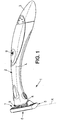
figure 1 is a perspective view of a safety razor, -
figure 2 is an exploded perspective view of the blade unit of the safety razor offigure 1 , not according to the invention, -
figure 3 is a perspective view of a cover seen from the bottom, -
figure 4 is a partial perspective view of a cutting member, -
figure 5 is a detail view of the application of the station ofFig. 6 to a cartridge, -
figure 6 is a schematic view of an ultrasonic welding station, -
figure 7 is a detail view ofFig. 5 , in cross-section along the symmetry axis of the cartridge, -
figure 8 is a graph of ultrasonic horn stroke (H) versus time, -
figure 9 is a partial cross section of the complete blade unit, taken along line IX-IX offigure 2 . - In the figures, the same references denote identical or similar elements.
-
Figure 1 shows a safety razor 1 (also called wet shaver), i.e. a shaver the blades of which are not driven by a motor relative to the blade unit. - The shaver 1 includes a
handle 2 extending in a longitudinal direction L between aproximal portion 3 and a distal portion 4 bearing ablade unit 5 or shaving head. The longitudinal direction L may be curved or include one or several straight portions. - The
blade unit 5 includes anupper face 6 equipped with one or several cutting members and a lower face 7 which is connected to the distal portion 4 of thehandle 2 by aconnection mechanism 8. Theconnection mechanism 8 may for instance enable theblade unit 5 to pivot relative to a pivot axis X which is substantially perpendicular to the longitudinal direction L. Said connection mechanism may further enable to selectively release the blade unit for the purpose of exchanging blade units. One particular example of connection mechanism usable in the present invention is described in documentWO-A-2006/027018 . - In the particular example shown in
figure 1 , thehandle 2 may further include an internal vibrating mechanism (not shown), which may be for instance as described in the above mentioned documentWO-A-2006/027018 and which is controlled by a user actuatedswitch 9. - Of course, the present invention is neither limited to such vibrating handle, nor to any particular connection mechanism connecting the
blade unit 5 to thehandle 2. - As shown in
figure 2 , theblade unit 5 includes aframe 10 which is made solely of synthetic materials, i.e. thermoplastic materials (polystyrene or ABS, for example) and elastomeric materials. - More precisely, the
frame 10 includes aplastic platform member 11 connected to thehandle 2 by theconnection mechanism 8 and having: - a
guard 12 extending parallel to the pivot axis X, - a
blade receiving section 13 situated rearward of theguard 12 in the direction of shaving, - a
cap portion 14 extending parallel to the pivot axis X and situated rearward of theblade receiving section 13 in the direction of shaving, - and two
side portions 15 joining the longitudinal ends of theguard 12 and of thecap portion 14 together. - Each of the
guard 12, thecap portion 14 and theside portions 15 have a top face (respectively 12a, 14a and 15a) visible onFig. 2 , and an opposite bottom face. These top faces 12a, 14a and 15a together form the so-called top face of the platform. - Each of the
side portions 15 has a raisedmiddle portion 53 level with theblade receiving section 13. - Further, the
cap portion 14 has two symmetricaltriangular lances 54 protruding from thetop face 14a of the cap portion. - In the example shown in the figures, the
guard 12 is covered by anelastomeric layer 16 forming a plurality offins 17 extending parallel to the pivot axis X. - Further, in this particular example, the underside of the
platform member 11 includes twoshell bearings 18 which belong to theconnection mechanism 8 and which may be for example as described in the above-mentioned documentWO-A-2006/027018 . - The
frame 10 further includes aplastic cover 19 having atop face 19a (visible onfigure 2 ) and anopposite bottom face 19b (seeFigure 3 ) which faces thetop face platform 11. Thecover 19 exhibits a general U shape, with acap portion 20 partially covering thecap portion 14 of the platform and twoside members 21 covering the twoside members 15 of the platform. In this embodiment, thecover 19 does no cover theguard 12 of the platform. - The
cap portion 20 of thecover 19 may include alubricating strip 23 which is oriented upward and comes into contact with the skin of the user during shaving. This lubricating strip may be formed for instance by co-injection with the rest of the cover. - As shown on
Fig. 3 , the vertical edge of theside members 21 of thecover 19 each comprise arecess 55 of shape complementary with the shape of the raisedportions 53 of theside members 15 of the platform.Further recesses 56 are formed in thebottom face 19a of thecap portion 20 of shapes which are complementary to the shapes of thelances 54 of thecap portion 14 of the platform. - Bonding
portions 57 are provided on thebottom face 19b of thecover 19, to be bonded with corresponding portions (not labelled) of theplatform 11. The corresponding portions of the platform are for example flat. Some of the bondingportions 57 are provided on the top face of theplatform 11, with the corresponding flat portion provided on the bottom face of the cover. - In the present example, bonding
portions 57 are provided symmetrically with respect to the symmetry axis of the cartridge. Two bondingportions 57 are provided each in one of the above-mentionedrecesses 55. Twoother bonding portions 57 are provided between therecesses 56 and the vertical edge of thecap portion 20 of the cover. Twoother bonding portions 57 are provided in the centre of thecap portion 20 of the cover. These two later bondingportions 57 are not aligned with the two previously described ones extending close to therecesses 56. - The
bonding portions 57 are for example provided as small parts of material, for example of triangular cross-section, and which are molded during the molding process of thecover 19. Their dimension and location might vary to the above-described ones, although the specifically described one was considered to achieve interesting results. - The
bonding portions 57 are each provided in a plane which is globally parallel to the plane. In the detailed example, thebonding portions 57 of thecap member 20 are provided in a plane parallel and distinct from the plane containing thebonding portions 57 of theside portions 21. Thus, efficient bonding is achieved. - As shown on
Figure 4 , at least one cuttingmember 24 is movably mounted in theblade receiving section 13 of the platform. Theblade receiving section 13 may include several cuttingmembers 24, for instance four cutting members as in the example shown in the drawings. - Each cutting
member 24 includes ablade 25 which is formed by a flat steel strip with acutting edge 26 oriented forward in the direction of shaving. Eachblade 25 has anupper face 27 oriented towards the skin to be shaved and alower face 28 oriented toward thehandle 2. The upper and lower faces 27, 28 of the blade include respectively two parallelmain surfaces facets edge 26. - Each
blade 25 extends longitudinally, parallel to the pivot axis X, between two lateral ends 33. - Each
blade 25 is borne by abent support 34. Thebent support 34 is a sheet metal part made out of steel with a bent profile including: - a substantially flat lower portion 35 (for example substantially perpendicular to the shaving plane),
- and a substantially flat
upper portion 39 which extends parallel to theblade 25. - The
blade 25 is fixed on theupper portion 39 of the bent support by any known means, for instance by laser spot welding. - The angle α of the
upper portion 39 and of theblade 25 with respect to the shaving plane may be around 22°. - The
lower portion 35 of thebent support 34 extends longitudinally, parallel to the pivot axis X, between twolateral portions 40. Eachlateral portion 40 includes aside edge 41. - Besides, the
upper portion 39 of the bent support extends longitudinally between two lateral edges each including a roundedprotrusion 42 which is constituted by a lateral wing with rounded angles protruding laterally from theupper portion 39 and from a correspondinglateral end 33 of the blade. - Further, a
rounded indent 43 is cut out from the sheet metal forming the blade support, said indent separating therounded protrusion 42 from thelateral edge 41 of the lower portion. - The side edges 41 of the lower portion of the bent support protrude laterally from the lateral ends 33 of the blade and from the rounded
protrusions 42. - The bent support may made from a flat sheet metal part which is then bent before welding of the
blade 25 on theupper portion 39 thereof. - As shown in
figure 2 , each cuttingmember 34 is borne by twoelastic fingers 44 which are molded as a single piece with theplatform 11 and which extend towards each other and upwardly from bothside members 15 of the platform. - Besides, as shown in
figure 2 , theend portions 40 of the bent supports are slidingly guided in vertical slots 45 (i.e. slots which are substantially perpendicular to the shaving plane) provided in the inner face of eachside member 15 of the platform. - The
blade members 24 are elastically biased by theelastical arms 44 toward a rest position. In this rest position, the upper faces 27 of the blades, at each lateral end of the blades, bear against correspondingupper stop portions 52 which are provided on thebottom face 19b of eachside member 21 of the cover, saidside member 21 covering the slots 45 (seeFigure 9 ). - Therefore, the rest position of the
blade members 24 is well defined, therefore enabling a high shaving precision. - As shown on
Figure 5 , anassembly 59 comprising theplatform 11, the cuttingmembers 24 inserted in theslots 45 and supported by theelastic fingers 44, and theunassembled cover 19 is provided into anest 80 displaced along a conveyingpath 81 to anultrasonic welding station 60 shown onFig. 6 . Theassembly 59 is displaced there by any suitable way. At this stage, thecover 19 faces upward and is supported on theplatform 11 by thelances 54 inserted in therecesses 56 and/or the raisedportions 53 inserted in therecesses 55. Thebottom face 19b of thecover 19 is distant from thetop face bonding portions 57. Still, the lateral sides 21 of thecover 19 work as stops for the cuttingmembers 24. - The
ultrasonic welding station 60 comprises the following elements: - a
base 61, which is underneath thenest 80 and support it during the ultrasonic welding, - a fixed
bracket 62, which is stationary and holds thebase 61, - a sliding
bracket 63 which slides along the vertical direction, thebracket 63 holding an ultrasonicbeam application device 64, to be described later in more details, - a
driving mechanism 65, which is for example driven by a motor (not shown), is carried by thesupport 62 and applies a periodic movement to the slidingbracket 63 relative to the fixedbracket 62. For example, thedriving mechanism 65 includes acam 66 having a specific cam profile which pushes oneend 67a of arod 67 which, at itsother end 67b, is connected to the slidingbracket 63 so that the sliding bracket performs a reversible motion (back and forth movement), - the ultrasonic
beam application device 64, - a power source, schematically shown as 68, providing suitable energy to the ultrasonic
beam application device 64, for example of 20 kHz and able to deliver 2kW. - The ultrasonic
beam application device 64 itself comprises aconverter 69, at which the ultrasonic electrical energy from thepower supply 68 is applied. The converter uses for example piezoelectric ceramic elements to transform the high frequency electrical oscillations into mechanical vibrations at the same frequency as the electrical oscillations. - The ultrasonic
beam application device 64 further comprises abooster 70 which is used as a mechanical transformer to modify the amplitude of vibrations applied to theassembly 59. The booster has for example a resonant half-wave section of titanium. It is mounted below the converter. It also provides a clamping point of the ultrasonicbeam application device 64 to thebracket 63. - The ultrasonic
beam application device 64 further comprises ahorn 71 tuned as a half-wave section and that applies the necessary force and vibration uniformly to the parts to be assembled. The horn is mounted to the booster. It transfers the ultrasonic vibrations from the converter (modified by the booster 70) to theassembly 59. The shape of the horn determines the amplitude at the face of the horn. The horn is for example designed to provide an amplitude of between 10 and 30 microns at a frequency of 20 kHz. - As shown on
Fig. 7 (the cross-section ofFig. 7 is taken along the symmetry line of the cover), thetip 82 of thehorn 71 has a vibration application device having aprofile 83 matching the profile of thecover 19. It has acentral portion 84 shaped to come in contact with thecap portion 20 of thecover 19, andlateral portions 85 shaped to come in contact with thelateral side portions 21 of the cover. - The
ultrasonic welding station 60 periodically operates as follows, in relation toFig. 8 , which plots the stroke (H) of the ultrasonicbeam application device 64 with respect to a reference as a function of time (for one cycle):
From point A to point F, the ultrasonicbeam application device 64 is held high, then rapidly moved down, then held, then slowly moved down, then held, then quickly moved up and held. From point A to point B, anew assembly 59 is brought to thebase station 61. At point B, the ultrasonicbeam application device 64 is then held low facing, with no contact, theassembly 59. - From point B to point C, the ultrasonic
beam application device 64 is slowly moved down until it contacts theassembly 59. - At point C, ultra-sonic vibrations are started.
- From point C to point D, ultra-sonic vibrations are locally focalised on the bonding portions (so-called "energy directors") 57 to generate mechanical vibrations at the interface between the platform and the cover, producing a sharp rise of temperature at the level of the
bonding portions 57. Vibrations are applied simultaneously to all thebonding portions 57, which melt. Some of the vibrations can be applied through the lubricatingstrip 23 of the cover (for thebonding portions 57 which are part of the cap portion of the cover). Bonding occurs only at thebonding portions 57, since there is a small gap between the upper face of the platform and the lower face of the cover outside the bonding portions. Continued pressure of about 14 kg is applied by thehorn 71 to thecover 19, by the continuous lowering of thehorn 71 to point D. The booster is set to operate at 1:1.5 and 60%, and the horn is set to apply an amplitude of 22 microns. An energy of 18 J is transferred to the assembly. The cover is lowered simultaneously to the horn, and is guided with respect to the platform by the cooperation of the guiding features 53, 54, 55, 56. - At point D, vibrations are stopped.
- From point D to point E, the
horn 71 is still in contact with thecover 19, while the molten materials cools down and solidifies, thereby achieving efficient bonding at thebonding portions 57. - From point E to point F, the
horn 71 is raised quickly and then held high while the bonded cartridge is removed from the station. - The cycle time of operation (between point A and point F) can be as low as 0.3 seconds, while still providing the expected results.
- Although a specific embodiment was disclosed above, it is believed that the parameters of the ultrasonic welding could be chosen in the following range, while still providing an efficient bonding process:
- Amplitude: 50 to 90%
- Frequency: 20 Khz
- Energy: 15 to 22 J
- Pressure: 10 to 16 Kg.
- Cycle time: 90 to 200 rotations per minute (rpm).
- After assembly, the
cap portion 20 of the cover forms, with thecap portion 14 of the platform, a cap 22 with comes into contact with the skin of the user during shaving. - Besides, the
side members 21 of the cover form, together with theside members 15 of the platform, two side portions of the frame, joining theguard 12 to the cap 22. During the shaving operation, the cuttingmembers 24 are guidedly movable relative to the platform. - It should be noted that, unlike laser welding, ultrasonic welding could be performed to weld together parts of the same color. Thus, there is no need for a pigment to be added in one of the parts to be welded, thereby leading to a product with good perceived quality.
Claims (14)
- A process for manufacturing a safety razor cartridge comprising:- providing an assembly (59) comprising:• a platform (11) having a top face (12a, 14a, 15a), the platform comprising a cap portion (14) and two lateral side portions (15),• at least one cutting member (24) extending between said lateral side portions (15) of the platform, said cutting member being supported by said platform, said cutting member (24) being movable with respect to said platform (15), said platform (11) and cutting member (24) cooperating to guide a movement of said cutting member with respect to the platform,• a cover (19) having a bottom face (19b) facing the top face of the platform, the cover comprising a cap portion (20) covering the cap portion (14) of the platform and two lateral side portions (21) covering the lateral side portions (15) of the platform,- welding the cover (19) to the platform by applying an ultrasonic beam to a plurality of discrete locations (57) of the assembly,wherein, before welding, both the top face of the platform (11) and the bottom face of the cover (19) have a plurality of discrete bonding portions (57) projecting from their respective faces, and wherein said ultrasonic beam is applied to said bonding portions (57) through the platform (11) and cover (19).
- Process according to claim 1 wherein the cap portion (14; 20) and both lateral side portion (15; 21) of at least one of the platform (11) and cover (14) each have at least one bonding portion (57).
- Process according to claim 1 or 2 wherein the cap portion (14; 20) of at least one of the platform (11) and cover (19) has at least three non-aligned bonding portions (57).
- Process according to any preceding claim, further having at least one of the following features:- the cover has a lubricating strip (23), and the ultrasonic beam is partly applied through the lubricating strip (23);- the cover (19) is provided having its two lateral side portion (21) partially covering the cutting members (24), and the cutting members (24) are biased in abutment with the cover (19);- an ultrasonic beam application device (64) is periodically moved between a first position enabling introduction and removal of an assembly (59) to a base station (61), and a second position in contact with the assembly to apply the ultrasonic beam to the assembly.
- A process according to any of claims 1-4, wherein the cap portion (20) of the cover is provided with bonding portions (57) in a first plane, wherein the side portion (21) of the cover are provided with bonding portions (57) in a second plane,
wherein said second plane is parallel to and distinct from the first plane. - A process according to any of claim 1-4, wherein the cap portion (14) of the platform is provided with bonding portions (57) in a first plane, wherein the side portions (15) of the platform are provided with bonding portions (57) in a second plane,
wherein said second plane is parallel and distinct from the first plane. - A safety razor cartridge comprising:- a platform (11) having a top face, the platform comprising a cap portion (14) and two lateral side portions (15),- at least one cutting member (24) extending between said lateral side portions (15) of the platform, said cutting member being supported by said platform, said cutting member being movable with respect to said platform, said platform (11) and cutting member (24) cooperating to guide a movement of said cutting member with respect to the platform,- a cover (19) having a bottom face facing the top face of the platform, the cover comprising a cap portion (20) covering the cap portion of the platform and two lateral side portions (21) covering the lateral side portions of the platform,- a plurality of discrete ultrasonic-welded bonding portions (57) between the cover and the platform, wherein some of the plurality of bonding portions (57) project from the top face of the platform (11) and some of the plurality of the bonding portions (57) project from the bottom face of the cover (19).
- A cartridge according to claim 7, wherein the bonding portion (57) are provided both at said cap portion (20) and said lateral side portions (21) of the cover.
- A cartridge according to claim 7 or 8, wherein the cover (19) is provided having its two lateral side portions (21) partially covering the cutting members (24), and wherein the cutting members are biased in abutment with the lateral side portions (21) of the cover.
- A cartridge according to any of claims 7 to 9, wherein the cutting members (24) comprise a razor blade (25) fixed on a L-shape metallic support (34).
- A cartridge according to any of claims 7 to 10, wherein the cover (19) and the platform (11) have mechanical guiding features (53, 54, 55, 56) of complementary shapes, adapted to guide a relative displacement of the cover and platform toward one another.
- A safety razor cartridge according to any of claims 7 to 11, wherein the cap portion (20) of the cover is provided with bonding portions (57) in a first plane, wherein the side portions (21) of the cover are provided with bonding portion (57) in a second plane,
wherein said second plane is parallel to and distinct from the first plane. - A safety razor cartridge according to any of claims 7 to 11, wherein the cap portion (14) of the platform is provided with bonding portions (57) in a first plane, wherein the side portions (15) of the platform are provided with bonding portions (57) in a second plane,
wherein said second plane is parallel to and distinct from the first plane. - A safety razor (1) comprising a cartridge according to any of claims 7 to 13.
Priority Applications (1)
| Application Number | Priority Date | Filing Date | Title |
|---|---|---|---|
| PL08786247T PL2307188T5 (en) | 2008-07-18 | 2008-07-18 | Process for manufacturing a safety razor cartridge, and safety razor cartridge |
Applications Claiming Priority (1)
| Application Number | Priority Date | Filing Date | Title |
|---|---|---|---|
| PCT/EP2008/059467 WO2010006654A1 (en) | 2008-07-18 | 2008-07-18 | Process and station for manufacturing a safety razor cartridge, and safety razor cartridge |
Publications (3)
| Publication Number | Publication Date |
|---|---|
| EP2307188A1 EP2307188A1 (en) | 2011-04-13 |
| EP2307188B1 EP2307188B1 (en) | 2015-07-08 |
| EP2307188B2 true EP2307188B2 (en) | 2018-09-12 |
Family
ID=40470925
Family Applications (1)
| Application Number | Title | Priority Date | Filing Date |
|---|---|---|---|
| EP08786247.0A Active EP2307188B2 (en) | 2008-07-18 | 2008-07-18 | Process for manufacturing a safety razor cartridge, and safety razor cartridge |
Country Status (7)
| Country | Link |
|---|---|
| US (1) | US9630330B2 (en) |
| EP (1) | EP2307188B2 (en) |
| BR (1) | BRPI0822858B1 (en) |
| CA (1) | CA2730640C (en) |
| MX (1) | MX349201B (en) |
| PL (1) | PL2307188T5 (en) |
| WO (1) | WO2010006654A1 (en) |
Families Citing this family (24)
| Publication number | Priority date | Publication date | Assignee | Title |
|---|---|---|---|---|
| US8307553B2 (en) * | 2008-05-01 | 2012-11-13 | Eveready Battery Company, Inc. | Razor cartridge |
| EP2268463B1 (en) * | 2008-05-01 | 2012-10-10 | Eveready Battery Company, Inc. | Separable lubrication |
| WO2010006654A1 (en) * | 2008-07-18 | 2010-01-21 | Bic-Violex Sa | Process and station for manufacturing a safety razor cartridge, and safety razor cartridge |
| EP2419247B1 (en) * | 2009-04-15 | 2020-05-27 | BIC-Violex S.A. | Method of manufacturing a razor head component, support obtained thereby and razor cartridge and razor comprising said support |
| KR101351093B1 (en) * | 2010-08-02 | 2014-01-14 | 삼성전자주식회사 | A Blowing Fan and Vibration Absorbing Boss thereof |
| MX376361B (en) | 2011-10-06 | 2025-03-07 | Bic Violex Sa | RAZOR BLADE, RAZOR HEAD AND MANUFACTURING METHODS. |
| EP3178621A1 (en) | 2011-10-06 | 2017-06-14 | BIC-Violex S.A. | Razor head having a low shaving angle |
| PL3378614T3 (en) | 2011-10-06 | 2020-12-14 | Bic-Violex S.A. | Razor blade, razor head, and method of manufacture |
| KR101991472B1 (en) | 2012-09-26 | 2019-09-30 | 빅-비올렉스 에스아 | Method and system for the manufacture of a razor cartridge |
| US20140123506A1 (en) * | 2012-11-07 | 2014-05-08 | Mark Gaines | Razor with Safety Features for Use in a Correctional Facility |
| CN106029311B (en) | 2013-12-18 | 2019-07-16 | 比克-维尔莱克 | Razor holder |
| MX383370B (en) * | 2014-03-05 | 2025-03-13 | Mack Ray Inc | DOUBLE-EDGE RAZOR. |
| KR102712230B1 (en) * | 2015-12-17 | 2024-09-30 | 빅 비올렉스 싱글 멤버 에스.아. | Shaving head |
| WO2017103882A1 (en) * | 2015-12-17 | 2017-06-22 | Bic Violex S.A. | Shaving head |
| CN109414828B (en) | 2016-03-18 | 2020-12-18 | 个人护理市场及调研公司 | razor box |
| US9993931B1 (en) | 2016-11-23 | 2018-06-12 | Personal Care Marketing And Research, Inc. | Razor docking and pivot |
| KR101746387B1 (en) * | 2016-11-24 | 2017-06-14 | 주식회사 도루코 | Unitary razor cartridge |
| CN107414903A (en) * | 2017-08-02 | 2017-12-01 | 宁波美猴王剃须刀有限公司 | Bending razor blade and its fixed seat for coordinating installation |
| EP3663033A1 (en) * | 2018-12-06 | 2020-06-10 | BIC-Violex S.A. | Laser welded razor blades |
| USD884970S1 (en) | 2019-02-27 | 2020-05-19 | PCMR International Ltd. | Razor cartridge guard |
| USD884971S1 (en) | 2019-02-27 | 2020-05-19 | Pcmr International Ltd | Razor cartridge |
| USD884969S1 (en) | 2019-02-27 | 2020-05-19 | Pcmr International Ltd | Combined razor cartridge guard and docking |
| US11000960B1 (en) | 2020-11-16 | 2021-05-11 | Personal Care Marketing And Research, Inc. | Razor exposure |
| KR102898119B1 (en) * | 2023-06-09 | 2025-12-09 | 주식회사 도루코 | Razor Cartridge |
Family Cites Families (41)
| Publication number | Priority date | Publication date | Assignee | Title |
|---|---|---|---|---|
| GB1163222A (en) * | 1967-06-19 | 1969-09-04 | Gillette Industries Ltd | Improvements relating to Safety Razors |
| GB1251905A (en) | 1969-11-11 | 1971-11-03 | ||
| GB1417831A (en) | 1971-10-22 | 1975-12-17 | Warner Lambert Co | Razor blade cartridge dispensing systems |
| GB1378085A (en) | 1972-05-16 | 1974-12-18 | Wilkinson Sword Ltd | Shaving devices |
| US3815233A (en) * | 1972-09-05 | 1974-06-11 | Woodmont Ind Inc | Shaving cartridges |
| GB2164597B (en) * | 1984-09-20 | 1988-02-10 | Wilkinson Sword Ltd | An improved razor blade assembly and its method of manufacture |
| US4852254A (en) * | 1984-09-20 | 1989-08-01 | Wilkinson Sword Limited | Razor blade assembly and its method of manufacture |
| AU638974B2 (en) * | 1989-06-05 | 1993-07-15 | Warner-Lambert Company | Razor mechanism |
| DE8909759U1 (en) | 1989-08-16 | 1990-12-20 | Wilkinson Sword GmbH, 5650 Solingen | Shaver head, in particular razor blade unit of a wet shaver |
| DE3926899A1 (en) * | 1989-08-16 | 1991-02-21 | Wilkinson Sword Gmbh | SHAVER HEAD, ESPECIALLY RAZOR BLADE UNIT OF A WET SHAVER |
| US5157834A (en) * | 1990-04-10 | 1992-10-27 | Warner-Lambert Company | Razor mechanism with slidable cartridge support |
| JPH0462383A (en) | 1990-06-29 | 1992-02-27 | Iseki & Co Ltd | Operating control method of grain preparatory processing apparatus |
| SE9303693L (en) * | 1993-11-09 | 1994-10-17 | Moelnlycke Ab | Method and apparatus for ultrasonic welding at high running speeds of the material webs |
| DK0784530T3 (en) | 1994-10-03 | 2000-05-01 | Gillette Co | A razor |
| US5943781A (en) * | 1996-01-03 | 1999-08-31 | Violex-Bic S.A. | Safety razor blade tool |
| WO1997035693A2 (en) * | 1996-03-27 | 1997-10-02 | Warner-Lambert Company | Shaving system with uniform shaving forces |
| US5956849A (en) * | 1997-06-05 | 1999-09-28 | Bic Corporation | Lubricating shaving aid |
| US20030159291A1 (en) * | 1997-07-25 | 2003-08-28 | Gregory Clark | Shaving system with uniform shaving forces |
| DE69806026T2 (en) * | 1997-09-18 | 2002-10-31 | The Gillette Co., Boston | SAFETY SHAVER |
| US6009624A (en) * | 1997-09-30 | 2000-01-04 | The Gillette Company | Razor cartridge with movable blades |
| FR2769535B1 (en) | 1997-10-15 | 1999-12-31 | Bic Soc | EXTRUDED ANTIFRICTION STRIP FOR SHAVING HEAD AND SHAVING HEAD COMPRISING SUCH A STRIP |
| US6115902A (en) * | 1998-02-13 | 2000-09-12 | Bic Corporation | Method of manufacturing a razor |
| FR2793435B1 (en) | 1999-05-12 | 2001-08-03 | Bic Rech Et Dev | RAZOR HEAD COMPRISING AN SOLIDARITY ANTI-FRICTION ELEMENT OF A SOLE |
| US6868082B1 (en) | 1999-08-30 | 2005-03-15 | International Business Machines Corporation | Network processor interface for building scalable switching systems |
| KR100669144B1 (en) * | 1999-11-29 | 2007-01-15 | 코닌클리케 필립스 일렉트로닉스 엔.브이. | Shaver with shaving head with sub-frame and main frame |
| GB2408010B (en) * | 2003-11-17 | 2007-03-28 | Knowledge & Merchandising Inc | Shaving product |
| BRPI0418796A (en) | 2004-05-06 | 2007-10-09 | Bic Violex Sa | shaver head having laser welded parts and method of production thereof |
| EP1789238B1 (en) * | 2004-09-07 | 2008-03-19 | BIC Violex S.A. | Razor handle and shaver including such a handle |
| EP1796883B2 (en) * | 2004-10-04 | 2010-12-29 | BIC Violex S.A. | Vibrating wet shaver |
| US20090119924A1 (en) * | 2005-09-06 | 2009-05-14 | Ioannis Bozikis | Vibrating wet shaver |
| US20070050995A1 (en) * | 2005-09-06 | 2007-03-08 | Fred Schnak | Razors |
| US7331107B2 (en) * | 2005-12-20 | 2008-02-19 | Eveready Battery Company, Inc. | Pivot axis for a shaving cartridge |
| CA2655513C (en) * | 2006-06-20 | 2012-01-03 | Bic-Violex S.A. | Razor blade unit head and safety razor including such a blade unit |
| US7581318B2 (en) * | 2006-08-03 | 2009-09-01 | Eveready Battery Company, Inc. | Skin engaging device for a safety razor |
| GB0716941D0 (en) * | 2007-08-31 | 2007-10-10 | Knowledge & Merchandising Inc | Razor handle |
| US7665199B2 (en) | 2008-01-23 | 2010-02-23 | The Gillette Company | Method of making a razor blade unit |
| US8307553B2 (en) * | 2008-05-01 | 2012-11-13 | Eveready Battery Company, Inc. | Razor cartridge |
| ES2383167T3 (en) * | 2008-05-22 | 2012-06-18 | Feintechnik Gmbh Eisfeld | Razor blade unit with cutting edge housing |
| WO2010006654A1 (en) * | 2008-07-18 | 2010-01-21 | Bic-Violex Sa | Process and station for manufacturing a safety razor cartridge, and safety razor cartridge |
| US9156174B2 (en) * | 2008-12-19 | 2015-10-13 | Bic-Violex S.A. | Razor cartridge and mechanical razor comprising such a cartridge |
| WO2010069389A1 (en) * | 2008-12-19 | 2010-06-24 | Bic-Violex Sa | Method and apparatus for the manufacture of razor head component, and components thus manufactured |
-
2008
- 2008-07-18 WO PCT/EP2008/059467 patent/WO2010006654A1/en not_active Ceased
- 2008-07-18 PL PL08786247T patent/PL2307188T5/en unknown
- 2008-07-18 US US13/054,758 patent/US9630330B2/en active Active
- 2008-07-18 EP EP08786247.0A patent/EP2307188B2/en active Active
- 2008-07-18 BR BRPI0822858A patent/BRPI0822858B1/en not_active IP Right Cessation
- 2008-07-18 CA CA2730640A patent/CA2730640C/en not_active Expired - Fee Related
- 2008-07-18 MX MX2011000057A patent/MX349201B/en active IP Right Grant
Also Published As
| Publication number | Publication date |
|---|---|
| MX2011000057A (en) | 2011-05-30 |
| EP2307188A1 (en) | 2011-04-13 |
| PL2307188T5 (en) | 2019-02-28 |
| BRPI0822858A2 (en) | 2015-06-30 |
| EP2307188B1 (en) | 2015-07-08 |
| CA2730640C (en) | 2016-05-31 |
| WO2010006654A1 (en) | 2010-01-21 |
| BRPI0822858B1 (en) | 2020-04-28 |
| US9630330B2 (en) | 2017-04-25 |
| MX349201B (en) | 2017-07-17 |
| US20110119922A1 (en) | 2011-05-26 |
| CA2730640A1 (en) | 2010-01-21 |
| PL2307188T3 (en) | 2015-12-31 |
Similar Documents
| Publication | Publication Date | Title |
|---|---|---|
| EP2307188B1 (en) | Process for manufacturing a safety razor cartridge, and safety razor cartridge | |
| US9533424B2 (en) | Razor handle | |
| JP6332892B2 (en) | Fixed blade, blade set, and hair cutting equipment | |
| EP0462807B1 (en) | Process for insert molding wet-shaving razor unit and unit made therefrom | |
| JP6758012B2 (en) | Ultrasonic welding method, ultrasonic welding equipment | |
| CN102300683B (en) | Razor cartridge holder and mechanical razor including the cartridge holder | |
| KR101621034B1 (en) | Razor cartridge and mechanical razor comprising such a cartridge | |
| CN105916658B (en) | Design of Energy Director Joints for Ultrasonic Welding of Thermoplastics | |
| CN212684032U (en) | Shaver head and shaver | |
| CN101255652A (en) | Zipper Cutting Mechanism | |
| CN102281963A (en) | Method and apparatus for making razor head assemblies and assemblies made thereby | |
| US12583185B2 (en) | Ultrasonic and vibration welding of thermoplastics using a vibratable tool | |
| JP2013031537A (en) | Brush and method for manufacturing the same | |
| JPH0436541B2 (en) | ||
| JP6052542B2 (en) | Slit blade block and blade unit and electric razor | |
| CN224129847U (en) | Cutting smooth cutter head structure and hair trimmer | |
| KR102936692B1 (en) | Razor cartridge | |
| JPH0436540B2 (en) | ||
| JPH0513053B2 (en) | ||
| CN116417284A (en) | Electromagnetic relay with arc extinguishing function | |
| CN113771102A (en) | Blade structure, blade unit structure, shaving head and shaving device | |
| CN113752305A (en) | Blade unit structure and method, novel blade holder and shaving device | |
| KR20010114119A (en) | Fan, method and apparatus of making the same | |
| JP2006015437A (en) | Method for cutting resin molded body and apparatus for cutting resin molded body | |
| JPH105459A (en) | Electric razor |
Legal Events
| Date | Code | Title | Description |
|---|---|---|---|
| PUAI | Public reference made under article 153(3) epc to a published international application that has entered the european phase |
Free format text: ORIGINAL CODE: 0009012 |
|
| 17P | Request for examination filed |
Effective date: 20101213 |
|
| AK | Designated contracting states |
Kind code of ref document: A1 Designated state(s): AT BE BG CH CY CZ DE DK EE ES FI FR GB GR HR HU IE IS IT LI LT LU LV MC MT NL NO PL PT RO SE SI SK TR |
|
| AX | Request for extension of the european patent |
Extension state: AL BA MK RS |
|
| DAX | Request for extension of the european patent (deleted) | ||
| 17Q | First examination report despatched |
Effective date: 20140801 |
|
| GRAP | Despatch of communication of intention to grant a patent |
Free format text: ORIGINAL CODE: EPIDOSNIGR1 |
|
| INTG | Intention to grant announced |
Effective date: 20150204 |
|
| RIN1 | Information on inventor provided before grant (corrected) |
Inventor name: KOULOURIAS, GEORGIOS Inventor name: NTAVOS, VASILEIOS |
|
| GRAS | Grant fee paid |
Free format text: ORIGINAL CODE: EPIDOSNIGR3 |
|
| GRAA | (expected) grant |
Free format text: ORIGINAL CODE: 0009210 |
|
| REG | Reference to a national code |
Ref country code: FR Ref legal event code: PLFP Year of fee payment: 8 |
|
| AK | Designated contracting states |
Kind code of ref document: B1 Designated state(s): AT BE BG CH CY CZ DE DK EE ES FI FR GB GR HR HU IE IS IT LI LT LU LV MC MT NL NO PL PT RO SE SI SK TR |
|
| REG | Reference to a national code |
Ref country code: GB Ref legal event code: FG4D |
|
| REG | Reference to a national code |
Ref country code: AT Ref legal event code: REF Ref document number: 735049 Country of ref document: AT Kind code of ref document: T Effective date: 20150715 Ref country code: CH Ref legal event code: EP |
|
| REG | Reference to a national code |
Ref country code: IE Ref legal event code: FG4D |
|
| REG | Reference to a national code |
Ref country code: DE Ref legal event code: R096 Ref document number: 602008038945 Country of ref document: DE |
|
| REG | Reference to a national code |
Ref country code: GR Ref legal event code: EP Ref document number: 20150401633 Country of ref document: GR Effective date: 20150929 |
|
| REG | Reference to a national code |
Ref country code: AT Ref legal event code: MK05 Ref document number: 735049 Country of ref document: AT Kind code of ref document: T Effective date: 20150708 |
|
| REG | Reference to a national code |
Ref country code: NL Ref legal event code: MP Effective date: 20150708 |
|
| REG | Reference to a national code |
Ref country code: LT Ref legal event code: MG4D |
|
| REG | Reference to a national code |
Ref country code: PL Ref legal event code: T3 |
|
| PG25 | Lapsed in a contracting state [announced via postgrant information from national office to epo] |
Ref country code: LV Free format text: LAPSE BECAUSE OF FAILURE TO SUBMIT A TRANSLATION OF THE DESCRIPTION OR TO PAY THE FEE WITHIN THE PRESCRIBED TIME-LIMIT Effective date: 20150708 Ref country code: LT Free format text: LAPSE BECAUSE OF FAILURE TO SUBMIT A TRANSLATION OF THE DESCRIPTION OR TO PAY THE FEE WITHIN THE PRESCRIBED TIME-LIMIT Effective date: 20150708 Ref country code: FI Free format text: LAPSE BECAUSE OF FAILURE TO SUBMIT A TRANSLATION OF THE DESCRIPTION OR TO PAY THE FEE WITHIN THE PRESCRIBED TIME-LIMIT Effective date: 20150708 Ref country code: NO Free format text: LAPSE BECAUSE OF FAILURE TO SUBMIT A TRANSLATION OF THE DESCRIPTION OR TO PAY THE FEE WITHIN THE PRESCRIBED TIME-LIMIT Effective date: 20151008 |
|
| PG25 | Lapsed in a contracting state [announced via postgrant information from national office to epo] |
Ref country code: PT Free format text: LAPSE BECAUSE OF FAILURE TO SUBMIT A TRANSLATION OF THE DESCRIPTION OR TO PAY THE FEE WITHIN THE PRESCRIBED TIME-LIMIT Effective date: 20151109 Ref country code: HR Free format text: LAPSE BECAUSE OF FAILURE TO SUBMIT A TRANSLATION OF THE DESCRIPTION OR TO PAY THE FEE WITHIN THE PRESCRIBED TIME-LIMIT Effective date: 20150708 Ref country code: IS Free format text: LAPSE BECAUSE OF FAILURE TO SUBMIT A TRANSLATION OF THE DESCRIPTION OR TO PAY THE FEE WITHIN THE PRESCRIBED TIME-LIMIT Effective date: 20151108 Ref country code: SE Free format text: LAPSE BECAUSE OF FAILURE TO SUBMIT A TRANSLATION OF THE DESCRIPTION OR TO PAY THE FEE WITHIN THE PRESCRIBED TIME-LIMIT Effective date: 20150708 Ref country code: ES Free format text: LAPSE BECAUSE OF FAILURE TO SUBMIT A TRANSLATION OF THE DESCRIPTION OR TO PAY THE FEE WITHIN THE PRESCRIBED TIME-LIMIT Effective date: 20150708 Ref country code: AT Free format text: LAPSE BECAUSE OF FAILURE TO SUBMIT A TRANSLATION OF THE DESCRIPTION OR TO PAY THE FEE WITHIN THE PRESCRIBED TIME-LIMIT Effective date: 20150708 |
|
| REG | Reference to a national code |
Ref country code: CH Ref legal event code: PL |
|
| REG | Reference to a national code |
Ref country code: DE Ref legal event code: R026 Ref document number: 602008038945 Country of ref document: DE |
|
| PLBI | Opposition filed |
Free format text: ORIGINAL CODE: 0009260 |
|
| REG | Reference to a national code |
Ref country code: IE Ref legal event code: MM4A |
|
| PG25 | Lapsed in a contracting state [announced via postgrant information from national office to epo] |
Ref country code: EE Free format text: LAPSE BECAUSE OF FAILURE TO SUBMIT A TRANSLATION OF THE DESCRIPTION OR TO PAY THE FEE WITHIN THE PRESCRIBED TIME-LIMIT Effective date: 20150708 Ref country code: DK Free format text: LAPSE BECAUSE OF FAILURE TO SUBMIT A TRANSLATION OF THE DESCRIPTION OR TO PAY THE FEE WITHIN THE PRESCRIBED TIME-LIMIT Effective date: 20150708 Ref country code: CZ Free format text: LAPSE BECAUSE OF FAILURE TO SUBMIT A TRANSLATION OF THE DESCRIPTION OR TO PAY THE FEE WITHIN THE PRESCRIBED TIME-LIMIT Effective date: 20150708 Ref country code: SK Free format text: LAPSE BECAUSE OF FAILURE TO SUBMIT A TRANSLATION OF THE DESCRIPTION OR TO PAY THE FEE WITHIN THE PRESCRIBED TIME-LIMIT Effective date: 20150708 Ref country code: CH Free format text: LAPSE BECAUSE OF NON-PAYMENT OF DUE FEES Effective date: 20150731 Ref country code: LI Free format text: LAPSE BECAUSE OF NON-PAYMENT OF DUE FEES Effective date: 20150731 Ref country code: MC Free format text: LAPSE BECAUSE OF FAILURE TO SUBMIT A TRANSLATION OF THE DESCRIPTION OR TO PAY THE FEE WITHIN THE PRESCRIBED TIME-LIMIT Effective date: 20150708 |
|
| 26 | Opposition filed |
Opponent name: EDGEWELL PERSONAL CARE BRANDS, LLC Effective date: 20160406 |
|
| PLAX | Notice of opposition and request to file observation + time limit sent |
Free format text: ORIGINAL CODE: EPIDOSNOBS2 |
|
| PG25 | Lapsed in a contracting state [announced via postgrant information from national office to epo] |
Ref country code: RO Free format text: LAPSE BECAUSE OF FAILURE TO SUBMIT A TRANSLATION OF THE DESCRIPTION OR TO PAY THE FEE WITHIN THE PRESCRIBED TIME-LIMIT Effective date: 20150708 |
|
| REG | Reference to a national code |
Ref country code: FR Ref legal event code: PLFP Year of fee payment: 9 |
|
| PG25 | Lapsed in a contracting state [announced via postgrant information from national office to epo] |
Ref country code: IE Free format text: LAPSE BECAUSE OF NON-PAYMENT OF DUE FEES Effective date: 20150718 |
|
| PG25 | Lapsed in a contracting state [announced via postgrant information from national office to epo] |
Ref country code: SI Free format text: LAPSE BECAUSE OF FAILURE TO SUBMIT A TRANSLATION OF THE DESCRIPTION OR TO PAY THE FEE WITHIN THE PRESCRIBED TIME-LIMIT Effective date: 20150708 |
|
| PLAF | Information modified related to communication of a notice of opposition and request to file observations + time limit |
Free format text: ORIGINAL CODE: EPIDOSCOBS2 |
|
| PLBB | Reply of patent proprietor to notice(s) of opposition received |
Free format text: ORIGINAL CODE: EPIDOSNOBS3 |
|
| PG25 | Lapsed in a contracting state [announced via postgrant information from national office to epo] |
Ref country code: BE Free format text: LAPSE BECAUSE OF FAILURE TO SUBMIT A TRANSLATION OF THE DESCRIPTION OR TO PAY THE FEE WITHIN THE PRESCRIBED TIME-LIMIT Effective date: 20150708 |
|
| PG25 | Lapsed in a contracting state [announced via postgrant information from national office to epo] |
Ref country code: MT Free format text: LAPSE BECAUSE OF FAILURE TO SUBMIT A TRANSLATION OF THE DESCRIPTION OR TO PAY THE FEE WITHIN THE PRESCRIBED TIME-LIMIT Effective date: 20150708 |
|
| PG25 | Lapsed in a contracting state [announced via postgrant information from national office to epo] |
Ref country code: BG Free format text: LAPSE BECAUSE OF FAILURE TO SUBMIT A TRANSLATION OF THE DESCRIPTION OR TO PAY THE FEE WITHIN THE PRESCRIBED TIME-LIMIT Effective date: 20150708 Ref country code: HU Free format text: LAPSE BECAUSE OF FAILURE TO SUBMIT A TRANSLATION OF THE DESCRIPTION OR TO PAY THE FEE WITHIN THE PRESCRIBED TIME-LIMIT; INVALID AB INITIO Effective date: 20080718 |
|
| PG25 | Lapsed in a contracting state [announced via postgrant information from national office to epo] |
Ref country code: NL Free format text: LAPSE BECAUSE OF FAILURE TO SUBMIT A TRANSLATION OF THE DESCRIPTION OR TO PAY THE FEE WITHIN THE PRESCRIBED TIME-LIMIT Effective date: 20150708 Ref country code: CY Free format text: LAPSE BECAUSE OF FAILURE TO SUBMIT A TRANSLATION OF THE DESCRIPTION OR TO PAY THE FEE WITHIN THE PRESCRIBED TIME-LIMIT Effective date: 20150708 |
|
| REG | Reference to a national code |
Ref country code: FR Ref legal event code: PLFP Year of fee payment: 10 |
|
| RIC2 | Information provided on ipc code assigned after grant |
Ipc: B29C 65/08 20060101AFI20171020BHEP Ipc: B26B 21/40 20060101ALI20171020BHEP Ipc: B26B 21/22 20060101ALI20171020BHEP |
|
| PG25 | Lapsed in a contracting state [announced via postgrant information from national office to epo] |
Ref country code: LU Free format text: LAPSE BECAUSE OF NON-PAYMENT OF DUE FEES Effective date: 20150718 |
|
| APBM | Appeal reference recorded |
Free format text: ORIGINAL CODE: EPIDOSNREFNO |
|
| APBP | Date of receipt of notice of appeal recorded |
Free format text: ORIGINAL CODE: EPIDOSNNOA2O |
|
| APAH | Appeal reference modified |
Free format text: ORIGINAL CODE: EPIDOSCREFNO |
|
| APBU | Appeal procedure closed |
Free format text: ORIGINAL CODE: EPIDOSNNOA9O |
|
| REG | Reference to a national code |
Ref country code: FR Ref legal event code: PLFP Year of fee payment: 11 |
|
| PUAH | Patent maintained in amended form |
Free format text: ORIGINAL CODE: 0009272 |
|
| STAA | Information on the status of an ep patent application or granted ep patent |
Free format text: STATUS: PATENT MAINTAINED AS AMENDED |
|
| 27A | Patent maintained in amended form |
Effective date: 20180912 |
|
| AK | Designated contracting states |
Kind code of ref document: B2 Designated state(s): AT BE BG CH CY CZ DE DK EE ES FI FR GB GR HR HU IE IS IT LI LT LU LV MC MT NL NO PL PT RO SE SI SK TR |
|
| REG | Reference to a national code |
Ref country code: DE Ref legal event code: R102 Ref document number: 602008038945 Country of ref document: DE |
|
| REG | Reference to a national code |
Ref country code: GR Ref legal event code: EP Ref document number: 20180403575 Country of ref document: GR Effective date: 20190404 |
|
| PGFP | Annual fee paid to national office [announced via postgrant information from national office to epo] |
Ref country code: IT Payment date: 20190624 Year of fee payment: 12 |
|
| PG25 | Lapsed in a contracting state [announced via postgrant information from national office to epo] |
Ref country code: IT Free format text: LAPSE BECAUSE OF NON-PAYMENT OF DUE FEES Effective date: 20200718 |
|
| PGFP | Annual fee paid to national office [announced via postgrant information from national office to epo] |
Ref country code: GB Payment date: 20240620 Year of fee payment: 17 |
|
| PGFP | Annual fee paid to national office [announced via postgrant information from national office to epo] |
Ref country code: GR Payment date: 20240620 Year of fee payment: 17 |
|
| PGFP | Annual fee paid to national office [announced via postgrant information from national office to epo] |
Ref country code: DE Payment date: 20250722 Year of fee payment: 18 |
|
| PGFP | Annual fee paid to national office [announced via postgrant information from national office to epo] |
Ref country code: TR Payment date: 20250711 Year of fee payment: 18 Ref country code: PL Payment date: 20250704 Year of fee payment: 18 |
|
| PGFP | Annual fee paid to national office [announced via postgrant information from national office to epo] |
Ref country code: FR Payment date: 20250723 Year of fee payment: 18 |
|
| GBPC | Gb: european patent ceased through non-payment of renewal fee |
Effective date: 20250718 |
|
| PG25 | Lapsed in a contracting state [announced via postgrant information from national office to epo] |
Ref country code: GB Free format text: LAPSE BECAUSE OF NON-PAYMENT OF DUE FEES Effective date: 20250718 |
|
| PG25 | Lapsed in a contracting state [announced via postgrant information from national office to epo] |
Ref country code: GR Free format text: LAPSE BECAUSE OF NON-PAYMENT OF DUE FEES Effective date: 20260204 |