EP2306791A2 - Dimming a multi-lamp fluorescent light fixture by turning off an individual lamp using a wireless fluorescent lamp starter - Google Patents
Dimming a multi-lamp fluorescent light fixture by turning off an individual lamp using a wireless fluorescent lamp starter Download PDFInfo
- Publication number
- EP2306791A2 EP2306791A2 EP10185267A EP10185267A EP2306791A2 EP 2306791 A2 EP2306791 A2 EP 2306791A2 EP 10185267 A EP10185267 A EP 10185267A EP 10185267 A EP10185267 A EP 10185267A EP 2306791 A2 EP2306791 A2 EP 2306791A2
- Authority
- EP
- European Patent Office
- Prior art keywords
- lamp
- starter
- starter unit
- dimmer
- turning
- Prior art date
- Legal status (The legal status is an assumption and is not a legal conclusion. Google has not performed a legal analysis and makes no representation as to the accuracy of the status listed.)
- Granted
Links
Images


Classifications
-
- H—ELECTRICITY
- H05—ELECTRIC TECHNIQUES NOT OTHERWISE PROVIDED FOR
- H05B—ELECTRIC HEATING; ELECTRIC LIGHT SOURCES NOT OTHERWISE PROVIDED FOR; CIRCUIT ARRANGEMENTS FOR ELECTRIC LIGHT SOURCES, IN GENERAL
- H05B41/00—Circuit arrangements or apparatus for igniting or operating discharge lamps
- H05B41/02—Details
- H05B41/04—Starting switches
- H05B41/042—Starting switches using semiconductor devices
- H05B41/044—Starting switches using semiconductor devices for lamp provided with pre-heating electrodes
- H05B41/046—Starting switches using semiconductor devices for lamp provided with pre-heating electrodes using controlled semiconductor devices
-
- H—ELECTRICITY
- H05—ELECTRIC TECHNIQUES NOT OTHERWISE PROVIDED FOR
- H05B—ELECTRIC HEATING; ELECTRIC LIGHT SOURCES NOT OTHERWISE PROVIDED FOR; CIRCUIT ARRANGEMENTS FOR ELECTRIC LIGHT SOURCES, IN GENERAL
- H05B41/00—Circuit arrangements or apparatus for igniting or operating discharge lamps
- H05B41/14—Circuit arrangements
- H05B41/36—Controlling
- H05B41/38—Controlling the intensity of light
- H05B41/39—Controlling the intensity of light continuously
- H05B41/392—Controlling the intensity of light continuously using semiconductor devices, e.g. thyristor
-
- H—ELECTRICITY
- H05—ELECTRIC TECHNIQUES NOT OTHERWISE PROVIDED FOR
- H05B—ELECTRIC HEATING; ELECTRIC LIGHT SOURCES NOT OTHERWISE PROVIDED FOR; CIRCUIT ARRANGEMENTS FOR ELECTRIC LIGHT SOURCES, IN GENERAL
- H05B47/00—Circuit arrangements for operating light sources in general, i.e. where the type of light source is not relevant
- H05B47/10—Controlling the light source
- H05B47/105—Controlling the light source in response to determined parameters
- H05B47/115—Controlling the light source in response to determined parameters by determining the presence or movement of objects or living beings
-
- H—ELECTRICITY
- H05—ELECTRIC TECHNIQUES NOT OTHERWISE PROVIDED FOR
- H05B—ELECTRIC HEATING; ELECTRIC LIGHT SOURCES NOT OTHERWISE PROVIDED FOR; CIRCUIT ARRANGEMENTS FOR ELECTRIC LIGHT SOURCES, IN GENERAL
- H05B47/00—Circuit arrangements for operating light sources in general, i.e. where the type of light source is not relevant
- H05B47/10—Controlling the light source
- H05B47/175—Controlling the light source by remote control
- H05B47/19—Controlling the light source by remote control via wireless transmission
-
- H—ELECTRICITY
- H05—ELECTRIC TECHNIQUES NOT OTHERWISE PROVIDED FOR
- H05B—ELECTRIC HEATING; ELECTRIC LIGHT SOURCES NOT OTHERWISE PROVIDED FOR; CIRCUIT ARRANGEMENTS FOR ELECTRIC LIGHT SOURCES, IN GENERAL
- H05B47/00—Circuit arrangements for operating light sources in general, i.e. where the type of light source is not relevant
- H05B47/10—Controlling the light source
- H05B47/105—Controlling the light source in response to determined parameters
- H05B47/115—Controlling the light source in response to determined parameters by determining the presence or movement of objects or living beings
- H05B47/13—Controlling the light source in response to determined parameters by determining the presence or movement of objects or living beings by using passive infrared detectors
-
- Y—GENERAL TAGGING OF NEW TECHNOLOGICAL DEVELOPMENTS; GENERAL TAGGING OF CROSS-SECTIONAL TECHNOLOGIES SPANNING OVER SEVERAL SECTIONS OF THE IPC; TECHNICAL SUBJECTS COVERED BY FORMER USPC CROSS-REFERENCE ART COLLECTIONS [XRACs] AND DIGESTS
- Y02—TECHNOLOGIES OR APPLICATIONS FOR MITIGATION OR ADAPTATION AGAINST CLIMATE CHANGE
- Y02B—CLIMATE CHANGE MITIGATION TECHNOLOGIES RELATED TO BUILDINGS, e.g. HOUSING, HOUSE APPLIANCES OR RELATED END-USER APPLICATIONS
- Y02B20/00—Energy efficient lighting technologies, e.g. halogen lamps or gas discharge lamps
- Y02B20/40—Control techniques providing energy savings, e.g. smart controller or presence detection
Definitions
- the described embodiments relate to starter units for fluorescent lamps.
- a multi-lamp fluorescent light fixture involves a number of tubular fluorescent bulbs. Each fluorescent bulb is also referred to here as a fluorescent lamp. Each tube is a glass tube that contains an ionizable gas and a small portion of mercury. There are filaments at each end of the tube. By application of proper electrical voltages, the filaments can be made to heat up and to ionize the ionizable gas in the tube. After sufficient heating, if a voltage of adequate magnitude is subsequently provided between the filaments, an electrical arc can be initiated through the ionized gas in the tube between the filaments. The arc involves a flow of current from one filament, through the ionized gas, to the other filament.
- Energetic electrons in this current flow collide with the mercury atoms, thereby exciting the mercury atoms and causing them to emit ultraviolet radiation.
- the emitted ultraviolet radiation is absorbed by and excites a phosphor coating on the inside of the walls of the tube.
- the phosphor coating fluoresces and emits radiation in the visible spectrum (i.e., visible light).
- the visible light passes outward through the glass and is usable for illuminating purposes.
- a switch in the starter closes and forms an electrical connection between the filament at one end of a tube and the filament at the other end of the tube such that an AC current can flow from an AC power source, through an ballast, through one filament, through the closed switch of the starter, and through the second filament, and back to the AC power source.
- This AC current flow causes the filaments to heat.
- the heating of the filaments causes gas surrounding the filaments to ionize. Once the gas is ionized in this way, then the switch in the starter is opened. The opening of the switch cuts current flow through the ballast, thereby causing a large voltage spike to develop across the ballast.
- this large voltage is present between the two filaments.
- the voltage is large enough to strike an arc through the gas. Once the arc is established, the resistance between the two filaments through the gas decreases. This allows the current to continue to flow through the gas without a large voltage being present between the filaments.
- the switch is left open, the current continues to flow, filaments continue to be heated, the arc is maintained, and the current flow is regulated by the ballast.
- the fluorescent lamp is then on and emits visible light to illuminate an area.
- the starters may fail. Each starter is therefore sometimes made to be a replaceable unit.
- Great numbers of fluorescent light fixtures with replaceable starter units are installed throughout the world. Large numbers of such fluorescent light fixtures are installed in public buildings, office buildings, and other large buildings. Quite often the fluorescent lights are left on and consume electrical energy even though the area served does not need to be illuminated. A way of preventing this waste of electrical energy is desired.
- Infrared motion detecting wall switches are often employed to prevent the waste of energy due to lights being left on when lighting is not needed. If an infrared motion detector in the wall switch does not detect motion of an infrared emitter (for example, a human body) in the vicinity of the wall switch, then circuitry in the wall switch determines that the room is not occupied by a person. Presumably if a person were in the room, the person would be moving to some extent and would be detected as a moving infrared emitter. If the wall switch determines that the room is unoccupied because it does not detect any such moving infrared emitter, then the wall switch turns off the fluorescent lights on the circuit controlled by the wall switch.
- an infrared motion detector in the wall switch does not detect motion of an infrared emitter (for example, a human body) in the vicinity of the wall switch, then circuitry in the wall switch determines that the room is not occupied by a person. Presumably if a person were in the room, the person would be moving
- the wall switch turns off the fluorescent lights by cutting AC power flowing to the fluorescent lamp light fixtures through power lines hardwired into the building. If, however, the wall switch detects a moving infrared emitter, then the wall switch turns on the lights by energizing the hardwired power lines so that AC power is supplied to the fluorescent light fixtures through the hardwired power lines.
- each of the replaceable starter units is to be provided with an RF receiver.
- Each starter unit is able to selectively turn off a fluorescent lamp within a multi-lamp fluorescent light fixture to dim the light output of the fixture in response to RF commands received from a master control unit.
- a multi-lamp fluorescent light fixture includes a plurality of replaceable fluorescent lamp starter units.
- Each starter unit has a built-in microcontroller, an RF (Radio-Frequency) receiver, and communicates wirelessly with a master unit.
- Each starter unit can be wirelessly controlled to dim the multi-lamp fixture.
- Each starter unit receives a DIM command.
- Each starter unit identified as a dimmer starter unit responds to the DIM command by turning off coupled fluorescent lamps. In one example, starter units not identified as dimmer starter units respond by leaving coupled lamps turned on. In another example, starter units not identified as dimmer starter units respond by turning off and quickly restarting coupled lamps.
- a starter unit of a multi-lamp light fixture identifies itself as a dimmer starter unit by monitoring the Alternating Current (AC) voltage supplied to coupled fluorescent lamps, identifying an electrical characteristic of the AC voltage, and identifying itself as a dimmer starter unit based on the electrical characteristic.
- the peaks of the AC voltage vary over time between a minimum peak voltage signal, VMIN, and a maximum peak voltage signal, VMAX.
- the voltage difference value, VDIFF, between VMAX and VMIN is used to indicate whether a starter unit should identify itself as a dimmer starter unit.
- a starter unit of a multi-lamp light fixture identifies itself as a dimmer starter unit by reading dimmer configuration information stored in on-board memory.
- dimmer configuration information is programmed into memory as part of the manufacturing or installation process.
- dimmer configuration information is wirelessly communicated from a master unit to the starter unit and the starter unit stores this information in on-board memory.
- a starter unit of a multi-lamp light fixture identifies itself as a dimmer starter unit based on a hardware indicator.
- a pin is configured on-board the starter unit and the pin configuration indicates whether the starter unit is designated as a dimmer starter unit.
- Systems of existing light fixtures are retrofitted with such wireless starter units without requiring a person to touch the AC power mains, and thereby are made controllable by a master unit so that the master unit can dim the lights if room occupancy is not detected or if sufficient ambient light is available.
- the master unit can be installed in a location to detect whether an area illuminated by the fluorescent light fixture is occupied by a person or is sufficiently illuminated by ambient light.
- the master unit may, for example, be a battery-powered unit that is fixed to the ceiling of a room.
- a method of dimming a multi-lamp fluorescent light fixture comprises (a) turning off a first fluorescent lamp using a first wireless fluorescent lamp starter unit, wherein the first fluorescent lamp is taken from a plurality of illuminated fluorescent lamps of the multi-lamp fluorescent light fixture.
- the method comprises (b) turning off a second fluorescent lamp of the plurality of illuminated flouorescent lamps using a second wireless fluorescent lamp starter unit at substantially the same time as the turning off of (a), and (c) turning on the second fluorescent lamp using the second wireless starter unit after the turning off of (b) while the first fluorescent lamp remains turned off.
- an alternating current (AC) line voltage supply supplies electrical power to the first fluorescent lamp and the second fluorescent lamp, wherein the dimming of the multi-lamp fluorescent light fixture is performed without disconnecting the AC line voltage supply.
- the method comprises (b) dimming the multi-lamp fluorescent light fixture in response to receiving a wireless communication from a master unit.
- the time between the turning off of the first lamp and the turning off of the second lamp is less than one millisecond.
- the time between the turning off of the second lamp and the subsequent turning on of the second lamp is less than three seconds.
- the method further comprises (b) identifying the first starter unit as a dimmer starter.
- the identifying of (b) involves (b1) monitoring an AC voltage indicative of an AC current flowing through the first starter unit, (b2) identifying an electrical characteristic of the first AC voltage based on the monitoring of (b1), and (b3) identifying the first starter unit as a dimmer starter based on the identifying of (b2).
- the monitoring of (b1) and the identifying of (b2) and (b3) are performed by the first starter unit.
- the identifying of (b) involves (b1) accessing dimmer configuration information stored in an amount of on-board memory, wherein said dimmer configuration information identifies the first starter unit as a dimmer starter.
- the identifying of (b) involves (b1) accessing dimmer configuration information stored in a hardware register, wherein said dimmer configuration information identifies the first starter unit as a dimmer starter.
- the identifying of (b) involves (b1) receiving a Radio Frequency (RF) communication from a master unit that identifies the first starter unit as a dimmer starter.
- RF Radio Frequency
- an apparatus comprises a first wireless fluorescent lamp starter unit adapted to receive a wireless communication, a first fluorescent lamp coupled to the first starter unit, a second wireless fluorescent lamp starter unit adapted to receive the wireless communication, and a second fluorescent lamp coupled to the second starter unit, wherein the second starter responds to the wireless communication by turning off the second lamp and subsequently turning on the second lamp, and wherein the first starter responds to the wireless communication by turning off the first lamp and not subsequently turning on the first lamp.
- the wireless communication is a dim command received from a master unit.
- the time between turning off the second lamp and subsequently turning on the second lamp is less than three seconds.
- the time between turning off of the first lamp and turning off of the second lamp is less than one millisecond.
- the apparatus comprises a ballast coupled to the first starter unit, wherein the first starter unit identifies itself as a dimmer starter by monitoring an indication of an Alternating Current (AC) current supplied to the starter unit from the ballast.
- AC Alternating Current
- the first starter unit identifies itself as a dimmer starter by receiving a second wireless communication from a master unit.
- an apparatus comprises a first fluorescent lamp coupled to a first ballast, wherein the first ballast is adapted to receive an Alternating Current (AC) line voltage from an AC line voltage supply, a second fluorescent lamp coupled to a second ballast, wherein the second ballast is adapted to receive the AC line voltage from an AC line voltage supply, and means for turning off the first lamp and the second lamp at substantially the same time without disconnecting the AC line voltage supply, and subsequently turning on the second lamp without turning on the first lamp.
- the means turns off the second lamp and subsequently turns on the second lamp within one millisecond.
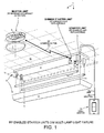
- Figure 1 is a simplified perspective diagram of a system 1 involving a master unit 2 and a fluorescent light fixture 3 involving replaceable RF-enabled starter units 4 and 5.
- Figure 2 is illustrative of one embodiment operable to dim a multi-lamp fluorescent light fixture by turning off all lamps and restarting a subset of lamps.
- Figure 3 is a perspective view of starter unit 4 of Figure 1 .
- Figure 4 is an exploded perspective view of the RF-enabled starter unit 4 of Figure 3 .
- Figure 5 is illustrative of one example of a method of identifying a wireless fluorescent lamp starter unit as a dimmer starter unit based on the electrical characteristics of the coupled ballast.
- Figure 6 is illustrative of a software indicator stored in memory as an indicator of dimmer status.
- Figure 7 is illustrative of a hardware pin configuration as an indicator of dimmer status.
- Figure 8 is illustrative of an RF communication including an indication of dimmer status.
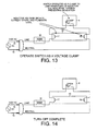
- FIGS 9-14 are circuit diagrams that illustrate how starter unit 4 can turn off fluorescent lamp 10 of the light fixture 3.
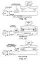
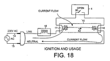
- FIG. 15-18 are circuit diagrams that illustrate how starter unit 4 can turn on fluorescent lamp 10 of the light fixture 3.
- FIG 19 is a flowchart that illustrates a first method 100 of dimming a multi-lamp fluorescent lamp fixture.
- a dimmer starter unit receives a DIM command and turns off a coupled lamp while other lamps remain illuminated. Optionally, all lamps are turned off and lamps not coupled to a dimmer starter are quickly restarted.
- FIG 1 is a diagram of a system 1.
- System 1 involves a master unit 2 and a plurality of multi-lamp fluorescent light fixtures having fluorescent lamp starter units.
- multi-lamp fluorescent light fixture 3 is pictured in Figure 1 .
- Other multi-lamp fluorescent light fixtures of system 1 are not pictured.
- Multi-lamp fluorescent light fixture 3 includes two fluorescent lamps 10 and 11 and starter units 4 and 5 associated with each lamp, respectively.
- master unit 2 is an infrared occupancy detector involving a Passive InfraRed (PIR) sensor 6 and a multi-section fresnel lens 7.
- PIR Passive InfraRed
- master unit 2 detects motion of infrared emitters in the field of view of the fresnel lens and detects the lack of motion of such infrared emitters. If the master unit detects motion, then the master unit is to turn on or to keep on the fluorescent lamps of the fluorescent light fixtures of system 1. If, on the other hand, the master unit does not detect motion, then the master unit is to dim the multi-lamp fixture 3 of system 1 to conserve electrical energy.
- master unit 2 includes an ambient light detector useable to indicate available ambient light. Based on the available ambient light, the master unit may dim the multi-lamp fixture 3 of system 1 to conserve electrical energy.
- multi-lamp light fixture 3 includes a base portion 8, a translucent cover portion 9, fluorescent bulbs or lamps 10 and 11, and their associated starter units 4 and 5, respectively. Ballasting inductances (not shown) are part of the base portion 8. Both the multi-lamp light fixture 3 and the master unit 2 are fixed to the ceiling 12 of a room in a building as shown.
- a wall switch 13 is connected by electrical wires 14 and 15 to all the light fixtures of system 1 in standard fashion so that a person in the room can manipulate the wall switch to turn on, and to turn off, the fluorescent lights.
- the electrical wires 14 and 15 are embedded in the walls and ceiling of the building. In the illustrated example, wire 14 is the LINE wire, whereas wire 15 is the NEUTRAL wire.
- Master unit 2 has a Radio-Frequency (RF) transceiver (transmitter and receiver) for engaging in RF communication, including RF communication 40 with the starter units of system 1.
- RF Radio-Frequency
- master unit 2 need not be connected to any hardwired electrical wiring in the building.
- the master unit 2 pictured is a self-contained, battery-powered, unit that is fixed to the ceiling 12 of the room illuminated by system 1. Master unit 2 can be easily fixed to ceiling 12 by application of adhesive tape or by a screw or other common attachment mechanism.
- Each multi-lamp light fixture of system 1 includes a plurality of replaceable starter units.
- Starter units 4 and 5 pictured in Figure 1 is one example. In this example, starter unit 4 is identified as a dimmer starter unit, and starter unit 5 is not identified as a dimmer starter unit. Dimmer starter units are distinguished by their response to a DIM command communicated via RF communication 40 from master unit 2.
- FIG. 2 is a more detailed view of system 1 illustrative of one example of dimming multi-lamp fixture 3.
- 230 Volts Alternating Current (AC) Mains voltage is the AC line voltage supplied to multi-lamp fluorescent light fixture 3.
- the AC line voltage is supplied over LINE conductor 14 through wall switch 13.
- a neutral voltage return path is provided by NEUTRAL conductor 15.
- Multi-lamp light fixture 3 can be electrically disconnected from the AC MAINS voltage supply by manipulation of wall switch 13.
- the AC line voltage is supplied to ballasts 16 and 19. Ballast 16 supplies current to fluorescent lamp 10 when lamp 10 is turned on.
- ballast 16 While turned on, current flows from ballast 16, through filament 17, over an electrical arc within lamp 10 to filament 18, and back to the AC MAINS voltage supply via NEUTRAL conductor 15.
- ballast 19 supplies current to fluorescent lamp 11 when lamp 11 is turned on. While turned on, current flows from ballast 19, through filament 20, over an electrical arc within lamp 11 to filament 21, and back to the AC MAINS voltage supply via NEUTRAL conductor 15.
- dimmer starter unit 4 receives a DIM command from master unit 2 via RF communication 40. In response, dimmer starter unit 4 begins to monitor the AC voltage being supplied to fluorescent lamp 10. When the AC voltage reaches voltage threshold level VTHRS1, dimmer starter unit 4 initiates turn off of lamp 10 at a time TOFF1. In another example, when dimmer starter unit 4 receives a DIM command from master unit 2, dimmer starter unit 4 immediately initiates turn off of lamp 10. After turn off of lamp 10 is complete, dimmer starter unit 4 does not restart lamp 10 in response to the DIM command.
- starter unit 5 receives the DIM command from master unit 2 via RF communication 40. In response, starter unit 5 begins to monitor the AC voltage being supplied to fluorescent lamp 11. When the AC voltage reaches voltage threshold level VTHRS2, starter unit 5 initiates turn off of lamp 11 at a time TOFF2. In another example, when starter unit 5 receives a DIM command from master unit 2, starter unit 5 immediately initiates turn off of lamp 11. After turn off of lamp 11 is complete, starter unit 5 waits for a period of time, and subsequently restarts lamp 11 in response to the DIM command. In yet another example starter unit 5 waits less than three seconds after turn off of lamp 11 before restarting lamp 11. Thus, after turn off of lamp 11 is complete, starter unit 5 restarts lamp 11 in response to the DIM command.
- dimmer starter unit 4 turns off lamp 10 in response to receiving the DIM command, while starter unit 5 receives, but does not respond to the DIM command, leaving lamp 11 illuminated. In yet another example, dimmer starter unit 4 turns off lamp 10 in response to receiving the DIM command, while starter unit 5 does not receive the DIM command and does not respond to the DIM command, leaving lamp 11 illuminated
- VTHRS1 and VTHRS2 are selected such that dimmer starter unit 4 initiates turn off of lamp 10 at substantially the same time as starter unit 5 initiates turn off of lamp 11.
- VTHRS1 and VTHRS2 may be selected to have different values or may be selected to have the same value. It is desireable to turn-off lamp 10 and lamp 11 at substantially the same time to reduce the probability that one lamp will restart the other due to electro-magnetic coupling effects.
- Ballast 16 has an inductive component that performs a current limiting function to stabilize current flow through lamp 10.
- ballast 19 also has an inductive component to stabilize current flow through lamp 11.
- ballast 19 also includes a capacitive component for purposes of power factor correction.
- ballast 19 may exhibit a capacitance of five microfarads.
- the difference in reactance between ballasts 16 and 19 causes an overall phase shift between the AC voltage supplied to fluorescent lamp 10 and the AC voltage supplied to fluorescent lamp 11.
- VTHRS1 and VTHRS2 are selected such that starter unit 4 initiates turn-off of lamp 10 at substantially the same time as starter unit 5 initiates turn-off of lamp 11.
- VTHRS1 and VTHRS2 are individually selected such that starter 4 initiates turn-off of lamp 10 within 1 millisecond of when starter unit 5 initiates turn-off of starter unit 5.
- the difference between TOFF1 and TOFF2 is less than one millisecond.
- VTHRS1 and VTHRS2 are selected to have the same value such that starter 4 initiates turn-off of lamp 10 within 1 millisecond of when starter unit 5 initiates turn-off of starter unit 5.
- the difference between TOFF1 and TOFF2 is less than one millisecond.
- Figure 3 is a perspective view of dimmer starter unit 4 and is typical of starter unit 5.
- FIG. 4 is an exploded perspective view of dimmer starter unit 4 and is typical of starter unit 5.
- Dimmer starter unit 4 includes a first terminal 34, a second terminal 35, a power supply 25, fluorescent lamp interface circuitry 26, a microcontroller integrated circuit 27, an RF transceiver 28, and an antenna 29.
- This circuitry is disposed on a printed circuit board (PCB) 30 as illustrated.
- PCB 30 is disposed within a cylindrical cap 31.
- Terminals 34 and 35 extend downward through holes in a circular disk-shaped base portion (not shown) of PCB material. The circular edge of this disk-shaped base portion joins with the circular bottom edge of cap 31 and forms a circular bottom of dimmer starter unit 4.
- Fluorescent lamp interface circuitry 26 includes a full wave rectifier that receives an AC voltage signal between terminals 34 and 35 and outputs full wave rectified signal between nodes 32 and 33.
- Power switch 36 is a switch that is used to turn on, and to turn off, fluorescent lamp 10.
- Power switch 36 is a power Field Effect Transistor (FET) that is controlled by microcontroller 27 via gate drive circuitry of circuitry 26.
- FET Field Effect Transistor
- Microcontroller 27 drives the gate of switch 36 and controls and monitors the remainder of interface circuitry 26 via signals communicated across conductors 37.
- ADC Analog-to-Digital Converter
- microcontroller 27 monitors and traces a voltage drop across a sense resistor 38. Thus, the resulting waveform between nodes 32 and 33 is indicative of the current flowing through switch 36 of starter unit 4.
- sense resistor 38 has a resistance value of approximately 0.1 ohms.
- Microcontroller 27 uses an on-board comparator and timer to detect and time zero-crossings of the AC signal on terminals 34 and 35. Microcontroller 27 determines when and how to control switch 36 based on the detected AC voltage between nodes 32 and 33, the time of the zero-crossings of the AC signal on terminals 34 and 35, and the magnitude of current flow through switch 36.
- microcontroller 27 during power up microcontroller 27 reads a known location in FLASH memory for voltage threshold information, including the magnitudes of VTHRS1 and VTHRS2. This voltage threshold information may be used by microcontroller 27 to initiate turn off of an associated fluorescent lamp in response to a DIM command.
- voltage threshold information may be used by microcontroller 27 to initiate turn off of an associated fluorescent lamp in response to a DIM command.
- microcontroller 27 reads a known location in FLASH memory for dimmer configuration information. This dimmer configuration information is used by microcontroller 27 to identify starter unit 4 as a dimmer starter unit.
- Power supply 25 receives the full wave rectified signal between nodes 32 and 33 and generates therefrom a direct current (DC) supply voltage VDD used to power microcontroller 27, RF transceiver 28, and interface circuitry 26.
- Power supply 25 includes a capacitance that is charged to the DC supply voltage VDD. This capacitance is large enough that it continues to power the microcontroller and RF transceiver of the starter unit for more than five seconds after 230 VAC power is removed from terminals 34 and 35.
- Microcontroller 27 communicates with and controls RF transceiver 28 via a bidirectional serial SPI bus and serial bus conductors 39.
- microcontroller 27 is a Z8F2480 8-bit microcontroller integrated circuit available from Zilog, Inc., 6800 Santa Maria Blvd., San Jose, California 95119.
- Microcontroller 27 includes an amount of non-volatile memory (FLASH memory) that can be written to and read from under software control during operation of dimmer starter unit 4.
- RF transceiver 28 is a SX1211 transceiver integrated circuit available from Semtech Corporation, 200 Flynn Road, Camarillo, California 93012.
- Transceiver 28 is coupled to antenna 29 via an impedance matching network (not shown) and a SAW filter (not shown).
- the SAW filter may, for example, be a B3716 SAW filter available from the Surface Acoustic Wave Components Division of EPCOS AG, P.O. Box 801709, 81617 Kunststoff, Germany.
- Antenna 29 may, for example, be a fifty ohm 0868AT43A0020 antenna available from Johanson Technology, Inc., 4001 Calle Tecate, Camarillo, CA 93012.
- the RF transceiver operates in a license free frequency band in the 863-878 MHz range (for example, about 868 MHz), in accordance with a reference design available from Semtech Corporation.
- the RF antenna and transceiver of dimmer starter unit 4 can receive an RF communication 40 (see Figure 1 ) from master unit 2.
- the data payload of the communication 40 is communicated across SPI bus conductors 39 to microcontroller 27 for processing.
- FIG. 5 is illustrative of one example by which a starter unit identifies itself as a dimmer starter unit.
- Multi-lamp light fixtures with multiple ballasts are typically constructed with an equal number of inductive ballasts versus inductive-capacitive ballasts for purposes of power factor correction.
- identifying starter units as dimmer starter units based on differing electrical characteristics of their associated ballasts is likely to result in half of the starters identifying themselves as dimmer starters and half not within a given multi-lamp light fixture.
- both ballasts 16 and 19 include an inductive component to stabilize current flow through lamps 10 and 11, respectively.
- ballast 19 also includes a capacitive component.
- ballasts 16 and 19 The difference in electrical characteristic between ballasts 16 and 19 causes a difference in peak amplitudes in the full wave rectified voltage sensed by starter unit 4 connected to ballast 16 and starter unit 5 connected to ballast 19, particularly when switch 36 is first closed. This indication is used by a starter unit to identify itself as a dimmer starter unit.
- the full wave rectified voltage VRECT monitored across nodes 32 and 33 is indicative of the AC current flow through switch 36 as discussed with respect to Figure 4 .
- the peaks of the full wave rectified voltage monitored by starter unit 4 vary over time between a minimum peak voltage signal, VMIN, and a maximum peak voltage signal, VMAX.
- Starter unit 4 calculates a difference between VMAX and VMIN, characterized as a difference voltage signal, VDIFF.
- starter unit 5 calculates a difference voltage signal, VDIFF associated with the full wave rectified voltage signal, VRECT, monitored by starter unit 5.
- Ballasts that include a larger capacitive component exhibit higher values of VDIFF than ballasts that are more purely inductive.
- the magnitude of VDIFF calculated by starter unit 4 is smaller than the magnitude of VDIFF calculated by starter unit 5.
- the magnitude of VDIFF is used to distinguish starter units as dimmer starters.
- starter unit 4 calculates VDIFF less than 0.2 volts, and thus identifies itself as a dimmer starter. Because starter unit 5 does not calculate VDIFF less than 0.2 volts, it does not identify itself as a dimmer starter. In another example, starter unit 4 calculates VDIFF less than 0.2 volts, and thus does not identify itself as a dimmer starter unit.
- starter unit 5 does not calculate VDIFF less than 0.2 volts and does identify itself as a dimmer starter.
- the value of 0.2 volts is only one example, any other value or combination of values may be used to make the determination of dimmer status.
- FIG. 6 is illustrative of another example by which a starter unit is identified as a dimmer starter unit based on a software indicator stored in memory.
- microcontroller 27 of starter unit 4 includes an amount of FLASH memory 44.
- Microcontroller 27 accesses an address in memory 44 where an amount of dimmer configuration information 43 is stored.
- dimmer configuration information could be a single bit stored in memory 44 and depending on the value of the stored bit, microcontroller 27 identifies starter 4 as a dimmer starter or not.
- dimmer configuration information 43 is written into memory 44 during manufacture or installation of starter unit 4. In other examples, information 43 is remotely programmed via a wireless communication received by starter unit 4.
- FIG. 7 is illustrative of another example by which a starter unit is identified as a dimmer starter unit based on a hardware indication.
- starter unit 4 includes a hardware register 45.
- the values stored in hardware register 45 are manually selected by configuring a pin or switch associated with each bit.
- dimmer configuration information 43 is a single bit configured in hardware register 45.
- Hardware register 45 is communicatively linked to microcontroller 27 by conductors 46. Based on the pin configuration of hardware register 45, microcontroller 27 accesses dimmer configuration information 43, and depending on the value of the manually configured hardware bit, microcontroller 27 identifies starter 4 as a dimmer starter or not.
- dimmer configuration information 43 is stored as multiple bits configured in hardware register 45. In this example a plurality of dimmer starters can be distinguished as dimmer starters of different groups.
- starter units can be identified as dimmer starter units based on an R/F communication 40 from master unit 2.
- system 1 is configured such that each RF communication includes a command that includes both a source registration identifier code identifying master unit 2 as well as a destination registration identifier code identifying the starter unit or a group of starter units.
- the starter units are individually and group controllable.
- a starter unit receives an RF communication, and before carrying out the command of the received RF communication, the starter unit uses registration information stored in its FLASH memory to confirm that the RF communication received is intended for that starter unit.
- starter unit 4 receives a RF communication 40 that includes a source registration identifier code identifying master unit 2 as well as a destination registration identifier code.
- Starter unit 4 accesses registration information 47 stored in its FLASH memory 44 to confirm that the RF communication received is intended for starter unit 4.
- the RF communication includes a command to starter unit 4 indicating that starter unit 4 should identify itself as a dimmer starter unit.
- Starter unit 4 responds to this command by operating as a dimmer starter unit.
- starter unit 4 may write a register in FLASH memory to a particular value to indicate that starter unit 4 is a dimmer starter unit.
- starter unit 5 of Figure 2 receives the RF communication 40 that includes a source registration identifier code identifying master unit 2 as well as a destination registration identifier code.
- Starter unit 5 accesses registration information 47 stored in its FLASH memory 44.
- registration information 47 of starter unit 5 will not match up with the destination registration identifier code and starter unit 5 will not respond to RF communication 40.
- starter unit 5 will not identify itself as a dimmer starter unit and will not operate as a dimmer starter unit.
- some starter units of multi-lamp fixture 3 are configured as dimmer starter units and others are not.
- FIGS 9-14 illustrate how dimmer starter unit 4 can turn off fluorescent lamp 10.
- starter unit 5 can turn off fluorescent lamp 11.
- starter units 4 and 5 can dim multi-lamp fixture 3 as illustrated in Figure 2 .
- fluorescent lamp 10 is on and the circuit is in the turned on state illustrated in Figure 9 .
- An AC current flows in current path 41 through LINE conductor 14, through ballast 16, through filament 17, through an arc formed through lamp 10, through filament 18, and to AC NEUTRAL conductor 15.
- the continuous AC current flow continues to keep the filaments hot such that the arc is maintained, the current flow continues, and the lamp remains in the turned on or ignited state.
- switch 36 remains open.
- starter 4 receives a wireless communication 40 that includes a DIM command.
- wireless communication 40 is transmitted by master unit 2 (see Figure 1 ).
- starter unit 4 begins to monitor the full wave rectified voltage signal, VRECT, present between nodes 32 and 33.
- Microcontroller 27 monitors and traces the AC voltage waveform between nodes 32 and 33 using an Analog-to-Digital Converter (ADC) that is part of the microcontroller.
- ADC Analog-to-Digital Converter
- starter unit 4 initiates turn off of fluorescent lamp 10 when VRECT reaches a pre-programmed voltage threshold, VTHRS1. In the illustrated example, VRECT reaches VTHRS1 at a time TOFF1.
- Microcontroller 27 detects that the monitored signal, VRECT, has reached VTHRS1 and in response, controls switch 36 to close.
- dimmer starter unit 4 immediately controls switch 36 to close in response to receiving the DIM command.
- switch 36 closes the current flow stops flowing through lamp 10 but rather flows through closed switch 36.
- the electric arc within lamp 10 is stopped and fluorescent lamp 10 is turned off or extinguished.
- Current, however, continues to flow through filaments 17 and 18 and the filaments continue to be heated.
- Switch 36 can only remain closed in this condition for a short amount of time or the switch will become overheated and will be destroyed.
- switch 36 is opened as illustrated in Figure 12 .
- ballast 16 causes a voltage to start to develop across ballast 16, but before the voltage can increase to the point that an arc is ignited through lamp 10, switch 36 is made to operate as a voltage clamp to limit the magnitude of the voltage spike.
- Clamp operation of switch 36 is illustrated in Figure 13 by showing switch 36 in dashed lines. Due to the clamping action of switch 36, the voltage across ballast 16 is not high enough to ignite an arc through lamp 10, and energy stored in a magnetic field in ballast 16 is dissipated. After enough of the energy stored in ballast 16 has been dissipated and after filaments 17 and 18 have stopped ionizing gas to an adequate degree, then switch 36 is opened on a constant basis without igniting an arc. This condition is illustrated in Figure 14 . There is no current flow, and the filaments 17 and 18 begin to cool.
- FIGs 15-18 illustrate how dimmer starter unit 4 can turn on fluorescent lamp 10.
- starter unit 5 can turn on fluorescent lamp 11.
- switch 36 of dimmer starter unit 4 is open, and no current is flowing through filaments 17 and 18.
- the filaments 17 and 18 are relatively cold.
- Microcontroller 27 controls switch 36 to close as shown in Figure 16 .
- An AC current then flows in current path 41 through LINE conductor 14, through ballast 16, through filament 17, through closed switch 36, through filament 18, and to AC NEUTRAL conductor 15.
- This AC current flow 41 causes filaments 17 and 18 to heat, and causes gas in lamp 10 to ionize.
- This current flow through switch 36 can only be sustained for a relatively short amount of time or switch 36 will overheat and be destroyed.
- switch 36 is opened as illustrated in Figure 17 .
- the current flow through ballast 16 is interrupted, and this causes a large voltage (for example, one thousand volts or more) to develop across ballast 16.
- a large voltage V+ is present between the two filaments 17 and 18.
- large voltage V+ ignites the lamp by causing an arc 42 to form through lamp 10. Due to arc 42, the resistance between the filaments through the lamp decreases. The continued AC current flow continues to keep the filaments hot such that the arc is maintained and current flow continues.
- the fluorescent lamp is then on and switch 36 remains open.
- Figure 19 illustrates one example of a method 100 of dimming a multi-lamp fluorescent fixture.
- master unit 2 transmits a communication that includes a dim command (step 101).
- starter unit 4 and starter unit 5 receive this communication (steps 102 and 104, respectively).
- the communication is an RF communication from master unit 2 that is received by starter units 4 and 5.
- the communication is transmitted from master unit 2 to starter units 4 and 5 by way of wired conductors.
- starter unit 4 initiates turn-off of fluorescent lamp 10 (step 103) while fluorescent lamp 11 of multi-lamp fixture 3 remains illuminated.
- starter unit 5 in response to receiving the communication, starter unit 5 initiates turn-off of fluorescent lamp 11 (step 105), such that both lamp 10 and 11 are turned off at substantially the same time. In the present example, the time elapsed between the turn off of lamp 10 and lamp 11 is less than one millisecond. After turn off of lamp 11, starter unit 5 initiates turn on of lamp 11 (step 106). In the present example, starter unit 5 initiates turn on of lamp 11 within three seconds of turning off lamp 11. In this manner, multi-lamp fixture 3 is dimmed by turning off a subset of fluorescent lamps within the fixture.
- the teachings of this patent document have general applicability and are not limited to the specific embodiments described above.
- the particular ways of dimming a multi-lamp fluorescent light fixture by turning off a subset of fluorescent lamps using wireless fluorescent lamp starter units as set forth in the description above are just illustrative examples.
- Other ways of identifying a starter unit as a dimmer starter unit in the field are possible.
- the master unit may communicate on an ad hoc basis to identify individual starter units as dimmer starter units.
- the master unit may not detect occupancy, but rather detect ambient light.
- the master unit may detect ambient light levels and selectively turn off fluorescent lamps to implement daylight harvesting in building environments where ambient light may be available to at least partially illuminate the space.
- a master unit may dim some multi-lamp fluorescent light fixtures separately from others.
- the RF transceivers of the starter units may form a wireless network usable to communicate other types of information.
- Master units need not be installed on ceilings and need not take the form illustrated in Figure 1 , but rather may take other forms and may be incorporated into other objects such as wall switches.
- the dimming of multi-lamp fluorescent light fixtures using wirelessly-controllable starter units is not limited to any particular type of fluorescent lamp technology and is not limited to preheat lamps having thermionic filaments and inductive ballasts.
- the master/starter unit system can work with other AC power sources such as 120 volts as well as with DC power sources. Accordingly, various modifications, adaptations, and combinations of various features of the described embodiments can be practiced without departing from the scope of the invention as set forth in the claims.
Abstract
Description
- The described embodiments relate to starter units for fluorescent lamps.
- A multi-lamp fluorescent light fixture involves a number of tubular fluorescent bulbs. Each fluorescent bulb is also referred to here as a fluorescent lamp. Each tube is a glass tube that contains an ionizable gas and a small portion of mercury. There are filaments at each end of the tube. By application of proper electrical voltages, the filaments can be made to heat up and to ionize the ionizable gas in the tube. After sufficient heating, if a voltage of adequate magnitude is subsequently provided between the filaments, an electrical arc can be initiated through the ionized gas in the tube between the filaments. The arc involves a flow of current from one filament, through the ionized gas, to the other filament. Energetic electrons in this current flow collide with the mercury atoms, thereby exciting the mercury atoms and causing them to emit ultraviolet radiation. The emitted ultraviolet radiation is absorbed by and excites a phosphor coating on the inside of the walls of the tube. The phosphor coating fluoresces and emits radiation in the visible spectrum (i.e., visible light). The visible light passes outward through the glass and is usable for illuminating purposes.
- Some such multi-lamp fluorescent light fixtures involve a plurality of starter circuits, each commonly referred to as a "starter." In a first step, a switch in the starter closes and forms an electrical connection between the filament at one end of a tube and the filament at the other end of the tube such that an AC current can flow from an AC power source, through an ballast, through one filament, through the closed switch of the starter, and through the second filament, and back to the AC power source. This AC current flow causes the filaments to heat. The heating of the filaments causes gas surrounding the filaments to ionize. Once the gas is ionized in this way, then the switch in the starter is opened. The opening of the switch cuts current flow through the ballast, thereby causing a large voltage spike to develop across the ballast. Due to the circuit topology, this large voltage is present between the two filaments. The voltage is large enough to strike an arc through the gas. Once the arc is established, the resistance between the two filaments through the gas decreases. This allows the current to continue to flow through the gas without a large voltage being present between the filaments. The switch is left open, the current continues to flow, filaments continue to be heated, the arc is maintained, and the current flow is regulated by the ballast. The fluorescent lamp is then on and emits visible light to illuminate an area.
- In multi-lamp fluorescent light fixtures, the starters may fail. Each starter is therefore sometimes made to be a replaceable unit. Great numbers of fluorescent light fixtures with replaceable starter units are installed throughout the world. Large numbers of such fluorescent light fixtures are installed in public buildings, office buildings, and other large buildings. Quite often the fluorescent lights are left on and consume electrical energy even though the area served does not need to be illuminated. A way of preventing this waste of electrical energy is desired.
- Infrared motion detecting wall switches are often employed to prevent the waste of energy due to lights being left on when lighting is not needed. If an infrared motion detector in the wall switch does not detect motion of an infrared emitter (for example, a human body) in the vicinity of the wall switch, then circuitry in the wall switch determines that the room is not occupied by a person. Presumably if a person were in the room, the person would be moving to some extent and would be detected as a moving infrared emitter. If the wall switch determines that the room is unoccupied because it does not detect any such moving infrared emitter, then the wall switch turns off the fluorescent lights on the circuit controlled by the wall switch. The wall switch turns off the fluorescent lights by cutting AC power flowing to the fluorescent lamp light fixtures through power lines hardwired into the building. If, however, the wall switch detects a moving infrared emitter, then the wall switch turns on the lights by energizing the hardwired power lines so that AC power is supplied to the fluorescent light fixtures through the hardwired power lines.
- The wall switch motion detection system involving hardwired power lines embedded in the walls and ceilings of buildings is quite popular, but a wireless system has been proposed whereby each of the replaceable starter units is to be provided with an RF receiver. Each starter unit is able to selectively turn off a fluorescent lamp within a multi-lamp fluorescent light fixture to dim the light output of the fixture in response to RF commands received from a master control unit.
- A multi-lamp fluorescent light fixture includes a plurality of replaceable fluorescent lamp starter units. Each starter unit has a built-in microcontroller, an RF (Radio-Frequency) receiver, and communicates wirelessly with a master unit. Each starter unit can be wirelessly controlled to dim the multi-lamp fixture. Each starter unit receives a DIM command. Each starter unit identified as a dimmer starter unit responds to the DIM command by turning off coupled fluorescent lamps. In one example, starter units not identified as dimmer starter units respond by leaving coupled lamps turned on. In another example, starter units not identified as dimmer starter units respond by turning off and quickly restarting coupled lamps.
- In one aspect, a starter unit of a multi-lamp light fixture identifies itself as a dimmer starter unit by monitoring the Alternating Current (AC) voltage supplied to coupled fluorescent lamps, identifying an electrical characteristic of the AC voltage, and identifying itself as a dimmer starter unit based on the electrical characteristic. In one example, the peaks of the AC voltage vary over time between a minimum peak voltage signal, VMIN, and a maximum peak voltage signal, VMAX. The voltage difference value, VDIFF, between VMAX and VMIN is used to indicate whether a starter unit should identify itself as a dimmer starter unit.
- In another aspect, a starter unit of a multi-lamp light fixture identifies itself as a dimmer starter unit by reading dimmer configuration information stored in on-board memory. In one example, dimmer configuration information is programmed into memory as part of the manufacturing or installation process. In another example, dimmer configuration information is wirelessly communicated from a master unit to the starter unit and the starter unit stores this information in on-board memory.
- In another aspect, a starter unit of a multi-lamp light fixture identifies itself as a dimmer starter unit based on a hardware indicator. In one example, a pin is configured on-board the starter unit and the pin configuration indicates whether the starter unit is designated as a dimmer starter unit.
- Systems of existing light fixtures are retrofitted with such wireless starter units without requiring a person to touch the AC power mains, and thereby are made controllable by a master unit so that the master unit can dim the lights if room occupancy is not detected or if sufficient ambient light is available. The master unit can be installed in a location to detect whether an area illuminated by the fluorescent light fixture is occupied by a person or is sufficiently illuminated by ambient light. The master unit may, for example, be a battery-powered unit that is fixed to the ceiling of a room.
In the following, preferred aspects of the present invention advantageous alternatives are summarized.
According to the present invention, a method of dimming a multi-lamp fluorescent light fixture comprises (a) turning off a first fluorescent lamp using a first wireless fluorescent lamp starter unit, wherein the first fluorescent lamp is taken from a plurality of illuminated fluorescent lamps of the multi-lamp fluorescent light fixture.
According to a preferred aspect of the present invention, the method comprises (b) turning off a second fluorescent lamp of the plurality of illuminated flouorescent lamps using a second wireless fluorescent lamp starter unit at substantially the same time as the turning off of (a), and (c) turning on the second fluorescent lamp using the second wireless starter unit after the turning off of (b) while the first fluorescent lamp remains turned off.
Advantageously, an alternating current (AC) line voltage supply supplies electrical power to the first fluorescent lamp and the second fluorescent lamp, wherein the dimming of the multi-lamp fluorescent light fixture is performed without disconnecting the AC line voltage supply.
Advantageously, the method comprises (b) dimming the multi-lamp fluorescent light fixture in response to receiving a wireless communication from a master unit.
Advantageously, the time between the turning off of the first lamp and the turning off of the second lamp is less than one millisecond.
According to a further preferred aspect of the present invention, the time between the turning off of the second lamp and the subsequent turning on of the second lamp is less than three seconds.
According to a further preferred aspect of the present invention, the method further comprises (b) identifying the first starter unit as a dimmer starter.
According to a further preferred aspect of the present invention, the identifying of (b) involves (b1) monitoring an AC voltage indicative of an AC current flowing through the first starter unit, (b2) identifying an electrical characteristic of the first AC voltage based on the monitoring of (b1), and (b3) identifying the first starter unit as a dimmer starter based on the identifying of (b2).
According to a further preferred aspect of the present invention, the monitoring of (b1) and the identifying of (b2) and (b3) are performed by the first starter unit.
According to a further preferred aspect of the present invention, the identifying of (b) involves (b1) accessing dimmer configuration information stored in an amount of on-board memory, wherein said dimmer configuration information identifies the first starter unit as a dimmer starter.
According to a further preferred aspect of the present invention, the identifying of (b) involves (b1) accessing dimmer configuration information stored in a hardware register, wherein said dimmer configuration information identifies the first starter unit as a dimmer starter.
According to a further preferred aspect of the present invention, the identifying of (b) involves (b1) receiving a Radio Frequency (RF) communication from a master unit that identifies the first starter unit as a dimmer starter.
According to the present invention, an apparatus comprises a first wireless fluorescent lamp starter unit adapted to receive a wireless communication, a first fluorescent lamp coupled to the first starter unit, a second wireless fluorescent lamp starter unit adapted to receive the wireless communication, and a second fluorescent lamp coupled to the second starter unit, wherein the second starter responds to the wireless communication by turning off the second lamp and subsequently turning on the second lamp, and wherein the first starter responds to the wireless communication by turning off the first lamp and not subsequently turning on the first lamp.
Advantageously, the wireless communication is a dim command received from a master unit.
According to a preferred aspect of the present invention, the time between turning off the second lamp and subsequently turning on the second lamp is less than three seconds.
Advantageously, the time between turning off of the first lamp and turning off of the second lamp is less than one millisecond.
According to a further preferred aspect of the present invention, the apparatus comprises a ballast coupled to the first starter unit, wherein the first starter unit identifies itself as a dimmer starter by monitoring an indication of an Alternating Current (AC) current supplied to the starter unit from the ballast.
According to a further preferred aspect of the present invention, the first starter unit identifies itself as a dimmer starter by receiving a second wireless communication from a master unit.
According to the present invention, an apparatus comprises a first fluorescent lamp coupled to a first ballast, wherein the first ballast is adapted to receive an Alternating Current (AC) line voltage from an AC line voltage supply, a second fluorescent lamp coupled to a second ballast, wherein the second ballast is adapted to receive the AC line voltage from an AC line voltage supply, and means for turning off the first lamp and the second lamp at substantially the same time without disconnecting the AC line voltage supply, and subsequently turning on the second lamp without turning on the first lamp.
According to a preferred aspect of the present invention, the means turns off the second lamp and subsequently turns on the second lamp within one millisecond. - Further details and embodiments and techniques are described in the detailed description below. This summary does not purport to define the invention. The invention is defined by the claims.
- The accompanying drawings, where like numerals indicate like components, illustrate embodiments of the invention.
-
Figure 1 is a simplified perspective diagram of asystem 1 involving amaster unit 2 and a fluorescentlight fixture 3 involving replaceable RF-enabledstarter units -
Figure 2 is illustrative of one embodiment operable to dim a multi-lamp fluorescent light fixture by turning off all lamps and restarting a subset of lamps. -
Figure 3 is a perspective view ofstarter unit 4 ofFigure 1 . -
Figure 4 is an exploded perspective view of the RF-enabledstarter unit 4 ofFigure 3 . -
Figure 5 is illustrative of one example of a method of identifying a wireless fluorescent lamp starter unit as a dimmer starter unit based on the electrical characteristics of the coupled ballast. -
Figure 6 is illustrative of a software indicator stored in memory as an indicator of dimmer status. -
Figure 7 is illustrative of a hardware pin configuration as an indicator of dimmer status. -
Figure 8 is illustrative of an RF communication including an indication of dimmer status. -
Figures 9-14 are circuit diagrams that illustrate howstarter unit 4 can turn offfluorescent lamp 10 of thelight fixture 3. -
Figure 15-18 are circuit diagrams that illustrate howstarter unit 4 can turn onfluorescent lamp 10 of thelight fixture 3. -
Figure 19 is a flowchart that illustrates afirst method 100 of dimming a multi-lamp fluorescent lamp fixture. A dimmer starter unit receives a DIM command and turns off a coupled lamp while other lamps remain illuminated. Optionally, all lamps are turned off and lamps not coupled to a dimmer starter are quickly restarted. - Reference will now be made in detail to some embodiments of the invention, examples of which are illustrated in the accompanying drawings.
-
Figure 1 is a diagram of asystem 1.System 1 involves amaster unit 2 and a plurality of multi-lamp fluorescent light fixtures having fluorescent lamp starter units. For illustrative purposes, one multi-lampfluorescent light fixture 3 is pictured inFigure 1 . Other multi-lamp fluorescent light fixtures ofsystem 1 are not pictured. Multi-lamp fluorescentlight fixture 3 includes twofluorescent lamps starter units master unit 2 is an infrared occupancy detector involving a Passive InfraRed (PIR) sensor 6 and amulti-section fresnel lens 7. Using techniques well known in the art,master unit 2 detects motion of infrared emitters in the field of view of the fresnel lens and detects the lack of motion of such infrared emitters. If the master unit detects motion, then the master unit is to turn on or to keep on the fluorescent lamps of the fluorescent light fixtures ofsystem 1. If, on the other hand, the master unit does not detect motion, then the master unit is to dim themulti-lamp fixture 3 ofsystem 1 to conserve electrical energy. In another example,master unit 2 includes an ambient light detector useable to indicate available ambient light. Based on the available ambient light, the master unit may dim themulti-lamp fixture 3 ofsystem 1 to conserve electrical energy. - In the illustration of
Figure 1 , multi-lamplight fixture 3 includes abase portion 8, atranslucent cover portion 9, fluorescent bulbs orlamps starter units base portion 8. Both the multi-lamplight fixture 3 and themaster unit 2 are fixed to theceiling 12 of a room in a building as shown. Awall switch 13 is connected byelectrical wires system 1 in standard fashion so that a person in the room can manipulate the wall switch to turn on, and to turn off, the fluorescent lights. Theelectrical wires wire 14 is the LINE wire, whereaswire 15 is the NEUTRAL wire. -
Master unit 2 has a Radio-Frequency (RF) transceiver (transmitter and receiver) for engaging in RF communication, includingRF communication 40 with the starter units ofsystem 1. As pictured,master unit 2 need not be connected to any hardwired electrical wiring in the building. Themaster unit 2 pictured is a self-contained, battery-powered, unit that is fixed to theceiling 12 of the room illuminated bysystem 1.Master unit 2 can be easily fixed toceiling 12 by application of adhesive tape or by a screw or other common attachment mechanism. Each multi-lamp light fixture ofsystem 1 includes a plurality of replaceable starter units.Starter units Figure 1 is one example. In this example,starter unit 4 is identified as a dimmer starter unit, andstarter unit 5 is not identified as a dimmer starter unit. Dimmer starter units are distinguished by their response to a DIM command communicated viaRF communication 40 frommaster unit 2. -
Figure 2 is a more detailed view ofsystem 1 illustrative of one example of dimmingmulti-lamp fixture 3. In this example, 230 Volts Alternating Current (AC) Mains voltage is the AC line voltage supplied to multi-lamp fluorescentlight fixture 3. The AC line voltage is supplied overLINE conductor 14 throughwall switch 13. A neutral voltage return path is provided byNEUTRAL conductor 15. Multi-lamplight fixture 3 can be electrically disconnected from the AC MAINS voltage supply by manipulation ofwall switch 13. Within multi-lamplight fixture 3, the AC line voltage is supplied to ballasts 16 and 19.Ballast 16 supplies current tofluorescent lamp 10 whenlamp 10 is turned on. While turned on, current flows fromballast 16, throughfilament 17, over an electrical arc withinlamp 10 tofilament 18, and back to the AC MAINS voltage supply viaNEUTRAL conductor 15. Similarly,ballast 19 supplies current tofluorescent lamp 11 whenlamp 11 is turned on. While turned on, current flows fromballast 19, throughfilament 20, over an electrical arc withinlamp 11 tofilament 21, and back to the AC MAINS voltage supply viaNEUTRAL conductor 15. - In one example,
dimmer starter unit 4 receives a DIM command frommaster unit 2 viaRF communication 40. In response,dimmer starter unit 4 begins to monitor the AC voltage being supplied tofluorescent lamp 10. When the AC voltage reaches voltage threshold level VTHRS1,dimmer starter unit 4 initiates turn off oflamp 10 at a time TOFF1. In another example, whendimmer starter unit 4 receives a DIM command frommaster unit 2,dimmer starter unit 4 immediately initiates turn off oflamp 10. After turn off oflamp 10 is complete,dimmer starter unit 4 does not restartlamp 10 in response to the DIM command. - In the illustrated example,
starter unit 5 receives the DIM command frommaster unit 2 viaRF communication 40. In response,starter unit 5 begins to monitor the AC voltage being supplied tofluorescent lamp 11. When the AC voltage reaches voltage threshold level VTHRS2,starter unit 5 initiates turn off oflamp 11 at a time TOFF2. In another example, whenstarter unit 5 receives a DIM command frommaster unit 2,starter unit 5 immediately initiates turn off oflamp 11. After turn off oflamp 11 is complete,starter unit 5 waits for a period of time, and subsequently restartslamp 11 in response to the DIM command. In yet anotherexample starter unit 5 waits less than three seconds after turn off oflamp 11 before restartinglamp 11. Thus, after turn off oflamp 11 is complete,starter unit 5 restartslamp 11 in response to the DIM command. - In another example,
dimmer starter unit 4 turns offlamp 10 in response to receiving the DIM command, whilestarter unit 5 receives, but does not respond to the DIM command, leavinglamp 11 illuminated. In yet another example,dimmer starter unit 4 turns offlamp 10 in response to receiving the DIM command, whilestarter unit 5 does not receive the DIM command and does not respond to the DIM command, leavinglamp 11 illuminated - As illustrated in
Figure 2 , VTHRS1 and VTHRS2 are selected such thatdimmer starter unit 4 initiates turn off oflamp 10 at substantially the same time asstarter unit 5 initiates turn off oflamp 11. VTHRS1 and VTHRS2 may be selected to have different values or may be selected to have the same value. It is desireable to turn-offlamp 10 andlamp 11 at substantially the same time to reduce the probability that one lamp will restart the other due to electro-magnetic coupling effects.Ballast 16 has an inductive component that performs a current limiting function to stabilize current flow throughlamp 10. Similarly,ballast 19 also has an inductive component to stabilize current flow throughlamp 11. In addition, however,ballast 19 also includes a capacitive component for purposes of power factor correction. For example,ballast 19 may exhibit a capacitance of five microfarads. The difference in reactance betweenballasts fluorescent lamp 10 and the AC voltage supplied tofluorescent lamp 11. Based on this phase shift, VTHRS1 and VTHRS2 are selected such thatstarter unit 4 initiates turn-off oflamp 10 at substantially the same time asstarter unit 5 initiates turn-off oflamp 11. In one example, VTHRS1 and VTHRS2 are individually selected such thatstarter 4 initiates turn-off oflamp 10 within 1 millisecond of whenstarter unit 5 initiates turn-off ofstarter unit 5. Thus the difference between TOFF1 and TOFF2 is less than one millisecond. In another example, VTHRS1 and VTHRS2 are selected to have the same value such thatstarter 4 initiates turn-off oflamp 10 within 1 millisecond of whenstarter unit 5 initiates turn-off ofstarter unit 5. Thus the difference between TOFF1 and TOFF2 is less than one millisecond. -
Figure 3 is a perspective view ofdimmer starter unit 4 and is typical ofstarter unit 5. -
Figure 4 is an exploded perspective view ofdimmer starter unit 4 and is typical ofstarter unit 5.Dimmer starter unit 4 includes afirst terminal 34, asecond terminal 35, apower supply 25, fluorescentlamp interface circuitry 26, a microcontroller integratedcircuit 27, anRF transceiver 28, and anantenna 29. This circuitry is disposed on a printed circuit board (PCB) 30 as illustrated.PCB 30 is disposed within acylindrical cap 31.Terminals cap 31 and forms a circular bottom ofdimmer starter unit 4. - Fluorescent
lamp interface circuitry 26 includes a full wave rectifier that receives an AC voltage signal betweenterminals nodes Power switch 36 is a switch that is used to turn on, and to turn off,fluorescent lamp 10.Power switch 36 is a power Field Effect Transistor (FET) that is controlled bymicrocontroller 27 via gate drive circuitry ofcircuitry 26.Microcontroller 27 drives the gate ofswitch 36 and controls and monitors the remainder ofinterface circuitry 26 via signals communicated across conductors 37. Whenswitch 36 is open,microcontroller 27 monitors and traces the AC voltage waveform betweennodes switch 36 is closed,microcontroller 27 monitors and traces a voltage drop across asense resistor 38. Thus, the resulting waveform betweennodes switch 36 ofstarter unit 4.
In one example,sense resistor 38 has a resistance value of approximately 0.1 ohms.Microcontroller 27 uses an on-board comparator and timer to detect and time zero-crossings of the AC signal onterminals Microcontroller 27 determines when and how to controlswitch 36 based on the detected AC voltage betweennodes terminals switch 36. In one example, during power upmicrocontroller 27 reads a known location in FLASH memory for voltage threshold information, including the magnitudes of VTHRS1 and VTHRS2. This voltage threshold information may be used bymicrocontroller 27 to initiate turn off of an associated fluorescent lamp in response to a DIM command. In another example, during power upmicrocontroller 27 reads a known location in FLASH memory for dimmer configuration information. This dimmer configuration information is used bymicrocontroller 27 to identifystarter unit 4 as a dimmer starter unit. -
Power supply 25 receives the full wave rectified signal betweennodes power microcontroller 27,RF transceiver 28, andinterface circuitry 26.Power supply 25 includes a capacitance that is charged to the DC supply voltage VDD. This capacitance is large enough that it continues to power the microcontroller and RF transceiver of the starter unit for more than five seconds after 230 VAC power is removed fromterminals -
Microcontroller 27 communicates with and controlsRF transceiver 28 via a bidirectional serial SPI bus andserial bus conductors 39. In one embodiment,microcontroller 27 is a Z8F2480 8-bit microcontroller integrated circuit available from Zilog, Inc., 6800 Santa Teresa Blvd., San Jose, California 95119.Microcontroller 27 includes an amount of non-volatile memory (FLASH memory) that can be written to and read from under software control during operation ofdimmer starter unit 4. In one embodiment,RF transceiver 28 is a SX1211 transceiver integrated circuit available from Semtech Corporation, 200 Flynn Road, Camarillo, California 93012.Transceiver 28 is coupled toantenna 29 via an impedance matching network (not shown) and a SAW filter (not shown). The SAW filter may, for example, be a B3716 SAW filter available from the Surface Acoustic Wave Components Division of EPCOS AG, P.O. Box 801709, 81617 Munich, Germany.Antenna 29 may, for example, be a fifty ohm 0868AT43A0020 antenna available from Johanson Technology, Inc., 4001 Calle Tecate, Camarillo, CA 93012. The RF transceiver operates in a license free frequency band in the 863-878 MHz range (for example, about 868 MHz), in accordance with a reference design available from Semtech Corporation. The RF antenna and transceiver ofdimmer starter unit 4 can receive an RF communication 40 (seeFigure 1 ) frommaster unit 2. The data payload of thecommunication 40 is communicated acrossSPI bus conductors 39 tomicrocontroller 27 for processing. -
Figure 5 is illustrative of one example by which a starter unit identifies itself as a dimmer starter unit. Multi-lamp light fixtures with multiple ballasts are typically constructed with an equal number of inductive ballasts versus inductive-capacitive ballasts for purposes of power factor correction. Thus, identifying starter units as dimmer starter units based on differing electrical characteristics of their associated ballasts is likely to result in half of the starters identifying themselves as dimmer starters and half not within a given multi-lamp light fixture. In this example, bothballasts lamps ballast 19 also includes a capacitive component. The difference in electrical characteristic betweenballasts starter unit 4 connected toballast 16 andstarter unit 5 connected toballast 19, particularly whenswitch 36 is first closed. This indication is used by a starter unit to identify itself as a dimmer starter unit. - By way of example, current flows through
sense resistor 38 whenswitch 36 ofstarter unit 4 is first closed. Thus, the full wave rectified voltage VRECT monitored acrossnodes switch 36 as discussed with respect toFigure 4 . The peaks of the full wave rectified voltage monitored bystarter unit 4 vary over time between a minimum peak voltage signal, VMIN, and a maximum peak voltage signal, VMAX.Starter unit 4 calculates a difference between VMAX and VMIN, characterized as a difference voltage signal, VDIFF. Analogously,starter unit 5 calculates a difference voltage signal, VDIFF associated with the full wave rectified voltage signal, VRECT, monitored bystarter unit 5. Ballasts that include a larger capacitive component exhibit higher values of VDIFF than ballasts that are more purely inductive. Thus, the magnitude of VDIFF calculated bystarter unit 4 is smaller than the magnitude of VDIFF calculated bystarter unit 5. The magnitude of VDIFF is used to distinguish starter units as dimmer starters. In one example,starter unit 4 calculates VDIFF less than 0.2 volts, and thus identifies itself as a dimmer starter. Becausestarter unit 5 does not calculate VDIFF less than 0.2 volts, it does not identify itself as a dimmer starter. In another example,starter unit 4 calculates VDIFF less than 0.2 volts, and thus does not identify itself as a dimmer starter unit. Whereasstarter unit 5 does not calculate VDIFF less than 0.2 volts and does identify itself as a dimmer starter. The value of 0.2 volts is only one example, any other value or combination of values may be used to make the determination of dimmer status. -
Figure 6 is illustrative of another example by which a starter unit is identified as a dimmer starter unit based on a software indicator stored in memory. In the present example,microcontroller 27 ofstarter unit 4 includes an amount ofFLASH memory 44.Microcontroller 27 accesses an address inmemory 44 where an amount ofdimmer configuration information 43 is stored. For example, dimmer configuration information could be a single bit stored inmemory 44 and depending on the value of the stored bit,microcontroller 27 identifiesstarter 4 as a dimmer starter or not. In the present example,dimmer configuration information 43 is written intomemory 44 during manufacture or installation ofstarter unit 4. In other examples,information 43 is remotely programmed via a wireless communication received bystarter unit 4. -
Figure 7 is illustrative of another example by which a starter unit is identified as a dimmer starter unit based on a hardware indication. In the present example,starter unit 4 includes a hardware register 45. The values stored in hardware register 45 are manually selected by configuring a pin or switch associated with each bit. In one example,dimmer configuration information 43 is a single bit configured in hardware register 45. Hardware register 45 is communicatively linked tomicrocontroller 27 by conductors 46. Based on the pin configuration of hardware register 45,microcontroller 27 accessesdimmer configuration information 43, and depending on the value of the manually configured hardware bit,microcontroller 27 identifiesstarter 4 as a dimmer starter or not. In another example,dimmer configuration information 43 is stored as multiple bits configured in hardware register 45. In this example a plurality of dimmer starters can be distinguished as dimmer starters of different groups. - As illustrated in
Figure 8 , starter units can be identified as dimmer starter units based on an R/F communication 40 frommaster unit 2. For example,system 1 is configured such that each RF communication includes a command that includes both a source registration identifier code identifyingmaster unit 2 as well as a destination registration identifier code identifying the starter unit or a group of starter units. The starter units are individually and group controllable. When a starter unit receives an RF communication, and before carrying out the command of the received RF communication, the starter unit uses registration information stored in its FLASH memory to confirm that the RF communication received is intended for that starter unit. - In the present example,
starter unit 4 receives aRF communication 40 that includes a source registration identifier code identifyingmaster unit 2 as well as a destination registration identifier code.Starter unit 4 accessesregistration information 47 stored in itsFLASH memory 44 to confirm that the RF communication received is intended forstarter unit 4. The RF communication includes a command tostarter unit 4 indicating thatstarter unit 4 should identify itself as a dimmer starter unit.Starter unit 4 responds to this command by operating as a dimmer starter unit. In addition,starter unit 4 may write a register in FLASH memory to a particular value to indicate thatstarter unit 4 is a dimmer starter unit. In this manner, whenstarter unit 4 is powered down and subsequently powered up, it can identify itself as a dimmer starter unit in the manner described above with reference toFigure 6 . In an analogousmanner starter unit 5 ofFigure 2 receives theRF communication 40 that includes a source registration identifier code identifyingmaster unit 2 as well as a destination registration identifier code.Starter unit 5 accessesregistration information 47 stored in itsFLASH memory 44. However, since the RF communication received is not intended forstarter unit 5,registration information 47 ofstarter unit 5 will not match up with the destination registration identifier code andstarter unit 5 will not respond toRF communication 40. Thus,starter unit 5 will not identify itself as a dimmer starter unit and will not operate as a dimmer starter unit. In this manner, some starter units ofmulti-lamp fixture 3 are configured as dimmer starter units and others are not. -
Figures 9-14 illustrate howdimmer starter unit 4 can turn offfluorescent lamp 10. In an analogous manner,starter unit 5 can turn offfluorescent lamp 11. In this manner,starter units multi-lamp fixture 3 as illustrated inFigure 2 . - Initially,
fluorescent lamp 10 is on and the circuit is in the turned on state illustrated inFigure 9 . An AC current flows incurrent path 41 throughLINE conductor 14, throughballast 16, throughfilament 17, through an arc formed throughlamp 10, throughfilament 18, and toAC NEUTRAL conductor 15. The continuous AC current flow continues to keep the filaments hot such that the arc is maintained, the current flow continues, and the lamp remains in the turned on or ignited state. During this turned on state, switch 36 remains open. - As illustrated in
Figure 10 ,starter 4 receives awireless communication 40 that includes a DIM command. In one example,wireless communication 40 is transmitted by master unit 2 (seeFigure 1 ). In response to receivingwireless communication 40,starter unit 4 begins to monitor the full wave rectified voltage signal, VRECT, present betweennodes Microcontroller 27 monitors and traces the AC voltage waveform betweennodes Figure 11 ,starter unit 4 initiates turn off offluorescent lamp 10 when VRECT reaches a pre-programmed voltage threshold, VTHRS1. In the illustrated example, VRECT reaches VTHRS1 at a time TOFF1.Microcontroller 27 detects that the monitored signal, VRECT, has reached VTHRS1 and in response, controls switch 36 to close. In another example,dimmer starter unit 4 immediately controls switch 36 to close in response to receiving the DIM command. Whenswitch 36 closes, the current flow stops flowing throughlamp 10 but rather flows through closedswitch 36. The electric arc withinlamp 10 is stopped andfluorescent lamp 10 is turned off or extinguished. Current, however, continues to flow throughfilaments Switch 36 can only remain closed in this condition for a short amount of time or the switch will become overheated and will be destroyed. Next, switch 36 is opened as illustrated inFigure 12 . The cutting of current flow throughballast 16 causes a voltage to start to develop acrossballast 16, but before the voltage can increase to the point that an arc is ignited throughlamp 10,switch 36 is made to operate as a voltage clamp to limit the magnitude of the voltage spike. Clamp operation ofswitch 36 is illustrated inFigure 13 by showingswitch 36 in dashed lines. Due to the clamping action ofswitch 36, the voltage acrossballast 16 is not high enough to ignite an arc throughlamp 10, and energy stored in a magnetic field inballast 16 is dissipated. After enough of the energy stored inballast 16 has been dissipated and afterfilaments Figure 14 . There is no current flow, and thefilaments -
Figures 15-18 illustrate howdimmer starter unit 4 can turn onfluorescent lamp 10. In an analogous manner,starter unit 5 can turn onfluorescent lamp 11. In an initial condition illustrated inFigure 15 , switch 36 ofdimmer starter unit 4 is open, and no current is flowing throughfilaments filaments Microcontroller 27 then controls switch 36 to close as shown inFigure 16 . An AC current then flows incurrent path 41 throughLINE conductor 14, throughballast 16, throughfilament 17, through closedswitch 36, throughfilament 18, and toAC NEUTRAL conductor 15. This ACcurrent flow 41causes filaments lamp 10 to ionize. This current flow throughswitch 36 can only be sustained for a relatively short amount of time or switch 36 will overheat and be destroyed. Accordingly, after about one second,switch 36 is opened as illustrated inFigure 17 . The current flow throughballast 16 is interrupted, and this causes a large voltage (for example, one thousand volts or more) to develop acrossballast 16. Due to switch 36 being open, a large voltage V+ is present between the twofilaments Figure 18 , large voltage V+ ignites the lamp by causing anarc 42 to form throughlamp 10. Due toarc 42, the resistance between the filaments through the lamp decreases. The continued AC current flow continues to keep the filaments hot such that the arc is maintained and current flow continues. The fluorescent lamp is then on and switch 36 remains open. -
Figure 19 illustrates one example of amethod 100 of dimming a multi-lamp fluorescent fixture. In the present example,master unit 2 transmits a communication that includes a dim command (step 101). Both,starter unit 4 andstarter unit 5 receive this communication (steps master unit 2 that is received bystarter units master unit 2 tostarter units starter unit 4, initiates turn-off of fluorescent lamp 10 (step 103) whilefluorescent lamp 11 ofmulti-lamp fixture 3 remains illuminated. In another example, in response to receiving the communication,starter unit 5 initiates turn-off of fluorescent lamp 11 (step 105), such that bothlamp lamp 10 andlamp 11 is less than one millisecond. After turn off oflamp 11,starter unit 5 initiates turn on of lamp 11 (step 106). In the present example,starter unit 5 initiates turn on oflamp 11 within three seconds of turning offlamp 11. In this manner,multi-lamp fixture 3 is dimmed by turning off a subset of fluorescent lamps within the fixture. - Although certain specific embodiments are described above for instructional purposes, the teachings of this patent document have general applicability and are not limited to the specific embodiments described above. The particular ways of dimming a multi-lamp fluorescent light fixture by turning off a subset of fluorescent lamps using wireless fluorescent lamp starter units as set forth in the description above are just illustrative examples. Other ways of identifying a starter unit as a dimmer starter unit in the field are possible. For example, the master unit may communicate on an ad hoc basis to identify individual starter units as dimmer starter units. In some embodiments, the master unit may not detect occupancy, but rather detect ambient light. For example, the master unit may detect ambient light levels and selectively turn off fluorescent lamps to implement daylight harvesting in building environments where ambient light may be available to at least partially illuminate the space. In systems in which individual starter units are individually controllable, a master unit may dim some multi-lamp fluorescent light fixtures separately from others. The RF transceivers of the starter units may form a wireless network usable to communicate other types of information. Master units need not be installed on ceilings and need not take the form illustrated in
Figure 1 , but rather may take other forms and may be incorporated into other objects such as wall switches. The dimming of multi-lamp fluorescent light fixtures using wirelessly-controllable starter units is not limited to any particular type of fluorescent lamp technology and is not limited to preheat lamps having thermionic filaments and inductive ballasts. Although an example of themulti-lamp fixture 3 is described above involving a 230 volts AC power system, the master/starter unit system can work with other AC power sources such as 120 volts as well as with DC power sources. Accordingly, various modifications, adaptations, and combinations of various features of the described embodiments can be practiced without departing from the scope of the invention as set forth in the claims.
Claims (15)
- A method of dimming a multi-lamp fluorescent light fixture comprising:(a) turning off a first fluorescent lamp using a first wireless fluorescent lamp starter unit, wherein the first fluorescent lamp is taken from a plurality of illuminated fluorescent lamps of the multi-lamp fluorescent light fixture.
- The method of Claim 1, further comprising:(b) turning off a second fluorescent lamp of the plurality of illuminated flouorescent lamps using a second wireless fluorescent lamp starter unit at substantially the same time as the turning off of (a); and(c) turning on the second fluorescent lamp using the second wireless starter unit after the turning off of (b) while the first fluorescent lamp remains turned off.
- The method of Claim 2, wherein the time between the turning off of the second lamp and the subsequent turning on of the second lamp is less than three seconds.
- The method of Claim 1, further comprising:(b) identifying the first starter unit as a dimmer starter.
- The method of Claim 4, wherein the identifying of (b) involves:(b1) monitoring an AC voltage indicative of an AC current flowing through the first starter unit;(b2) identifying an electrical characteristic of the first AC voltage based on the monitoring of (b1); and(b3) identifying the first starter unit as a dimmer starter based on the identifying of (b2).
- The method of Claim 5, wherein the monitoring of (b1) and the identifying of (b2) and (b3) are performed by the first starter unit.
- The method of Claim 4, wherein the identifying of (b) involves:(b1) accessing dimmer configuration information stored in an amount of on-board memory, wherein said dimmer configuration information identifies the first starter unit as a dimmer starter.
- The method of Claim 4, wherein the identifying of (b) involves:(b1) accessing dimmer configuration information stored in a hardware register, wherein said dimmer configuration information identifies the first starter unit as a dimmer starter.
- The method of Claim 4, wherein the identifying of (b) involves:(b1) receiving a Radio Frequency (RF) communication from a master unit that identifies the first starter unit as a dimmer starter.
- An apparatus comprising:a first wireless fluorescent lamp starter unit adapted to receive a wireless communication;a first fluorescent lamp coupled to the first starter unit;a second wireless fluorescent lamp starter unit adapted to receive the wireless communication;a second fluorescent lamp coupled to the second starter unit, wherein the second starter responds to the wireless communication by turning off the second lamp and subsequently turning on the second lamp, and wherein the first starter responds to the wireless communication by turning off the first lamp and not subsequently turning on the first lamp.
- The apparatus of Claim 10, wherein the time between turning off the second lamp and subsequently turning on the second lamp is less than three seconds.
- The apparatus of Claim 10, further comprising:a ballast coupled to the first starter unit, wherein the first starter unit identifies itself as a dimmer starter by monitoring an indication of an Alternating Current (AC) current supplied to the starter unit from the ballast.
- The apparatus of Claim 10, wherein the first starter unit identifies itself as a dimmer starter by receiving a second wireless communication from a master unit.
- An apparatus comprising:a first fluorescent lamp coupled to a first ballast, wherein the first ballast is adapted to receive an Alternating Current (AC) line voltage from an AC line voltage supply;a second fluorescent lamp coupled to a second ballast, wherein the second ballast is adapted to receive the AC line voltage from an AC line voltage supply; andmeans for turning off the first lamp and the second lamp at substantially the same time without disconnecting the AC line voltage supply, and subsequently turning on the second lamp without turning on the first lamp.
- The apparatus of Claim 14, wherein the means turns off the second lamp and subsequently turns on the second lamp within one millisecond.
Applications Claiming Priority (1)
| Application Number | Priority Date | Filing Date | Title |
|---|---|---|---|
| US12/587,169 US9433067B2 (en) | 2009-10-03 | 2009-10-03 | Dimming a multi-lamp fluorescent light fixture by turning off an individual lamp using a wireless fluorescent lamp starter |
Publications (3)
| Publication Number | Publication Date |
|---|---|
| EP2306791A2 true EP2306791A2 (en) | 2011-04-06 |
| EP2306791A3 EP2306791A3 (en) | 2014-03-05 |
| EP2306791B1 EP2306791B1 (en) | 2018-08-22 |
Family
ID=43608211
Family Applications (1)
| Application Number | Title | Priority Date | Filing Date |
|---|---|---|---|
| EP10185267.1A Not-in-force EP2306791B1 (en) | 2009-10-03 | 2010-10-01 | Dimming a multi-lamp fluorescent light fixture by turning off an individual lamp using a wireless fluorescent lamp starter |
Country Status (2)
| Country | Link |
|---|---|
| US (1) | US9433067B2 (en) |
| EP (1) | EP2306791B1 (en) |
Cited By (8)
| Publication number | Priority date | Publication date | Assignee | Title |
|---|---|---|---|---|
| WO2015025267A1 (en) * | 2013-08-19 | 2015-02-26 | Koninklijke Philips N.V. | Programmable lighting device and method and system for programming lighting device |
| CN104981055A (en) * | 2014-04-11 | 2015-10-14 | 英飞凌科技股份有限公司 | Contactless Device Configuration |
| US10356873B1 (en) | 2017-09-01 | 2019-07-16 | Universal Lighting Technologies, Inc. | Multiple interface LED driver with inherent overvoltage protection |
| US10524334B1 (en) | 2017-09-01 | 2019-12-31 | Universal Lighting Technologies, Inc. | Electrically isolated system and method for digital regulation of a programmable lighting device |
| US10560993B1 (en) | 2018-03-08 | 2020-02-11 | Universal Lighting Technologies, Inc. | Dimming controller for LED driver and method of indirect power estimation |
| US10588205B1 (en) | 2018-01-26 | 2020-03-10 | Universal Lighting Technologies, Inc. | Isolated digital control device for LED driver using NFC technology |
| US10595383B1 (en) | 2018-01-26 | 2020-03-17 | Universal Lighting Technologies, Inc. | Device and method for programming or configuring of NFC equipped LED driver |
| US11096253B1 (en) | 2017-07-05 | 2021-08-17 | Universal Lighting Technologies, Inc. | Method and circuitry to configure multiple drivers simultaneously |
Families Citing this family (2)
| Publication number | Priority date | Publication date | Assignee | Title |
|---|---|---|---|---|
| US8106607B2 (en) | 2009-10-30 | 2012-01-31 | Ixys Ch Gmbh | Network master for wireless fluorescent lamp lighting control networks |
| US9192033B2 (en) * | 2012-05-31 | 2015-11-17 | Zilog, Inc. | Remote control of a legacy fluorescent lamp fixture |
Family Cites Families (17)
| Publication number | Priority date | Publication date | Assignee | Title |
|---|---|---|---|---|
| US4081718A (en) * | 1975-05-20 | 1978-03-28 | Nec Sylvania Corporation | Discharge lamp lighting device using a backswing booster |
| US4513225A (en) * | 1982-12-13 | 1985-04-23 | General Electric Company | Fluorescent lamp series system |
| DE4421736C2 (en) | 1994-06-22 | 1998-06-18 | Wolfgang Nuetzel | Controllable lighting system |
| WO2001035181A1 (en) | 1999-11-11 | 2001-05-17 | Wireless Methods Ltd. | Remote switching and actuation of electrical devices |
| US6859644B2 (en) * | 2002-03-13 | 2005-02-22 | Koninklijke Philips Electronics N.V. | Initialization of wireless-controlled lighting systems |
| US20040046511A1 (en) * | 2002-09-11 | 2004-03-11 | Porter Ronald J. | Controller and method for creating added functionality from a fluorescent lamp and light fixture |
| EP1741317A1 (en) | 2004-04-15 | 2007-01-10 | Koninklijke Philips Electronics N.V. | Mains wire antenna for wireless interface applications |
| US7812543B2 (en) * | 2006-11-15 | 2010-10-12 | Budike Jr Lothar E S | Modular wireless lighting control system using a common ballast control interface |
| US7638743B2 (en) * | 2007-06-29 | 2009-12-29 | Orion Energy Systems, Inc. | Method and system for controlling a lighting system |
| US8406937B2 (en) * | 2008-03-27 | 2013-03-26 | Orion Energy Systems, Inc. | System and method for reducing peak and off-peak electricity demand by monitoring, controlling and metering high intensity fluorescent lighting in a facility |
| US8344665B2 (en) * | 2008-03-27 | 2013-01-01 | Orion Energy Systems, Inc. | System and method for controlling lighting |
| US8450670B2 (en) * | 2007-06-29 | 2013-05-28 | Orion Energy Systems, Inc. | Lighting fixture control systems and methods |
| US20100244728A1 (en) | 2007-11-22 | 2010-09-30 | Koninklijke Philips Electronics N.V. | Method and control circuit for dimming a gas discharge lamp |
| US8653935B2 (en) | 2009-09-30 | 2014-02-18 | Ixys Ch Gmbh | Low-power wireless network beacon for turning off and on fluorescent lamps |
| US8184674B2 (en) | 2009-09-30 | 2012-05-22 | Ixys Ch Gmbh | Time-hopping low-power wireless network for turning off and on fluorescent lamps |
| US9155167B2 (en) | 2009-10-01 | 2015-10-06 | Ixys Intl Limited | Registering a replaceable RF-enabled fluorescent lamp starter unit to a master unit |
| US9288874B2 (en) | 2009-10-03 | 2016-03-15 | Ixys Intl Limited | Turning off multiple fluorescent lamps simultaneously using RF-enabled lamp starter units |
-
2009
- 2009-10-03 US US12/587,169 patent/US9433067B2/en active Active
-
2010
- 2010-10-01 EP EP10185267.1A patent/EP2306791B1/en not_active Not-in-force
Non-Patent Citations (1)
| Title |
|---|
| None |
Cited By (14)
| Publication number | Priority date | Publication date | Assignee | Title |
|---|---|---|---|---|
| EP3554198A1 (en) * | 2013-08-19 | 2019-10-16 | Signify Holding B.V. | Programmable lighting device and method and system for programming lighting device |
| EP3554198B1 (en) | 2013-08-19 | 2021-04-07 | Signify Holding B.V. | Programmable lighting device and method and system for programming lighting device |
| US9565744B2 (en) | 2013-08-19 | 2017-02-07 | Philips Lighting Holding B.V. | Programmable lighting device and method and system for programming lighting device |
| US9854651B2 (en) | 2013-08-19 | 2017-12-26 | Philips Lighting Holding B.V. | Programmable lighting device and method and system for programming lighting device |
| EP3036976B1 (en) | 2013-08-19 | 2019-10-09 | Signify Holding B.V. | Programmable lighting device and method and system for programming lighting device |
| WO2015025267A1 (en) * | 2013-08-19 | 2015-02-26 | Koninklijke Philips N.V. | Programmable lighting device and method and system for programming lighting device |
| EP3860310A1 (en) * | 2013-08-19 | 2021-08-04 | Signify Holding B.V. | Programmable lighting device and method and system for programming lighting device |
| CN104981055A (en) * | 2014-04-11 | 2015-10-14 | 英飞凌科技股份有限公司 | Contactless Device Configuration |
| US11096253B1 (en) | 2017-07-05 | 2021-08-17 | Universal Lighting Technologies, Inc. | Method and circuitry to configure multiple drivers simultaneously |
| US10356873B1 (en) | 2017-09-01 | 2019-07-16 | Universal Lighting Technologies, Inc. | Multiple interface LED driver with inherent overvoltage protection |
| US10524334B1 (en) | 2017-09-01 | 2019-12-31 | Universal Lighting Technologies, Inc. | Electrically isolated system and method for digital regulation of a programmable lighting device |
| US10588205B1 (en) | 2018-01-26 | 2020-03-10 | Universal Lighting Technologies, Inc. | Isolated digital control device for LED driver using NFC technology |
| US10595383B1 (en) | 2018-01-26 | 2020-03-17 | Universal Lighting Technologies, Inc. | Device and method for programming or configuring of NFC equipped LED driver |
| US10560993B1 (en) | 2018-03-08 | 2020-02-11 | Universal Lighting Technologies, Inc. | Dimming controller for LED driver and method of indirect power estimation |
Also Published As
| Publication number | Publication date |
|---|---|
| EP2306791B1 (en) | 2018-08-22 |
| US9433067B2 (en) | 2016-08-30 |
| EP2306791A3 (en) | 2014-03-05 |
| US20110080107A1 (en) | 2011-04-07 |
Similar Documents
| Publication | Publication Date | Title |
|---|---|---|
| EP2306791B1 (en) | Dimming a multi-lamp fluorescent light fixture by turning off an individual lamp using a wireless fluorescent lamp starter | |
| US9155167B2 (en) | Registering a replaceable RF-enabled fluorescent lamp starter unit to a master unit | |
| US11284497B2 (en) | Location-based configuration of a load control device | |
| CN108401315B (en) | Charging an input capacitor of a load control device | |
| JP5480250B2 (en) | Light emitting diode system | |
| US6069457A (en) | Method and apparatus for controlling lights and other devices | |
| US9247628B2 (en) | Rejecting noise transients while turning off a fluorescent lamp using a starter unit | |
| JPH10501918A (en) | Control of fluorescent lamps | |
| US6707263B1 (en) | High-intensity discharge lamp ballast with live relamping feature | |
| US8461779B2 (en) | Alternating turn off timing of a fluorescent lamp starter unit | |
| EP2309827B1 (en) | Turning off multiple fluorescent lamps simultaneously using RF-enabled lamp starter units | |
| JP6242404B2 (en) | Controller for inserting signaling transitions in line voltage | |
| US8446107B2 (en) | Smart clamp | |
| US8653746B2 (en) | Fluorescent lamp starter unit having a hot socket insert capability | |
| WO2012141849A1 (en) | Fluorescent luminaire drive circuit | |
| EP3376829A1 (en) | Led lamp arrangement for replacing a fluorescent lamp | |
| KR980013541A (en) | dimmer |
Legal Events
| Date | Code | Title | Description |
|---|---|---|---|
| PUAI | Public reference made under article 153(3) epc to a published international application that has entered the european phase |
Free format text: ORIGINAL CODE: 0009012 |
|
| 17P | Request for examination filed |
Effective date: 20101001 |
|
| AK | Designated contracting states |
Kind code of ref document: A2 Designated state(s): AL AT BE BG CH CY CZ DE DK EE ES FI FR GB GR HR HU IE IS IT LI LT LU LV MC MK MT NL NO PL PT RO RS SE SI SK SM TR |
|
| AX | Request for extension of the european patent |
Extension state: BA ME |
|
| RAP1 | Party data changed (applicant data changed or rights of an application transferred) |
Owner name: IXYS CH GMBH |
|
| PUAL | Search report despatched |
Free format text: ORIGINAL CODE: 0009013 |
|
| AK | Designated contracting states |
Kind code of ref document: A3 Designated state(s): AL AT BE BG CH CY CZ DE DK EE ES FI FR GB GR HR HU IE IS IT LI LT LU LV MC MK MT NL NO PL PT RO RS SE SI SK SM TR |
|
| AX | Request for extension of the european patent |
Extension state: BA ME |
|
| RIC1 | Information provided on ipc code assigned before grant |
Ipc: H05B 41/04 20060101AFI20140127BHEP Ipc: H05B 37/02 20060101ALI20140127BHEP Ipc: H05B 41/392 20060101ALI20140127BHEP |
|
| RAP1 | Party data changed (applicant data changed or rights of an application transferred) |
Owner name: IXYS INTL LTD. |
|
| RAP1 | Party data changed (applicant data changed or rights of an application transferred) |
Owner name: IXYS INTL LTD. |
|
| 17Q | First examination report despatched |
Effective date: 20161219 |
|
| GRAP | Despatch of communication of intention to grant a patent |
Free format text: ORIGINAL CODE: EPIDOSNIGR1 |
|
| INTG | Intention to grant announced |
Effective date: 20180309 |
|
| GRAS | Grant fee paid |
Free format text: ORIGINAL CODE: EPIDOSNIGR3 |
|
| GRAA | (expected) grant |
Free format text: ORIGINAL CODE: 0009210 |
|
| AK | Designated contracting states |
Kind code of ref document: B1 Designated state(s): AL AT BE BG CH CY CZ DE DK EE ES FI FR GB GR HR HU IE IS IT LI LT LU LV MC MK MT NL NO PL PT RO RS SE SI SK SM TR |
|
| REG | Reference to a national code |
Ref country code: GB Ref legal event code: FG4D |
|
| REG | Reference to a national code |
Ref country code: CH Ref legal event code: EP |
|
| REG | Reference to a national code |
Ref country code: AT Ref legal event code: REF Ref document number: 1034028 Country of ref document: AT Kind code of ref document: T Effective date: 20180915 |
|
| REG | Reference to a national code |
Ref country code: IE Ref legal event code: FG4D |
|
| REG | Reference to a national code |
Ref country code: FR Ref legal event code: PLFP Year of fee payment: 9 |
|
| REG | Reference to a national code |
Ref country code: DE Ref legal event code: R096 Ref document number: 602010052908 Country of ref document: DE |
|
| REG | Reference to a national code |
Ref country code: NL Ref legal event code: MP Effective date: 20180822 |
|
| REG | Reference to a national code |
Ref country code: LT Ref legal event code: MG4D |
|
| PG25 | Lapsed in a contracting state [announced via postgrant information from national office to epo] |
Ref country code: LT Free format text: LAPSE BECAUSE OF FAILURE TO SUBMIT A TRANSLATION OF THE DESCRIPTION OR TO PAY THE FEE WITHIN THE PRESCRIBED TIME-LIMIT Effective date: 20180822 Ref country code: BG Free format text: LAPSE BECAUSE OF FAILURE TO SUBMIT A TRANSLATION OF THE DESCRIPTION OR TO PAY THE FEE WITHIN THE PRESCRIBED TIME-LIMIT Effective date: 20181122 Ref country code: SE Free format text: LAPSE BECAUSE OF FAILURE TO SUBMIT A TRANSLATION OF THE DESCRIPTION OR TO PAY THE FEE WITHIN THE PRESCRIBED TIME-LIMIT Effective date: 20180822 Ref country code: NL Free format text: LAPSE BECAUSE OF FAILURE TO SUBMIT A TRANSLATION OF THE DESCRIPTION OR TO PAY THE FEE WITHIN THE PRESCRIBED TIME-LIMIT Effective date: 20180822 Ref country code: RS Free format text: LAPSE BECAUSE OF FAILURE TO SUBMIT A TRANSLATION OF THE DESCRIPTION OR TO PAY THE FEE WITHIN THE PRESCRIBED TIME-LIMIT Effective date: 20180822 Ref country code: IS Free format text: LAPSE BECAUSE OF FAILURE TO SUBMIT A TRANSLATION OF THE DESCRIPTION OR TO PAY THE FEE WITHIN THE PRESCRIBED TIME-LIMIT Effective date: 20181222 Ref country code: FI Free format text: LAPSE BECAUSE OF FAILURE TO SUBMIT A TRANSLATION OF THE DESCRIPTION OR TO PAY THE FEE WITHIN THE PRESCRIBED TIME-LIMIT Effective date: 20180822 Ref country code: NO Free format text: LAPSE BECAUSE OF FAILURE TO SUBMIT A TRANSLATION OF THE DESCRIPTION OR TO PAY THE FEE WITHIN THE PRESCRIBED TIME-LIMIT Effective date: 20181122 Ref country code: GR Free format text: LAPSE BECAUSE OF FAILURE TO SUBMIT A TRANSLATION OF THE DESCRIPTION OR TO PAY THE FEE WITHIN THE PRESCRIBED TIME-LIMIT Effective date: 20181123 |
|
| REG | Reference to a national code |
Ref country code: AT Ref legal event code: MK05 Ref document number: 1034028 Country of ref document: AT Kind code of ref document: T Effective date: 20180822 |
|
| PG25 | Lapsed in a contracting state [announced via postgrant information from national office to epo] |
Ref country code: LV Free format text: LAPSE BECAUSE OF FAILURE TO SUBMIT A TRANSLATION OF THE DESCRIPTION OR TO PAY THE FEE WITHIN THE PRESCRIBED TIME-LIMIT Effective date: 20180822 Ref country code: ES Free format text: LAPSE BECAUSE OF FAILURE TO SUBMIT A TRANSLATION OF THE DESCRIPTION OR TO PAY THE FEE WITHIN THE PRESCRIBED TIME-LIMIT Effective date: 20180822 Ref country code: HR Free format text: LAPSE BECAUSE OF FAILURE TO SUBMIT A TRANSLATION OF THE DESCRIPTION OR TO PAY THE FEE WITHIN THE PRESCRIBED TIME-LIMIT Effective date: 20180822 Ref country code: AL Free format text: LAPSE BECAUSE OF FAILURE TO SUBMIT A TRANSLATION OF THE DESCRIPTION OR TO PAY THE FEE WITHIN THE PRESCRIBED TIME-LIMIT Effective date: 20180822 |
|
| PG25 | Lapsed in a contracting state [announced via postgrant information from national office to epo] |
Ref country code: AT Free format text: LAPSE BECAUSE OF FAILURE TO SUBMIT A TRANSLATION OF THE DESCRIPTION OR TO PAY THE FEE WITHIN THE PRESCRIBED TIME-LIMIT Effective date: 20180822 Ref country code: EE Free format text: LAPSE BECAUSE OF FAILURE TO SUBMIT A TRANSLATION OF THE DESCRIPTION OR TO PAY THE FEE WITHIN THE PRESCRIBED TIME-LIMIT Effective date: 20180822 Ref country code: IT Free format text: LAPSE BECAUSE OF FAILURE TO SUBMIT A TRANSLATION OF THE DESCRIPTION OR TO PAY THE FEE WITHIN THE PRESCRIBED TIME-LIMIT Effective date: 20180822 Ref country code: RO Free format text: LAPSE BECAUSE OF FAILURE TO SUBMIT A TRANSLATION OF THE DESCRIPTION OR TO PAY THE FEE WITHIN THE PRESCRIBED TIME-LIMIT Effective date: 20180822 Ref country code: CZ Free format text: LAPSE BECAUSE OF FAILURE TO SUBMIT A TRANSLATION OF THE DESCRIPTION OR TO PAY THE FEE WITHIN THE PRESCRIBED TIME-LIMIT Effective date: 20180822 Ref country code: PL Free format text: LAPSE BECAUSE OF FAILURE TO SUBMIT A TRANSLATION OF THE DESCRIPTION OR TO PAY THE FEE WITHIN THE PRESCRIBED TIME-LIMIT Effective date: 20180822 |
|
| REG | Reference to a national code |
Ref country code: DE Ref legal event code: R097 Ref document number: 602010052908 Country of ref document: DE |
|
| PG25 | Lapsed in a contracting state [announced via postgrant information from national office to epo] |
Ref country code: DK Free format text: LAPSE BECAUSE OF FAILURE TO SUBMIT A TRANSLATION OF THE DESCRIPTION OR TO PAY THE FEE WITHIN THE PRESCRIBED TIME-LIMIT Effective date: 20180822 Ref country code: SK Free format text: LAPSE BECAUSE OF FAILURE TO SUBMIT A TRANSLATION OF THE DESCRIPTION OR TO PAY THE FEE WITHIN THE PRESCRIBED TIME-LIMIT Effective date: 20180822 Ref country code: SM Free format text: LAPSE BECAUSE OF FAILURE TO SUBMIT A TRANSLATION OF THE DESCRIPTION OR TO PAY THE FEE WITHIN THE PRESCRIBED TIME-LIMIT Effective date: 20180822 |
|
| REG | Reference to a national code |
Ref country code: CH Ref legal event code: PL |
|
| REG | Reference to a national code |
Ref country code: BE Ref legal event code: MM Effective date: 20181031 |
|
| PG25 | Lapsed in a contracting state [announced via postgrant information from national office to epo] |
Ref country code: MC Free format text: LAPSE BECAUSE OF FAILURE TO SUBMIT A TRANSLATION OF THE DESCRIPTION OR TO PAY THE FEE WITHIN THE PRESCRIBED TIME-LIMIT Effective date: 20180822 Ref country code: LU Free format text: LAPSE BECAUSE OF NON-PAYMENT OF DUE FEES Effective date: 20181001 |
|
| PLBE | No opposition filed within time limit |
Free format text: ORIGINAL CODE: 0009261 |
|
| STAA | Information on the status of an ep patent application or granted ep patent |
Free format text: STATUS: NO OPPOSITION FILED WITHIN TIME LIMIT |
|
| REG | Reference to a national code |
Ref country code: IE Ref legal event code: MM4A |
|
| 26N | No opposition filed |
Effective date: 20190523 |
|
| PG25 | Lapsed in a contracting state [announced via postgrant information from national office to epo] |
Ref country code: CH Free format text: LAPSE BECAUSE OF NON-PAYMENT OF DUE FEES Effective date: 20181031 Ref country code: SI Free format text: LAPSE BECAUSE OF FAILURE TO SUBMIT A TRANSLATION OF THE DESCRIPTION OR TO PAY THE FEE WITHIN THE PRESCRIBED TIME-LIMIT Effective date: 20180822 Ref country code: BE Free format text: LAPSE BECAUSE OF NON-PAYMENT OF DUE FEES Effective date: 20181031 Ref country code: LI Free format text: LAPSE BECAUSE OF NON-PAYMENT OF DUE FEES Effective date: 20181031 |
|
| PG25 | Lapsed in a contracting state [announced via postgrant information from national office to epo] |
Ref country code: IE Free format text: LAPSE BECAUSE OF NON-PAYMENT OF DUE FEES Effective date: 20181001 |
|
| PG25 | Lapsed in a contracting state [announced via postgrant information from national office to epo] |
Ref country code: MT Free format text: LAPSE BECAUSE OF NON-PAYMENT OF DUE FEES Effective date: 20181001 |
|
| PG25 | Lapsed in a contracting state [announced via postgrant information from national office to epo] |
Ref country code: TR Free format text: LAPSE BECAUSE OF FAILURE TO SUBMIT A TRANSLATION OF THE DESCRIPTION OR TO PAY THE FEE WITHIN THE PRESCRIBED TIME-LIMIT Effective date: 20180822 |
|
| PG25 | Lapsed in a contracting state [announced via postgrant information from national office to epo] |
Ref country code: PT Free format text: LAPSE BECAUSE OF FAILURE TO SUBMIT A TRANSLATION OF THE DESCRIPTION OR TO PAY THE FEE WITHIN THE PRESCRIBED TIME-LIMIT Effective date: 20180822 |
|
| PG25 | Lapsed in a contracting state [announced via postgrant information from national office to epo] |
Ref country code: MK Free format text: LAPSE BECAUSE OF NON-PAYMENT OF DUE FEES Effective date: 20180822 Ref country code: HU Free format text: LAPSE BECAUSE OF FAILURE TO SUBMIT A TRANSLATION OF THE DESCRIPTION OR TO PAY THE FEE WITHIN THE PRESCRIBED TIME-LIMIT; INVALID AB INITIO Effective date: 20101001 Ref country code: CY Free format text: LAPSE BECAUSE OF FAILURE TO SUBMIT A TRANSLATION OF THE DESCRIPTION OR TO PAY THE FEE WITHIN THE PRESCRIBED TIME-LIMIT Effective date: 20180822 |
|
| PGFP | Annual fee paid to national office [announced via postgrant information from national office to epo] |
Ref country code: FR Payment date: 20210917 Year of fee payment: 12 |
|
| PGFP | Annual fee paid to national office [announced via postgrant information from national office to epo] |
Ref country code: GB Payment date: 20210901 Year of fee payment: 12 |
|
| PGFP | Annual fee paid to national office [announced via postgrant information from national office to epo] |
Ref country code: DE Payment date: 20210831 Year of fee payment: 12 |
|
| REG | Reference to a national code |
Ref country code: DE Ref legal event code: R119 Ref document number: 602010052908 Country of ref document: DE |
|
| GBPC | Gb: european patent ceased through non-payment of renewal fee |
Effective date: 20221001 |
|
| PG25 | Lapsed in a contracting state [announced via postgrant information from national office to epo] |
Ref country code: FR Free format text: LAPSE BECAUSE OF NON-PAYMENT OF DUE FEES Effective date: 20221031 Ref country code: DE Free format text: LAPSE BECAUSE OF NON-PAYMENT OF DUE FEES Effective date: 20230503 |
|
| PG25 | Lapsed in a contracting state [announced via postgrant information from national office to epo] |
Ref country code: GB Free format text: LAPSE BECAUSE OF NON-PAYMENT OF DUE FEES Effective date: 20221001 |