EP2306782A1 - LTE-Advanced coupling between PCFICH and associated PDSCH for cross-component carrier scheduling - Google Patents
LTE-Advanced coupling between PCFICH and associated PDSCH for cross-component carrier scheduling Download PDFInfo
- Publication number
- EP2306782A1 EP2306782A1 EP09171993A EP09171993A EP2306782A1 EP 2306782 A1 EP2306782 A1 EP 2306782A1 EP 09171993 A EP09171993 A EP 09171993A EP 09171993 A EP09171993 A EP 09171993A EP 2306782 A1 EP2306782 A1 EP 2306782A1
- Authority
- EP
- European Patent Office
- Prior art keywords
- component carrier
- control
- area
- data
- format indicator
- Prior art date
- Legal status (The legal status is an assumption and is not a legal conclusion. Google has not performed a legal analysis and makes no representation as to the accuracy of the status listed.)
- Withdrawn
Links
- 230000008878 coupling Effects 0.000 title 1
- 238000010168 coupling process Methods 0.000 title 1
- 238000005859 coupling reaction Methods 0.000 title 1
- 230000011664 signaling Effects 0.000 claims abstract description 28
- 238000000034 method Methods 0.000 claims description 32
- 239000000969 carrier Substances 0.000 claims description 23
- 238000004590 computer program Methods 0.000 claims description 7
- 108091006146 Channels Proteins 0.000 description 42
- 230000005540 biological transmission Effects 0.000 description 6
- 238000013468 resource allocation Methods 0.000 description 6
- 230000004048 modification Effects 0.000 description 5
- 238000012986 modification Methods 0.000 description 5
- 230000008569 process Effects 0.000 description 4
- 125000004122 cyclic group Chemical group 0.000 description 3
- 238000001514 detection method Methods 0.000 description 3
- 238000001228 spectrum Methods 0.000 description 3
- 230000002776 aggregation Effects 0.000 description 2
- 238000004220 aggregation Methods 0.000 description 2
- 238000013459 approach Methods 0.000 description 2
- 230000007774 longterm Effects 0.000 description 2
- 238000013507 mapping Methods 0.000 description 2
- 239000004065 semiconductor Substances 0.000 description 2
- 238000003491 array Methods 0.000 description 1
- 230000015556 catabolic process Effects 0.000 description 1
- 230000000295 complement effect Effects 0.000 description 1
- 238000006731 degradation reaction Methods 0.000 description 1
- 230000001419 dependent effect Effects 0.000 description 1
- 230000000694 effects Effects 0.000 description 1
- 239000012634 fragment Substances 0.000 description 1
- 230000006870 function Effects 0.000 description 1
- 230000000873 masking effect Effects 0.000 description 1
- 230000007246 mechanism Effects 0.000 description 1
- 229910044991 metal oxide Inorganic materials 0.000 description 1
- 150000004706 metal oxides Chemical class 0.000 description 1
- 238000012545 processing Methods 0.000 description 1
- 230000002441 reversible effect Effects 0.000 description 1
- 239000002699 waste material Substances 0.000 description 1
Images


Classifications
-
- H—ELECTRICITY
- H04—ELECTRIC COMMUNICATION TECHNIQUE
- H04L—TRANSMISSION OF DIGITAL INFORMATION, e.g. TELEGRAPHIC COMMUNICATION
- H04L5/00—Arrangements affording multiple use of the transmission path
- H04L5/0091—Signalling for the administration of the divided path, e.g. signalling of configuration information
- H04L5/0094—Indication of how sub-channels of the path are allocated
-
- H—ELECTRICITY
- H04—ELECTRIC COMMUNICATION TECHNIQUE
- H04L—TRANSMISSION OF DIGITAL INFORMATION, e.g. TELEGRAPHIC COMMUNICATION
- H04L5/00—Arrangements affording multiple use of the transmission path
- H04L5/0001—Arrangements for dividing the transmission path
- H04L5/0003—Two-dimensional division
- H04L5/0005—Time-frequency
- H04L5/0007—Time-frequency the frequencies being orthogonal, e.g. OFDM(A) or DMT
- H04L5/001—Time-frequency the frequencies being orthogonal, e.g. OFDM(A) or DMT the frequencies being arranged in component carriers
-
- H—ELECTRICITY
- H04—ELECTRIC COMMUNICATION TECHNIQUE
- H04L—TRANSMISSION OF DIGITAL INFORMATION, e.g. TELEGRAPHIC COMMUNICATION
- H04L5/00—Arrangements affording multiple use of the transmission path
- H04L5/003—Arrangements for allocating sub-channels of the transmission path
- H04L5/0053—Allocation of signalling, i.e. of overhead other than pilot signals
-
- H—ELECTRICITY
- H04—ELECTRIC COMMUNICATION TECHNIQUE
- H04L—TRANSMISSION OF DIGITAL INFORMATION, e.g. TELEGRAPHIC COMMUNICATION
- H04L5/00—Arrangements affording multiple use of the transmission path
- H04L5/0001—Arrangements for dividing the transmission path
- H04L5/0003—Two-dimensional division
- H04L5/0005—Time-frequency
- H04L5/0007—Time-frequency the frequencies being orthogonal, e.g. OFDM(A) or DMT
-
- H—ELECTRICITY
- H04—ELECTRIC COMMUNICATION TECHNIQUE
- H04W—WIRELESS COMMUNICATION NETWORKS
- H04W72/00—Local resource management
- H04W72/20—Control channels or signalling for resource management
- H04W72/23—Control channels or signalling for resource management in the downlink direction of a wireless link, i.e. towards a terminal
Definitions
- the present invention relates to an apparatus, method and computer program product for controlling a cross-component carrier scheduling.
- LTE 3GPP long term evolution
- LTE-Advanced 3GPP long term evolution
- This further evolution is targeted at increasing the peak data rates of LTE.
- LTE it is possible to achieve peak data rates up to 300 Mbps (with a 4x4 MIMO configuration).
- the peak data rates are tentatively set to a much higher value (around a factor 5 higher), meaning that means to extend the possible data rates needs to be found.
- One of the techniques considered for this is the addition of multiple component carriers, meaning that a number of LTE Rel'8 carriers are "concatenated" to provide a larger bandwidth combined carrier.
- the component carriers being merged/used at the same time may or may not be adjacent.
- the central element of the aggregation of the component carriers is to (1) increase peak data rate, and (2) allow for concatenation of fragments of frequency resources in a scattered frequency spectrum (for instance in case of spectrum refarming).
- the present application is related to the concatenation of the component carriers, and the handling of control signaling related to this.
- the Rel'8 structure when a UE determines whether it is being scheduled is based on a sequence of estimations/detections, which in the end leads to decoding of a data set intended for the UE.
- the time-frequency structure for scheduling a UE is divided into two pieces: a region for control channel signaling, and a data-area for the downlink shared channel (which is dynamically shared for transmission of data to different UEs).
- the control channel part can occupy between 1 and 3 OFDM symbols (or between 2 and 4 for lower LTE system bandwidths) out of a total of 14 OFDM symbols (which in total covers 1 ms transmission time interval - TTI, the assumption used here is normal/short cyclic prefix operation for the long/extended cyclic prefix operation there are 12 OFDM symbols per subframe).
- the control channel part of the 1 ms time period is used to carry the following channels:
- the UE will in the decoding/detection process initiate the following actions (for a downlink allocation/grant):
- the decoding order for the UE is as follows:
- this is accomplished by an apparatus and a method by which receive data/signaling on a first component carrier and data/signaling on at least a second component carrier are received, wherein each component carrier comprises a control area and a data area, wherein a control format indicator indicates the size of the control area in the first component carrier, and the control format indicator for the first component carrier is also used for the second component carrier in case of cross carrier scheduling.
- an apparatus and a method by which resources are allocated on a first component carrier and at least a second component carrier, wherein each component carrier comprises a control area and a data area, wherein a control format indicator indicates the size of the control area in the first component carrier, and the control format indicator for the first component carrier is also used for the second component carrier in case of cross carrier scheduling.
- a rule is introduced that binds the data area available for the PDSCH to the PCFICH value of the component carrier which carries the scheduling information. That is, in case a UE detects a PDCCH indicating a downlink allocation on another component carrier, the UE shall assume that the other component carrier is using the same PCFICH value and start data demodulation according to this assumption.
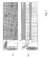
- Fig. 1 there are two component carriers (CC1 and CC2, also referred to as primary component carrier and secondary component carrier).
- CC1 and CC2 also referred to as primary component carrier and secondary component carrier.
- cross carrier scheduling it is possible to schedule for data transmission on CC2 by using a PDCCH on CC1. This is shown in the figure by the horizontally hatched areas (diagonally horizontally PDCCH on CC1, and horizontally hatched data area on CC2).
- the white areas of the third OFDM symbol represents some radio resources that are not used (and cannot be used), and thereby wasted at the cost of simplicity. This would in general apply to cases where cross-carrier scheduling happens with control area of scheduling PDCCH is larger than control area of scheduled PDSCH. Scheduling within own carrier would not cause any waste of radio resources, as mentioned above.
- the reverse operation is not excluded, where a PDCCH on a component carrier schedules data resources on the primary component carrier (or more general on a carrier with a longer PDCCH length, also Fig. 1 ).
- the same PCFICH information should be applied, but the eNB should not remove any information belonging to the control channel part.
- the UE will put erroneous data into the soft buffer in 1/12 of the places (but 11/12 of the data will be correct, the erroneous bits correspond to the REs in the first or in the first two OFDM symbols of the PDSCH allocation), and the result will be a minor link performance degradation, which channel coding might recover from.
- H-ARQ will be able to recover the data through retransmissions. It should be noted that in this case there is no rate matching modification, only some bits are punctured while the position of the others outside of the PDCCH area is not changed. It might be noted that the above issues of the proposed solution like throughput loss or partial soft buffer corruption might be alternatively avoided by coordinated usage of PDCCH resources on the CCs participating in cross component carrier scheduling. In this case by coordinated usage of the PDCCH resources on multiple carriers the eNB ensures that cross-CC scheduled carriers have the same PDCCH area length.
- both the PCFICH linking and PDSCH puncturing scheme would need to be standardized (meaning that data should have lower priority than control when/if these are in overlapping areas).
- Primary Component Carrier refers to the primary carrier for all UEs in a cell: the Primary Component Carrier has full control/common channel cell coverage. Such a Component Carrier may also represent the (only) carrier for UE camping and initial access, hereby referring to the notion of an Anchor Component Carrier. It should be noted that the invention is also applicable when there is no notion of primary/secondary/anchor component carrier.
- Multiple Stand-alone Component Carriers in a Carrier Aggregation System may exist and take the role of an Anchor Component Carrier.
- Anchor Component Carrier may take the role of an Anchor Component Carrier.
- multiple Anchor Component Carriers can be supported as well using both the first and the second scheme.
- Clever eNB cross-CC scheduling implementation and/or Autonomous CC Selection techniques will allow for minimizing the occurrence of the secondary scheme, i.e., a situation in which the control area of the assigning PDCCH CC is shorter than the control area of the corresponding allocated PDSCH CC.
- the above PCFICH linking only kicks in and is used in some cases depending on the value of at least one of the following SNR/MCS/CQI/TBS/coding rate/number of code blocks of the CC with the allocated PDSCH. Otherwise, if one of the above quantities is in a predefined range, the solution is not used and the Rel'8 association of the PCFICH with PDSCH starting OFDM symbol on the same carrier is used.
- Fig. 2A shows a simplified configuration of a user equipment
- Fig. 2B shows a simplified configuration of an eNodeB as an example for a network control element.
- the UE 1 comprises a receiver 11 and a processor 12.
- the receiver 11 is configured to receive signaling on a first component carrier (CC1) and at least a second component carrier (CC2) (such as shown in Fig. 1 , for example), wherein each component carrier comprises a control area and a data area.
- a control format indicator (for example, the PCFICH described above) indicates the size of the control area in the first component carrier
- the processor uses the control format indicator for the first component carrier also for the second component carrier in case cross component carrier scheduling is applied, as also described above in connection with Fig. 1 .
- Fig. 2B shows an eNodeB 2 comprising a processor 21 and a sender 22.
- the processor 21 is configured to allocate resources on the first component carrier and at least the second component carrier.
- the component carriers as well as the control format indicator e.g., PCFICH
- the processor 21 uses the control format indicator for the first component carrier also for the second component carrier in case cross component carrier scheduling is applied.
- the sender 22 may send signaling on the first and second component carrier based on the scheduling as effected by the processor.
- Figs. 3A and 3B show methods according to embodiments of the present invention.
- Fig. 3A shows the method as carried out, for example, at the UE.
- step S1 signaling on a first component carrier and at least a second component carrier is received.
- the component carriers as well as the control format indicator e.g., PCFICH
- the control format indicator for the first component carrier is also used for the second component carrier in case cross component carrier scheduling is applied. That is, for the second component carrier, the same control format indicator as for the first component carrier is used, so that the UE may start demodulation based thereon.
- Fig. 3B shows the method as carried out on the network side, e.g., at the eNodeB.
- resources are allocated on a first component carrier and at least a second component carrier.
- the component carriers as well as the control format indicator e.g., PCFICH
- the control format indicator for the first component carrier is also used for the second component carrier in case cross component carrier scheduling is applied.
- using may mean that the data channels (e.g. PDSCH) are scheduled on the second component carrier such that the same size of the control area and the same size of the data area are assumed for the first and the second component carriers.
- an apparatus which comprises a receiver configured to receive data/signaling on a first component carrier and data/signaling on at least a second component carrier, wherein each component carrier comprises a control area and a data area, wherein a control format indicator indicates the size of the control area in the first component carrier, and a processor configured to use the control format indicator for the first component carrier also for the second component carrier in case of cross carrier scheduling.
- the first aspect may be modified as follows:
- the processor may be configured to use the control format indicator for determining a location of a data channel in the second component carrier.
- the apparatus may be or may be part of a user equipment.
- an apparatus which comprises a processor configured to allocate resources on a first component carrier and at least a second component carrier, wherein each component carrier comprises a control area and a data area, wherein a control format indicator indicates the size of the control area in the first component carrier, and the processor is configured to use the control format indicator for the first component carrier also for the second component carrier in case of cross carrier scheduling.
- the second aspect may be modified as follows:
- the apparatus may further comprises a sender configured to send data/signaling on a first component carrier and data/signaling on at least a second component carrier.
- the processor may be configured to use the control format indicator for determining a location of a data channel in the second component carrier.
- the processor may be configured to not use a resource on the second component area for a data channel in case the resource in the second component area is used for control signaling.
- the processor may be configured to use the same control area size for component carriers in case of cross carrier scheduling.
- the processor may be configured to use the same control format indicator for the first component carrier and the at least second component carrier depending on the value of at least one of the following signal-noise-ratio (SNR)/modulation and coding scheme (MCS)/channel quality indicator (CQI)/transport block size (TBS)/coding rate/number of code blocks of the component carrier on which a data channel is allocated.
- SNR signal-noise-ratio
- MCS modulation and coding scheme
- CQI channel quality indicator
- TSS transport block size
- the apparatus is or is part of a network control element.
- the network control element may be an eNode-B or a central unit.
- Control information (e.g., a PDCCH) may be located in the control area of the first component carrier, the control information indicating the data channel on the second component carrier.
- the control format indicator may be included in a physical control format indicator channel.
- the control information may be included in a physical downlink control channel.
- the data channel may be a physical downlink shared channel.
- a method which comprises receiving data/signaling on a first component carrier and data/signaling on at least a second component carrier, wherein each component carrier comprises a control area and a data area, a control format indicator indicates the size of the control area in the first component carrier, and using the control format indicator for the first component carrier also for the second component carrier in case of cross carrier scheduling.
- the third aspect may be modified as follows:
- the method may further comprise using the control format indicator for determining a location of a data channel in the second component carrier.
- a method which comprises allocating resources on a first component carrier and at least a second component carrier, wherein each component carrier comprises a control area and a data area, wherein a control format indicator indicates the size of the control area in the first component carrier, and using the control format indicator for the first component carrier also for the second component carrier in case of cross carrier scheduling.
- the fourth aspect may be modified as follows:
- the method may further comprise using the control format indicator for determining a location of a data channel in the second component carrier.
- the method may further comprise not using a resource on the second component area for a data channel in case the resource in the second component area is used for control signaling.
- the method may further comprise using the same control area size for component carriers in case of cross carrier scheduling.
- the method may further comprise using the same control format indicator for the first component carrier and the at least second component carrier depending on the value of at least one of the following signal-noise-ratio (SNR)/modulation and coding scheme (MCS)/channel quality indicator (CQI)/transport block size (TBS)/coding rate/number of code blocks of the component carrier on which a data channel is allocated.
- SNR signal-noise-ratio
- MCS modulation and coding scheme
- CQI channel quality indicator
- TSS transport block size
- Control information may be located in the control area of the first component carrier the control information indicating the data channel on the second component carrier.
- the control format indicator may be included in a physical control format indicator channel.
- the control information may be included in a physical downlink control channel.
- the data channel may be a physical downlink shared channel.
- a computer program product which comprises code means for performing a method according to any one of the third and fourth aspects and their modifications when run on a computer.
- the computer program product is embodied on a computer-readable medium.
- the computer program product may be directly loadable into an internal memory of the computer.
- an apparatus which comprises means for receiving data/signaling on a first component carrier and data/signaling on at least a second component carrier, wherein each component carrier comprises a control area and a data area, wherein a control format indicator indicates the size of the control area in the first component carrier, and means for using the control format indicator for the first component carrier also for the second component carrier in case of cross carrier scheduling.
- the apparatus may further comprise means for using the control format indicator for determining a location of a data channel in the second component carrier.
- an apparatus which comprises means for allocating resources on a first component carrier and at least a second component carrier, wherein each component carrier comprises a control area and a data area, wherein a control format indicator indicates the size of the control area in the first component carrier, and means for using the control format indicator for the first component carrier also for the second component carrier in case of cross carrier scheduling.
- the seventh aspect may be modified as follows:
- the apparatus may further comprise means for sending data/signaling on a first component carrier and data/signaling on at least a second component carrier.
- the apparatus may further comprise means for using the control format indicator for determining a location of a data channel in the second component carrier.
- the apparatus may further comprise means for not using a resource on the second component area for a data channel in case the resource in the second component area is used for control signaling.
- the apparatus may further comprise means for using the same control area size for component carriers in case of cross carrier scheduling.
- the apparatus may further comprise means for using the same control format indicator for the first component carrier and the at least second component carrier depending on the value of at least one of the following signal-noise-ratio (SNR)/modulation and coding scheme (MCS)/channel quality indicator (CQI)/transport block size (TBS)/coding rate/number of code blocks of the component carrier on which a data channel is allocated.
- SNR signal-noise-ratio
- MCS modulation and coding scheme
- CQI channel quality indicator
- TSS transport block size
Landscapes
- Engineering & Computer Science (AREA)
- Signal Processing (AREA)
- Computer Networks & Wireless Communication (AREA)
- Mobile Radio Communication Systems (AREA)
Abstract
An apparatus is described which comprises a receiver configured to receive data/signaling on a first component carrier and data/signaling on at least a second component carrier, wherein each component carrier comprises a control area and a data area, wherein a control format indicator indicates the size of the control area in the first component carrier, and a processor configured to use the control format indicator for the first component carrier also for the second component carrier in case of cross carrier scheduling.
Description
- The present invention relates to an apparatus, method and computer program product for controlling a cross-component carrier scheduling.
- The following meanings for the abbreviations used in this specification apply:
3GPP 3rd generation partnership project CC Component carrier CQI Channel quality indicator C-RNTI Cell radio network temporary identity CRC Cyclic redundancy checksum DL Downlink eNode-B LTE base station (also referred to as eNB) H-ARQ: Hybrid Automatic Repeat Request LTE Long term evolution LTE-A LTE-Advanced MCS Modulation and coding scheme MIMO Multiple input multiple output OFDM Orthogonal frequency division mulitplexing PCFICH Physical control format indicator channel PDCCH Physical downlink control channel PDSCH Physical Downlink Shared Channel PHICH Physical H-ARQ indicator channel PRB Physical Resource Block RB Resource Block RE Resource Element Rel Release RLC Radio link control RRC Radio resource control RSRQ Reference signal received quality SNR Signal-noise ratio SPS-RNTI Semi-persistent scheduling radio network temporary identity TBS Transport block size TS Technical specification TTI: Transmission Time Interval UE User equipment UL Uplink - The present application is related to the further evolution of 3GPP long term evolution (LTE), also known as LTE-Advanced. This further evolution is targeted at increasing the peak data rates of LTE. In LTE it is possible to achieve peak data rates up to 300 Mbps (with a 4x4 MIMO configuration). For LTE-Advanced, the peak data rates are tentatively set to a much higher value (around a factor 5 higher), meaning that means to extend the possible data rates needs to be found.
- One of the techniques considered for this is the addition of multiple component carriers, meaning that a number of LTE Rel'8 carriers are "concatenated" to provide a larger bandwidth combined carrier. In the current concept thinking, the component carriers being merged/used at the same time may or may not be adjacent. The central element of the aggregation of the component carriers is to (1) increase peak data rate, and (2) allow for concatenation of fragments of frequency resources in a scattered frequency spectrum (for instance in case of spectrum refarming). The present application is related to the concatenation of the component carriers, and the handling of control signaling related to this.
- The Rel'8 structure when a UE determines whether it is being scheduled is based on a sequence of estimations/detections, which in the end leads to decoding of a data set intended for the UE. As a starting point, the time-frequency structure for scheduling a UE is divided into two pieces: a region for control channel signaling, and a data-area for the downlink shared channel (which is dynamically shared for transmission of data to different UEs). The control channel part can occupy between 1 and 3 OFDM symbols (or between 2 and 4 for lower LTE system bandwidths) out of a total of 14 OFDM symbols (which in total covers 1 ms transmission time interval - TTI, the assumption used here is normal/short cyclic prefix operation for the long/extended cyclic prefix operation there are 12 OFDM symbols per subframe). The control channel part of the 1 ms time period is used to carry the following channels:
- PCFICH - physical control format indicator channel (tells the UE the division between control and data for this TTI. Possible values are 1-3 (2-4 for 1.4 MHz LTE Rel-8 bandwidth).
- PHICH - Physical H-ARQ indicator channel (used to indicate to a UE whether the uplink transmission was OK or not).
- PDCCH - Physical downlink control channel (used to indicate resource allocations (both uplink and downlink allocations).
- Seen from a UE perspective, the UE will in the decoding/detection process initiate the following actions (for a downlink allocation/grant):
- UE evaluates the content of the PCFICH to find the amounts of resources for control and data respectively.
- Following this, the UE starts searching the PDCCH for a resource allocation (DL resource allocation is presumed). This happens whenever one of the IDs of the UE (C-RNTI, SPS C-RNTI) matches one of the PDCCH in the PDCCH search space. The process used for identifying the UE is through CRC masking on the PDCCH payload information.
- When a resource allocation has been found on a PDCCH, the UE will simply start demodulating the PDSCH using the originally estimated division between control and data areas. As the correct PDCCH reception is also dependent on the correct PCFICH decoding, there is a very low probability that a UE attempts to decode a PDSCH without this UE actually being scheduled in the first place.
- Now, to expand the peak data rate and to allow for a more fragmented spectrum, some proposals for LTE-Advanced consider the possibility to use multiple aggregated component carriers. Based on some processing limitations on the PDCCH blind decoding, some companies have suggested having independent component carriers, which operate on their own, meaning that each of them is free to determine the division between control and data (basically the PCFICH for two aggregated component carriers can have different values). On top of this, some companies have suggested to allow for cross component carrier scheduling (meaning for example the PDCCH on
component carrier # 1 can schedule a PDSCH oncomponent carrier # 2.). - This approach may seem feasible, but consider the decoding order, the decoding order for the UE is as follows:
- UE evaluates the content of the PCFICH on CC1 (it is assumed to only search
component carrier # 1 for an allocation) to find the amounts of resources for control and data respectively (on CC1). - Following this, the UE starts searching the PDCCH on CC1 for a resource allocation
- When a resource allocation has been found on a PDCCH on CC1, the UE will find out that it has been scheduled on CC2, meaning that it will have to introduce an intermediate step.
- UE decodes the PCFICH for CC2 to determine the division between control and data areas.
- The UE will simply start demodulating the PDSCH on CC2, assuming the data area for CC2.
- In this case there is a potential problem caused by the case where the UE misinterprets the PCFICH value on CC2. If this happens, the UE will use the wrong assumption for the starting point of the data area, and start performing the rate de-matching (and PDSCH-to-RE de-mapping) using an erroneous assumption, and the bits for the data packet are put into the wrong places (meaning that the H-ARQ soft combining buffer gets corrupted). There is no way for an eNB to detect that this situation has happened, and the only way of recovering is to trigger a RLC retransmission (which might cause the service running to be slowed down). Further, there are no mechanisms to ensure/validate the estimate of the PCFICH value on the CC2.
- Thus, it is an object of the present invention to overcome the above problem of the prior art.
- According to several embodiments of the present invention, this is accomplished by an apparatus and a method by which receive data/signaling on a first component carrier and data/signaling on at least a second component carrier are received, wherein each component carrier comprises a control area and a data area, wherein a control format indicator indicates the size of the control area in the first component carrier, and the control format indicator for the first component carrier is also used for the second component carrier in case of cross carrier scheduling.
- According to several embodiments of the present invention, an apparatus and a method is provided, by which resources are allocated on a first component carrier and at least a second component carrier, wherein each component carrier comprises a control area and a data area, wherein a control format indicator indicates the size of the control area in the first component carrier, and the control format indicator for the first component carrier is also used for the second component carrier in case of cross carrier scheduling.
- These and other objects, features, details, advantages and technical effects will become more fully apparent from the following detailed description of embodiments of the present invention which is to be taken in conjunction with the appended drawings, in which:
-
Fig. 1 illustrates a principle according to some embodiments of the present invention; -
Fig. 2A and 2B show simplified structures of a user equipment (UE) and an eNode-B according to some embodiments of the present invention; and -
Fig. 3A and3B show processes carried out by user equipment (UE) and an eNode-B according to some embodiments of the present invention; - In the following, description will be made to embodiments of the present invention. It is to be understood, however, that the description is given by way of example only, and that the described embodiments are by no means to be understood as limiting the present invention thereto.
- According to embodiments of the present application, a rule is introduced that binds the data area available for the PDSCH to the PCFICH value of the component carrier which carries the scheduling information. That is, in case a UE detects a PDCCH indicating a downlink allocation on another component carrier, the UE shall assume that the other component carrier is using the same PCFICH value and start data demodulation according to this assumption.
- In other words, according to embodiments of the present invention it is proposed to start a PDSCH bit mapping/transmission from the position determined by the PCFICH carried on the component carrier (CC) that also carries the corresponding PDCCH.
- In order to further describe the above concept according to embodiments of the present invention, it is referred to
Fig. 1 . InFig. 1 , there are two component carriers (CC1 and CC2, also referred to as primary component carrier and secondary component carrier). In this example, there are 3 OFDM (orthogonal frequency division multiplexing) symbols reserved for the first component carrier's control area (and 11 OFDM symbols for data), while the second component carrier only reserves 2 OFDM symbols for the control channel (and 12 OFDM symbols for data). That is, PCFICH 1 for the first component carrier CC1 indicates 3, whereas PCICH_2 for the second component carrier CC2 indicates 2. - By using cross carrier scheduling it is possible to schedule for data transmission on CC2 by using a PDCCH on CC1. This is shown in the figure by the horizontally hatched areas (diagonally horizontally PDCCH on CC1, and horizontally hatched data area on CC2).
- With the concept according to the present embodiment as described above, the data area for the cross component carrier scheduled PDSCH should maintain the assumption of the PCFICH being the same as the PCFICH of the originating component carrier. That is, for both component carriers (the point of view of a terminal which received PDCCH on CC1), only PCFICH 1 (=3) is used as the PCFICH.
- In this way, there might be less potential for optimizing the data capacity of the secondary component carrier, but the potential H-ARQ buffer corruption is not an issue anymore (due to the validity check through linking between PCFICH_1 and PDCCH on component carrier 1).
- It should be noted that a PDCCH on the secondary component carrier will still be able to allocate the full data area, so the loss of data capacity will only be seen when cross component carrier scheduling is applied.
- It should be noted that the white areas of the third OFDM symbol represents some radio resources that are not used (and cannot be used), and thereby wasted at the cost of simplicity. This would in general apply to cases where cross-carrier scheduling happens with control area of scheduling PDCCH is larger than control area of scheduled PDSCH. Scheduling within own carrier would not cause any waste of radio resources, as mentioned above.
- Also, it should be noted that the reverse operation is not excluded, where a PDCCH on a component carrier schedules data resources on the primary component carrier (or more general on a carrier with a longer PDCCH length, also
Fig. 1 ). In this case, the same PCFICH information should be applied, but the eNB should not remove any information belonging to the control channel part. In such a situation, the UE will put erroneous data into the soft buffer in 1/12 of the places (but 11/12 of the data will be correct, the erroneous bits correspond to the REs in the first or in the first two OFDM symbols of the PDSCH allocation), and the result will be a minor link performance degradation, which channel coding might recover from. If this is not the case, H-ARQ will be able to recover the data through retransmissions. It should be noted that in this case there is no rate matching modification, only some bits are punctured while the position of the others outside of the PDCCH area is not changed. It might be noted that the above issues of the proposed solution like throughput loss or partial soft buffer corruption might be alternatively avoided by coordinated usage of PDCCH resources on the CCs participating in cross component carrier scheduling. In this case by coordinated usage of the PDCCH resources on multiple carriers the eNB ensures that cross-CC scheduled carriers have the same PDCCH area length. - For this secondary scheme with overlapping control and data to operate properly, both the PCFICH linking and PDSCH puncturing scheme would need to be standardized (meaning that data should have lower priority than control when/if these are in overlapping areas).
- The notion of Primary Component Carrier refers to the primary carrier for all UEs in a cell: the Primary Component Carrier has full control/common channel cell coverage. Such a Component Carrier may also represent the (only) carrier for UE camping and initial access, hereby referring to the notion of an Anchor Component Carrier. It should be noted that the invention is also applicable when there is no notion of primary/secondary/anchor component carrier.
- Multiple Stand-alone Component Carriers in a Carrier Aggregation System may exist and take the role of an Anchor Component Carrier. As the approach described above is UE-related rather than Carrier-related, multiple Anchor Component Carriers can be supported as well using both the first and the second scheme.
- Clever eNB cross-CC scheduling implementation and/or Autonomous CC Selection techniques will allow for minimizing the occurrence of the secondary scheme, i.e., a situation in which the control area of the assigning PDCCH CC is shorter than the control area of the corresponding allocated PDSCH CC.
- In another embodiment, the above PCFICH linking only kicks in and is used in some cases depending on the value of at least one of the following SNR/MCS/CQI/TBS/coding rate/number of code blocks of the CC with the allocated PDSCH. Otherwise, if one of the above quantities is in a predefined range, the solution is not used and the Rel'8 association of the PCFICH with PDSCH starting OFDM symbol on the same carrier is used.
- For example, if code rate is too high or the transport block is too large, the scheme is not used.
- In the following, some embodiments implementing the processes described above are described with respect to
Fig. 2A and 2B . In particular,Fig. 2A shows a simplified configuration of a user equipment, andFig. 2B shows a simplified configuration of an eNodeB as an example for a network control element. - In particular, the
UE 1 comprises areceiver 11 and aprocessor 12. Thereceiver 11 is configured to receive signaling on a first component carrier (CC1) and at least a second component carrier (CC2) (such as shown inFig. 1 , for example), wherein each component carrier comprises a control area and a data area. A control format indicator (for example, the PCFICH described above) indicates the size of the control area in the first component carrier The processor uses the control format indicator for the first component carrier also for the second component carrier in case cross component carrier scheduling is applied, as also described above in connection withFig. 1 . -
Fig. 2B shows aneNodeB 2 comprising aprocessor 21 and asender 22. In particular, theprocessor 21 is configured to allocate resources on the first component carrier and at least the second component carrier. The component carriers as well as the control format indicator (e.g., PCFICH) are the same as described above. Theprocessor 21 uses the control format indicator for the first component carrier also for the second component carrier in case cross component carrier scheduling is applied. Then, thesender 22 may send signaling on the first and second component carrier based on the scheduling as effected by the processor. -
Figs. 3A and3B show methods according to embodiments of the present invention. -
Fig. 3A shows the method as carried out, for example, at the UE. In step S1, signaling on a first component carrier and at least a second component carrier is received. The component carriers as well as the control format indicator (e.g., PCFICH) are the same as described above. In step S2, the control format indicator for the first component carrier is also used for the second component carrier in case cross component carrier scheduling is applied. That is, for the second component carrier, the same control format indicator as for the first component carrier is used, so that the UE may start demodulation based thereon. -
Fig. 3B shows the method as carried out on the network side, e.g., at the eNodeB. In step S11, resources are allocated on a first component carrier and at least a second component carrier. The component carriers as well as the control format indicator (e.g., PCFICH) are the same as described above. In step S12, the control format indicator for the first component carrier is also used for the second component carrier in case cross component carrier scheduling is applied. In this case, using may mean that the data channels (e.g. PDSCH) are scheduled on the second component carrier such that the same size of the control area and the same size of the data area are assumed for the first and the second component carriers. - Hence, in this way, a reliable detection of PDSCH can be ensured even in case of cross component carrier scheduling.
- According to a first aspect of several embodiments of the invention, an apparatus is provided which comprises
a receiver configured to receive data/signaling on a first component carrier and data/signaling on at least a second component carrier, wherein each component carrier comprises a control area and a data area,
wherein a control format indicator indicates the size of the control area in the first component carrier, and
a processor configured to use the control format indicator for the first component carrier also for the second component carrier in case of cross carrier scheduling. - The first aspect may be modified as follows:
- The processor may be configured to use the control format indicator for determining a location of a data channel in the second component carrier.
- The apparatus may be or may be part of a user equipment.
- According to a second aspect of several embodiments of the invention, an apparatus is provided which comprises
a processor configured to allocate resources on a first component carrier and at least a second component carrier, wherein each component carrier comprises a control area and a data area, wherein
a control format indicator indicates the size of the control area in the first component carrier, and
the processor is configured to use the control format indicator for the first component carrier also for the second component carrier in case of cross carrier scheduling. - The second aspect may be modified as follows:
- The apparatus may further comprises a sender configured to send data/signaling on a first component carrier and data/signaling on at least a second component carrier.
- The processor may be configured to use the control format indicator for determining a location of a data channel in the second component carrier.
- The processor may be configured to not use a resource on the second component area for a data channel in case the resource in the second component area is used for control signaling.
- The processor may be configured to use the same control area size for component carriers in case of cross carrier scheduling.
- The processor may be configured to use the same control format indicator for the first component carrier and the at least second component carrier depending on the value of at least one of the following signal-noise-ratio (SNR)/modulation and coding scheme (MCS)/channel quality indicator (CQI)/transport block size (TBS)/coding rate/number of code blocks of the component carrier on which a data channel is allocated.
- The apparatus is or is part of a network control element.
- The network control element may be an eNode-B or a central unit.
- Control information (e.g., a PDCCH) may be located in the control area of the first component carrier, the control information indicating the data channel on the second component carrier.
- The control format indicator may be included in a physical control format indicator channel.
- The control information may be included in a physical downlink control channel.
- The data channel may be a physical downlink shared channel.
- According to a third aspect of several embodiments of the invention, a method is provided which comprises
receiving data/signaling on a first component carrier and data/signaling on at least a second component carrier,
wherein each component carrier comprises a control area and a data area, a control format indicator indicates the size of the control area in the first component carrier, and
using the control format indicator for the first component carrier also for the second component carrier in case of cross carrier scheduling. - The third aspect may be modified as follows:
- The method may further comprise
using the control format indicator for determining a location of a data channel in the second component carrier. - According to a fourth aspect of several embodiments of the invention, a method is provided which comprises
allocating resources on a first component carrier and at least a second component carrier, wherein each component carrier comprises a control area and a data area, wherein
a control format indicator indicates the size of the control area in the first component carrier, and
using the control format indicator for the first component carrier also for the second component carrier in case of cross carrier scheduling. - The fourth aspect may be modified as follows:
- The method may further comprise
using the control format indicator for determining a location of a data channel in the second component carrier. - The method may further comprise
not using a resource on the second component area for a data channel in case the resource in the second component area is used for control signaling. - The method may further comprise
using the same control area size for component carriers in case of cross carrier scheduling. - The method may further comprise
using the same control format indicator for the first component carrier and the at least second component carrier depending on the value of at least one of the following signal-noise-ratio (SNR)/modulation and coding scheme (MCS)/channel quality indicator (CQI)/transport block size (TBS)/coding rate/number of code blocks of the component carrier on which a data channel is allocated. - Control information may be located in the control area of the first component carrier the control information indicating the data channel on the second component carrier.
- The control format indicator may be included in a physical control format indicator channel.
- The control information may be included in a physical downlink control channel.
- The data channel may be a physical downlink shared channel.
- According to a fifth aspect of several embodiments of the present invention, a computer program product is provided which comprises code means for performing a method according to any one of the third and fourth aspects and their modifications when run on a computer.
- The computer program product is embodied on a computer-readable medium.
- The computer program product may be directly loadable into an internal memory of the computer.
- According to a sixth aspect of several embodiments of the invention, an apparatus is provided which comprises
means for receiving data/signaling on a first component carrier and data/signaling on at least a second component carrier, wherein each component carrier comprises a control area and a data area,
wherein a control format indicator indicates the size of the control area in the first component carrier, and
means for using the control format indicator for the first component carrier also for the second component carrier in case of cross carrier scheduling. - The apparatus may further comprise means for using the control format indicator for determining a location of a data channel in the second component carrier.
- According to a seventh aspect of several embodiments of the invention, an apparatus is provided which comprises
means for allocating resources on a first component carrier and at least a second component carrier, wherein each component carrier comprises a control area and a data area, wherein
a control format indicator indicates the size of the control area in the first component carrier, and
means for using the control format indicator for the first component carrier also for the second component carrier in case of cross carrier scheduling. - The seventh aspect may be modified as follows:
- The apparatus may further comprise means for sending data/signaling on a first component carrier and data/signaling on at least a second component carrier.
- The apparatus may further comprise means for using the control format indicator for determining a location of a data channel in the second component carrier.
- The apparatus may further comprise means for not using a resource on the second component area for a data channel in case the resource in the second component area is used for control signaling.
- The apparatus may further comprise means for using the same control area size for component carriers in case of cross carrier scheduling.
- The apparatus may further comprise means for using the same control format indicator for the first component carrier and the at least second component carrier depending on the value of at least one of the following signal-noise-ratio (SNR)/modulation and coding scheme (MCS)/channel quality indicator (CQI)/transport block size (TBS)/coding rate/number of code blocks of the component carrier on which a data channel is allocated. Further modifications of the sixth and seventh aspects are similar as those of the first and second aspects.
- It is to be understood that any of the above modifications can be applied singly or in combination to the respective aspects and/or embodiments to which they refer, unless they are explicitly stated as excluding alternatives.
- For the purpose of the present invention as described herein above, it should be noted that
- method steps likely to be implemented as software code portions and being run using a processor at a network element or terminal (as examples of devices, apparatuses and/or modules thereof, or as examples of entities including apparatuses and/or modules therefore), are software code independent and can be specified using any known or future developed programming language as long as the functionality defined by the method steps is preserved;
- generally, any method step is suitable to be implemented as software or by hardware without changing the idea of the invention in terms of the functionality implemented;
- method steps and/or devices, units or means likely to be implemented as hardware components at the above-defined apparatuses, or any module(s) thereof, (e.g., devices carrying out the functions of the apparatuses according to the embodiments as described above, UE, eNode-B etc. as described above) are hardware independent and can be implemented using any known or future developed hardware technology or any hybrids of these, such as MOS (Metal Oxide Semiconductor), CMOS (Complementary MOS), BiMOS (Bipolar MOS), BiCMOS (Bipolar
- devices, units or means (e.g. the above-defined apparatuses, or any one of their respective means) can be implemented as individual devices, units or means, but this does not exclude that they are implemented in a distributed fashion throughout the system, as long as the functionality of the device, unit or means is preserved;
- an apparatus may be represented by a semiconductor chip, a chipset, or a (hardware) module comprising such chip or chipset; this, however, does not exclude the possibility that a functionality of an apparatus or module, instead of being hardware implemented, be implemented as software in a (software) module such as a computer program or a computer program product comprising executable software code portions for execution/being run on a processor;
- a device may be regarded as an apparatus or as an assembly of more than one apparatus, whether functionally in cooperation with each other or functionally independently of each other but in a same device housing, for example.
- It is noted that the embodiments and examples described above are provided for illustrative purposes only and are in no way intended that the present invention is restricted thereto. Rather, it is the intention that all variations and modifications be included which fall within the spirit and scope of the appended claims.
Claims (15)
- An apparatus comprising
a receiver configured to receive data/signaling on a first component carrier and data/signaling on at least a second component carrier, wherein each component carrier comprises a control area and a data area,
wherein a control format indicator indicates the size of the control area in the first component carrier, and
a processor configured to use the control format indicator for the first component carrier also for the second component carrier in case of cross carrier scheduling. - The apparatus according to claim 1, wherein the processor is configured to use the control format indicator for determining a location of a data channel in the second component carrier.
- An apparatus comprising
a processor configured to allocate resources on a first component carrier and at least a second component carrier, wherein each component carrier comprises a control area and a data area, wherein
a control format indicator indicates the size of the control area in the first component carrier, and
the processor is configured to use the control format indicator for the first component carrier also for the second component carrier in case of cross carrier scheduling. - The apparatus according to claim 3, wherein the processor is configured to use the control format indicator for determining a location of a data channel in the second component carrier.
- The apparatus according to claim 3 or 4, wherein
the processor is configured to not use a resource on the second component area for a data channel in case the resource in the second component area is used for control signaling, and/or
wherein the processor is configured to use the same control area size for component carriers in case of cross carrier scheduling. - The apparatus according to one of the claims 3 to 5, wherein the processor is configured to use the same control format indicator for the first component carrier and the at least second component carrier depending on the value of at least one of the following signal-noise-ratio/modulation and coding scheme/channel quality indicator/transport block size/coding rate/number of code blocks of the component carrier on which a data channel is allocated.
- The apparatus according to any of the claims 1 to 6, wherein control information is located in the control area of the first component carrier, the control information indicating the data channel on the second component carrier.
- A method comprising
receiving data/signaling on a first component carrier and data/signaling on at least a second component carrier,
wherein each component carrier comprises a control area and a data area, a control format indicator [PCFICH] indicates the size of the control area in the first component carrier, and
using the control format indicator for the first component carrier also for the second component carrier in case of cross carrier scheduling. - The method according to claim 8, further comprising
using the control format indicator for determining a location of a data channel in the second component carrier. - A method comprising
allocating resources on a first component carrier and at least a second component carrier, wherein each component carrier comprises a control area and a data area, wherein
a control format indicator [PCFICH] indicates the size of the control area in the first component carrier, and
using the control format indicator for the first component carrier also for the second component carrier in case of cross carrier scheduling. - The method according to claim 10, further comprising
using the control format indicator for determining a location of a data channel in the second component carrier. - The method according to claim 10 or 11, further comprising
not using a resource on the second component area for a data channel in case the resource in the second component area is used for control signaling, and/or
using the same control area size for component carriers in case of cross carrier scheduling. - The method according to one of the claims 10 to 12, further comprising
using the same control format indicator for the first component carrier and the at least second component carrier depending on the value of at least one of the following signal-noise-ratio /modulation and coding scheme/channel quality indicator/transport block size/coding rate/number of code blocks of the component carrier on which a data channel is allocated. - The method according to any of the claims 8 to 13, wherein control information is located in the control area of the first component carrier the control information indicating the data channel on the second component carrier.
- A computer program product comprising code means for performing a method according to any one of claims 8 to 14 when run on a computer.
Priority Applications (1)
| Application Number | Priority Date | Filing Date | Title |
|---|---|---|---|
| EP09171993A EP2306782A1 (en) | 2009-10-01 | 2009-10-01 | LTE-Advanced coupling between PCFICH and associated PDSCH for cross-component carrier scheduling |
Applications Claiming Priority (1)
| Application Number | Priority Date | Filing Date | Title |
|---|---|---|---|
| EP09171993A EP2306782A1 (en) | 2009-10-01 | 2009-10-01 | LTE-Advanced coupling between PCFICH and associated PDSCH for cross-component carrier scheduling |
Publications (1)
| Publication Number | Publication Date |
|---|---|
| EP2306782A1 true EP2306782A1 (en) | 2011-04-06 |
Family
ID=41716662
Family Applications (1)
| Application Number | Title | Priority Date | Filing Date |
|---|---|---|---|
| EP09171993A Withdrawn EP2306782A1 (en) | 2009-10-01 | 2009-10-01 | LTE-Advanced coupling between PCFICH and associated PDSCH for cross-component carrier scheduling |
Country Status (1)
| Country | Link |
|---|---|
| EP (1) | EP2306782A1 (en) |
Cited By (11)
| Publication number | Priority date | Publication date | Assignee | Title |
|---|---|---|---|---|
| GB2486926A (en) * | 2011-06-02 | 2012-07-04 | Renesas Mobile Corp | Frequency hopping in license-exempt / shared bands |
| WO2012142123A3 (en) * | 2011-04-11 | 2013-06-13 | Qualcomm Incorporated | Transmission of control information for fdd-tdd carrier aggregation |
| WO2013135952A1 (en) * | 2012-03-14 | 2013-09-19 | Nokia Corporation | Aggregation for a new carrier type |
| US8675605B2 (en) | 2011-06-02 | 2014-03-18 | Broadcom Corporation | Frequency hopping in license-exempt/shared bands |
| WO2014047072A1 (en) * | 2012-09-18 | 2014-03-27 | Trueposition, Inc. | Overlay network-based location of e-utran devices |
| US8711790B2 (en) | 2011-02-11 | 2014-04-29 | Nokia Corporation | DL control channel structure enhancement |
| TWI466557B (en) * | 2011-04-29 | 2014-12-21 | Acer Inc | Method of handling soft buffer for carrier aggregation and related communication device |
| US8917679B2 (en) | 2011-08-16 | 2014-12-23 | Nokia Corporation | Method for signaling the overlap of downlink control and data channels |
| EP2896174A4 (en) * | 2012-09-17 | 2016-06-29 | Broadcom Corp | PHY CONNECTION SIGNALING FOR CABLE NETWORKS |
| US9763246B2 (en) | 2012-06-12 | 2017-09-12 | Qualcomm Incorporated | Transport block size determination in new carrier type in LTE |
| CN109451854A (en) * | 2017-08-11 | 2019-03-08 | 北京小米移动软件有限公司 | A kind of cross-carrier dispatching method and device |
-
2009
- 2009-10-01 EP EP09171993A patent/EP2306782A1/en not_active Withdrawn
Non-Patent Citations (3)
| Title |
|---|
| HUAWEI: "Issues on Cross-Carrier PDCCH Indication for Carrier Aggregation", 3GPP DRAFT; R1-093047 ISSUES ON CROSS-CARRIER PDCCH INDICATION FOR CARRIER AGGREGATION, 3RD GENERATION PARTNERSHIP PROJECT (3GPP), MOBILE COMPETENCE CENTRE ; 650, ROUTE DES LUCIOLES ; F-06921 SOPHIA-ANTIPOLIS CEDEX ; FRANCE, no. Shenzhen, China; 20090818, 18 August 2009 (2009-08-18), XP050351439 * |
| LG ELECTRONICS: "Cross carrier scheduling by PDCCH for multiple carrier aggregation in LTE-Advanced", 3GPP DRAFT; R1-093249 LTEA_CROSS CC SCHEDULING, 3RD GENERATION PARTNERSHIP PROJECT (3GPP), MOBILE COMPETENCE CENTRE ; 650, ROUTE DES LUCIOLES ; F-06921 SOPHIA-ANTIPOLIS CEDEX ; FRANCE, no. Shenzhen, China; 20090818, 18 August 2009 (2009-08-18), XP050351586 * |
| PANASONIC: "PDCCH with cross component carrier assignment", 3GPP DRAFT; R1-093597(UPDATE OF R1-093464), 3RD GENERATION PARTNERSHIP PROJECT (3GPP), MOBILE COMPETENCE CENTRE ; 650, ROUTE DES LUCIOLES ; F-06921 SOPHIA-ANTIPOLIS CEDEX ; FRANCE, no. Shenzhen, China; 20090824, 24 August 2009 (2009-08-24), XP050388168 * |
Cited By (18)
| Publication number | Priority date | Publication date | Assignee | Title |
|---|---|---|---|---|
| US8711790B2 (en) | 2011-02-11 | 2014-04-29 | Nokia Corporation | DL control channel structure enhancement |
| US9042277B2 (en) | 2011-04-11 | 2015-05-26 | Qualcomm Incorporated | Transmission of control information for FDD-TDD carrier aggregation |
| WO2012142123A3 (en) * | 2011-04-11 | 2013-06-13 | Qualcomm Incorporated | Transmission of control information for fdd-tdd carrier aggregation |
| TWI466557B (en) * | 2011-04-29 | 2014-12-21 | Acer Inc | Method of handling soft buffer for carrier aggregation and related communication device |
| GB2486926B (en) * | 2011-06-02 | 2013-10-23 | Renesas Mobile Corp | Frequency hopping in license-exempt/shared bands |
| GB2486926A (en) * | 2011-06-02 | 2012-07-04 | Renesas Mobile Corp | Frequency hopping in license-exempt / shared bands |
| US8374212B2 (en) | 2011-06-02 | 2013-02-12 | Renesas Mobile Corporation | Frequency hopping in license-exempt/shared bands |
| US8675605B2 (en) | 2011-06-02 | 2014-03-18 | Broadcom Corporation | Frequency hopping in license-exempt/shared bands |
| US8917679B2 (en) | 2011-08-16 | 2014-12-23 | Nokia Corporation | Method for signaling the overlap of downlink control and data channels |
| US9065600B2 (en) | 2012-03-14 | 2015-06-23 | Nokia Technologies Oy | Aggregation for a new carrier type |
| WO2013135952A1 (en) * | 2012-03-14 | 2013-09-19 | Nokia Corporation | Aggregation for a new carrier type |
| US9763246B2 (en) | 2012-06-12 | 2017-09-12 | Qualcomm Incorporated | Transport block size determination in new carrier type in LTE |
| US9479621B2 (en) | 2012-09-17 | 2016-10-25 | Broadcom Corporation | Physical layer (PHY) link signaling for cable networks |
| EP2896174A4 (en) * | 2012-09-17 | 2016-06-29 | Broadcom Corp | PHY CONNECTION SIGNALING FOR CABLE NETWORKS |
| US9060281B2 (en) | 2012-09-18 | 2015-06-16 | Trueposition, Inc. | Overlay network-based location of E-UTRAN devices |
| WO2014047072A1 (en) * | 2012-09-18 | 2014-03-27 | Trueposition, Inc. | Overlay network-based location of e-utran devices |
| CN109451854A (en) * | 2017-08-11 | 2019-03-08 | 北京小米移动软件有限公司 | A kind of cross-carrier dispatching method and device |
| US11310820B2 (en) | 2017-08-11 | 2022-04-19 | Beijing Xiaomi Mobile Software Co., Ltd. | Cross-carrier scheduling method and device |
Similar Documents
| Publication | Publication Date | Title |
|---|---|---|
| US11805539B2 (en) | Method for operating user equipment in wireless communication system, and device therefor | |
| CN111108716B (en) | Method and apparatus for sending and receiving control information in a wireless communication system | |
| US10251169B2 (en) | Control channel allocation method, and apparatus for same | |
| US8553529B2 (en) | Method and apparatus for performing a HARQ operation in a multi-carrier system | |
| EP2448150B1 (en) | Reception and Transmissin of Acknowledgement signals in wireless communication systems | |
| CN104685808B (en) | Method and device for receiving ACK/NACK in wireless communication system | |
| US8441996B2 (en) | Method and apparatus for monitoring control channel in multiple carrier system | |
| KR101648584B1 (en) | Method of performing harq in multiple carrier system | |
| US9860023B2 (en) | Method and device for receiving ACK/NACK in wireless communication system | |
| US9300448B2 (en) | Search space for component carrier specific UL/DL configuration | |
| EP2675101A2 (en) | Method of handling downlink control information and a communication device related thereto | |
| WO2013077633A1 (en) | Method and apparatus for transmitting ack/nack signal in wireless communication system | |
| EP3094034A1 (en) | Control channels in wireless communication | |
| HK1174181A (en) | Signaling limitation of multiple payload sizes for resource assignments |
Legal Events
| Date | Code | Title | Description |
|---|---|---|---|
| PUAI | Public reference made under article 153(3) epc to a published international application that has entered the european phase |
Free format text: ORIGINAL CODE: 0009012 |
|
| AK | Designated contracting states |
Kind code of ref document: A1 Designated state(s): AT BE BG CH CY CZ DE DK EE ES FI FR GB GR HR HU IE IS IT LI LT LU LV MC MK MT NL NO PL PT RO SE SI SK SM TR |
|
| STAA | Information on the status of an ep patent application or granted ep patent |
Free format text: STATUS: THE APPLICATION IS DEEMED TO BE WITHDRAWN |
|
| 18D | Application deemed to be withdrawn |
Effective date: 20111007 |