EP2306700A2 - Color selecting method, image processing method, image processing apparatus, and recording medium - Google Patents
Color selecting method, image processing method, image processing apparatus, and recording medium Download PDFInfo
- Publication number
- EP2306700A2 EP2306700A2 EP10180961A EP10180961A EP2306700A2 EP 2306700 A2 EP2306700 A2 EP 2306700A2 EP 10180961 A EP10180961 A EP 10180961A EP 10180961 A EP10180961 A EP 10180961A EP 2306700 A2 EP2306700 A2 EP 2306700A2
- Authority
- EP
- European Patent Office
- Prior art keywords
- color
- chart
- patches
- light source
- designated
- Prior art date
- Legal status (The legal status is an assumption and is not a legal conclusion. Google has not performed a legal analysis and makes no representation as to the accuracy of the status listed.)
- Withdrawn
Links
- 238000000034 method Methods 0.000 title claims abstract description 80
- 238000012545 processing Methods 0.000 title claims abstract description 33
- 238000003672 processing method Methods 0.000 title claims abstract description 10
- 239000003086 colorant Substances 0.000 claims abstract description 90
- 238000007639 printing Methods 0.000 claims description 92
- 230000008569 process Effects 0.000 claims description 44
- 238000012937 correction Methods 0.000 claims description 36
- 230000003287 optical effect Effects 0.000 claims description 19
- 238000013507 mapping Methods 0.000 claims description 14
- 238000006243 chemical reaction Methods 0.000 claims description 8
- 239000007787 solid Substances 0.000 claims description 5
- 230000006870 function Effects 0.000 claims description 4
- 239000011159 matrix material Substances 0.000 description 22
- 238000012986 modification Methods 0.000 description 20
- 230000004048 modification Effects 0.000 description 20
- 239000008186 active pharmaceutical agent Substances 0.000 description 18
- 239000000976 ink Substances 0.000 description 15
- 238000003860 storage Methods 0.000 description 15
- 230000003595 spectral effect Effects 0.000 description 12
- 230000008859 change Effects 0.000 description 11
- 230000001419 dependent effect Effects 0.000 description 7
- 238000010586 diagram Methods 0.000 description 6
- 238000009826 distribution Methods 0.000 description 5
- 238000004891 communication Methods 0.000 description 3
- 238000005516 engineering process Methods 0.000 description 3
- 230000035945 sensitivity Effects 0.000 description 3
- BZHJMEDXRYGGRV-UHFFFAOYSA-N Vinyl chloride Chemical compound ClC=C BZHJMEDXRYGGRV-UHFFFAOYSA-N 0.000 description 2
- 230000006978 adaptation Effects 0.000 description 2
- 238000013461 design Methods 0.000 description 2
- 238000007641 inkjet printing Methods 0.000 description 2
- 230000002093 peripheral effect Effects 0.000 description 2
- 229920005989 resin Polymers 0.000 description 2
- 239000011347 resin Substances 0.000 description 2
- 238000002834 transmittance Methods 0.000 description 2
- 230000000007 visual effect Effects 0.000 description 2
- 238000005299 abrasion Methods 0.000 description 1
- 230000002411 adverse Effects 0.000 description 1
- 230000002457 bidirectional effect Effects 0.000 description 1
- 230000005540 biological transmission Effects 0.000 description 1
- 238000009792 diffusion process Methods 0.000 description 1
- 230000000694 effects Effects 0.000 description 1
- 238000011156 evaluation Methods 0.000 description 1
- 239000004744 fabric Substances 0.000 description 1
- 239000000835 fiber Substances 0.000 description 1
- 238000003384 imaging method Methods 0.000 description 1
- 238000010030 laminating Methods 0.000 description 1
- 238000004519 manufacturing process Methods 0.000 description 1
- 239000000463 material Substances 0.000 description 1
- 230000008450 motivation Effects 0.000 description 1
- 230000007935 neutral effect Effects 0.000 description 1
- 230000001681 protective effect Effects 0.000 description 1
- 238000002310 reflectometry Methods 0.000 description 1
- 230000035807 sensation Effects 0.000 description 1
- 229920003002 synthetic resin Polymers 0.000 description 1
- 239000000057 synthetic resin Substances 0.000 description 1
- WFKWXMTUELFFGS-UHFFFAOYSA-N tungsten Chemical compound [W] WFKWXMTUELFFGS-UHFFFAOYSA-N 0.000 description 1
- 229910052721 tungsten Inorganic materials 0.000 description 1
- 239000010937 tungsten Substances 0.000 description 1
- 238000011179 visual inspection Methods 0.000 description 1
Images








Classifications
-
- H—ELECTRICITY
- H04—ELECTRIC COMMUNICATION TECHNIQUE
- H04N—PICTORIAL COMMUNICATION, e.g. TELEVISION
- H04N1/00—Scanning, transmission or reproduction of documents or the like, e.g. facsimile transmission; Details thereof
- H04N1/46—Colour picture communication systems
- H04N1/56—Processing of colour picture signals
- H04N1/60—Colour correction or control
- H04N1/603—Colour correction or control controlled by characteristics of the picture signal generator or the picture reproducer
- H04N1/6033—Colour correction or control controlled by characteristics of the picture signal generator or the picture reproducer using test pattern analysis
-
- H—ELECTRICITY
- H04—ELECTRIC COMMUNICATION TECHNIQUE
- H04N—PICTORIAL COMMUNICATION, e.g. TELEVISION
- H04N1/00—Scanning, transmission or reproduction of documents or the like, e.g. facsimile transmission; Details thereof
- H04N1/46—Colour picture communication systems
- H04N1/56—Processing of colour picture signals
- H04N1/60—Colour correction or control
- H04N1/6083—Colour correction or control controlled by factors external to the apparatus
- H04N1/6088—Colour correction or control controlled by factors external to the apparatus by viewing conditions, i.e. conditions at picture output
Definitions
- the present invention relates to a color selecting method, an image processing method, an image processing apparatus, and a recording medium for printing a color chart having a plurality of color patches with a printing machine, and selecting one of the color patches of the color chart which is closest to a designated color.
- Inkjet printers are not only popular for private or home use, but nowadays also are widely used in commercial applications. Inkjet printers make it possible to print on POP (Point Of Purchase) posters, wall posters, large-size mediums such as outdoor advertisements and billboards, roll mediums, and thick hard mediums.
- POP Point Of Purchase
- wall posters large-size mediums such as outdoor advertisements and billboards, roll mediums, and thick hard mediums.
- print mediums there are a wide variety of print mediums (hereinafter also referred to as “mediums”) available for use in prints to meet various commercial demands.
- print mediums include paper mediums such as synthetic paper, thick paper, aluminum-evaporated paper, etc., resin mediums such as those made of vinyl chloride, PET, etc., and tarpaulin paper made of woven fiber cloth with synthetic resin films applied to both surfaces thereof.
- the method of adjusting a designated color referred to above comprises a method of making fine color adjustments of an area of interest in an image in order to bring the color into substantial conformity with a given color (designated color) designated by a color sample of color chips, while maintaining the color balance of the image as a whole.
- a given color designated color
- a method of selecting a plurality of candidate colors may be carried out by gradually changing the values of variables that can be controlled for print.
- variables include device-depending data such as C, M, Y, K data, R, B, G data, etc.
- Japanese Laid-Open Patent Publication No. 2000-217007 discloses a color selecting method of bringing the impression of a designated color displayed on a display device and the impression of a color printed by a printing machine into conformity with each other.
- Japanese Laid-Open Patent Publication No. 2000-217007 discloses a display window displayed on the display device where the displayed color is changeable and a printed color chart of 27 colors, which are thought to be close to a designated color that is displayed (see FIGS. 4 and 5 of Japanese Laid-Open Patent Publication No. 2000-217007 ).
- the color chart is made of color patches printed in colors having different C, M, Y, K values.
- a designated color falls outside the range of the gamut of a printing machine, it is physically impossible to reproduce the designated color.
- the designated color is replaced with a certain color (i.e., a color closest to the designated color) within the range of the gamut, and a gamut mapping process is carried out taking into account the color balance of the overall image.
- a gamut mapping process it is necessary to select an optimum gamut mapping process (hereinafter also referred to as "mapping process").
- observational environment in which a print is formed and an observational environment in which the print is displayed are different from each other, then the difference between the observational environments have to be taken into consideration.
- the types of observational light sources, the types of background colors, etc. have to be considered as variable factors, and the colors of color patches to be printed on a color chart need to be appropriately selected.
- selected colors may be different depending on color preference of each person.
- the color selecting method comprises the steps of designating a color comparing condition for the color chart, and generating image data to print the color chart in which color patches having colors corresponding respectively to different variables of the designated color comparing conditions are disposed adjacent to each other.
- the color comparing condition for the color chart refers to various conditions for comparing the colors of the color patches on the color chart to see if the colors are acceptable or not, and includes not only variables such as C, M, Y, K values, color values L*, a*, b*, etc., but also a type of observational light source, a gamut mapping process, etc.
- the type of observational light source includes not only the general name of a light source such as a tungsten lamp, a fluorescent lamp (F2, F6, F7, or the like), daylight D65, or the like, but also various data such as a color temperature, a spectral radiance distribution, etc.
- the color comparing condition includes the type of observational light source. The operator is thus able to select a color which is different under a different observational light source.
- the color comparing condition includes a background color.
- the operator is thus able to select a color in view of a change of spectral sensitivity characteristics of vision depending on the background color (so-called "chromatic adaptation).
- the color comparing condition includes lightness, saturation, and hue.
- the color comparing condition includes a gamut mapping process.
- the operator is thus able to select a color within the range of the gamut efficiently in a manner acceptable to the operator even if the designated color is a color outside the gamut.
- the step of generating image data generates the image data such that the color patches having colors gradually changed are disposed in a zigzag pattern. Therefore, the operator can continuously track down the colors of the color patches as they change and can easily select a color patch whose color is closest to the designated color.
- the step of generating image data generates the image data so as to include a guide line for observing the color patches along a route according to the zigzag pattern.
- the guide line allows the operator to easily and efficiently track down the colors of the color patches as they change.
- the one of the color patches whose color is closest to the designated color is selected under a predetermined observational light source from those of the color patches in the color chart which correspond to the type of the predetermined observational light source.
- the color selecting method further comprises the steps of printing the color chart after a color conversion thereof depending on a predetermined light source has been performed, and observing the color chart through color correction optical filters under an observational light source different from the predetermined light source, and selecting the one of the color patches whose color is closest to the designated color and selecting one of the color correction optical filters.
- the appearance of the colors of the color patches can thus freely be adjusted.
- the step of selecting one of the color correction optical filters selects the one of the color correction optical filters by evaluating the saturation of an achromatic solid area on the color chart, the achromatic solid area being provided separately from the color patches.
- an image processing method comprising the steps of designating a color comparing condition for a color chart having a plurality of color patches, generating image data to print the color chart in which color patches having colors corresponding respectively to different variables of the designated color comparing condition are disposed adjacent to each other, printing the color chart with a printing machine based on the generated image data, entering color values of a designated color, and converting colors of a print to be produced by the printing machine, based on color values of one of the color patches whose color is selected as a color closest to the designated color from the printed color chart and based on the entered color values of the designated color.
- an image processing method using the color selecting method described above comprising the steps of converting color values of the selected one of the color patches whose color is closest to the designated color into color values under the observational light source different from the predetermined light source, based on color information of the selected one of the color correction optical filters, entering color values of the designated color, and converting colors of a print to be produced by the printing machine, based on the color values under the observational light source different from the predetermined light source and based on the entered color values of the designated color.
- an image processing apparatus comprising a designator for designating a color comparing condition for a color chart having a plurality of color patches, a data generator for generating image data to print the color chart in which color patches having colors corresponding respectively to different variables of the color comparing condition designated by the designator are disposed adjacent to each other, a print controller for controlling a printing machine to print the color chart based on the image data generated by the data generator, and a color converter for converting colors of a print to be produced by the printing machine, based on color values of one of the color patches whose color is selected as a color closest to the designated color from the printed color chart and based on the entered color values of the designated color.
- an image processing apparatus comprising a patch color converter for converting color values of the one of the color patches whose color is closest to the designated color and which is selected by the color selecting method described above, into color values under the predetermined light source, based on color information of the selected one of the color correction optical filters, and a color converter for converting colors of a print to be produced by the printing machine, based on the color values under the observational light source different from the predetermined light source which are converted by the patch color converter and based on the entered color values of the designated color.
- a recording medium storing a program for enabling a computer to perform the functions of designating a color comparing condition for a color chart, generating image data to print the color chart in which color patches having colors corresponding respectively to different variables of the designated color comparing condition are disposed adjacent to each other, and printing the color chart based on the image data.
- color comparing conditions for the color chart are designated, and image data are generated to print the color chart in which color patches having colors corresponding respectively to different variables of the designated color comparing conditions are disposed adjacent to each other. Consequently, appropriate color comparing conditions can be designated depending on the situation in which the color selecting method is carried out, thereby allowing the operator to select a color efficiently and easily.
- FIG. 1 shows in perspective a printing system 10 incorporating an image processing apparatus 16 according to an embodiment of the present invention.
- the printing system 10 basically comprises a LAN 12, an editing apparatus 14, an image processing apparatus 16, a printing machine 18, and a colorimeter 20.
- the LAN 12 makes up a network constructed according to communication standards such as Ethernet (registered trademark) or the like.
- the editing apparatus 14 and the image processing apparatus 16 are connected to each other through the LAN 12 by a wired or wireless link.
- the editing apparatus 14 is capable of editing the arrangement of color images made up of characters, figures, pictures, photos, etc. on each of pages to be printed.
- the editing apparatus 14 generates electronic manuscripts in a page description language (hereinafter referred to as "PDL"), e.g., 8-bit image data in color channels of four colors (C, M, Y, K) or three colors (R, G, B).
- PDL page description language
- PDL refers to a language, which is descriptive of image information including format information, positional information, color information (including density information), etc., of characters, figures, etc., in a "page” that serves as an output unit for printing, displaying, or the like.
- PDF Portable Document Format according to ISO32000-1:2008 PostScript (registered trademark) of Adobe Systems, and XPS (XML Paper Specification).
- a color scanner not shown, is connected to the editing apparatus 14.
- the color scanner is capable of optically reading a color original set in position. Therefore, the editing apparatus 14 can acquire color image data from the color scanner, based on the color original read thereby, as the image data of an electronic manuscript.
- the image processing apparatus 16 converts the color image data of an electronic manuscript described by PDL and acquired from the editing apparatus 14 into raster image data (e.g., a type of bitmap image data), performs a desired image processing process, e.g., a color conversion process, an image scaling process, an image arranging process, etc. on the raster image data, converts the processed raster image data into a print control signal that matches the printing process of the printing machine 18, and sends the print control signal to the printing machine 18.
- raster image data e.g., a type of bitmap image data
- a desired image processing process e.g., a color conversion process, an image scaling process, an image arranging process, etc.
- the image processing apparatus 16 comprises a main unit 22 including a CPU, a memory, etc., a display device 24 for displaying color images, and an input device 26 serving as an input unit and including a keyboard 28 and a mouse 30.
- the colorimeter 20 is connected to the main unit 22 of the image processing apparatus 16.
- the printing machine 18 comprises an inkjet printing apparatus for producing a color image based on a combination of standard inks of colors C, M, Y, K (process colors), together with optional inks of light colors such as LC, LM, etc. and W (white).
- the printing machine 18 controls the propulsion of inks onto a print medium 32 (rolled nonprinted medium in FIG. 1 ) based on a print control signal received from an external apparatus, e.g., the image processing apparatus 16, in order to print a color image on the print medium 32, thereby producing a print 34 which may include a first color chart 34a, a second color chart 34b, and a third color chart 34c as types of the print 34.
- the print medium 32 may comprise a paper medium such as synthetic paper, thick paper, aluminum-evaporated paper, or the like, a resin medium such as vinyl chloride, PET, or the like, or tarpaulin paper, or the like.
- the colorimeter 20 measures the color values of an object to be measured.
- the color values refer to not only tristimulus values X, Y, Z, the coordinates L*, a*, b* of a uniform color space, etc., but also a distribution of optical material characteristic values (hereinafter referred to as "spectral data") with respect to wavelengths, e.g. a spectral radiance distribution, a spectral sensitivity distribution, a spectral reflectivity, or a spectral transmittance.
- the print 34 thus produced is exhibited in a desired location under a light source DS (another observational light source) whose spectral radiance distribution is different from a light source PS (prescribed observational light source) of the printing system 10, and observed by an observer.
- a light source DS another observational light source
- PS prescribed observational light source
- FIG. 2 is a front elevational view of the first color chart 34a according to the present embodiment.
- the first color chart 34a shown in FIG. 2 comprises 49 color patches 36a made up of different colors which are substantially identical in shape, and row numbers 38 and column numbers 40 for identifying the positions of the color patches 36a along the directions of rows and columns, all of which are printed on the print medium 32.
- the color patches 36a are arranged in a matrix having 7 vertical columns and 7 horizontal rows, the color patches 36a being spaced from each other by given intervals. Colors of the respective color patches 36a are set to given values in a range of signal levels of C, M, Y, K values (a percentage range from 0% to 100% or a 8-bit gradation range from 0 to 255).
- the row numbers 38 which serve as identification information, represent a vertical string of characters ranging from (+3) to (-3) positioned in alignment with and at the left of the respective rows of the color patches 36a.
- the column numbers 40 which also serve as identification information, represent a horizontal string of characters ranging from (-3) to (+3) positioned in alignment with and at the top of the respective columns of the color patches 36a.
- FIG. 3 is a front elevational view of the second color chart 34b according to the present embodiment.
- the second color chart 34b shown in FIG. 3 comprises 54 color patches 36b made up of different colors which are substantially identical in shape, a string of characters 42 representing "LIGHTNESS” and “SATURATION ⁇ HUE", a string of characters 44 representing "COLOR TEMPERATURE", a string of numbers 46, a string of characters 48, and a string of characters 50 for identifying the positions of the color patches 36b along the directions of rows and columns, all of which are printed on the print medium 32.
- the color patches 36b are divided into upper and lower groups.
- the color patches 36b are arranged in a matrix having 6 vertical columns and 5 horizontal rows, the color patches 36a being spaced from each other by given intervals.
- the color patches 36b are arranged in a matrix having 6 vertical columns and 4 horizontal rows, and the color patches 36b being spaced from each other by given intervals.
- the string of numbers 46 which serve as identification information represent, a vertical string of characters ranging from +10 to -10 positioned in alignment with and at the left of the respective rows of the color patches 36b.
- the string of characters 48 which also serve as identification information, represent a vertical string of characters ranging from +b to -b positioned in alignment with and at the left of the respective rows of the color patches 36b.
- the string of characters 50 which also serve as identification information, represent a horizontal string of characters ranging from 2800K to 6500K positioned in alignment with and at the top of the respective columns of the color patches 36b.
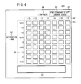
- FIG. 4 is a front elevational view of the third color chart 34c according to the present embodiment.
- the third color chart 34c shown in FIG. 4 comprises 63 color patches 36c made up of different colors which are substantially identical in shape, a string of characters 52 representing "SATURATION ⁇ HUE", a string of characters 54 representing "LIGHTNESS”, a string of characters 56 and a string of numbers 58 for identifying the positions of the color patches 36c along the directions of rows and columns, a color temperature indicating column 60 showing the color temperature of a light source, and a gray patch 62 (solid area), all of which are printed on the print medium 32.
- the color patches 36c are arranged in a matrix having 7 vertical columns and 9 horizontal rows, the color patches being spaced from each other by given intervals.
- the string of characters 56 which serve as identification information, represent a vertical string of characters ranging from +a+b to -a-b positioned in alignment with and at the left of the respective rows of the color patches 36c.
- the string of numbers 58 which also serve as identification information, represent a horizontal string of characters ranging from -15 to +15 positioned in alignment with and at the top of the respective columns of the color patches 36c.
- the color temperature indicating column 60 is disposed in an upper right region of the print medium 32, and shows "FOR STANDARD LIGHT SOURCE 5000K".
- the gray patch 62 is disposed in a lower region of the print medium 32, and is of a rectangular shape which is elongate horizontally on the print medium 32.
- the gray patch 62 is printed in an achromatic color and has a uniform density.
- FIG. 5 is a functional block diagram of the image processing apparatus 16 according to the present embodiment.
- an electronic manuscript is supplied along the directions indicated by outlined solid-line arrows
- colorchart image data is supplied along the directions indicated by the outlined broken-line arrows
- various other data is supplied along the directions indicated by solid-line arrows.
- the main unit 22 of the image processing apparatus 16 includes an I/F 70 for entering an electronic manuscript supplied from the editing apparatus 14, an RIP (Raster Imaging Processor) 72 for converting the PDL format of the electronic manuscript supplied from the I/F 70 into a raster format, a color converter 74 for performing a color converting process on the converted C, M, Y, K values (or R, G, B values) of the electronic manuscript from the RIP 72 in order to produce image data made up of new C, M, Y, K values, a printing machine driver (print controller, print control means) 76 for converting the image data of the new C, M, Y, K values produced by the color converter 74 into a print control signal (ink propulsion control data) that matches the printing process of the printing machine 18, and an I/F 78 for outputting the print control signal generated by the printing machine driver 76 to the printing machine 18.
- RIP Raster Imaging Processor
- the main unit 22 also includes a color manager 80 for managing profiles of different printing machines 18, an image data generator (image generating means) 82 for generating image data to print the first, second, and third color charts 34a, 34b, 34c or a profile color chart, not shown, an I/F 84 for connection to the display device 24, an I/F 86 for connection to the input device 26 including the mouse 28 and the keyboard 30, and an I/F 88 for connection to the colorimeter 20.
- a color manager 80 for managing profiles of different printing machines 18, an image data generator (image generating means) 82 for generating image data to print the first, second, and third color charts 34a, 34b, 34c or a profile color chart, not shown, an I/F 84 for connection to the display device 24, an I/F 86 for connection to the input device 26 including the mouse 28 and the keyboard 30, and an I/F 88 for connection to the colorimeter 20.
- the main unit 22 also includes a storage unit 90 for storing various data supplied from various components of the main unit 22 and for supplying stored data to various components of the main unit 22.
- the storage unit 90 is connected to the RIP 72, the color converter 74, the color manager 80, the image data generator 82, the I/F 84, the I/F 86, and the I/F 88.
- the color converter 74 comprises a target profile processor 92 for converting device-dependent data into device-independent data, and a print profile processor 94 for converting device-independent data into device-dependent data.
- the device-dependent data refer to data defined in terms of C, M, Y, K values, R, G, B values, or the like, for appropriately driving various devices.
- the device-independent data refer to data defined in terms of a display system such as an HSL system, an HSB system, a CIELAB coordinate system, a CIELUV coordinate system, an XYZ system, or the like.
- the image data generator 82 comprises a first data generator (data generator) 96a for generating image data in order to print the first color chart 34a, a second data generator (data generator) 96b for generating image data in order to print the second color chart 34b, a third data generator (data generator) 96c for generating image data in order to print the third color chart 34c, and a profile data generator 98 for generating image data in order to print the profile color chart (not shown).
- the color manager 80 comprises a profile generator 100 for generating profiles for respective printing machines 18, a color chart condition setter (setter) 102 for setting color chart conditions (reference colors and color difference intervals) to be described later, a color comparing condition designator (designator, designating means) 104 for selecting color comparing conditions including not only C, M, Y, K values, color values L*, a*, b*, color temperatures, but also a gamut mapping process, etc., and a patch color converter 106 for converting the color of a color patch 36c which is selected based on color information of a color correction optical filter to be described later.
- a profile generator 100 for generating profiles for respective printing machines 18, a color chart condition setter (setter) 102 for setting color chart conditions (reference colors and color difference intervals) to be described later
- a color comparing condition designator (designator, designating means) 104 for selecting color comparing conditions including not only C, M, Y, K values, color values L*, a*,
- the RIP 72 can perform various image processing processes including an image scaling process depending on the resolution, etc. of the printing machine 18 and a rotating and inverting process depending on a printing format when an electronic manuscript is converted into raster data.
- the printing machine driver 76 generates ink propulsion control data corresponding to ink colors (C, M, Y, K, LC, LM, or W) from C, M, Y, K values.
- the ink propulsion control data are data for appropriately controlling the ink propulsion of the printing machine 18 (ink ejection ON/OFF, ink dot diameters, etc.).
- the printing machine driver 76 may generate the ink propulsion control data according to a known algorithm such as a dither matrix method, an error diffusion method, or the like, although it requires conversion from an 8-bit multiple-gradation image into a low-gradation image such as a binary image.
- the target profile processor 92 or the print profile processor 94 is capable of correcting profiles depending on a print mode of the printing machine 18.
- the print mode refers to various print settings such as the number of nozzles of the print head, the timing (unidirectional/bidirectional) of ink ejection at the time the print head scans, the number of passes, the number and type of inks used on the printing machine 18, an algorithm for generating ink ejection control data, etc.
- the main unit 22 has a controller (not shown) comprising a CPU, etc., for controlling all of the image processing processes described above. More specifically, the controller controls not only operation of various components of the main unit 22, e.g., reading data from and writing data in the storage unit 90, but also transmission of display control signals via the I/F 84 to the display device 24 and acquisition of colorimetric data from the colorimeter 20 via the I/F 88.
- the image processing apparatus 16 is constructed basically as described above.
- the image processing processes or functions described above can be performed according to application software (programs) stored in the storage unit 90 which operates on basic software (operating system).
- the programs may be recorded in a computer-readable recording medium, and may be read from the medium into a computer system and executed thereby.
- the term "computer system" includes an OS and hardware including peripheral devices.
- the computer-readable recording medium comprises a portable storage medium such as a flexible disk, a magnetooptical disk, a ROM, a CD-ROM, or the like, or a storage unit such as a hard disk or the like incorporated into the computer system.
- the computer-readable recording medium also includes a medium for dynamically holding programs for a short period of time, such as a communication line for transmitting programs via a network such as the Internet or the like or via a communication channel such as a telephone line, or a memory for holding programs for a certain period of time such as a volatile memory in a computer system which serves as a server or a client in a network environment.
- a medium for dynamically holding programs for a short period of time such as a communication line for transmitting programs via a network such as the Internet or the like or via a communication channel such as a telephone line, or a memory for holding programs for a certain period of time such as a volatile memory in a computer system which serves as a server or a client in a network environment.
- FIG. 6 is a view showing by way of example a setting screen for setting color comparing conditions for the first, second, and third color charts 34a, 34b, 34c according to the embodiment.
- the setting screen denoted by 110, includes a pull-down menu 112, five radio buttons 114a, 114b, 114c, 114d, 114e, and buttons 116, 118 displaying "SETTING", “CANCEL”, respectively, which are successively arranged from an upper portion to a lower portion of the setting screen 110.
- the setting screen 110 also includes a string of characters "MAPPING PROCESS" on the right side of the pull-down menu 112.
- the setting screen 110 displays a selection column, not shown, beneath the pull-down menu 112.
- the setting screen 110 also includes letters "CMYK VALUES”, “L*a*b*”, “L*C*H*/COLOR TEMPERATURE”, “L*/C*H*(5000K)”, “MAPPING PROCESS” displayed on the right sides of the respective radio buttons 114a, 114b, 114c, 114d, 114e.
- the printing system 10 is basically constructed as described above. Operation of the printing system 10 will be described below.
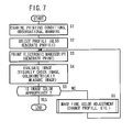
- FIG. 7 is a flowchart of a sequence for producing a print 34 of appropriate color with the printing system 10 according to the embodiment. Operation of the printing system 10 will be described in detail below with reference to FIG. 1 .
- the operator examines printing conditions and observational manners of a print 34 to be produced (step S1).
- the printing conditions refer to the type of the printing machine 18 to be used to produce the print 34, the type of the print medium 32, and the print mode described above.
- the observational manners refer to the attributes (type, spectral data) of a light source DS serving as an observational light source for the print 34 and also the type of the image on the print 34 to be observed.
- the type of the image may represent a reflective image (an image generated using a reflective light source as a main light source), a transmissive image (an image generated using a transmissive light source as a main light source), or a mixed image (an image generated using reflective and transmissive light sources as main light sources).
- step S2 the operator selects a profile suitable for the printing machine 18 (step S2). Normally, a target profile or a print profile is stored in the storage unit 90. If a profile suitable for the printing machine 18 is not registered, i.e., is not stored in the storage unit 90, then a print profile can be generated separately.
- step S3 an electronic manuscript is printed using the printing machine 18, thereby producing a color print 34 (step S3).
- the print 34 may be laminated by a laminating apparatus, not shown, in order to provide a protective film over the image surface of the print 34.
- the color image of the print 34 can thus be protected for better abrasion resistance and toughness.
- the operator evaluates the color of the color image of the print 34 (step S4), and determines whether or not the color of the image is appropriate (step S5).
- the operator may evaluate the color of the image so as to determine whether desired hues are obtained or not, either by visually checking the image based on the observation of an overall or partial appearance of the image, or by obtaining a colorimetric value of a certain area of the print 34 with the colorimeter 20 and thereby determining whether or not the obtained colorimetric value falls within a desired range.
- the operator changes the profile or the like in order to make fine adjustments of the color of the image (step S6). More specifically, the operator may reset the profile or regenerate a profile or may make a fine adjustment of the profile, (i.e., correction of the presently set profile), or may correct print data of the electronic manuscript.
- step S3 An image processing sequence of the image processing apparatus 16 for printing an electronic manuscript (step S3) will be described in detail below with reference to FIG. 5 .
- the electronic manuscript is converted into 8-bit C, M, Y, K raster data (device-dependent image data) by the RIP 72.
- the 8-bit C, M, Y, K raster data are then converted into L*, a*, b* data (device-independent image data) by the target profile processor 92.
- the L*, a*, b* data are then converted into C, M, Y, K value data (device-dependent image data) by the print profile processor 94.
- the C, M, Y, K value data are then converted into a print control signal (ink ejection control data) by the printing machine driver 76.
- the print control signal is supplied from the printing machine driver 76 via the I/F 78 to the printing machine 18. If necessary, the C, M, Y, K raster image data converted by the RIP 72 are temporarily stored in the storage unit 90. Thereafter, the printing machine 18 produces a desired print 34 based on the print control signal.
- target profiles and print profiles corresponding to a plurality of set conditions have been stored in the storage unit 90, a target profile and a print profile are selectively supplied to the target profile processor 92 and the print profile processor 94, respectively, depending on various preset conditions. If the profiles are appropriately corrected in view of the print mode of the printing machine 18, then a more appropriate color conversion process can be performed.
- step S2 An image processing sequence of the image processing apparatus 16 for generating a profile (step S2) will be described in detail below with reference to FIG. 5 .
- Image data generated by the profile data generator 98 based on given C, M, Y, K value data stored in the storage unit 90, are supplied via a path R1 shown in FIG. 5 to the printing machine driver 76, and the image data are supplied to the printing machine 18 in the same manner as printing an electronic manuscript.
- Color patches of a profile color chart (not shown) thus produced are measured by the colorimeter 20, which is connected to the image processing apparatus 16, thereby producing color values L*, a*, b*.
- the color value data are temporarily stored in the storage unit 90.
- a three-dimensional to fourdimensional conversion LUT (a portion of the data of the print profile) can be generated.
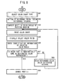
- FIG. 8 is a flowchart illustrative of a process of finely adjusting a color using the first, second, and third color charts 34a, 34b, 34c (step S6), i.e., FIG. 8 is a flowchart of a process of adjusting a designated color.
- step S61 the operator selects a type of color chart. Details of the selection of a type of color chart will be described later. It is assumed that the first color chart 34a is selected and L*, a*, b* are selected as color comparing conditions.
- a reference color and a color difference interval of the first color chart 34a are initialized (step S62). These values can freely be set by the color chart condition setter 102 (see FIG. 5 ).
- color values corresponding to the color number of a color sample of color chips or the like may be acquired and used as the initial values of the reference color (L* 0 , a* 0 , b* 0 ).
- the color values may be acquired by measuring the actual color sample with the colorimeter 20.
- color values associated with color numbers may be stored in advance in the storage unit 90, and color values corresponding to a designated color number may be read from the storage unit 90.
- the reference color and the color difference interval may be initialized by selecting values with a GUI controller such as a color wheel.
- the color difference interval ( ⁇ L*, ⁇ a*, ⁇ b*) may be initialized to appropriate values, which have been empirically established in color adjustment operations.
- the corrective amounts L*(diff), a*(diff), b*(diff) are added to the designed values of the colors for thereby correcting a slight shift of a print color in order to achieve an increase in the color reproduction accuracy.
- the print 34 may incorporate the first color chart 34a to be printed subsequently.
- the first color chart 34a is printed (step S64).
- the color patches 36a are arranged in a two-dimensional matrix on the first color chart 34a such that the values a* change vertically and the values b* change horizontally at given color difference intervals ( ⁇ a*, ⁇ b*).
- color values corresponding to the respective color patches 36a may be determined according to the following equations (4) through (6):
- FIG. 9 is a diagram showing a presentation area of the first color chart 34a according to the present embodiment.
- the presentation area refers to a color area formed by the color patches 36a of the first color chart 34a.
- a hexagonal area formed on the a* - b* plane, with L* being fixed, represents a gamut 130 of the printing machine 18. If the colors of the color patches 36a are plotted according to the above equations (5) and (6), for example, then the plotted points are disposed at equal intervals.
- the presentation area 132 corresponds to a rectangular area formed by four points (a* 0 + 3 ⁇ a*, b* 0 + 3 ⁇ b*), (a* 0 + 3 ⁇ a*, b* 0 - 3 ⁇ b*), (a* 0 - 3 ⁇ a*, b* 0 + 3 ⁇ b*) , (a* 0 - 3 ⁇ a*, b* 0 - 3 ⁇ b*).
- the first data generator 96a (see FIG. 5 ) generates image data such that the color differences between adjacent color patches 36a are at a substantially equal interval.
- the reference color and the color difference interval can be provided by reading data that are preset by the color chart condition setter 102 and stored in the storage unit 90.
- the image data generated by the first data generator 96a are supplied via a path R2 to the print profile processor 94 as shown in FIG. 3 .
- the image data are supplied from the print profile processor 94 to the printing machine 18 in the same manner as when an electronic manuscript is printed.
- the color patches 36a of the first color chart 34a (see FIG. 2 ) substantially reproduce the pre-designed color (L*, a*, b*).
- the image data used to print the first color chart 34a are not limited to raster image data such as TIFF or bitmap data, but may be PDL-format image data such as PDF or PostScript (registered trademark) data.
- the second and third color charts 34b, 34c are the same as the first color chart 34a except that their image data are generated by the second and third data generators 96b, 96c, respectively.
- the operator selects one of the color patches 36a of the printed first color chart 34a (step S65). Specifically, the operator visually compares a color sample representing a designated color serving as a target (e.g., a color chip or a color displayed by the display device 24) with the first color chart 34a, and selects one of the color patches 36a whose color is closest to the designated color.
- a target e.g., a color chip or a color displayed by the display device 24
- the operator visually recognizes change of the colors of the color patches 36a at substantially equal intervals when the operator visually observes the first color chart 34a.
- the operator can easily select a color patch 36a whose color is closest to the designated color.
- the operator enters the identification information of the selected color patch 36a (step S66). Specifically, the operator enters numerical values (see FIG. 2 ) represented by the row number 38 and the column number 40 which correspond to the position of the selected color patch 36a, using the input device 26 through an unillustrated setting screen.
- the operator determines whether a color that is substantially the same as the designated color has been reproduced by the selected color patch 36a (step S67). If the operator judges that a color that is substantially the same as the designated color has not been reproduced, but there is still a possibility of selection, then the operator resets a next reference color and color difference interval (step S68). Thereafter, another first color chart 34a is printed based on the reset reference color and color difference interval.
- step S64 through S68 The above process is repeated until a color that is identical to the designated color is reproduced on the first color chart 34a. Subsequently, the profile is updated (step S69), and the process of adjusting the designated color is completed.
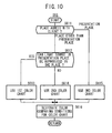
- FIG. 10 is a flowchart of a process (step S61) of selecting one of the types of the first, second, and third color charts 34a, 34b, 34c.
- a place which has been agreed between the operator and the client is confirmed (step S611).
- the agreement is reached between the operator and the client as a result of an actual visual check of a color sample of color chips or the like.
- the agreed place is not the presentation place, but is a printing site or a business place
- it is confirmed whether or not the observational environment (the light source DS) for the presentation place of the print 34 can be reproduced in the printing site or the business place (step S612). If the light source DS can be reproduced, then the first color chart 34a is used (step S613). If the light source DS cannot be reproduced, then the second color chart 34b is used (step S614).
- the agreed place is the presentation place (i.e., the environment under the light source DS)
- the third color chart 34c is used (step S615).
- the operator selects one of the types of the color charts using one of the radio buttons 114a through 114e in the setting screen 110 shown in FIG. 6 .
- the operator selects the radio button 114b.
- the operator selects the radio button 114c.
- the operator selects the radio button 114d.
- CMYK VALUES a color chart, not shown, in which the differences between the pixel values of the C, M, Y, K values of adjacent color patches are of equal intervals, is printed. If “MAPPING PROCESS” indicated by the radio button 114e is selected and if the designated color is a color outside the gamut 130, then a color chart (not shown) for comparing colors produced by a plurality of mapping processes in order to replace the designate color with a color within the gamut 130, is printed.
- mapping processes include "LIGHTNESS MATCHING”, “LIGHTNESS PRIORITY”, “SATURATION MATCHING”, “SATURATION PRIORITY”, “MINIMUM DISTANCE”, AND “IMPRESSION MATCHING”.
- a gamut mapping for printing one of various color charts (either one of the color charts corresponding to the radio buttons 114a through 114d in FIG. 6 ) can be selected from the pull-down menu 112.
- the color comparing condition designator 104 designates a type of color chart and color comparing conditions via the setting screen 110.
- specific processes for selecting one of the color patches 36a, 36b, 36c from the first, second, and third color charts 34a, 34b, 34c will be described in detail below.
- the color temperature of the observational light source at the printing site is checked. For example, it is assumed that the color temperature is 6500K.
- a color that is closest to the designated color is selected from the 9 color patches 36b which belong to the vertical column indicated by "6500K” in the string of characters 50 shown in FIG. 3 . It is assumed that a color patch 36b at "0" (on the string of numbers 46) of "LIGHTNESS" (the string of characters 42) is selected.
- the color temperature of the light source DS in the presentation place is "2800K"
- the color temperature of the light source DS in the presentation place is "2800K”
- the color may be finely adjusted such that the color (whose lightness is “0") corresponding to the color temperature of 2800K under the light source DS in the presentation place is associated with the designated color.
- the patch color converter 106 see FIG.
- the appearance of the color in the printing site (under the light source PS) and the appearance of the color in the presentation place (under the light source DS) can be confirmed by way of visual inspection of one color chart (second color chart 34b). It is appropriate to select the second color chart 34b if change in the appearance of the printed color under different observational light sources DS and the tendency of such change need to be recognized by the operator.
- FIG. 11 is a perspective view illustrative of a process of quantifying the difference between the appearances of colors of images with the observational light source DS and the standard light source (D50), using color correction filters 134 (color correction optical filters).
- the third color chart 34c has its colors adjusted to provide a suitable gradation under the observational light source (D50 light source). If the light source DS in the presentation place is not the D50 light source, then the appearance of colors is shifted.
- D50 light source observational light source
- the observer Obs i.e., the operator, confirms the colors of the image of the third color chart 34c through a color correction filter 134a, which is held by the observer Obs at a position between the eyes of the observer Obs and the third color chart 34c.
- the observer Obs judges that the third color chart 34c does not have a color patch 36c whose color is substantially the same as the designated color, then the observer Obs replaces the color correction filter 134a with another color correction filter 134 having a different frequency pass band, and similarly observes the third color chart 34c.
- the observer Obs repeatedly uses various color correction filters 134 and observes the third color chart 34c through those color correction filters 134 until the observer Obs finds and selects a color correction filter 134 through which the observer Obs observes the most appropriate colors of the third color chart 34c.
- the observer Obs may select not only one color correction filter 134, but also two or more color correction filters 134 having identical or different frequency pass bands, for use in superposition.
- the color correction filters 134 perform a function to freely adjust the range of the presentation area 132 (see FIG. 9 ) of the color patches 36c visually recognized by the observer Obs. For example, if the color difference corresponding to one-half of the color difference interval is shifted, then a color between adjacent color patches 36c can be simulated. If the color difference is shifted greatly, then the range of the presentation area 132 can be moved without increasing the number of color patches 36c and the color difference interval thereof.
- gray patch 62 (see FIG. 4 ) in the lower portion of the third color chart 34c and select a color correction filter 134 through which the color of the gray patch 62 can be visually recognized as a more neutral gray. This is because the human eye is more sensitive to color differences between achromatic colors than between chromatic colors.
- color correction based on such an appropriate color correction filter 134 can be reflected in the adjusted color.
- color values such as L*, a*, b*, or X, Y, Z, or the like under the light source DS with respect to spectral data of the standard light source (D50 light source).
- the first, second, and third color charts 34a, 34b, 34c have been described above. According to the present invention, various color charts for use in different situations and uses can be printed. Modifications of the first color chart 34a will be described below.
- FIGS. 12A through 12D shows a first modification of the first color chart 34a.
- the first color chart 34a is different from the first color chart 34a according to the above embodiment as to the sequence of color patches 36a.
- the color patches 36a are arranged on the flat print medium 32 to keep the colors of adjacent ones of the color patches 36a continuous while changing the three-dimensional variables L*, a*, b*.
- FIGS. 12A and 12B are diagrams showing the layouts of the color patches 36a on the first color chart 34a. Though the color patches 36a are actually spaced apart in the manner shown in FIG. 2 , they are shown as being closely positioned without any gaps therebetween for illustrative purposes.
- the characters shown in each of the cells e.g., "A-4" in the cell at the upper left corner of the matrix shown in FIG. 12A , represent the attributes of the color of the color patch 36a corresponding to the cell.
- FIGS. 12C and 12D are diagrams showing the design values of the colors of the respective color patches 36a.
- the design values represent the values of deviations (L*(dev), a*(dev), b*(dev)) from the reference color (L*, a*,b*).
- Characters 136 (A through D) shown in FIG. 12C correspond to alphabetical letters of the characters in the cells shown in FIGS. 12A and 12B , e.g., "A” shown in FIG. 12C corresponds to "A” of the characters "A-4" in the cell at the upper left corner of the matrix shown in FIG. 12A .
- Characters 138 (1 through 9) shown in FIG. 12D correspond to numbers of the characters in the cells shown in FIGS. 12A and 12B , e.g., "4" shown in FIG. 12D corresponds to "4" of the characters "A-4" in the cell at the upper left corner of the matrix shown in FIG. 12A .
- FIG. 12A A specific example of the sequence of colors shown in FIG. 12A will be described in detail below with reference to FIGS. 12C and 12D .
- the matrix of color patches 36a has its colors defined according to the sequence "A-1", “A-2”, ⁇ , “A-9", “B-1”, “B-2”, ⁇ , “D-8", “D-9” (see the directions of arrows extending from cells to cells).
- the cells whose characters 136 represent "A” are localized in an upper left area (a small matrix of 3 ⁇ 3) of the matrix of 6 ⁇ 6.
- the cells whose characters 136 represent "B” are localized in an upper right area (a small matrix of 3 ⁇ 3) of the matrix of 6 ⁇ 6.
- the deviation L*(dev) of the lightness in those cells represents ⁇ L*.
- the colors are arranged in a zigzag pattern such that a* and b* are gradually changed while the lightness is fixed (L*- ⁇ L*).
- the pattern of the deviations of a* and b* (two-dimensional variables) is used as one period, and the deviation of L* (one-dimensional variable) is gradually changed in each period to keep the colors of adjacent color patches 36a continuous.
- the first modification is preferable as it allows the operator to select a color closest to the designated color from the color patches 36a more easily.
- the colors whose characters 136 represent "A”, “B”, “C”, and “D” may be arranged in sequences along one direction.
- FIGS. 13A through 13C show a second modification of the first color chart 34a.
- the second modification is different from the first modification as to the sequence of the colors of the color patches 36a.
- the definition of the cells and characters associated therewith shown in FIGS. 13A through 13C are identical to those shown in FIGS. 12A, 12C, and 12D and will not be described in detail below.
- FIG. 13A A specific example of the sequence of colors shown in FIG. 13A will be described in detail below with reference to FIGS. 13B and 13C .
- the matrix of color patches 36a has its colors defined according to the sequence "A-1", “A-2", ⁇ , “A-4", “B-1", “B-2”, ⁇ , “I-3”, “I-4" (see the directions of arrows extending from cells to cells).
- the cells whose characters 136 represent "A” are localized in an upper left area (a small matrix of 2 ⁇ 2) of the matrix of 6 ⁇ 6.
- the deviations (a*(dev), L*(dev)) represent ( ⁇ a*, ⁇ L*).
- the characters 138 ranging from “1” through “4" are associated with the deviation b*(dev) for the cells according to the rules shown in FIGS. 12C , and colors associated with the cells are accordingly determined. In other words, the colors are arranged in a zigzag pattern such that b* is gradually changed while a* and L* are fixed (a*+ ⁇ a*, L*+ ⁇ L*) .
- the cells whose characters 136 represent "B” are localized in an upper central area (a small matrix of 2 ⁇ 2) of the matrix of 6 ⁇ 6.
- the deviations (a*(dev), L*(dev)) in those cells represent (0, ⁇ L*).
- the colors are arranged in a zigzag pattern such that b* is gradually changed while a* and L* are fixed (a*, L*+ ⁇ L*).
- the pattern of the deviation of b* (one-dimensional variable) is used as one period, and the deviations of L*, a* (two-dimensional variables) are gradually changed in each period to keep the colors of adjacent color patches 36a continuous.
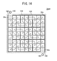
- FIG. 14 shows a third modification of the first color chart 34a.
- a first color chart 34aA according to the third modification is different from the above embodiment and the first and second modifications as to the number of color patches 36a and plotting specifications.
- the first color chart 34aA includes 81 color patches 36a.
- the color patches 36a have their colors defined in a predetermined sequence such that the colors of the color patches 36a are gradually changed.
- a color patch 36s corresponding to a starting color is positioned at an upper left corner of the matrix and a color patch 36e corresponding to an ending color is positioned at a lower right corner of the matrix.
- the first color chart 34aA also includes arrows 140, 142 printed thereon which are oriented to the color patches 36s, 36e, respectively.
- An observational route 144 which corresponds to a predefined sequence of colors, is established along the broken lines, and has a zigzag pattern as is the case with the first and second modifications (see FIGS. 12A and 13A ).
- Guide lines 146 which extend according to predetermined rules are disposed along some of the color patches 36a.
- the guide lines 146 allow the operator to observe the color patches 36a along the observational route 144.
- the guide lines 146 include a gap 148 above the color patch 36s at the starting color and a gap 150 beneath the color path 36e at the ending color. As the guide lines 146 with the gaps 148, 150 resemble a maze with an entrance and an exit, the operator can visually recognize the observational route 144 with intuition.
- the guide lines 146 with the gaps 148, 150 serve to guide the operator to follow the observational route 144 for the color patches 36a.
- the observational route 144 may actually be printed as part of the first color chart 34aA if it will not adversely affect the process of comparing colors.
- FIG. 15 shows a fourth modification of the first color chart 34a.
- a first color chart 34aB according to the fourth modification is different from the above embodiment and the first through third modifications as to portions of the background color.
- the first color chart 34aB comprises four color charts printed on a print medium 32, i.e., a color chart 200a in an upper left area thereof, a color chart 200b in an upper right area thereof, a color chart 200c in a lower left area thereof, and a color chart 200d in a lower right area thereof.
- the color chart 200a includes 25 color patches 36a arranged in a matrix of 5 rows and 5 columns, row numbers 38, and column numbers 40.
- the row numbers 38, the column numbers 40, and the colors of the color patches 36a are the same as those of the first color chart 34a shown in FIG. 2 , and will not be described in detail below.
- the color chart 200a has a background that is not colored at all, and also includes a letter 202a representing "A" printed at a lower right corner of the color chart 200a.
- the color chart 200b is substantially identical in layout to the color chart 200a except that the color chart 200b has a background that is colored in a pale color and includes a letter 202b representing "B" printed at a lower right corner of the color chart 200b.
- the color chart 200c is substantially identical in layout to the color chart 200b except that the color chart 200c has a background that is colored in a similar color darker than the background of the color chart 200b and includes a letter 202c representing "C" printed at a lower right corner of the color chart 200c.
- the color chart 200d is substantially identical in layout to the color chart 200c except that the color chart 200d has a background that is colored in a similar color darker than the background of the color chart 200c and includes a letter 202d representing "D" printed at a lower right corner of the color chart 200d.
- the backgrounds of the color charts 200a, 200b, 200c, 200d are colored in similar colors of different densities.
- the background colors can freely be set via a setting screen, not shown.
- the background colors should preferably be set based on R, G, B values, C, M, Y, K values, L*, a*, b* values, or the like.
- the designated color can be adjusted in view of a change of spectral sensitivity characteristics of vision depending on the background color (so-called "chromatic adaptation").
- color chart conditions (reference colors and color difference intervals) are automatically set by the color chart condition setter 102.
- specification changes may be made in view of the preferences of the operator or client as to color selections.
- a setting screen may include text boxes which display recommended values set by the color chart condition setter 102.
- the operator may change the displayed values and set the changed values using the keyboard 28, etc.
- the operator may freely change the number of color patches 36a, 36b, 36c.
- the printing machine 18 comprises an inkjet printing apparatus.
- the printing machine 18 may comprise an electrophotographic apparatus, a thermosensitive apparatus, or the like.
Landscapes
- Engineering & Computer Science (AREA)
- Multimedia (AREA)
- Signal Processing (AREA)
- Color Image Communication Systems (AREA)
- Facsimile Image Signal Circuits (AREA)
- Image Processing (AREA)
- Dot-Matrix Printers And Others (AREA)
- Color, Gradation (AREA)
Abstract
Color comparing conditions can include a type of observational light source.
Description
- The present invention relates to a color selecting method, an image processing method, an image processing apparatus, and a recording medium for printing a color chart having a plurality of color patches with a printing machine, and selecting one of the color patches of the color chart which is closest to a designated color.
- With significant advances in inkjet technology in recent years, it has become possible for inkjet printers to produce large color prints of high quality at high speeds. Inkjet printers are not only popular for private or home use, but nowadays also are widely used in commercial applications. Inkjet printers make it possible to print on POP (Point Of Purchase) posters, wall posters, large-size mediums such as outdoor advertisements and billboards, roll mediums, and thick hard mediums.
- There are a wide variety of print mediums (hereinafter also referred to as "mediums") available for use in prints to meet various commercial demands. For example, such print mediums include paper mediums such as synthetic paper, thick paper, aluminum-evaporated paper, etc., resin mediums such as those made of vinyl chloride, PET, etc., and tarpaulin paper made of woven fiber cloth with synthetic resin films applied to both surfaces thereof.
- Since prints for use as advertisements (print mediums which have been printed) are expected to be effective to arouse consumer's motivation to buy advertised products through visual sensations of the consumer, the color finish of such prints is of particular importance. Heretofore, there have been disclosed various color matching technologies such as a method of generating an ICC (International Color Consortium) profile, a method of adjusting a designated color, etc. as a print color managing means. Such color matching technologies are applicable not only to inkjet printers but also to all types of digital printers, including those based on electrophotographic and thermosensitive principles, together with their peripheral devices across the board.
- The method of adjusting a designated color referred to above comprises a method of making fine color adjustments of an area of interest in an image in order to bring the color into substantial conformity with a given color (designated color) designated by a color sample of color chips, while maintaining the color balance of the image as a whole. There have been disclosed various methods of adjusting a designated color.
- A method of selecting a plurality of candidate colors may be carried out by gradually changing the values of variables that can be controlled for print. Examples of such variables include device-depending data such as C, M, Y, K data, R, B, G data, etc.
- For example, Japanese Laid-Open Patent Publication No.
2000-217007 2000-217007 FIGS. 4 and5 of Japanese Laid-Open Patent Publication No.2000-217007 - In order to print a color closest to a designated color using a printing machine where the device-dependent data represent C, M, Y, K, it is necessary to determine optimum values for four variables of C, M, Y, K.
- If a designated color falls outside the range of the gamut of a printing machine, it is physically impossible to reproduce the designated color. In such a case, the designated color is replaced with a certain color (i.e., a color closest to the designated color) within the range of the gamut, and a gamut mapping process is carried out taking into account the color balance of the overall image. To this end, it is necessary to select an optimum gamut mapping process (hereinafter also referred to as "mapping process").
- If an observational environment in which a print is formed and an observational environment in which the print is displayed are different from each other, then the difference between the observational environments have to be taken into consideration. Specifically, the types of observational light sources, the types of background colors, etc. have to be considered as variable factors, and the colors of color patches to be printed on a color chart need to be appropriately selected. In addition, selected colors may be different depending on color preference of each person.
- Thus, the manner in which colors are presented varies depending on controllable variables (device-dependent data or mapping processes), and the manner in which colors are seen varies depending on the observational environment. For printing a color chart taking all the above items into account, the number of color patches to be printed needs to be increased because it is necessary to widen the color presentation range for increasing color choices and it is necessary to attain color resolution for more strict color selection.
- For example, if the values on the axes of L*, a*, b* are to be independently selectable in 10 stages, then 103 = 1000 color patches are required. As the number of color patches increases, the burden on the operator for selecting colors also increases and the overall size of a color chart including those color patches becomes larger. Therefore, the efficiency with which the operator works is lowered, making it difficult for the operator to select desired colors.
- It is an object of the present invention to provide a color selecting method, an image processing method, an image processing apparatus, and a recording medium which allow the operator to select colors efficiently and easily without an excessive increase in the number of color patches on a color chart.
- According to the present invention, there is provided a color selecting method of printing a color chart having a plurality of color patches with a printing machine and selecting one of the color patches whose color is closest to a designated color from the color chart.
- The color selecting method comprises the steps of designating a color comparing condition for the color chart, and generating image data to print the color chart in which color patches having colors corresponding respectively to different variables of the designated color comparing conditions are disposed adjacent to each other.
- The color comparing condition for the color chart refers to various conditions for comparing the colors of the color patches on the color chart to see if the colors are acceptable or not, and includes not only variables such as C, M, Y, K values, color values L*, a*, b*, etc., but also a type of observational light source, a gamut mapping process, etc. The type of observational light source includes not only the general name of a light source such as a tungsten lamp, a fluorescent lamp (F2, F6, F7, or the like), daylight D65, or the like, but also various data such as a color temperature, a spectral radiance distribution, etc.
- With the above arrangement, appropriate color comparing conditions can be designated depending on the situation in which the color selecting method is performed, thereby allowing the operator to select a color efficiently and easily.
- Preferably, the color comparing condition includes the type of observational light source. The operator is thus able to select a color which is different under a different observational light source.
- Preferably, the color comparing condition includes a background color. The operator is thus able to select a color in view of a change of spectral sensitivity characteristics of vision depending on the background color (so-called "chromatic adaptation).
- Preferably, the color comparing condition includes lightness, saturation, and hue.
- Preferably, the color comparing condition includes a gamut mapping process. The operator is thus able to select a color within the range of the gamut efficiently in a manner acceptable to the operator even if the designated color is a color outside the gamut.
- Preferably, the step of generating image data generates the image data such that the color patches having colors gradually changed are disposed in a zigzag pattern. Therefore, the operator can continuously track down the colors of the color patches as they change and can easily select a color patch whose color is closest to the designated color.
- Preferably, the step of generating image data generates the image data so as to include a guide line for observing the color patches along a route according to the zigzag pattern. The guide line allows the operator to easily and efficiently track down the colors of the color patches as they change.
- Preferably, the one of the color patches whose color is closest to the designated color is selected under a predetermined observational light source from those of the color patches in the color chart which correspond to the type of the predetermined observational light source.
- Preferably, the color selecting method further comprises the steps of printing the color chart after a color conversion thereof depending on a predetermined light source has been performed, and observing the color chart through color correction optical filters under an observational light source different from the predetermined light source, and selecting the one of the color patches whose color is closest to the designated color and selecting one of the color correction optical filters. The appearance of the colors of the color patches can thus freely be adjusted.
- Preferably, the step of selecting one of the color correction optical filters selects the one of the color correction optical filters by evaluating the saturation of an achromatic solid area on the color chart, the achromatic solid area being provided separately from the color patches.
- According to the present invention, there is also provided an image processing method comprising the steps of designating a color comparing condition for a color chart having a plurality of color patches, generating image data to print the color chart in which color patches having colors corresponding respectively to different variables of the designated color comparing condition are disposed adjacent to each other, printing the color chart with a printing machine based on the generated image data, entering color values of a designated color, and converting colors of a print to be produced by the printing machine, based on color values of one of the color patches whose color is selected as a color closest to the designated color from the printed color chart and based on the entered color values of the designated color.
- According to the present invention, there is also provided an image processing method using the color selecting method described above, comprising the steps of converting color values of the selected one of the color patches whose color is closest to the designated color into color values under the observational light source different from the predetermined light source, based on color information of the selected one of the color correction optical filters, entering color values of the designated color, and converting colors of a print to be produced by the printing machine, based on the color values under the observational light source different from the predetermined light source and based on the entered color values of the designated color.
- According to the present invention, there is further provided an image processing apparatus comprising a designator for designating a color comparing condition for a color chart having a plurality of color patches, a data generator for generating image data to print the color chart in which color patches having colors corresponding respectively to different variables of the color comparing condition designated by the designator are disposed adjacent to each other, a print controller for controlling a printing machine to print the color chart based on the image data generated by the data generator, and a color converter for converting colors of a print to be produced by the printing machine, based on color values of one of the color patches whose color is selected as a color closest to the designated color from the printed color chart and based on the entered color values of the designated color.
- According to the present invention, there is further provided an image processing apparatus comprising a patch color converter for converting color values of the one of the color patches whose color is closest to the designated color and which is selected by the color selecting method described above, into color values under the predetermined light source, based on color information of the selected one of the color correction optical filters, and a color converter for converting colors of a print to be produced by the printing machine, based on the color values under the observational light source different from the predetermined light source which are converted by the patch color converter and based on the entered color values of the designated color.
- According to the present invention, there is also provided a recording medium storing a program for enabling a computer to perform the functions of designating a color comparing condition for a color chart, generating image data to print the color chart in which color patches having colors corresponding respectively to different variables of the designated color comparing condition are disposed adjacent to each other, and printing the color chart based on the image data.
- With the color selecting method, the image processing method, the image processing apparatus, and the recording medium according to the present invention, color comparing conditions for the color chart are designated, and image data are generated to print the color chart in which color patches having colors corresponding respectively to different variables of the designated color comparing conditions are disposed adjacent to each other. Consequently, appropriate color comparing conditions can be designated depending on the situation in which the color selecting method is carried out, thereby allowing the operator to select a color efficiently and easily.
- The above and other objects, features, and advantages of the present invention will become more apparent from the following description when taken in conjunction with the accompanying drawings in which preferred embodiments of the present invention are shown by way of illustrative example.
-
-
FIG. 1 is a perspective view of a printing system incorporating an image processing apparatus according to an embodiment of the present invention; -
FIG. 2 is a front elevational view of a first color chart according to the embodiment; -
FIG. 3 is a front elevational view of a second color chart according to the embodiment; -
FIG. 4 is a front elevational view of a third color chart according to the embodiment; -
FIG. 5 is a functional block diagram of the image processing apparatus according to the embodiment; -
FIG. 6 is a view showing by way of example a setting screen for setting color chart color comparing conditions according to the embodiment; -
FIG. 7 is a flowchart of a sequence for producing a print of appropriate color with the printing system according to the embodiment; -
FIG. 8 is a flowchart of a process of adjusting a designated color using the color chart according to the embodiment; -
FIG. 9 is a diagram showing a presentation area formed by a first color chart according to the embodiment; -
FIG. 10 is a flowchart of a process of selecting one of the types of color charts according to the embodiment; -
FIG. 11 is a perspective view illustrative of a process of quantifying the difference between the appearances of images with an observational light source and a standard light source, using color correction filters; -
FIGS. 12A through 12D are front elevational views of a first color chart according to a first modification of the embodiment; -
FIGS. 13A through 13C are front elevational views of a first color chart according to a second modification of the embodiment; -
FIG. 14 is a front elevational view of a first color chart according to a third modification of the embodiment; and -
FIG. 15 is a front elevational view of a first color chart according to a fourth modification of the embodiment. - Color selecting methods according to preferred embodiments of the present invention in relation to an image processing apparatus and a printing system for carrying out the color selecting methods, will be described in detail below with reference to the accompanying drawings.
-
FIG. 1 shows in perspective aprinting system 10 incorporating animage processing apparatus 16 according to an embodiment of the present invention. - As shown in
FIG. 1 , theprinting system 10 basically comprises aLAN 12, anediting apparatus 14, animage processing apparatus 16, aprinting machine 18, and acolorimeter 20. - The
LAN 12 makes up a network constructed according to communication standards such as Ethernet (registered trademark) or the like. Theediting apparatus 14 and theimage processing apparatus 16 are connected to each other through theLAN 12 by a wired or wireless link. - The
editing apparatus 14 is capable of editing the arrangement of color images made up of characters, figures, pictures, photos, etc. on each of pages to be printed. Theediting apparatus 14 generates electronic manuscripts in a page description language (hereinafter referred to as "PDL"), e.g., 8-bit image data in color channels of four colors (C, M, Y, K) or three colors (R, G, B). - PDL refers to a language, which is descriptive of image information including format information, positional information, color information (including density information), etc., of characters, figures, etc., in a "page" that serves as an output unit for printing, displaying, or the like. Known types of PDL include PDF (Portable Document Format according to ISO32000-1:2008 PostScript (registered trademark) of Adobe Systems, and XPS (XML Paper Specification).
- A color scanner, not shown, is connected to the
editing apparatus 14. The color scanner is capable of optically reading a color original set in position. Therefore, theediting apparatus 14 can acquire color image data from the color scanner, based on the color original read thereby, as the image data of an electronic manuscript. - The
image processing apparatus 16 converts the color image data of an electronic manuscript described by PDL and acquired from theediting apparatus 14 into raster image data (e.g., a type of bitmap image data), performs a desired image processing process, e.g., a color conversion process, an image scaling process, an image arranging process, etc. on the raster image data, converts the processed raster image data into a print control signal that matches the printing process of theprinting machine 18, and sends the print control signal to theprinting machine 18. - The
image processing apparatus 16 comprises amain unit 22 including a CPU, a memory, etc., adisplay device 24 for displaying color images, and aninput device 26 serving as an input unit and including akeyboard 28 and amouse 30. Thecolorimeter 20 is connected to themain unit 22 of theimage processing apparatus 16. - The
printing machine 18 comprises an inkjet printing apparatus for producing a color image based on a combination of standard inks of colors C, M, Y, K (process colors), together with optional inks of light colors such as LC, LM, etc. and W (white). Theprinting machine 18 controls the propulsion of inks onto a print medium 32 (rolled nonprinted medium inFIG. 1 ) based on a print control signal received from an external apparatus, e.g., theimage processing apparatus 16, in order to print a color image on theprint medium 32, thereby producing aprint 34 which may include afirst color chart 34a, asecond color chart 34b, and athird color chart 34c as types of theprint 34. - The
print medium 32 may comprise a paper medium such as synthetic paper, thick paper, aluminum-evaporated paper, or the like, a resin medium such as vinyl chloride, PET, or the like, or tarpaulin paper, or the like. - The
colorimeter 20 measures the color values of an object to be measured. The color values refer to not only tristimulus values X, Y, Z, the coordinates L*, a*, b* of a uniform color space, etc., but also a distribution of optical material characteristic values (hereinafter referred to as "spectral data") with respect to wavelengths, e.g. a spectral radiance distribution, a spectral sensitivity distribution, a spectral reflectivity, or a spectral transmittance. - The
print 34 thus produced is exhibited in a desired location under a light source DS (another observational light source) whose spectral radiance distribution is different from a light source PS (prescribed observational light source) of theprinting system 10, and observed by an observer. -
FIG. 2 is a front elevational view of thefirst color chart 34a according to the present embodiment. - The
first color chart 34a shown inFIG. 2 comprises 49color patches 36a made up of different colors which are substantially identical in shape, androw numbers 38 andcolumn numbers 40 for identifying the positions of thecolor patches 36a along the directions of rows and columns, all of which are printed on theprint medium 32. - The
color patches 36a are arranged in a matrix having 7 vertical columns and 7 horizontal rows, thecolor patches 36a being spaced from each other by given intervals. Colors of therespective color patches 36a are set to given values in a range of signal levels of C, M, Y, K values (a percentage range from 0% to 100% or a 8-bit gradation range from 0 to 255). - The row numbers 38, which serve as identification information, represent a vertical string of characters ranging from (+3) to (-3) positioned in alignment with and at the left of the respective rows of the
color patches 36a. The column numbers 40, which also serve as identification information, represent a horizontal string of characters ranging from (-3) to (+3) positioned in alignment with and at the top of the respective columns of thecolor patches 36a. -
FIG. 3 is a front elevational view of thesecond color chart 34b according to the present embodiment. - The
second color chart 34b shown inFIG. 3 comprises 54color patches 36b made up of different colors which are substantially identical in shape, a string ofcharacters 42 representing "LIGHTNESS" and "SATURATION·HUE", a string ofcharacters 44 representing "COLOR TEMPERATURE", a string ofnumbers 46, a string ofcharacters 48, and a string ofcharacters 50 for identifying the positions of thecolor patches 36b along the directions of rows and columns, all of which are printed on theprint medium 32. - The
color patches 36b are divided into upper and lower groups. In the upper group, thecolor patches 36b are arranged in a matrix having 6 vertical columns and 5 horizontal rows, thecolor patches 36a being spaced from each other by given intervals. In the lower group, thecolor patches 36b are arranged in a matrix having 6 vertical columns and 4 horizontal rows, and thecolor patches 36b being spaced from each other by given intervals. - The string of
numbers 46, which serve as identification information represent, a vertical string of characters ranging from +10 to -10 positioned in alignment with and at the left of the respective rows of thecolor patches 36b. The string ofcharacters 48, which also serve as identification information, represent a vertical string of characters ranging from +b to -b positioned in alignment with and at the left of the respective rows of thecolor patches 36b. The string ofcharacters 50, which also serve as identification information, represent a horizontal string of characters ranging from 2800K to 6500K positioned in alignment with and at the top of the respective columns of thecolor patches 36b. -
FIG. 4 is a front elevational view of thethird color chart 34c according to the present embodiment. - The
third color chart 34c shown inFIG. 4 comprises 63color patches 36c made up of different colors which are substantially identical in shape, a string ofcharacters 52 representing "SATURATION·HUE", a string ofcharacters 54 representing "LIGHTNESS", a string ofcharacters 56 and a string ofnumbers 58 for identifying the positions of thecolor patches 36c along the directions of rows and columns, a colortemperature indicating column 60 showing the color temperature of a light source, and a gray patch 62 (solid area), all of which are printed on theprint medium 32. - The
color patches 36c are arranged in a matrix having 7 vertical columns and 9 horizontal rows, the color patches being spaced from each other by given intervals. - The string of
characters 56, which serve as identification information, represent a vertical string of characters ranging from +a+b to -a-b positioned in alignment with and at the left of the respective rows of thecolor patches 36c. The string ofnumbers 58, which also serve as identification information, represent a horizontal string of characters ranging from -15 to +15 positioned in alignment with and at the top of the respective columns of thecolor patches 36c. - The color
temperature indicating column 60 is disposed in an upper right region of theprint medium 32, and shows "FORSTANDARD LIGHT SOURCE 5000K". Thegray patch 62 is disposed in a lower region of theprint medium 32, and is of a rectangular shape which is elongate horizontally on theprint medium 32. Thegray patch 62 is printed in an achromatic color and has a uniform density. -
FIG. 5 is a functional block diagram of theimage processing apparatus 16 according to the present embodiment. InFIG. 5 , an electronic manuscript is supplied along the directions indicated by outlined solid-line arrows, colorchart image data is supplied along the directions indicated by the outlined broken-line arrows, and various other data is supplied along the directions indicated by solid-line arrows. - As shown in
FIG. 5 , themain unit 22 of theimage processing apparatus 16 includes an I/F 70 for entering an electronic manuscript supplied from theediting apparatus 14, an RIP (Raster Imaging Processor) 72 for converting the PDL format of the electronic manuscript supplied from the I/F 70 into a raster format, a color converter 74 for performing a color converting process on the converted C, M, Y, K values (or R, G, B values) of the electronic manuscript from theRIP 72 in order to produce image data made up of new C, M, Y, K values, a printing machine driver (print controller, print control means) 76 for converting the image data of the new C, M, Y, K values produced by the color converter 74 into a print control signal (ink propulsion control data) that matches the printing process of theprinting machine 18, and an I/F 78 for outputting the print control signal generated by theprinting machine driver 76 to theprinting machine 18. - The
main unit 22 also includes acolor manager 80 for managing profiles ofdifferent printing machines 18, an image data generator (image generating means) 82 for generating image data to print the first, second, andthird color charts F 84 for connection to thedisplay device 24, an I/F 86 for connection to theinput device 26 including themouse 28 and thekeyboard 30, and an I/F 88 for connection to thecolorimeter 20. - The
main unit 22 also includes astorage unit 90 for storing various data supplied from various components of themain unit 22 and for supplying stored data to various components of themain unit 22. Thestorage unit 90 is connected to theRIP 72, the color converter 74, thecolor manager 80, theimage data generator 82, the I/F 84, the I/F 86, and the I/F 88. - The color converter 74 comprises a
target profile processor 92 for converting device-dependent data into device-independent data, and a print profile processor 94 for converting device-independent data into device-dependent data. The device-dependent data refer to data defined in terms of C, M, Y, K values, R, G, B values, or the like, for appropriately driving various devices. The device-independent data refer to data defined in terms of a display system such as an HSL system, an HSB system, a CIELAB coordinate system, a CIELUV coordinate system, an XYZ system, or the like. - The
image data generator 82 comprises a first data generator (data generator) 96a for generating image data in order to print thefirst color chart 34a, a second data generator (data generator) 96b for generating image data in order to print thesecond color chart 34b, a third data generator (data generator) 96c for generating image data in order to print thethird color chart 34c, and aprofile data generator 98 for generating image data in order to print the profile color chart (not shown). - The
color manager 80 comprises aprofile generator 100 for generating profiles forrespective printing machines 18, a color chart condition setter (setter) 102 for setting color chart conditions (reference colors and color difference intervals) to be described later, a color comparing condition designator (designator, designating means) 104 for selecting color comparing conditions including not only C, M, Y, K values, color values L*, a*, b*, color temperatures, but also a gamut mapping process, etc., and apatch color converter 106 for converting the color of acolor patch 36c which is selected based on color information of a color correction optical filter to be described later. - The
RIP 72 can perform various image processing processes including an image scaling process depending on the resolution, etc. of theprinting machine 18 and a rotating and inverting process depending on a printing format when an electronic manuscript is converted into raster data. - The
printing machine driver 76 generates ink propulsion control data corresponding to ink colors (C, M, Y, K, LC, LM, or W) from C, M, Y, K values. The ink propulsion control data are data for appropriately controlling the ink propulsion of the printing machine 18 (ink ejection ON/OFF, ink dot diameters, etc.). Theprinting machine driver 76 may generate the ink propulsion control data according to a known algorithm such as a dither matrix method, an error diffusion method, or the like, although it requires conversion from an 8-bit multiple-gradation image into a low-gradation image such as a binary image. - The
target profile processor 92 or the print profile processor 94 is capable of correcting profiles depending on a print mode of theprinting machine 18. The print mode refers to various print settings such as the number of nozzles of the print head, the timing (unidirectional/bidirectional) of ink ejection at the time the print head scans, the number of passes, the number and type of inks used on theprinting machine 18, an algorithm for generating ink ejection control data, etc. - The
main unit 22 has a controller (not shown) comprising a CPU, etc., for controlling all of the image processing processes described above. More specifically, the controller controls not only operation of various components of themain unit 22, e.g., reading data from and writing data in thestorage unit 90, but also transmission of display control signals via the I/F 84 to thedisplay device 24 and acquisition of colorimetric data from thecolorimeter 20 via the I/F 88. - The
image processing apparatus 16 according to the present embodiment is constructed basically as described above. The image processing processes or functions described above can be performed according to application software (programs) stored in thestorage unit 90 which operates on basic software (operating system). - The programs may be recorded in a computer-readable recording medium, and may be read from the medium into a computer system and executed thereby. The term "computer system" includes an OS and hardware including peripheral devices. The computer-readable recording medium comprises a portable storage medium such as a flexible disk, a magnetooptical disk, a ROM, a CD-ROM, or the like, or a storage unit such as a hard disk or the like incorporated into the computer system. The computer-readable recording medium also includes a medium for dynamically holding programs for a short period of time, such as a communication line for transmitting programs via a network such as the Internet or the like or via a communication channel such as a telephone line, or a memory for holding programs for a certain period of time such as a volatile memory in a computer system which serves as a server or a client in a network environment.
-
FIG. 6 is a view showing by way of example a setting screen for setting color comparing conditions for the first, second, andthird color charts - The setting screen, denoted by 110, includes a pull-
down menu 112, fiveradio buttons buttons setting screen 110. - The
setting screen 110 also includes a string of characters "MAPPING PROCESS" on the right side of the pull-down menu 112. When the operator operates themouse 30 in a certain way, thesetting screen 110 displays a selection column, not shown, beneath the pull-down menu 112. - The
setting screen 110 also includes letters "CMYK VALUES", "L*a*b*", "L*C*H*/COLOR TEMPERATURE", "L*/C*H*(5000K)", "MAPPING PROCESS" displayed on the right sides of therespective radio buttons - The
printing system 10 according to the present embodiment is basically constructed as described above. Operation of theprinting system 10 will be described below. -
FIG. 7 is a flowchart of a sequence for producing aprint 34 of appropriate color with theprinting system 10 according to the embodiment. Operation of theprinting system 10 will be described in detail below with reference toFIG. 1 . - The operator examines printing conditions and observational manners of a
print 34 to be produced (step S1). The printing conditions refer to the type of theprinting machine 18 to be used to produce theprint 34, the type of theprint medium 32, and the print mode described above. The observational manners refer to the attributes (type, spectral data) of a light source DS serving as an observational light source for theprint 34 and also the type of the image on theprint 34 to be observed. The type of the image may represent a reflective image (an image generated using a reflective light source as a main light source), a transmissive image (an image generated using a transmissive light source as a main light source), or a mixed image (an image generated using reflective and transmissive light sources as main light sources). - Then, the operator selects a profile suitable for the printing machine 18 (step S2). Normally, a target profile or a print profile is stored in the
storage unit 90. If a profile suitable for theprinting machine 18 is not registered, i.e., is not stored in thestorage unit 90, then a print profile can be generated separately. - Then, an electronic manuscript is printed using the
printing machine 18, thereby producing a color print 34 (step S3). Theprint 34 may be laminated by a laminating apparatus, not shown, in order to provide a protective film over the image surface of theprint 34. The color image of theprint 34 can thus be protected for better abrasion resistance and toughness. - Then, the operator evaluates the color of the color image of the print 34 (step S4), and determines whether or not the color of the image is appropriate (step S5). The operator may evaluate the color of the image so as to determine whether desired hues are obtained or not, either by visually checking the image based on the observation of an overall or partial appearance of the image, or by obtaining a colorimetric value of a certain area of the
print 34 with thecolorimeter 20 and thereby determining whether or not the obtained colorimetric value falls within a desired range. - If, as a result of the image evaluation, the operator judges that the color of the image of the
print 34 is not suitable, then the operator changes the profile or the like in order to make fine adjustments of the color of the image (step S6). More specifically, the operator may reset the profile or regenerate a profile or may make a fine adjustment of the profile, (i.e., correction of the presently set profile), or may correct print data of the electronic manuscript. - Thereafter, an electronic manuscript is printed and the color of the image thereof is evaluated repeatedly (steps S3 through S6) until a
print 34 of desired color is obtained. - An image processing sequence of the
image processing apparatus 16 for printing an electronic manuscript (step S3) will be described in detail below with reference toFIG. 5 . - When an electronic manuscript in PDL format supplied from the
editing apparatus 14 is input to theimage processing apparatus 16 via theLAN 12 and the I/F 70, the electronic manuscript is converted into 8-bit C, M, Y, K raster data (device-dependent image data) by theRIP 72. The 8-bit C, M, Y, K raster data are then converted into L*, a*, b* data (device-independent image data) by thetarget profile processor 92. The L*, a*, b* data are then converted into C, M, Y, K value data (device-dependent image data) by the print profile processor 94. The C, M, Y, K value data are then converted into a print control signal (ink ejection control data) by theprinting machine driver 76. The print control signal is supplied from theprinting machine driver 76 via the I/F 78 to theprinting machine 18. If necessary, the C, M, Y, K raster image data converted by theRIP 72 are temporarily stored in thestorage unit 90. Thereafter, theprinting machine 18 produces a desiredprint 34 based on the print control signal. - Since target profiles and print profiles corresponding to a plurality of set conditions have been stored in the
storage unit 90, a target profile and a print profile are selectively supplied to thetarget profile processor 92 and the print profile processor 94, respectively, depending on various preset conditions. If the profiles are appropriately corrected in view of the print mode of theprinting machine 18, then a more appropriate color conversion process can be performed. - An image processing sequence of the
image processing apparatus 16 for generating a profile (step S2) will be described in detail below with reference toFIG. 5 . - Image data generated by the
profile data generator 98 based on given C, M, Y, K value data stored in thestorage unit 90, are supplied via a path R1 shown inFIG. 5 to theprinting machine driver 76, and the image data are supplied to theprinting machine 18 in the same manner as printing an electronic manuscript. Color patches of a profile color chart (not shown) thus produced are measured by thecolorimeter 20, which is connected to theimage processing apparatus 16, thereby producing color values L*, a*, b*. The color value data are temporarily stored in thestorage unit 90. Thereafter, based on the associating relationship between the designated C, M, Y, K values and the produced color values L*, a*, b*, a three-dimensional to fourdimensional conversion LUT (a portion of the data of the print profile) can be generated. - The process of producing an
appropriate print 34 using theprinting system 10 according to the present embodiment has been described above. Next, a process of finely adjusting a color of theprint 34 will be described in detail below. -
FIG. 8 is a flowchart illustrative of a process of finely adjusting a color using the first, second, andthird color charts FIG. 8 is a flowchart of a process of adjusting a designated color. - First, the operator selects a type of color chart (step S61). Details of the selection of a type of color chart will be described later. It is assumed that the
first color chart 34a is selected and L*, a*, b* are selected as color comparing conditions. - Then, a reference color and a color difference interval of the
first color chart 34a are initialized (step S62). These values can freely be set by the color chart condition setter 102 (seeFIG. 5 ). - For example, color values corresponding to the color number of a color sample of color chips or the like may be acquired and used as the initial values of the reference color (L*0, a*0, b*0). The color values may be acquired by measuring the actual color sample with the
colorimeter 20. Alternatively, color values associated with color numbers may be stored in advance in thestorage unit 90, and color values corresponding to a designated color number may be read from thestorage unit 90. The reference color and the color difference interval may be initialized by selecting values with a GUI controller such as a color wheel. - The color difference interval (ΔL*, Δa*, Δb*) may be initialized to appropriate values, which have been empirically established in color adjustment operations.
- Then, a shift of the color values of the
printing machine 18 is corrected (step S63). It is assumed that thecolorimeter 20 produces measured values (L*(meas), a*(meas), b*(meas)) of acertain color patch 36a whose color has designed values (L*(des), a*(des), b*(des)). At this time, corrective amounts L*(diff), a*(diff), b*(diff) are calculated according to the following equations (1) through (3) :


- When the image data are generated, the corrective amounts L*(diff), a*(diff), b*(diff) are added to the designed values of the colors for thereby correcting a slight shift of a print color in order to achieve an increase in the color reproduction accuracy. In the correcting process, the
print 34 may incorporate thefirst color chart 34a to be printed subsequently. - Then, the
first color chart 34a is printed (step S64). Thecolor patches 36a are arranged in a two-dimensional matrix on thefirst color chart 34a such that the values a* change vertically and the values b* change horizontally at given color difference intervals (Δa*, Δb*). - Specifically, color values corresponding to the
respective color patches 36a may be determined according to the following equations (4) through (6):


-
FIG. 9 is a diagram showing a presentation area of thefirst color chart 34a according to the present embodiment. The presentation area refers to a color area formed by thecolor patches 36a of thefirst color chart 34a. - A hexagonal area formed on the a* - b* plane, with L* being fixed, represents a gamut 130 of the
printing machine 18. If the colors of thecolor patches 36a are plotted according to the above equations (5) and (6), for example, then the plotted points are disposed at equal intervals. At this time, thepresentation area 132 corresponds to a rectangular area formed by four points (a*0 + 3Δa*, b*0 + 3Δb*), (a*0 + 3Δa*, b*0 - 3Δb*), (a*0 - 3Δa*, b*0 + 3Δb*) , (a*0 - 3Δa*, b*0 - 3Δb*). - The first data generator 96a (see
FIG. 5 ) generates image data such that the color differences betweenadjacent color patches 36a are at a substantially equal interval. The reference color and the color difference interval can be provided by reading data that are preset by the colorchart condition setter 102 and stored in thestorage unit 90. - The image data generated by the first data generator 96a are supplied via a path R2 to the print profile processor 94 as shown in
FIG. 3 . The image data are supplied from the print profile processor 94 to theprinting machine 18 in the same manner as when an electronic manuscript is printed. Thecolor patches 36a of thefirst color chart 34a (seeFIG. 2 ) substantially reproduce the pre-designed color (L*, a*, b*). - The image data used to print the
first color chart 34a are not limited to raster image data such as TIFF or bitmap data, but may be PDL-format image data such as PDF or PostScript (registered trademark) data. - The second and
third color charts first color chart 34a except that their image data are generated by the second andthird data generators 96b, 96c, respectively. - Then, the operator selects one of the
color patches 36a of the printedfirst color chart 34a (step S65). Specifically, the operator visually compares a color sample representing a designated color serving as a target (e.g., a color chip or a color displayed by the display device 24) with thefirst color chart 34a, and selects one of thecolor patches 36a whose color is closest to the designated color. - Since the colors of the
color patches 36a are provided according to the equations (4) through (6), the operator visually recognizes change of the colors of thecolor patches 36a at substantially equal intervals when the operator visually observes thefirst color chart 34a. Thus, the operator can easily select acolor patch 36a whose color is closest to the designated color. - Then, the operator enters the identification information of the selected
color patch 36a (step S66). Specifically, the operator enters numerical values (seeFIG. 2 ) represented by therow number 38 and thecolumn number 40 which correspond to the position of the selectedcolor patch 36a, using theinput device 26 through an unillustrated setting screen. - Then, the operator determines whether a color that is substantially the same as the designated color has been reproduced by the selected
color patch 36a (step S67). If the operator judges that a color that is substantially the same as the designated color has not been reproduced, but there is still a possibility of selection, then the operator resets a next reference color and color difference interval (step S68). Thereafter, anotherfirst color chart 34a is printed based on the reset reference color and color difference interval. - The above process is repeated until a color that is identical to the designated color is reproduced on the
first color chart 34a (steps S64 through S68). Subsequently, the profile is updated (step S69), and the process of adjusting the designated color is completed. -
FIG. 10 is a flowchart of a process (step S61) of selecting one of the types of the first, second, andthird color charts - For determining a designated color, a place which has been agreed between the operator and the client is confirmed (step S611). The agreement is reached between the operator and the client as a result of an actual visual check of a color sample of color chips or the like.
- If the agreed place is not the presentation place, but is a printing site or a business place, then it is confirmed whether or not the observational environment (the light source DS) for the presentation place of the
print 34 can be reproduced in the printing site or the business place (step S612). If the light source DS can be reproduced, then thefirst color chart 34a is used (step S613). If the light source DS cannot be reproduced, then thesecond color chart 34b is used (step S614). - If the agreed place is the presentation place (i.e., the environment under the light source DS), then the
third color chart 34c is used (step S615). - Thereafter, appropriate color comparing conditions are designated depending on the determined one of the types of the first, second, and
third color charts - More specifically, the operator selects one of the types of the color charts using one of the
radio buttons 114a through 114e in thesetting screen 110 shown inFIG. 6 . For example, if thefirst color chart 34a shown inFIG. 2 is to be used, then the operator selects the radio button 114b. If thesecond color chart 34b shown inFIG. 3 is to be used, then the operator selects theradio button 114c. If thethird color chart 34c shown inFIG. 4 is to be used, then the operator selects the radio button 114d. - If "CMYK VALUES" indicated by the
radio button 114a is selected, then a color chart, not shown, in which the differences between the pixel values of the C, M, Y, K values of adjacent color patches are of equal intervals, is printed. If "MAPPING PROCESS" indicated by the radio button 114e is selected and if the designated color is a color outside the gamut 130, then a color chart (not shown) for comparing colors produced by a plurality of mapping processes in order to replace the designate color with a color within the gamut 130, is printed. - The mapping processes include "LIGHTNESS MATCHING", "LIGHTNESS PRIORITY", "SATURATION MATCHING", "SATURATION PRIORITY", "MINIMUM DISTANCE", AND "IMPRESSION MATCHING".
- A gamut mapping for printing one of various color charts (either one of the color charts corresponding to the
radio buttons 114a through 114d inFIG. 6 ) can be selected from the pull-down menu 112. - In this manner, the color comparing
condition designator 104 designates a type of color chart and color comparing conditions via thesetting screen 110. Next, specific processes (step S65 inFIG. 8 ) for selecting one of thecolor patches third color charts - The specific process for selecting one of the
color patches 36a from thefirst color chart 34a has been described above. If the observational environment has little effect for the reason that the observational environment including the observational light source DS can be essentially reproduced, then it is preferable to providecolor patches 36a whose colors are represented by gradually changing variables (C, M, Y, K or L*, a*, b* or the like) that can be controlled for print, and to select one of the colors that is closest to the designated color. In this case, it is appropriate to select thefirst color chart 34a. - A specific process for selecting one of the
color patches 36b from thesecond color chart 34b will be described below. - First, the color temperature of the observational light source at the printing site is checked. For example, it is assumed that the color temperature is 6500K.
- At this time, a color that is closest to the designated color is selected from the 9
color patches 36b which belong to the vertical column indicated by "6500K" in the string ofcharacters 50 shown inFIG. 3 . It is assumed that acolor patch 36b at "0" (on the string of numbers 46) of "LIGHTNESS" (the string of characters 42) is selected. - When the color temperature of the light source DS in the presentation place is "2800K", it is equivalent to the selection of a
color patch 36b at "0" of "LIGHTNESS" on the vertical column indicated by "2800K" in the string ofcharacters 50. The color may be finely adjusted such that the color (whose lightness is "0") corresponding to the color temperature of 2800K under the light source DS in the presentation place is associated with the designated color. In other words, the patch color converter 106 (seeFIG. 5 ) converts the color of thecolor patch 36b selected under the light source PS of theprinting system 10 into the color of thecolor patch 36b under the light source DS in the presentation place (i.e., a color to be selected under the light source DS), based on color temperature information of the observational light source DS that has been acquired in advance. - In this manner, the appearance of the color in the printing site (under the light source PS) and the appearance of the color in the presentation place (under the light source DS) can be confirmed by way of visual inspection of one color chart (
second color chart 34b). It is appropriate to select thesecond color chart 34b if change in the appearance of the printed color under different observational light sources DS and the tendency of such change need to be recognized by the operator. - A specific process for selecting one of the
color patches 36c from thethird color chart 34c will be described below. -
FIG. 11 is a perspective view illustrative of a process of quantifying the difference between the appearances of colors of images with the observational light source DS and the standard light source (D50), using color correction filters 134 (color correction optical filters). - The
third color chart 34c has its colors adjusted to provide a suitable gradation under the observational light source (D50 light source). If the light source DS in the presentation place is not the D50 light source, then the appearance of colors is shifted. - In
FIG. 11 , the observer Obs, i.e., the operator, confirms the colors of the image of thethird color chart 34c through acolor correction filter 134a, which is held by the observer Obs at a position between the eyes of the observer Obs and thethird color chart 34c. - If the observer Obs judges that the
third color chart 34c does not have acolor patch 36c whose color is substantially the same as the designated color, then the observer Obs replaces thecolor correction filter 134a with anothercolor correction filter 134 having a different frequency pass band, and similarly observes thethird color chart 34c. - The observer Obs repeatedly uses various color correction filters 134 and observes the
third color chart 34c through those color correction filters 134 until the observer Obs finds and selects acolor correction filter 134 through which the observer Obs observes the most appropriate colors of thethird color chart 34c. - The observer Obs may select not only one
color correction filter 134, but also two or more color correction filters 134 having identical or different frequency pass bands, for use in superposition. - The color correction filters 134 perform a function to freely adjust the range of the presentation area 132 (see
FIG. 9 ) of thecolor patches 36c visually recognized by the observer Obs. For example, if the color difference corresponding to one-half of the color difference interval is shifted, then a color betweenadjacent color patches 36c can be simulated. If the color difference is shifted greatly, then the range of thepresentation area 132 can be moved without increasing the number ofcolor patches 36c and the color difference interval thereof. - It is preferable to observe the gray patch 62 (see
FIG. 4 ) in the lower portion of thethird color chart 34c and select acolor correction filter 134 through which the color of thegray patch 62 can be visually recognized as a more neutral gray. This is because the human eye is more sensitive to color differences between achromatic colors than between chromatic colors. - By thus observing the
third color chart 34c through color correction filters 134 under the light source DS and recognizing an appropriatecolor correction filter 134 in advance, color correction based on such an appropriatecolor correction filter 134 can be reflected in the adjusted color. In other words, using the known spectral transmittance of the selectedcolor correction filter 134, it is possible to predict color values such as L*, a*, b*, or X, Y, Z, or the like under the light source DS with respect to spectral data of the standard light source (D50 light source). - According to the above embodiment, the first, second, and
third color charts first color chart 34a will be described below. -
FIGS. 12A through 12D shows a first modification of thefirst color chart 34a. According to the first modification, thefirst color chart 34a is different from thefirst color chart 34a according to the above embodiment as to the sequence ofcolor patches 36a. - Specifically, the
color patches 36a are arranged on theflat print medium 32 to keep the colors of adjacent ones of thecolor patches 36a continuous while changing the three-dimensional variables L*, a*, b*. -
FIGS. 12A and 12B are diagrams showing the layouts of thecolor patches 36a on thefirst color chart 34a. Though thecolor patches 36a are actually spaced apart in the manner shown inFIG. 2 , they are shown as being closely positioned without any gaps therebetween for illustrative purposes. The characters shown in each of the cells, e.g., "A-4" in the cell at the upper left corner of the matrix shown inFIG. 12A , represent the attributes of the color of thecolor patch 36a corresponding to the cell. -
FIGS. 12C and 12D are diagrams showing the design values of the colors of therespective color patches 36a. The design values represent the values of deviations (L*(dev), a*(dev), b*(dev)) from the reference color (L*, a*,b*). - Characters 136 (A through D) shown in
FIG. 12C correspond to alphabetical letters of the characters in the cells shown inFIGS. 12A and 12B , e.g., "A" shown inFIG. 12C corresponds to "A" of the characters "A-4" in the cell at the upper left corner of the matrix shown inFIG. 12A . Characters 138 (1 through 9) shown inFIG. 12D correspond to numbers of the characters in the cells shown inFIGS. 12A and 12B , e.g., "4" shown inFIG. 12D corresponds to "4" of the characters "A-4" in the cell at the upper left corner of the matrix shown inFIG. 12A . - A specific example of the sequence of colors shown in
FIG. 12A will be described in detail below with reference toFIGS. 12C and 12D . - As shown in
FIG. 12A , the matrix ofcolor patches 36a has its colors defined according to the sequence "A-1", "A-2", ···, "A-9", "B-1", "B-2", ···, "D-8", "D-9" (see the directions of arrows extending from cells to cells). For example, the cells whosecharacters 136 represent "A" are localized in an upper left area (a small matrix of 3 × 3) of the matrix of 6 × 6. - As shown in
FIG. 12C , if thecharacters 136 represent "A", then L*(dev) represents 0. Thecharacters 138 ranging from "1" through "9" are associated respectively with the deviations (a*(dev), b*(dev)) for the cells according to the rules shown inFIGS. 12D , and colors associated with the cells are accordingly determined. In other words, the colors are arranged in a zigzag pattern such that a* and b* are gradually changed while the lightness is fixed (L*). - The cells whose
characters 136 represent "B" are localized in an upper right area (a small matrix of 3 × 3) of the matrix of 6 × 6. The deviation L*(dev) of the lightness in those cells represents ΔL*. As with the above example wherein thecharacters 136 represent "A", the colors are arranged in a zigzag pattern such that a* and b* are gradually changed while the lightness is fixed (L*-ΔL*). - The pattern of the deviations of a* and b* (two-dimensional variables) is used as one period, and the deviation of L* (one-dimensional variable) is gradually changed in each period to keep the colors of
adjacent color patches 36a continuous. - With the
color patches 36a whose colors are gradually changed being arranged in a zigzag pattern, it is possible to track down the colors that are arranged in a continuous pattern, making it easy to look for a color close to the color which the operator is currently observing. The first modification is preferable as it allows the operator to select a color closest to the designated color from thecolor patches 36a more easily. - As shown in
FIG. 12B , the colors whosecharacters 136 represent "A", "B", "C", and "D" may be arranged in sequences along one direction. -
FIGS. 13A through 13C show a second modification of thefirst color chart 34a. The second modification is different from the first modification as to the sequence of the colors of thecolor patches 36a. The definition of the cells and characters associated therewith shown inFIGS. 13A through 13C are identical to those shown inFIGS. 12A, 12C, and 12D and will not be described in detail below. - A specific example of the sequence of colors shown in
FIG. 13A will be described in detail below with reference toFIGS. 13B and 13C . - As shown in
FIG. 13A , the matrix ofcolor patches 36a has its colors defined according to the sequence "A-1", "A-2", ···, "A-4", "B-1", "B-2", ···, "I-3", "I-4" (see the directions of arrows extending from cells to cells). For example, the cells whosecharacters 136 represent "A" are localized in an upper left area (a small matrix of 2 × 2) of the matrix of 6 × 6. - As shown in
FIG. 13B , if thecharacters 136 represent "A", then the deviations (a*(dev), L*(dev)) represent (Δa*, ΔL*). Thecharacters 138 ranging from "1" through "4" are associated with the deviation b*(dev) for the cells according to the rules shown inFIGS. 12C , and colors associated with the cells are accordingly determined. In other words, the colors are arranged in a zigzag pattern such that b* is gradually changed while a* and L* are fixed (a*+Δa*, L*+ΔL*) . - The cells whose
characters 136 represent "B" are localized in an upper central area (a small matrix of 2 × 2) of the matrix of 6 × 6. The deviations (a*(dev), L*(dev)) in those cells represent (0, ΔL*). As with the above example wherein thecharacters 136 represent "A", the colors are arranged in a zigzag pattern such that b* is gradually changed while a* and L* are fixed (a*, L*+ΔL*). - The pattern of the deviation of b* (one-dimensional variable) is used as one period, and the deviations of L*, a* (two-dimensional variables) are gradually changed in each period to keep the colors of
adjacent color patches 36a continuous. -
FIG. 14 shows a third modification of thefirst color chart 34a. A first color chart 34aA according to the third modification is different from the above embodiment and the first and second modifications as to the number ofcolor patches 36a and plotting specifications. - As shown in
FIG. 14 , the first color chart 34aA includes 81color patches 36a. As with the first and second modifications (seeFIGS. 12A through 12C , etc.), thecolor patches 36a have their colors defined in a predetermined sequence such that the colors of thecolor patches 36a are gradually changed. InFIG. 14 , acolor patch 36s corresponding to a starting color is positioned at an upper left corner of the matrix and acolor patch 36e corresponding to an ending color is positioned at a lower right corner of the matrix. - To indicate the starting color and the ending color to the operator, the first color chart 34aA also includes
arrows color patches - An
observational route 144 which corresponds to a predefined sequence of colors, is established along the broken lines, and has a zigzag pattern as is the case with the first and second modifications (seeFIGS. 12A and13A ). -
Guide lines 146 which extend according to predetermined rules are disposed along some of thecolor patches 36a. The guide lines 146 allow the operator to observe thecolor patches 36a along theobservational route 144. - The guide lines 146 include a
gap 148 above thecolor patch 36s at the starting color and agap 150 beneath thecolor path 36e at the ending color. As theguide lines 146 with thegaps observational route 144 with intuition. - In the example shown in
FIG. 14 , theguide lines 146 with thegaps observational route 144 for thecolor patches 36a. Theobservational route 144 may actually be printed as part of the first color chart 34aA if it will not adversely affect the process of comparing colors. -
FIG. 15 shows a fourth modification of thefirst color chart 34a. A first color chart 34aB according to the fourth modification is different from the above embodiment and the first through third modifications as to portions of the background color. - As shown in
FIG.15 , the first color chart 34aB comprises four color charts printed on aprint medium 32, i.e., acolor chart 200a in an upper left area thereof, acolor chart 200b in an upper right area thereof, acolor chart 200c in a lower left area thereof, and acolor chart 200d in a lower right area thereof. - The
color chart 200a includes 25color patches 36a arranged in a matrix of 5 rows and 5 columns,row numbers 38, and column numbers 40. The row numbers 38, thecolumn numbers 40, and the colors of thecolor patches 36a are the same as those of thefirst color chart 34a shown inFIG. 2 , and will not be described in detail below. Thecolor chart 200a has a background that is not colored at all, and also includes aletter 202a representing "A" printed at a lower right corner of thecolor chart 200a. - The
color chart 200b is substantially identical in layout to thecolor chart 200a except that thecolor chart 200b has a background that is colored in a pale color and includes aletter 202b representing "B" printed at a lower right corner of thecolor chart 200b. - The
color chart 200c is substantially identical in layout to thecolor chart 200b except that thecolor chart 200c has a background that is colored in a similar color darker than the background of thecolor chart 200b and includes aletter 202c representing "C" printed at a lower right corner of thecolor chart 200c. - The
color chart 200d is substantially identical in layout to thecolor chart 200c except that thecolor chart 200d has a background that is colored in a similar color darker than the background of thecolor chart 200c and includes aletter 202d representing "D" printed at a lower right corner of thecolor chart 200d. - The backgrounds of the
color charts - Accordingly, the designated color can be adjusted in view of a change of spectral sensitivity characteristics of vision depending on the background color (so-called "chromatic adaptation").
- The present invention is not limited to the above embodiment. Rather, changes and modifications can be made without departing from the scope of the invention.
- In the above embodiment, color chart conditions (reference colors and color difference intervals) are automatically set by the color
chart condition setter 102. However, specification changes may be made in view of the preferences of the operator or client as to color selections. - Specifically, a setting screen, not shown, may include text boxes which display recommended values set by the color
chart condition setter 102. The operator may change the displayed values and set the changed values using thekeyboard 28, etc. The operator may freely change the number ofcolor patches - In the above embodiment, the
printing machine 18 comprises an inkjet printing apparatus. However, theprinting machine 18 may comprise an electrophotographic apparatus, a thermosensitive apparatus, or the like.
Claims (15)
- A color selecting method of printing a color chart (34a, 34b, 34c) having a plurality of color patches (36a, 36b, 36c) with a printing machine (18) and selecting one of the color patches (36a, 36b, 36c) whose color is closest to a designated color from the color chart (34a, 34b, 34c), comprising the steps of:designating a color comparing condition for the color chart (34a, 34b, 34c); andgenerating image data to print the color chart in which color patches (36a, 36b, 36c) having colors corresponding respectively to different variables of the designated color comparing condition are disposed adjacent to each other.
- A color selecting method according to claim 1,
wherein the color comparing condition includes a type of observational light source. - A color selecting method according to claim 1,
wherein the color comparing condition includes a background color. - A color selecting method according to claim 1,
wherein the color comparing condition includes lightness, saturation, and hue. - A color selecting method according to claim 1,
wherein the color comparing condition includes a gamut mapping process. - A color selecting method according to claim 1,
wherein the step of generating image data generates the image data such that the color patches (36a, 36b, 36c) having colors gradually changed are disposed in a zigzag pattern. - A color selecting method according to claim 6,
wherein the step of generating image data generates the image data so as to include a guide line (146) for observing the color patches (36a, 36b, 36c) along a route according to the zigzag pattern. - A color selecting method according to claim 2,
wherein the one of the color patches (36a, 36b, 36c) whose color is closest to the designated color is selected under a predetermined observational light source from those of the color patches (36a, 36b, 36c) in the color chart (34a, 34b, 34c) which correspond to the type of the predetermined observational light source. - A color selecting method according to claim 2, further comprising the steps of:printing the color chart (34a, 34b, 34c) after a color conversion thereof depending on a predetermined light source has been performed; andobserving the color chart (34a, 34b, 34c) through color correction optical filters under an observational light source different from the predetermined light source, and selecting the one of the color patches (36a, 36b, 36c) whose color is closest to the designated color and selecting one of the color correction optical filters (134).
- A color selecting method according to claim 9,
wherein the step of selecting one of the color correction optical filters (134) selects the one of the color correction optical filters (134) by evaluating the saturation of an achromatic solid area (62) on the color chart (34a, 34b, 34c), the achromatic solid area (62) being provided separately from the color patches (36a, 36b, 36c). - An image processing method comprising the steps of:designating a color comparing condition for a color chart (34a, 34b, 34c) having a plurality of color patches (36a, 36b, 36c);generating image data to print the color chart in which color patches (36a, 36b, 36c) having colors corresponding respectively to different variables of the designated color comparing condition are disposed adjacent to each other;printing the color chart (34a, 34b, 34c) with a printing machine (18) based on the generated image data;entering color values of a designated color; andconverting colors of a print (34, 34a, 34b, 34c) to be produced by the printing machine (18), based on color values of one of the color patches (36a, 36b, 36c) whose color is selected as a color closest to the designated color from the printed color chart (34a, 34b, 34c) and based on the entered color values of the designated color.
- An image processing method using a color selecting method of printing a color chart (34a, 34b, 34c) having a plurality of color patches (36a, 36b, 36c) with a printing machine (18) and selecting one of the color patches (36a, 36b, 36c) whose color is closest to a designated color from the color chart (34a, 34b, 34c), the color selecting method including the steps of:designating a color comparing condition for the color chart (34a, 34b, 34c);generating image data to print the color chart in which color patches (36a, 36b, 36c) having colors corresponding respectively to different variables of the designated color comparing condition are disposed adjacent to each other;printing the color chart (34a, 34b, 34c) after a color conversion thereof depending on a predetermined light source has been performed; andobserving the color chart (34a, 34b, 34c) through color correction optical filters under an observational light source different from the predetermined light source, and selecting the one of the color patches (36a, 36b, 36c) whose color is closest to the designated color and selecting one of the color correction optical filters (134),wherein the color comparing condition includes a type of observational light source,the image processing method comprising the steps of:converting color values of the selected one of the color patches (36a, 36b, 36c) whose color is closest to the designated color into color values under the observational light source different from the predetermined light source, based on color information of the selected one of the color correction optical filters (134);entering color values of the designated color; andconverting colors of a print (34, 34a, 34b, 34c) to be produced by the printing machine (18), based on the color values under the observational light source different from the predetermined light source and based on the entered color values of the designated color.
- An image processing apparatus (16) comprising:a designator (104) for designating a color comparing condition for a color chart (34a, 34b, 34c) having a plurality of color patches (36a, 36b, 36c);a data generator (96a, 96b, 96c) for generating image data to print the color chart in which color patches (36a, 36b, 36c) having colors corresponding respectively to different variables of the color comparing condition designated by the designator (104) are disposed adjacent to each other;a print controller (76) for controlling a printing machine (18) to print the color chart (34a, 34b, 34c) based on the image data generated by the data generator (96a, 96b, 96c); anda color converter (74) for converting colors of a print (34, 34a, 34b, 34c) to be produced by the printing machine (18), based on color values of one of the color patches (36a, 36b, 36c) whose color is selected as a color closest to the designated color from the printed color chart (34a, 34b, 34c) and based on the entered color values of the designated color.
- An image processing apparatus (16) using a color selecting method of printing a color chart (34a, 34b, 34c) having a plurality of color patches (36a, 36b, 36c) with a printing machine (18) and selecting one of the color patches (36a, 36b, 36c) whose color is closest to a designated color from the color chart (34a, 34b, 34c), the color selecting method including the steps of:designating a color comparing condition for the color chart (34a, 34b, 34c);generating image data to print the color chart in which color patches (36a, 36b, 36c) having colors corresponding respectively to different variables of the designated color comparing condition are disposed adjacent to each other;printing the color chart (34a, 34b, 34c) after a color conversion thereof depending on a predetermined light source has been performed; andobserving the color chart (34a, 34b, 34c) through color correction optical filters under an observational light source different from the predetermined light source, and selecting the one of the color patches (36a, 36b, 36c) whose color is closest to the designated color and selecting one of the color correction optical filters (134),wherein the color comparing condition includes a type of observational light source,the image processing apparatus (16) comprising:a patch color converter (106) for converting color values of the one of the color patches (36a, 36b, 36c) whose color is closest to the designated color and which is selected by the color selecting method, into color values under the predetermined light source, based on color information of the selected one of the color correction optical filters (134); anda color converter (74) for converting colors of a print (34, 34a, 34b, 34c) to be produced by the printing machine (18), based on the color values under the observational light source different from the predetermined light source which are converted by the patch color converter (106) and based on the entered color values of the designated color.
- A recording medium storing a program for enabling a computer to perform the functions of:designating a color comparing condition for a color chart (34a, 34b, 34c);generating image data to print the color chart (34a, 34b, 34c) in which color patches (36a, 36b, 36c) having colors corresponding respectively to different variables of the designated color comparing condition are disposed adjacent to each other; andprinting the color chart (34a, 34b, 34c) based on the image data.
Applications Claiming Priority (1)
| Application Number | Priority Date | Filing Date | Title |
|---|---|---|---|
| JP2009228779A JP5479837B2 (en) | 2009-09-30 | 2009-09-30 | Color selection method, image processing method, and image processing apparatus |
Publications (2)
| Publication Number | Publication Date |
|---|---|
| EP2306700A2 true EP2306700A2 (en) | 2011-04-06 |
| EP2306700A3 EP2306700A3 (en) | 2012-11-14 |
Family
ID=43479637
Family Applications (1)
| Application Number | Title | Priority Date | Filing Date |
|---|---|---|---|
| EP10180961A Withdrawn EP2306700A3 (en) | 2009-09-30 | 2010-09-28 | Color selecting method, image processing method, image processing apparatus, and recording medium |
Country Status (3)
| Country | Link |
|---|---|
| US (1) | US8467104B2 (en) |
| EP (1) | EP2306700A3 (en) |
| JP (1) | JP5479837B2 (en) |
Cited By (6)
| Publication number | Priority date | Publication date | Assignee | Title |
|---|---|---|---|---|
| EP2884732A1 (en) * | 2013-12-11 | 2015-06-17 | Seiko Epson Corporation | Color conversion apparatus, look-up table generating method, and look-up table generating apparatus |
| EP3099052A1 (en) * | 2015-05-29 | 2016-11-30 | Canon Kabushiki Kaisha | Image processing apparatus, image processing method, and storage medium |
| EP3186949A4 (en) * | 2014-08-26 | 2018-03-28 | Hewlett-Packard Development Company, L.P. | Color calibration |
| CN108698417A (en) * | 2016-03-01 | 2018-10-23 | 精工爱普生株式会社 | Color selection colour chart, color selection colour chart generation method and color selection colour chart generate program |
| US20220269913A1 (en) * | 2021-02-12 | 2022-08-25 | Seiko Epson Corporation | Colorimetric method, colorimetric system, and server |
| EP4425906A1 (en) * | 2023-02-28 | 2024-09-04 | Ricoh Company, Ltd. | Method of creating color chart data, information processing apparatus for creating color chart data, color chart, image forming system, and carrier medium |
Families Citing this family (8)
| Publication number | Priority date | Publication date | Assignee | Title |
|---|---|---|---|---|
| US7307348B2 (en) * | 2005-12-07 | 2007-12-11 | Micron Technology, Inc. | Semiconductor components having through wire interconnects (TWI) |
| US8655068B1 (en) * | 2011-10-07 | 2014-02-18 | LI Creative Technologies, Inc. | Color correction system |
| US20140153066A1 (en) * | 2012-11-30 | 2014-06-05 | Sarasin Booppanon | Document scanning system with true color indicator |
| JP6897361B2 (en) * | 2017-06-22 | 2021-06-30 | セイコーエプソン株式会社 | Color chart for color selection, color chart generation method for color selection, color chart generation program for color selection, and color chart generation device for color selection |
| JP6939197B2 (en) | 2017-07-28 | 2021-09-22 | セイコーエプソン株式会社 | Information processing device, program, and control method of information processing device |
| JP7442988B2 (en) * | 2019-07-12 | 2024-03-05 | キヤノン株式会社 | Image forming apparatus, its control method and program |
| JP2023050737A (en) * | 2021-09-30 | 2023-04-11 | キヤノン株式会社 | System, information processing apparatus, and method for controlling the same |
| JP7764182B2 (en) | 2021-09-30 | 2025-11-05 | キヤノン株式会社 | Information processing device and control method thereof |
Citations (1)
| Publication number | Priority date | Publication date | Assignee | Title |
|---|---|---|---|---|
| JP2000217007A (en) | 1999-01-25 | 2000-08-04 | Nec Corp | Device and method for color printing and storage medium recording color print program |
Family Cites Families (11)
| Publication number | Priority date | Publication date | Assignee | Title |
|---|---|---|---|---|
| US6504625B1 (en) * | 1998-12-24 | 2003-01-07 | Champion International Company | System and method for print analysis |
| JP2001086338A (en) * | 1999-09-10 | 2001-03-30 | Fuji Photo Film Co Ltd | Density calibration chart |
| JP3820835B2 (en) * | 2000-02-28 | 2006-09-13 | コニカミノルタビジネステクノロジーズ株式会社 | COLOR CORRECTION DEVICE, RECORDING MEDIUM, RECORDING DEVICE, AND COLOR CORRECTION METHOD |
| DE60131385T2 (en) * | 2001-07-13 | 2008-06-19 | Hewlett-Packard Development Co., L.P. (n.d.Ges.d. Staates Delaware), Houston | Using single colors with a printer |
| US7433102B2 (en) * | 2002-05-10 | 2008-10-07 | Canon Kabushiki Kaisha | Reproduction color prediction apparatus and method |
| JP2006094296A (en) * | 2004-09-27 | 2006-04-06 | Fuji Xerox Co Ltd | Image processing apparatus, image forming apparatus, image processing method and program |
| JP4290136B2 (en) * | 2005-03-14 | 2009-07-01 | キヤノン株式会社 | Color processing apparatus and method |
| JP2007081586A (en) * | 2005-09-12 | 2007-03-29 | Canon Inc | Image processing apparatus and method, program thereof, and storage medium |
| JP2008072549A (en) * | 2006-09-15 | 2008-03-27 | Ricoh Co Ltd | Image processing apparatus, image processing method, program, and recording medium |
| JP2009071550A (en) * | 2007-09-12 | 2009-04-02 | Canon Inc | Light source estimation method, image generation method, and image generation apparatus |
| JP2009118419A (en) * | 2007-11-09 | 2009-05-28 | Kyocera Mita Corp | Image processing apparatus, image processing method and image processing program |
-
2009
- 2009-09-30 JP JP2009228779A patent/JP5479837B2/en active Active
-
2010
- 2010-09-28 EP EP10180961A patent/EP2306700A3/en not_active Withdrawn
- 2010-09-29 US US12/893,760 patent/US8467104B2/en active Active
Patent Citations (1)
| Publication number | Priority date | Publication date | Assignee | Title |
|---|---|---|---|---|
| JP2000217007A (en) | 1999-01-25 | 2000-08-04 | Nec Corp | Device and method for color printing and storage medium recording color print program |
Cited By (12)
| Publication number | Priority date | Publication date | Assignee | Title |
|---|---|---|---|---|
| EP2884732A1 (en) * | 2013-12-11 | 2015-06-17 | Seiko Epson Corporation | Color conversion apparatus, look-up table generating method, and look-up table generating apparatus |
| EP3186949A4 (en) * | 2014-08-26 | 2018-03-28 | Hewlett-Packard Development Company, L.P. | Color calibration |
| US10341534B2 (en) | 2014-08-26 | 2019-07-02 | Hewlett-Packard Development Company, L.P. | Color calibration |
| EP3099052A1 (en) * | 2015-05-29 | 2016-11-30 | Canon Kabushiki Kaisha | Image processing apparatus, image processing method, and storage medium |
| CN106210440A (en) * | 2015-05-29 | 2016-12-07 | 佳能株式会社 | Image processing apparatus and image processing method |
| US10027851B2 (en) | 2015-05-29 | 2018-07-17 | Canon Kabushiki Kaisha | Color patch generation for visual selection in the color adjustment of a color print apparatus |
| CN106210440B (en) * | 2015-05-29 | 2018-12-21 | 佳能株式会社 | Image processing apparatus and image processing method |
| CN108698417A (en) * | 2016-03-01 | 2018-10-23 | 精工爱普生株式会社 | Color selection colour chart, color selection colour chart generation method and color selection colour chart generate program |
| EP3424735A4 (en) * | 2016-03-01 | 2019-08-21 | Seiko Epson Corporation | COLOR SELECTION CARD, COLOR SELECTION CARD GENERATION METHOD, AND PROGRAM |
| US20220269913A1 (en) * | 2021-02-12 | 2022-08-25 | Seiko Epson Corporation | Colorimetric method, colorimetric system, and server |
| US11829820B2 (en) * | 2021-02-12 | 2023-11-28 | Seiko Epson Corporation | Colorimetric method, colorimetric system, and server |
| EP4425906A1 (en) * | 2023-02-28 | 2024-09-04 | Ricoh Company, Ltd. | Method of creating color chart data, information processing apparatus for creating color chart data, color chart, image forming system, and carrier medium |
Also Published As
| Publication number | Publication date |
|---|---|
| JP2011077937A (en) | 2011-04-14 |
| US8467104B2 (en) | 2013-06-18 |
| EP2306700A3 (en) | 2012-11-14 |
| US20110075223A1 (en) | 2011-03-31 |
| JP5479837B2 (en) | 2014-04-23 |
Similar Documents
| Publication | Publication Date | Title |
|---|---|---|
| US8467104B2 (en) | Color selecting method, image processing method, image processing apparatus, and recording medium | |
| US8681375B2 (en) | Color selecting method, image processing method, image processing apparatus, and computer-readable recording medium storing program for printing a color chart having a plurality of color patches | |
| US8786898B2 (en) | Color selecting method, image processing method, image processing apparatus, and computer-readable recording medium storing program | |
| US8749841B2 (en) | Image processing apparatus, image processing method, and recording medium storing a program thereof | |
| US9141889B2 (en) | Color processing method used in printing systems, involves acquiring a color value which corresponds to color patch selected as representing the color and shape of a target mark that is close to designated color to be reproduced, from within printed color chart | |
| US8675253B2 (en) | Color selection assisting method, image processing method, color selection assisting apparatus, image processing apparatus, and recording medium | |
| US8773715B2 (en) | Color selection assisting method, image processing method, color selection assisting apparatus, image processing apparatus, and recording medium | |
| US9109955B2 (en) | Profile generating method, color conversion method, profile generating apparatus, color conversion apparatus, and non-transitory computer-readable recording medium with profile generating program recorded therein | |
| EP2348702A2 (en) | Print information managing apparatus, print information managing method, print information managing system, and recording medium with program recorded therein | |
| US8520257B2 (en) | Color value acquiring method, color value acquiring apparatus, image processing method, image processing apparatus, and recording medium | |
| US7365878B2 (en) | Color adjustment apparatus, print control apparatus, color adjustment method, and color adjustment program product | |
| CN109120815B (en) | Color chart for color selection, method for generating the same, and generating device | |
| US8619324B2 (en) | Color converting method, color converting apparatus, and recording medium | |
| US20110058195A1 (en) | Color information processing apparatus and recording medium | |
| JP2011114717A (en) | Color selection method, image processing method, image processing apparatus and program | |
| US8699105B2 (en) | Profile generating apparatus, profile generating method, computer-readable recording medium with profile generating program recorded therein, and printing system | |
| US8743436B2 (en) | Color information processing apparatus and recording medium | |
| JP5706979B2 (en) | Printing data generation method, apparatus and program, and color chart |
Legal Events
| Date | Code | Title | Description |
|---|---|---|---|
| PUAI | Public reference made under article 153(3) epc to a published international application that has entered the european phase |
Free format text: ORIGINAL CODE: 0009012 |
|
| AK | Designated contracting states |
Kind code of ref document: A2 Designated state(s): AL AT BE BG CH CY CZ DE DK EE ES FI FR GB GR HR HU IE IS IT LI LT LU LV MC MK MT NL NO PL PT RO SE SI SK SM TR |
|
| AX | Request for extension of the european patent |
Extension state: BA ME RS |
|
| PUAL | Search report despatched |
Free format text: ORIGINAL CODE: 0009013 |
|
| AK | Designated contracting states |
Kind code of ref document: A3 Designated state(s): AL AT BE BG CH CY CZ DE DK EE ES FI FR GB GR HR HU IE IS IT LI LT LU LV MC MK MT NL NO PL PT RO SE SI SK SM TR |
|
| AX | Request for extension of the european patent |
Extension state: BA ME RS |
|
| RIC1 | Information provided on ipc code assigned before grant |
Ipc: H04N 1/60 20060101AFI20121005BHEP |
|
| 17P | Request for examination filed |
Effective date: 20130430 |
|
| STAA | Information on the status of an ep patent application or granted ep patent |
Free format text: STATUS: THE APPLICATION HAS BEEN WITHDRAWN |
|
| 18W | Application withdrawn |
Effective date: 20150623 |