EP2306609A2 - Ground fault detection device - Google Patents
Ground fault detection device Download PDFInfo
- Publication number
- EP2306609A2 EP2306609A2 EP10178720A EP10178720A EP2306609A2 EP 2306609 A2 EP2306609 A2 EP 2306609A2 EP 10178720 A EP10178720 A EP 10178720A EP 10178720 A EP10178720 A EP 10178720A EP 2306609 A2 EP2306609 A2 EP 2306609A2
- Authority
- EP
- European Patent Office
- Prior art keywords
- phasor
- ground fault
- current
- voltage
- real portion
- Prior art date
- Legal status (The legal status is an assumption and is not a legal conclusion. Google has not performed a legal analysis and makes no representation as to the accuracy of the status listed.)
- Pending
Links
Images




Classifications
-
- H—ELECTRICITY
- H02—GENERATION; CONVERSION OR DISTRIBUTION OF ELECTRIC POWER
- H02H—EMERGENCY PROTECTIVE CIRCUIT ARRANGEMENTS
- H02H3/00—Emergency protective circuit arrangements for automatic disconnection directly responsive to an undesired change from normal electric working condition with or without subsequent reconnection ; integrated protection
- H02H3/26—Emergency protective circuit arrangements for automatic disconnection directly responsive to an undesired change from normal electric working condition with or without subsequent reconnection ; integrated protection responsive to difference between voltages or between currents; responsive to phase angle between voltages or between currents
- H02H3/32—Emergency protective circuit arrangements for automatic disconnection directly responsive to an undesired change from normal electric working condition with or without subsequent reconnection ; integrated protection responsive to difference between voltages or between currents; responsive to phase angle between voltages or between currents involving comparison of the voltage or current values at corresponding points in different conductors of a single system, e.g. of currents in go and return conductors
- H02H3/33—Emergency protective circuit arrangements for automatic disconnection directly responsive to an undesired change from normal electric working condition with or without subsequent reconnection ; integrated protection responsive to difference between voltages or between currents; responsive to phase angle between voltages or between currents involving comparison of the voltage or current values at corresponding points in different conductors of a single system, e.g. of currents in go and return conductors using summation current transformers
- H02H3/337—Emergency protective circuit arrangements for automatic disconnection directly responsive to an undesired change from normal electric working condition with or without subsequent reconnection ; integrated protection responsive to difference between voltages or between currents; responsive to phase angle between voltages or between currents involving comparison of the voltage or current values at corresponding points in different conductors of a single system, e.g. of currents in go and return conductors using summation current transformers avoiding disconnection due to reactive fault currents
-
- H—ELECTRICITY
- H02—GENERATION; CONVERSION OR DISTRIBUTION OF ELECTRIC POWER
- H02H—EMERGENCY PROTECTIVE CIRCUIT ARRANGEMENTS
- H02H3/00—Emergency protective circuit arrangements for automatic disconnection directly responsive to an undesired change from normal electric working condition with or without subsequent reconnection ; integrated protection
- H02H3/16—Emergency protective circuit arrangements for automatic disconnection directly responsive to an undesired change from normal electric working condition with or without subsequent reconnection ; integrated protection responsive to fault current to earth, frame or mass
-
- H—ELECTRICITY
- H02—GENERATION; CONVERSION OR DISTRIBUTION OF ELECTRIC POWER
- H02H—EMERGENCY PROTECTIVE CIRCUIT ARRANGEMENTS
- H02H3/00—Emergency protective circuit arrangements for automatic disconnection directly responsive to an undesired change from normal electric working condition with or without subsequent reconnection ; integrated protection
- H02H3/26—Emergency protective circuit arrangements for automatic disconnection directly responsive to an undesired change from normal electric working condition with or without subsequent reconnection ; integrated protection responsive to difference between voltages or between currents; responsive to phase angle between voltages or between currents
- H02H3/32—Emergency protective circuit arrangements for automatic disconnection directly responsive to an undesired change from normal electric working condition with or without subsequent reconnection ; integrated protection responsive to difference between voltages or between currents; responsive to phase angle between voltages or between currents involving comparison of the voltage or current values at corresponding points in different conductors of a single system, e.g. of currents in go and return conductors
- H02H3/33—Emergency protective circuit arrangements for automatic disconnection directly responsive to an undesired change from normal electric working condition with or without subsequent reconnection ; integrated protection responsive to difference between voltages or between currents; responsive to phase angle between voltages or between currents involving comparison of the voltage or current values at corresponding points in different conductors of a single system, e.g. of currents in go and return conductors using summation current transformers
- H02H3/331—Emergency protective circuit arrangements for automatic disconnection directly responsive to an undesired change from normal electric working condition with or without subsequent reconnection ; integrated protection responsive to difference between voltages or between currents; responsive to phase angle between voltages or between currents involving comparison of the voltage or current values at corresponding points in different conductors of a single system, e.g. of currents in go and return conductors using summation current transformers responsive to earthing of the neutral conductor
-
- G—PHYSICS
- G01—MEASURING; TESTING
- G01R—MEASURING ELECTRIC VARIABLES; MEASURING MAGNETIC VARIABLES
- G01R31/00—Arrangements for testing electric properties; Arrangements for locating electric faults; Arrangements for electrical testing characterised by what is being tested not provided for elsewhere
- G01R31/50—Testing of electric apparatus, lines, cables or components for short-circuits, continuity, leakage current or incorrect line connections
- G01R31/52—Testing for short-circuits, leakage current or ground faults
Definitions
- the field of the invention relates to electrical ground fault protection generally, and more particularly to certain new and useful advances in devices and methods for ground fault detection and interruption of which the following is a specification, reference being had to the drawings accompanying and forming a part of the same.
- a ground fault is an undesirable condition in an electrical system, in which electrical current flows to the ground.
- a ground fault happens when the electrical current in a circuit leaks outside of its intended flow path.
- Ground fault circuit interrupters GFCIs
- RCDs residual current devices
- GFCIs Ground fault circuit interrupters
- Conventional electric circuits normally carry balanced electrical currents, with the return current from an electrical load flowing through a neutral conductor. If no ground fault current is flowing, the phase and neutral currents of a branch circuit will sum to zero. In the event of a ground fault, the phase and neutral currents do not sum to zero and the difference between the phase and neutral currents is the ground fault current.
- the ground fault may result in lethal shocks or electrocution, such as in the case of a person who makes inadvertent contact with the phase conductor.
- the U.S. National Electrical Code (NEC) requires ground fault protection for both electric shock and equipment protection.
- a conventional GFCI is designed to detect predetermined levels (typically in the range of 4 to 6 milliamperes) of differential currents and to open the circuit, for example by tripping a circuit breaker, to remove the indicated shock hazard. If a differential current below the predetermined level is detected, current is normally allowed to flow uninterrupted.
- ground fault protection devices alternatively provide a warning of a ground fault hazard but do not interrupt current flowing in the affected circuit, for example in fire protection applications where the ground current hazard is considered less dangerous than interrupting the current to fire prevention equipment.
- Fig. 1 shows a conventional electrical circuit 10 such as a branch circuit having an AC power source 11 providing electrical power to a load 17.
- the load 17 is housed in an enclosure 18 which is connected to ground via a conductor 19.
- a conventional GFCI device 12 having switching contacts 13a, 13b is configured to measure the current balance between a line or phase conductor 15, connected between the source 11 and load 17, and a neutral return conductor 16, connected between the load 17 and source 11, using a differential current transformer 14.
- a current Ip flowing in phase conductor 15 and a return current Ir flowing in neutral conductor 16 are equal in magnitude (that is, the vector sum of Ip and Ir is zero) and no ground fault or residual current is flowing.
- the GFCI device 12 is configured to open contacts 13a, 13b to interrupt the current flow from source 11 to load 17 when it detects a difference in current between the phase and neutral conductors 15, 16.
- FIG. 2 shows the circuit FIG. 1 but with a ground fault current I gf flowing in the grounded conductor 19 caused by a high impedance short-circuit 20 between the phase conductor 15 and the grounded enclosure 18.
- the value of the ground fault current I gf is a vector sum of the currents I p , and I r flowing in the circuit 10 and can be expressed as a phasor, having both magnitude and phase.
- phasor characterization uses complex numbers, having "real"components associated with resistive elements, and "imaginary" components associated with reactive elements. Phasors are represented alternatively in polar or rectangular form on the complex plane.
- the rectangular representation of a phasor for an AC signal comprises both a real component and an imaginary component.
- the polar representation of a phasor for an AC signal comprises both a magnitude and an angle.
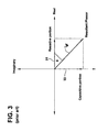
- FIG. 3 A conventional phasor diagram for the ground fault current Ig of FIG. 2 is shown in FIG. 3 .
- the reactive, imaginary current component 33 flowing through the capacitance is shown at a right angle to the resistive, real current component 31.
- the imaginary current component 33 is purely reactive so it does not cause heating and does not present a shock hazard.
- the reactive current component 33 of the ground fault current does not necessitate tripping of the GFCI device 22 ( FIG 2 ).
- the resistive component 31 does cause heating and does present a shock hazard.
- the real component 31 of the current I gf necessitates the GFCI device 22 ( FIG 2 ) to trip at predetermined current levels; the imaginary component 33 does not.
- a relatively high capacitance-to-ground is common on single and three-phase electrical distribution systems having voltages greater than 120 volts line-to-ground and results in a characteristic capacitive current.
- the relatively high capacitance-to-ground can be caused by various factors such as long conductors to a load, or by phase-to-ground capacitors connected in the circuit.
- the reactive portion 33 of the ground fault I gf is known to cause nuisance tripping of conventional ground fault devices 22 ( FIG 2 ).
- Such conventional devices have not been able to distinguish between the resistive (real) portion 31 of the ground fault and the reactive (imaginary) portion 33 of the ground fault current at the higher voltages.
- ground fault zero crossings may alter timing measurement of the conventional method, thus resulting in an incorrect zero crossing measurement.
- controller since the controller must generate a pulse and measure pulses in order to determine the zero crossings and measure the time between zero crossings, the prior art methods can be complicated and subject to signaling errors.
- one or more embodiments shown and/or described herein provide a device and method to determine the presence of a ground fault that distinguishes between the capacitive portion of the currents to ground, and the resistive portion of the currents to ground by ascertaining aspects of a waveform rather than a segment thereof.
- the real portion of a reference phasor is considered to be the resistive portion of a ground fault current and compared to a predetermined threshold, the reference phasor being determined based on the real and imaginary portions of an AC voltage and an AC ground fault current.
- An advantage over the conventional methods afforded by various embodiments of the present invention is that the detection of a ground fault current that requires interruption of current flow for personnel protection can, more simply and with less sensitivity to noise, be discerned from a ground fault current that does not require an interruption of current flow for personnel protection.
- the detailed description is divided into two sections.
- the first section describes method embodiments.
- the second section describes apparatus embodiments.
- the present invention provides an improved method and device to discern an AC ground fault current having a resistive portion at a magnitude that requires interruption of the current flow by distinguishing between the resistive portion and the capacitive portion of the current to ground and both the real (resistive) and imaginary (reactive) portions of the voltage supplying the ground fault current.
- Eq. 01 may alternatively be illustrated in a phasor diagram.
- a method to determine the presence in a circuit of a real portion of a ground fault current above a predetermined threshold, and interrupting current flow is implemented as a computer data signal embodied in a carrier wave, that represents a sequence of computer-executable instructions which, when executed by a processor cause the processor to perform the respective method, or any suitable combination of parts thereof.
- a method to determine the presence in a circuit of a real portion of a ground fault current above a predetermined threshold, and interrupting current flow is implemented as a computer-accessible medium having computer-executable instructions configured to direct a computer, a processor, or a microprocessor to perform the respective method, or any suitable combination of parts thereof.
- the computer- accessible medium is a magnetic medium, an electronic medium, or an optical medium.
- Embodiments are described in terms of a computer, processor, or microprocessor executing the sequence of computer-executable instructions. However, some embodiments can be implemented entirely in computer hardware in which the computer-executable instructions are implemented in read-only memory. Some embodiments can also be implemented in client/server computing environments where remote devices that perform tasks are linked through a communications network. Program nodules can be located in both local and remote memory storage devices in distributed computing environments.
- FIG. 4 is a flow chart illustrating exemplary steps in determining the presence in a circuit of a real portion of a ground fault current above a predetermined threshold, and providing a trip signal will be described herein with occasional reference to the phasor diagram of Figs 6a and 6b .
- the method 400 begins at step 410 by measuring a line voltage and a residual current in the circuit.
- a phasor representation 612 ( FIG.6a ) of the line voltage having a real and an imaginary portion is then produced by multiplying the value of the line voltage measured in step 410 by a first and a second predetermined sinusoidal waveform.
- the first predetermined sinusoidal waveform is used to generate the real portion of the line voltage
- the second predetermined sinusoidal waveform is used to generate the imaginary portion of the line voltage.
- the first and the second predetermined sinusoidal waveforms are preferably each 90 degrees out of phase from each other, and are preferably selected to match the frequency of the voltage in the circuit.
- the first and second predetermined sinusoidal waveforms may be stored, for example in a memory of a microcontroller.
- a phasor representation 617 ( FIG. 6a ) of the residual current, having a real and an imaginary portion, is produced by multiplying the value of the residual current determined in step 410 by a third and a fourth predetermined sinusoidal waveform.
- the third predetermined sinusoidal waveform is used to generate the real portion of the line current
- the fourth predetermined sinusoidal waveform is used to generate the imaginary portion of the line current.
- the third and the fourth predetermined sinusoidal waveforms are preferably each 90 degrees out of phase from each other, and are preferably selected to match the frequency of the current in the circuit.
- the third and the fourth predetermined sinusoidal waveforms may be stored, for example in a memory of a microcontroller.
- a magnitude of the line voltage phasor is calculated.
- a complex conjugate 620 ( FIG. 6a ) of the line voltage phasor 612 ( FIG. 6a ) is generated by determining a negative of the imaginary portion, or phase angle, of the line voltage phasor 612 ( FIG. 6a ).
- the residual current phasor 617( FIG. 6a ) is multiplied by the conjugated line voltage phasor 620 ( FIG. 6a ) generated at step 440 to generate a phasor representation of a ground fault current 640 ( FIG. 6b ).
- the ground fault current phasor 640 ( FIG.6b ) generated at step 450 is divided by the magnitude of the line voltage phasor determined at step 430 to determine a real portion 650 ( FIG. 6b ) of the ground fault current.
- the real portion 650 ( FIG. 6b ) of the ground fault current determined at step 460 is compared to a threshold or predetermined level of ground fault current. If the real portion 650 ( FIG. 6b ) of the ground fault current is above the predetermined level of ground fault current, then at step 480, a true ground fault condition is determined to exist.
- a trip signal is triggered.
- the trip signal initiates opening the circuit, for example by tripping a circuit breaker, to remove the ground fault condition.
- the trip signal may trigger a warning of the determined ground fault hazard, and may or may not additionally trigger tripping a circuit breaker, to remove the ground fault condition.
- FIG. 5 is a flow chart illustrating alternative exemplary steps involved in computing the real portion of a ground fault.
- the method 500 begins at step 510 by measuring a line voltage and a residual current in the circuit.
- a phasor representation 612 ( FIG.6a ) of the line voltage having a real and an imaginary portion is then produced by multiplying the value of the line voltage measured in step 510 by a first and a second predetermined sinusoidal waveform.
- the first predetermined sinusoidal waveform is used to generate the real portion of the line voltage
- the second predetermined sinusoidal waveform is used to generate the imaginary portion of the line voltage.
- the first and the second predetermined sinusoidal waveforms are preferably each 90 degrees out of phase from each other, and are preferably selected to match the frequency of the voltage in the circuit.
- the first and second predetermined sinusoidal waveforms may be stored, for example in a memory of a microcontroller.
- a phasor representation 617 ( FIG. 6a ) of the residual current, having a real and an imaginary portion, is produced by multiplying the value of the residual current determined in step 510 by a third and a fourth predetermined sinusoidal waveform.
- the third predetermined sinusoidal waveform is used to generate the real portion of the line current
- the fourth predetermined sinusoidal waveform is used to generate the imaginary portion of the line current.
- the third and the fourth predetermined sinusoidal waveforms are preferably each 90 degrees out of phase from each other, and are preferably selected to match the frequency of the current in the circuit.
- the third and the fourth predetermined sinusoidal waveforms may be stored, for example in a memory of a microcontroller.
- a magnitude of the line voltage phasor is calculated.
- a complex conjugate 620 ( FIG. 6a ) of the line voltage phasor 612 ( FIG. 6a ) is generated by determining a negative of the imaginary portion, or phase angle, of the line voltage phasor 612 ( FIG. 6a ).
- the residual current phasor 617( FIG. 6a ) is multiplied by the conjugated line voltage phasor 620 ( FIG. 6a ) generated at step 540 to generate a phasor representation of a ground fault current 640 ( FIG. 6b ).
- the ground fault current phasor 640 ( FIG.6b ) generated at step 550 is divided by the magnitude of the line voltage phasor determined at step 530 to determine a real portion 650 ( FIG. 6b ) of the ground fault current.
- the above steps 510 - 560 are repeatedly followed for a predetermined period, such as for example several electrical cycles, to generate corresponding resultant phasors.
- the determined real portion of the ground fault current 650 ( FIG. 6b ) for each resultant phasor is averaged to determine an average real portion of the ground fault current.
- the average real portion of the ground fault current determined at step 567 is then compared to a threshold or predetermined level of ground fault current. If the real portion of the ground fault current is above the predetermined level of ground fault current, a true ground fault condition is determined to exist.
- a trip signal is triggered.
- the trip signal initiates opening the circuit, for example by tripping a circuit breaker, to remove the ground fault condition.
- the trip signal may trigger a warning of the determined ground fault hazard, and may or may not additionally trigger tripping a circuit breaker, to remove the ground fault condition.
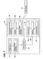
- a current sensor 44 provides an indication of residual current to an amplifier 44b and a first analog-to-digital (A-D) converter 44a.
- the current sensor 44 is a zero-sequence type current transformer (CT) having a primary and a secondary coil, configured to have a line conductor 15 ( FIG. 1 ) and a neutral conductor 16 ( FIG. 1 ) of a conventional circuit pass through the primary coil.
- CT zero-sequence type current transformer
- the amplifier 44b comprises two cascaded non-inverting amplifiers.
- the first A-D converter 44a provides a digital indication of the sensed residual current to a Microcontroller 46 for processing.
- Microcontroller 46 performs computational, timing, memory, and display functions.
- a voltage sensor 43 detects a voltage between line conductor 15 ( FIG. 1 ) and neutral conductor 16 ( FIG. 1 ) of the protected circuit and provides an indication of the detected voltage to a second analog-to-digital (A-D) converter 43a.
- the line voltage is detected across a burden resistor connected across the current transformer 44 secondary coil to ground.
- the second A-D converter 43a provides a digital indication of the sensed voltage to a microcontroller 46 for processing.
- interrupter 48 includes a solenoid driver circuit 48a in communication with a trip solenoid 48b for actuating the trip solenoid 48b.
- Trip solenoid 48b when energized, actuates a trip mechanism 48c to trip or open the GFCI 42.
- GFCI 42 may be self-powered, for example using power from the protected circuit (not shown), or may use a stand-alone power source 49, such as for example, a battery.
Landscapes
- Engineering & Computer Science (AREA)
- Power Engineering (AREA)
- Emergency Protection Circuit Devices (AREA)
- Testing Of Short-Circuits, Discontinuities, Leakage, Or Incorrect Line Connections (AREA)
- Locating Faults (AREA)
Abstract
Description
- The field of the invention relates to electrical ground fault protection generally, and more particularly to certain new and useful advances in devices and methods for ground fault detection and interruption of which the following is a specification, reference being had to the drawings accompanying and forming a part of the same.
- A ground fault is an undesirable condition in an electrical system, in which electrical current flows to the ground. A ground fault happens when the electrical current in a circuit leaks outside of its intended flow path. Ground fault circuit interrupters (GFCIs) or residual current devices (RCDs) are designed to protect such electrical hazards by interrupting a circuit when there is a ground fault, or residual current, such as a leakage of electrical current from an energized line conductor to ground. Conventional electric circuits normally carry balanced electrical currents, with the return current from an electrical load flowing through a neutral conductor. If no ground fault current is flowing, the phase and neutral currents of a branch circuit will sum to zero. In the event of a ground fault, the phase and neutral currents do not sum to zero and the difference between the phase and neutral currents is the ground fault current.
- In some instances, the ground fault may result in lethal shocks or electrocution, such as in the case of a person who makes inadvertent contact with the phase conductor. The U.S. National Electrical Code (NEC) requires ground fault protection for both electric shock and equipment protection. A conventional GFCI is designed to detect predetermined levels (typically in the range of 4 to 6 milliamperes) of differential currents and to open the circuit, for example by tripping a circuit breaker, to remove the indicated shock hazard. If a differential current below the predetermined level is detected, current is normally allowed to flow uninterrupted. In some instances, ground fault protection devices alternatively provide a warning of a ground fault hazard but do not interrupt current flowing in the affected circuit, for example in fire protection applications where the ground current hazard is considered less dangerous than interrupting the current to fire prevention equipment.
-
Fig. 1 shows a conventionalelectrical circuit 10 such as a branch circuit having anAC power source 11 providing electrical power to aload 17. Theload 17 is housed in anenclosure 18 which is connected to ground via aconductor 19. Aconventional GFCI device 12 havingswitching contacts phase conductor 15, connected between thesource 11 andload 17, and aneutral return conductor 16, connected between theload 17 andsource 11, using a differentialcurrent transformer 14. A current Ip flowing inphase conductor 15 and a return current Ir flowing inneutral conductor 16 are equal in magnitude (that is, the vector sum of Ip and Ir is zero) and no ground fault or residual current is flowing. TheGFCI device 12 is configured to opencontacts source 11 to load 17 when it detects a difference in current between the phase andneutral conductors -
FIG. 2 shows the circuitFIG. 1 but with a ground fault current Igf flowing in the groundedconductor 19 caused by a high impedance short-circuit 20 between thephase conductor 15 and the groundedenclosure 18. The value of the ground fault current Igf is a vector sum of the currents Ip, and Ir flowing in thecircuit 10 and can be expressed as a phasor, having both magnitude and phase. - It is well known that for conventional electrical systems, analysis of sinusoidal AC current and voltage performance is simplified by using a phasor characterization of the sinusoids. Such phasor characterization uses complex numbers, having "real"components associated with resistive elements, and "imaginary" components associated with reactive elements. Phasors are represented alternatively in polar or rectangular form on the complex plane. The rectangular representation of a phasor for an AC signal comprises both a real component and an imaginary component. The polar representation of a phasor for an AC signal comprises both a magnitude and an angle.
- A conventional phasor diagram for the ground fault current Ig of
FIG. 2 is shown inFIG. 3 . InFIG. 3 , the reactive, imaginarycurrent component 33 flowing through the capacitance is shown at a right angle to the resistive, realcurrent component 31. The imaginarycurrent component 33 is purely reactive so it does not cause heating and does not present a shock hazard. Thus, the reactivecurrent component 33 of the ground fault current does not necessitate tripping of the GFCI device 22 (FIG 2 ). In contrast, theresistive component 31 does cause heating and does present a shock hazard. Thus, only thereal component 31 of the current Igf necessitates the GFCI device 22 (FIG 2 ) to trip at predetermined current levels; theimaginary component 33 does not. - It will be understood that in conventional electrical systems there is generally a capacitance between the circuit conductors and ground. A relatively high capacitance-to-ground is common on single and three-phase electrical distribution systems having voltages greater than 120 volts line-to-ground and results in a characteristic capacitive current. The relatively high capacitance-to-ground can be caused by various factors such as long conductors to a load, or by phase-to-ground capacitors connected in the circuit.
- One problem that occurs with conventional GFCI devices in circuits with a high capacitance-to-ground is unnecessary or nuisance tripping caused by the capacitive current to ground in the absence of a real, or resistive, ground fault condition. That is, the capacitive, or reactive, currents can exceed the predetermined ground fault current threshold of conventional GFCI devices and result in a nuisance tripping of the GFCI in the protected circuits.
- At voltages above 120VAC, and at relatively low ground fault current trip settings in the milliamp range, the
reactive portion 33 of the ground fault Igf, is known to cause nuisance tripping of conventional ground fault devices 22 (FIG 2 ). Such conventional devices have not been able to distinguish between the resistive (real)portion 31 of the ground fault and the reactive (imaginary)portion 33 of the ground fault current at the higher voltages. - Conventional methods of detect hazardous ground faults and distinguishing between real and imaginary parts of the ground fault current have determined a phase angle between the ground fault and phase currents, and measured a period of the ground fault alternating current and phase currents between respective zero crossings, and divided the respective time periods of the ground fault and phase currents. Additionally, the ground fault signal, and the measured period between respective zero crossings signal have been provided as one or more pulse signals to a controller.
- One known shortcoming of such a conventional method, in the instance that the ground current is noisy or non-sinusoidal, the ground fault zero crossings may alter timing measurement of the conventional method, thus resulting in an incorrect zero crossing measurement. Moreover, since the controller must generate a pulse and measure pulses in order to determine the zero crossings and measure the time between zero crossings, the prior art methods can be complicated and subject to signaling errors.
- For at least the reasons stated above, a need exists for an improved device and method to detect hazardous ground faults on single phase and multi-phase circuits at voltages over 120VAC.
- One or more specific embodiments shown and/or described herein address at least the above-mentioned need.
- Additionally, one or more embodiments shown and/or described herein provide a device and method to determine the presence of a ground fault that distinguishes between the capacitive portion of the currents to ground, and the resistive portion of the currents to ground by ascertaining aspects of a waveform rather than a segment thereof.
- In one embodiment, the real portion of a reference phasor is considered to be the resistive portion of a ground fault current and compared to a predetermined threshold, the reference phasor being determined based on the real and imaginary portions of an AC voltage and an AC ground fault current.
- An advantage over the conventional methods afforded by various embodiments of the present invention is that the detection of a ground fault current that requires interruption of current flow for personnel protection can, more simply and with less sensitivity to noise, be discerned from a ground fault current that does not require an interruption of current flow for personnel protection.
- Apparatus and methods of varying scope are shown and described herein. In addition to the advantages described above, further advantages and/or adaptations or variations will become apparent by reference to the drawings and by reading the remaining portions of the specification.
- A more complete appreciation of the invention and many of the attendant advantages thereof will be readily obtained as the same becomes better understood by reference to the following detailed description when considered in connection with the accompanying drawings. The accompanying drawings, which are incorporated in and constitute a part of the specification, illustrate a presently preferred embodiment of the invention, in which:
-
FIG. 1 is a schematic diagram of a conventional electric circuit having a conventional GFCI; -
FIG. 2 is a schematic diagram of the conventional circuit ofFIG. 1 wherein a ground fault condition exists; -
FIG. 3 is a conventional phasor diagram of a typical sinusoidal electrical waveform; -
FIG. 4 is a process flow of an embodiment of a method of the present invention; -
FIG. 5 is a process flow of an alternative embodiment of a method of the present invention; -
FIGS. 6a, and 6b are phasor diagrams illustrating elements of the embodiments ofFIG. 4 andFIG. 5 ; and -
FIG. 7 is a functional diagram of an embodiment a device of the present invention. - Like reference characters designate identical or corresponding components and units throughout the several views, which are not to scale unless otherwise indicated.
- The following description makes reference to the accompanying drawings that form a part hereof, and in which is shown by way of illustration specific embodiments that may be practiced. It is understood that other embodiments may be utilized and that various changes can be made to the embodiments shown and described herein without departing from the patentable scope of the claims appended hereto. The following description is, therefore, not to be taken in a limiting sense.
- As used herein, an element or function recited in the singular and proceeded with the word "a" or "an" should be understood as not excluding plural said elements or functions, unless such exclusion is explicitly recited. Furthermore, references to "one embodiment" of the claimed invention should not be interpreted as excluding the existence of additional embodiments that also incorporate the recited features.
- The detailed description is divided into two sections. The first section describes method embodiments. The second section describes apparatus embodiments.
- The present invention provides an improved method and device to discern an AC ground fault current having a resistive portion at a magnitude that requires interruption of the current flow by distinguishing between the resistive portion and the capacitive portion of the current to ground and both the real (resistive) and imaginary (reactive) portions of the voltage supplying the ground fault current.
- For a given circuit having a ground fault current Igf , the current Igf can be determined by the ratio of the real portion of the product of the residual current Ir (i.e., the sum of the phase and neutral currents) and the complex conjugate of line or phase to neutral Voltage, V, to the Absolute value of phase to neutral Voltage, V, and may be represented in phasor format as:

- Additionally, graphical representations of Eq. 01 may alternatively be illustrated in a phasor diagram.
- This section describes particular methods that can be performed by a computer, a processor, or a microprocessor. The methods are described by reference to a flowchart or a series of flowcharts.
- In some embodiments, a method to determine the presence in a circuit of a real portion of a ground fault current above a predetermined threshold, and interrupting current flow, is implemented as a computer data signal embodied in a carrier wave, that represents a sequence of computer-executable instructions which, when executed by a processor cause the processor to perform the respective method, or any suitable combination of parts thereof. In other embodiments, a method to determine the presence in a circuit of a real portion of a ground fault current above a predetermined threshold, and interrupting current flow is implemented as a computer-accessible medium having computer-executable instructions configured to direct a computer, a processor, or a microprocessor to perform the respective method, or any suitable combination of parts thereof. In various embodiments, the computer- accessible medium is a magnetic medium, an electronic medium, or an optical medium. Embodiments are described in terms of a computer, processor, or microprocessor executing the sequence of computer-executable instructions. However, some embodiments can be implemented entirely in computer hardware in which the computer-executable instructions are implemented in read-only memory. Some embodiments can also be implemented in client/server computing environments where remote devices that perform tasks are linked through a communications network. Program nodules can be located in both local and remote memory storage devices in distributed computing environments.
-
FIG. 4 is a flow chart illustrating exemplary steps in determining the presence in a circuit of a real portion of a ground fault current above a predetermined threshold, and providing a trip signal will be described herein with occasional reference to the phasor diagram ofFigs 6a and 6b . In the illustrated embodiment, themethod 400 begins atstep 410 by measuring a line voltage and a residual current in the circuit. - At
step 415a, a phasor representation 612 (FIG.6a ) of the line voltage having a real and an imaginary portion is then produced by multiplying the value of the line voltage measured instep 410 by a first and a second predetermined sinusoidal waveform. The first predetermined sinusoidal waveform is used to generate the real portion of the line voltage, and the second predetermined sinusoidal waveform is used to generate the imaginary portion of the line voltage. The first and the second predetermined sinusoidal waveforms are preferably each 90 degrees out of phase from each other, and are preferably selected to match the frequency of the voltage in the circuit. The first and second predetermined sinusoidal waveforms may be stored, for example in a memory of a microcontroller. - At
step 415b, a phasor representation 617 (FIG. 6a ) of the residual current, having a real and an imaginary portion, is produced by multiplying the value of the residual current determined instep 410 by a third and a fourth predetermined sinusoidal waveform. The third predetermined sinusoidal waveform is used to generate the real portion of the line current, and the fourth predetermined sinusoidal waveform is used to generate the imaginary portion of the line current. The third and the fourth predetermined sinusoidal waveforms are preferably each 90 degrees out of phase from each other, and are preferably selected to match the frequency of the current in the circuit. The third and the fourth predetermined sinusoidal waveforms may be stored, for example in a memory of a microcontroller. - At
step 430, a magnitude of the line voltage phasor, is calculated. - At
step 440, a complex conjugate 620 (FIG. 6a ) of the line voltage phasor 612 (FIG. 6a ) is generated by determining a negative of the imaginary portion, or phase angle, of the line voltage phasor 612 (FIG. 6a ). - At
step 450, the residual current phasor 617(FIG. 6a ) is multiplied by the conjugated line voltage phasor 620 (FIG. 6a ) generated atstep 440 to generate a phasor representation of a ground fault current 640 (FIG. 6b ). - At
step 460, the ground fault current phasor 640 (FIG.6b ) generated atstep 450 is divided by the magnitude of the line voltage phasor determined atstep 430 to determine a real portion 650 (FIG. 6b ) of the ground fault current. - At
step 470, the real portion 650 (FIG. 6b ) of the ground fault current determined atstep 460 is compared to a threshold or predetermined level of ground fault current. If the real portion 650 (FIG. 6b ) of the ground fault current is above the predetermined level of ground fault current, then atstep 480, a true ground fault condition is determined to exist. - If a true ground fault condition is determined to exist, then at
step 490, a trip signal is triggered. The trip signal initiates opening the circuit, for example by tripping a circuit breaker, to remove the ground fault condition. Alternatively, the trip signal may trigger a warning of the determined ground fault hazard, and may or may not additionally trigger tripping a circuit breaker, to remove the ground fault condition. -
FIG. 5 is a flow chart illustrating alternative exemplary steps involved in computing the real portion of a ground fault. In the illustrated embodiment, themethod 500 begins atstep 510 by measuring a line voltage and a residual current in the circuit. - At
step 515a, a phasor representation 612 (FIG.6a ) of the line voltage having a real and an imaginary portion is then produced by multiplying the value of the line voltage measured instep 510 by a first and a second predetermined sinusoidal waveform. The first predetermined sinusoidal waveform is used to generate the real portion of the line voltage, and the second predetermined sinusoidal waveform is used to generate the imaginary portion of the line voltage. The first and the second predetermined sinusoidal waveforms are preferably each 90 degrees out of phase from each other, and are preferably selected to match the frequency of the voltage in the circuit. The first and second predetermined sinusoidal waveforms may be stored, for example in a memory of a microcontroller. - At
step 515b, a phasor representation 617 (FIG. 6a ) of the residual current, having a real and an imaginary portion, is produced by multiplying the value of the residual current determined instep 510 by a third and a fourth predetermined sinusoidal waveform. The third predetermined sinusoidal waveform is used to generate the real portion of the line current, and the fourth predetermined sinusoidal waveform is used to generate the imaginary portion of the line current. The third and the fourth predetermined sinusoidal waveforms are preferably each 90 degrees out of phase from each other, and are preferably selected to match the frequency of the current in the circuit. The third and the fourth predetermined sinusoidal waveforms may be stored, for example in a memory of a microcontroller. - At
step 530, a magnitude of the line voltage phasor, is calculated. - At
step 540, a complex conjugate 620 (FIG. 6a ) of the line voltage phasor 612 (FIG. 6a ) is generated by determining a negative of the imaginary portion, or phase angle, of the line voltage phasor 612 (FIG. 6a ). - At
step 550, the residual current phasor 617(FIG. 6a ) is multiplied by the conjugated line voltage phasor 620 (FIG. 6a ) generated atstep 540 to generate a phasor representation of a ground fault current 640 (FIG. 6b ). - At
step 560, the ground fault current phasor 640 (FIG.6b ) generated atstep 550 is divided by the magnitude of the line voltage phasor determined atstep 530 to determine a real portion 650 (FIG. 6b ) of the ground fault current. - At
step 565, the above steps 510 - 560 are repeatedly followed for a predetermined period, such as for example several electrical cycles, to generate corresponding resultant phasors. Atstep 567, the determined real portion of the ground fault current 650 (FIG. 6b ) for each resultant phasor is averaged to determine an average real portion of the ground fault current. The average real portion of the ground fault current determined atstep 567 is then compared to a threshold or predetermined level of ground fault current. If the real portion of the ground fault current is above the predetermined level of ground fault current, a true ground fault condition is determined to exist. - If a true ground fault condition is determined to exist, then at step 570, a trip signal is triggered. The trip signal initiates opening the circuit, for example by tripping a circuit breaker, to remove the ground fault condition. Alternatively, the trip signal may trigger a warning of the determined ground fault hazard, and may or may not additionally trigger tripping a circuit breaker, to remove the ground fault condition.
- The previous section described a method of how an embodiment of the invention operates. This section describes a particular apparatus of such an embodiment with reference to
FIG. 7 . - One embodiment of a
GFCI device 42 of the present invention for ground fault detection in a circuit is shown in functional block diagram representation inFIG. 7 . Acurrent sensor 44 provides an indication of residual current to anamplifier 44b and a first analog-to-digital (A-D)converter 44a. In one exemplary embodiment, thecurrent sensor 44 is a zero-sequence type current transformer (CT) having a primary and a secondary coil, configured to have a line conductor 15 (FIG. 1 ) and a neutral conductor 16 (FIG. 1 ) of a conventional circuit pass through the primary coil. In one embodiment, theamplifier 44b comprises two cascaded non-inverting amplifiers. - The first
A-D converter 44a provides a digital indication of the sensed residual current to aMicrocontroller 46 for processing.Microcontroller 46 performs computational, timing, memory, and display functions. Avoltage sensor 43 detects a voltage between line conductor 15 (FIG. 1 ) and neutral conductor 16 (FIG. 1 ) of the protected circuit and provides an indication of the detected voltage to a second analog-to-digital (A-D)converter 43a. In one exemplary embodiment, the line voltage is detected across a burden resistor connected across thecurrent transformer 44 secondary coil to ground. The secondA-D converter 43a provides a digital indication of the sensed voltage to amicrocontroller 46 for processing. In an alternative embodiment, the analog-to-digital conversion of the detected line voltage signal and residual current may alternatively be made by themicrocontroller 46 instead of theA-D converters microcontroller 46 and a trip signal is provided bymicrocontroller 46 to aninterrupter 48 portion ofGFCI 42. In one embodiment,interrupter 48 includes asolenoid driver circuit 48a in communication with atrip solenoid 48b for actuating thetrip solenoid 48b.Trip solenoid 48b, when energized, actuates atrip mechanism 48c to trip or open theGFCI 42.GFCI 42 may be self-powered, for example using power from the protected circuit (not shown), or may use a stand-alone power source 49, such as for example, a battery. - This specification, including the claims, abstract and drawings, is intended to cover any adaptations or variations of the specific embodiments illustrated and described herein. Accordingly, the names of elements, components or features, of the above-described system, methods, and apparatus are not intended to be limiting. It is contemplated that the above-described embodiments, whether adapted or varied or not, are applicable to future GFCI apparatus and methods. Moreover, the terminology used herein is intended to encompass all GFCI apparatus and methods that provide the same or equivalent functionality described herein.
- Although effort was made to show all of the particular elements, components or features of each of the above-described specific embodiments in separate figures, this may not have been possible. In the event that one or more elements, components or features of one or more of the above-described specific embodiments are shown in some drawings and not in others, it is contemplated that each element, component or feature of one drawing may be combined with any or all of the other elements, components or features shown in any or all of the remainder of the drawings, as described herein, as claimed herein or in any other suitable fashion.
- The words "including", "comprising", "having", and "with" as used herein are to be interpreted broadly and comprehensively and are not limited to any physical interconnection. Additionally, patentable scope is defined by the following claims, which are intended to encompass not only the specific embodiments described above, but also adaptations or variations thereof (i) that have structural elements that do not differ from the literal language of the claims, or (ii) that have equivalent structural elements with insubstantial differences from the literal language of the claims.
Claims (8)
- A method to detect ground fault in an electrical circuit (10) having a current flow at an AC voltage, comprising:a) determining a first phasor (617) associated with said current flow;b) determining a second phasor (612) associated with said voltage;c) calculating a complex conjugate (620) of said second phasor (612)d) calculating a third reference phasor (640) as a product of said first phasor (617) and said complex conjugate (620) of said second phasor (612);e) normalizing the real portion (650) of said third phasor (640) with respect to a magnitude of said second phasor (612);f) determining if said normalized real portion (650) of said third phasor (640) is above a predetermined threshold; and if so,g) producing a trip signal.
- The method of claim 1 further comprising transforming said first phasor (617) associated with said current flow and said second phasor (612) associated with said voltage via a Discrete Fourier Transformation at the fundamental frequency of the voltage.
- A method to detect ground fault in an electrical circuit (10) having a current flow at an AC voltage, comprising:a) determining a first phasor (617) associated with said current flow;b) determining a second phasor (612) associated with said line voltage;c) calculating a complex conjugate (620) of said second phasor (612)d) calculating a third phasor (640) as a product of said first phasor (617) and said complex conjugate (620) of said second phasor (612);e) normalizing the real portion (650) of said third phasor (640) with respect to a magnitude of said second phasor (612);f) determining an average value of said normalized real portion (650) of said third phasor (640) over a predetermined period;g) comparing said average value of said normalized real portion (650) of said third phasor (640) to a predetermined threshold;h) determining if said average value of said normalized real portion (650) of said third phasor (640) is above said predetermined threshold; and if so,i) producing a trip signal.
- The method of claim 3 further comprising transforming said first phasor (617) associated with said current flow and said second phasor (612) associated with said voltage via a Discrete Fourier Transformation at the fundamental frequency of the voltage.
- A device configured to detect a ground fault in an electrical circuit (10) having an AC voltage and a current, comprising:a ground fault current interrupter (48) configured to trip in response to the ground fault;a control circuit in signal communication with said ground fault detector;said control circuit being configured to:a) determine a first phasor (617) associated with said current flow;b) determine a second phasor (612) associated with said line voltage;c) calculate a complex conjugate (620) of said second phasor (612)d) calculate a third reference phasor as a product of said first phasor (617) and said complex conjugate (620) of said second phasor (612);e) normalize the real portion (650) of said third phasor (640) with respect to a magnitude of said second phasor (612);f) determine if said normalized real portion (650) of said third phasor (640) is above a predetermined threshold; and if so,g) provide a trip signal to said ground fault current interrupter.
- The device of claim 5 wherein said control circuit is further configured to transform said first phasor (617) associated with said current flow and said second phasor (612) associated with said line voltage via a Discrete Fourier Transformation at the fundamental frequency of the voltage signal.
- A device for detecting a ground fault in an electrical circuit (10) having an AC voltage and a current, comprising:a ground fault current interrupter (48) configured to trip in response to the ground fault;a control circuit in signal communication with said ground fault detector;said control circuit being configured to:a) determine a first phasor (617) associated with said current flow;b) determine a second phasor (612) associated with said line voltage;c) calculate a complex conjugate (620) of said second phasor (612)d) calculate a third phasor (640) as a product of said first phasor (617) and said complex conjugate (620) of said second phasor (612);e) normalize the real portion (650) of said third phasor (640) with respect to a magnitude of said second phasor (612);f) determine an average value of said normalized real portion (650) of said third phasor (640) over a predetermined period;g) compare said average value of said normalized real portion (650) of said third phasor (640) to a predetermined threshold;h) determine if said average value of said normalized real portion (650) of said third phasor (640) is above said predetermined threshold; and if so,i) provide a trip signal to said ground fault current interrupter.
- The device of claim 7 wherein said control circuit is further configured to transform said first phasor (617) associated with said current flow and said second phasor (612) associated with said line voltage via a Discrete Fourier Transformation at the fundamental frequency of the voltage signal.
Applications Claiming Priority (1)
| Application Number | Priority Date | Filing Date | Title |
|---|---|---|---|
| US12/565,862 US7944213B2 (en) | 2009-09-24 | 2009-09-24 | Ground fault detection device |
Publications (2)
| Publication Number | Publication Date |
|---|---|
| EP2306609A2 true EP2306609A2 (en) | 2011-04-06 |
| EP2306609A3 EP2306609A3 (en) | 2017-04-19 |
Family
ID=43033171
Family Applications (1)
| Application Number | Title | Priority Date | Filing Date |
|---|---|---|---|
| EP10178720.8A Pending EP2306609A3 (en) | 2009-09-24 | 2010-09-23 | Ground fault detection device |
Country Status (2)
| Country | Link |
|---|---|
| US (1) | US7944213B2 (en) |
| EP (1) | EP2306609A3 (en) |
Cited By (4)
| Publication number | Priority date | Publication date | Assignee | Title |
|---|---|---|---|---|
| FR2976414A1 (en) * | 2011-06-09 | 2012-12-14 | Alstom Grid Sas | METHOD FOR DIFFERENTIALLY PROTECTING A HIGH LENGTH ELECTRICAL CONNECTION WITH HIGH CAPACITIVE CURRENT IN A MEDIUM, HIGH OR VERY HIGH VOLTAGE NETWORK |
| EP3001524A1 (en) * | 2014-09-29 | 2016-03-30 | Schneider Electric Industries SAS | Directional detection of a ground fault in an electrical distribution network |
| EP3509177A1 (en) * | 2018-01-09 | 2019-07-10 | ABB Schweiz AG | Method for detecting earth-fault conditions in a power conversion apparatus |
| WO2020140583A1 (en) * | 2019-01-04 | 2020-07-09 | 中国南方电网有限责任公司超高压输电公司梧州局 | Detection device and method for distinguishing branches having capacitive or resistive instantaneous ground faults |
Families Citing this family (13)
| Publication number | Priority date | Publication date | Assignee | Title |
|---|---|---|---|---|
| US8618809B2 (en) * | 2010-06-15 | 2013-12-31 | Deere & Company | Electrical isolation detection with enhanced dynamic range |
| US9413178B2 (en) | 2011-11-11 | 2016-08-09 | General Electric Company | Charging device and method of detecting a connection to ground |
| US9046555B2 (en) * | 2011-12-19 | 2015-06-02 | Tyco Safety Products Canada Ltd. | Latching over-current protection circuit and method |
| EP2639914B1 (en) * | 2012-03-16 | 2015-07-22 | ABB Technology AG | Method and apparatus for adapting earth-fault protection settings in a three-phase electric network |
| CN104577944B (en) * | 2013-10-15 | 2017-12-15 | 西门子公司 | residual current device |
| US9915687B2 (en) * | 2015-03-27 | 2018-03-13 | Liebert Corporation | Real current meter |
| JP6517667B2 (en) * | 2015-11-05 | 2019-05-22 | 関西電力株式会社 | Ground fault detection device |
| JP6240918B1 (en) * | 2016-06-30 | 2017-12-06 | 共立電気計器株式會社 | Leakage current measuring method and leakage current measuring device |
| JP2018021812A (en) * | 2016-08-03 | 2018-02-08 | 共立電気計器株式會社 | Device and method for measuring leakage current |
| CN111610358B (en) * | 2020-05-27 | 2022-09-27 | 许昌中科森尼瑞技术有限公司 | Method for calculating residual current by collecting three-phase and zero-sequence currents under three-phase four-wire system |
| CN112881945B (en) * | 2021-04-21 | 2022-10-14 | 深圳市市政设计研究院有限公司 | Method and device for judging ground fault |
| DE102023207055A1 (en) * | 2023-07-25 | 2025-01-30 | Siemens Aktiengesellschaft | protective switching device and method |
| DE102023207056A1 (en) * | 2023-07-25 | 2025-01-30 | Siemens Aktiengesellschaft | protective switching device and method |
Family Cites Families (16)
| Publication number | Priority date | Publication date | Assignee | Title |
|---|---|---|---|---|
| GB679789A (en) | 1950-09-30 | 1952-09-24 | Wilfrid Brooke | Improvements in and relating to earth leakage protection for single phase a.c. circuits |
| US3611036A (en) * | 1970-01-21 | 1971-10-05 | Occidental Petroleum Corp | Ground fault detector for electric motors |
| US4216515A (en) * | 1973-03-28 | 1980-08-05 | Eaton Corporation | Ground fault interrupter |
| DE3626400A1 (en) * | 1986-08-04 | 1988-02-11 | Siemens Ag | ARRANGEMENT FOR THE FAST DETECTION OF SHORT-CIRCUITS |
| US4851782A (en) * | 1987-01-15 | 1989-07-25 | Jeerings Donald I | High impedance fault analyzer in electric power distribution |
| US5349490A (en) * | 1992-10-15 | 1994-09-20 | Schweitzer Engineering Laboratories, Inc. | Negative sequence directional element for a relay useful in protecting power transmission lines |
| JP3763852B2 (en) * | 1997-06-17 | 2006-04-05 | ディプロム−インジェニエール ヴァルター ベンダー ゲゼルシャフト ミット ベシュレンクテル ハフツング ウント コンパニー コマンディートゲゼルシャフト | Method and circuit for monitoring insulation and fault current in AC power supply |
| IES80796B2 (en) * | 1997-08-28 | 1999-02-24 | Electricity Supply Board | Fault detection apparatus and method of detecting faults in an electrical distribution network |
| US6141196A (en) * | 1998-03-02 | 2000-10-31 | General Electric Company | Method and apparatus for compensation of phasor estimations |
| JP3456952B2 (en) * | 2000-06-28 | 2003-10-14 | 株式会社東芝 | Digital type distance relay |
| US6459269B1 (en) * | 2001-04-02 | 2002-10-01 | Msx, Inc. | Capacitance rejecting ground fault protecting apparatus and method |
| US20050218906A1 (en) * | 2004-03-31 | 2005-10-06 | Younsi Abdelkrim K | System and method for monitoring of insulation condition |
| US7292420B2 (en) * | 2004-11-09 | 2007-11-06 | Msx, Incorporated | Apparatus for improved ground fault equipment protection |
| US7180300B2 (en) * | 2004-12-10 | 2007-02-20 | General Electric Company | System and method of locating ground fault in electrical power distribution system |
| US7301739B2 (en) * | 2005-10-12 | 2007-11-27 | Chevron U.S.A. Inc. | Ground-fault circuit-interrupter system for three-phase electrical power systems |
| WO2008072287A1 (en) * | 2006-12-08 | 2008-06-19 | Ohno, Takemi | Leakage current determining apparatus and leakage current determining method |
-
2009
- 2009-09-24 US US12/565,862 patent/US7944213B2/en active Active
-
2010
- 2010-09-23 EP EP10178720.8A patent/EP2306609A3/en active Pending
Non-Patent Citations (1)
| Title |
|---|
| None |
Cited By (8)
| Publication number | Priority date | Publication date | Assignee | Title |
|---|---|---|---|---|
| FR2976414A1 (en) * | 2011-06-09 | 2012-12-14 | Alstom Grid Sas | METHOD FOR DIFFERENTIALLY PROTECTING A HIGH LENGTH ELECTRICAL CONNECTION WITH HIGH CAPACITIVE CURRENT IN A MEDIUM, HIGH OR VERY HIGH VOLTAGE NETWORK |
| EP3001524A1 (en) * | 2014-09-29 | 2016-03-30 | Schneider Electric Industries SAS | Directional detection of a ground fault in an electrical distribution network |
| FR3026492A1 (en) * | 2014-09-29 | 2016-04-01 | Schneider Electric Ind Sas | DIRECTIONAL DETECTION OF EARTH FAULT IN AN ELECTRICAL DISTRIBUTION NETWORK |
| US10545184B2 (en) | 2014-09-29 | 2020-01-28 | Schneider Electric Industries Sas | Directional detection of earth faults in an electrical distribution network |
| EP3509177A1 (en) * | 2018-01-09 | 2019-07-10 | ABB Schweiz AG | Method for detecting earth-fault conditions in a power conversion apparatus |
| US10845427B2 (en) | 2018-01-09 | 2020-11-24 | Abb Schweiz Ag | Method for detecting earth-fault conditions in a power conversion apparatus |
| AU2018286627B2 (en) * | 2018-01-09 | 2024-04-04 | Abb Schweiz Ag | Method for detecting earth-fault conditions in a power conversion apparatus |
| WO2020140583A1 (en) * | 2019-01-04 | 2020-07-09 | 中国南方电网有限责任公司超高压输电公司梧州局 | Detection device and method for distinguishing branches having capacitive or resistive instantaneous ground faults |
Also Published As
| Publication number | Publication date |
|---|---|
| EP2306609A3 (en) | 2017-04-19 |
| US7944213B2 (en) | 2011-05-17 |
| US20110068802A1 (en) | 2011-03-24 |
Similar Documents
| Publication | Publication Date | Title |
|---|---|---|
| US7944213B2 (en) | Ground fault detection device | |
| RU2631025C2 (en) | Detection of direction of weakly resistant short circuit to earth of average voltage with help of linear correlation | |
| CN101685130B (en) | Directional detection of a ground fault | |
| CN106415286B (en) | System and method for impulse ground fault detection and localization | |
| CN103852691B (en) | The oriented detection of failure in the network of compensation or the earthed system for the neutral point that insulate | |
| US8300369B2 (en) | System and method for polyphase ground-fault circuit-interrupters | |
| Pope | A comparison of 100% stator ground fault protection schemes for generator stator windings | |
| US7196884B2 (en) | Apparatus and method for detecting the loss of a current transformer connection coupling a current differential relay to an element of a power system | |
| US8654487B2 (en) | Methods, systems, and apparatus and for detecting parallel electrical arc faults | |
| CN102262199B (en) | Fault Identification in three-phase electrical power system and oriented detection | |
| US20100020457A1 (en) | Protective Digital Relay Device | |
| CN111796202B (en) | Method and device for fault detection of transmission lines of power transmission system | |
| EP3560054B1 (en) | A method for detecting inrush and ct saturation and an intelligent electronic device therefor | |
| US20180159310A1 (en) | Arc fault circuit interrupter apparatus and methods using symmetrical component harmonic detection | |
| US10338122B2 (en) | Method and device for detecting a fault in an electrical network | |
| US20040264094A1 (en) | Protective control method and apparatus for power devices | |
| CN100405685C (en) | Ground fault detection device and method and relay including such device | |
| EP3312621B1 (en) | Leak current detecting device | |
| US5627712A (en) | Transformer differential relay | |
| US10871513B2 (en) | Differential protection method in an electrical power supply system and protective apparatus for carrying out a differential protection method | |
| US6173216B1 (en) | Protective relay with improved, sub-window cosine filter | |
| US20250321292A1 (en) | Method to detect single-phase-to-ground faults in electric power systems | |
| Krstivojevic et al. | A new algorithm for transformer ground fault protection | |
| US6154687A (en) | Modified cosine filters | |
| JP5190635B2 (en) | Device for detecting resistance ground fault current |
Legal Events
| Date | Code | Title | Description |
|---|---|---|---|
| PUAI | Public reference made under article 153(3) epc to a published international application that has entered the european phase |
Free format text: ORIGINAL CODE: 0009012 |
|
| AK | Designated contracting states |
Kind code of ref document: A2 Designated state(s): AL AT BE BG CH CY CZ DE DK EE ES FI FR GB GR HR HU IE IS IT LI LT LU LV MC MK MT NL NO PL PT RO SE SI SK SM TR |
|
| AX | Request for extension of the european patent |
Extension state: BA ME RS |
|
| PUAL | Search report despatched |
Free format text: ORIGINAL CODE: 0009013 |
|
| AK | Designated contracting states |
Kind code of ref document: A3 Designated state(s): AL AT BE BG CH CY CZ DE DK EE ES FI FR GB GR HR HU IE IS IT LI LT LU LV MC MK MT NL NO PL PT RO SE SI SK SM TR |
|
| AX | Request for extension of the european patent |
Extension state: BA ME RS |
|
| RIC1 | Information provided on ipc code assigned before grant |
Ipc: H02H 3/16 20060101ALI20170313BHEP Ipc: H02H 3/33 20060101AFI20170313BHEP |
|
| STAA | Information on the status of an ep patent application or granted ep patent |
Free format text: STATUS: REQUEST FOR EXAMINATION WAS MADE |
|
| 17P | Request for examination filed |
Effective date: 20171019 |
|
| RBV | Designated contracting states (corrected) |
Designated state(s): AL AT BE BG CH CY CZ DE DK EE ES FI FR GB GR HR HU IE IS IT LI LT LU LV MC MK MT NL NO PL PT RO SE SI SK SM TR |
|
| RAP1 | Party data changed (applicant data changed or rights of an application transferred) |
Owner name: ABB SCHWEIZ AG |
|
| STAA | Information on the status of an ep patent application or granted ep patent |
Free format text: STATUS: EXAMINATION IS IN PROGRESS |
|
| 17Q | First examination report despatched |
Effective date: 20191115 |
|
| RAP3 | Party data changed (applicant data changed or rights of an application transferred) |
Owner name: ABB SCHWEIZ AG |