EP2306591A1 - Connector module and plug-in module system - Google Patents
Connector module and plug-in module system Download PDFInfo
- Publication number
- EP2306591A1 EP2306591A1 EP10176839A EP10176839A EP2306591A1 EP 2306591 A1 EP2306591 A1 EP 2306591A1 EP 10176839 A EP10176839 A EP 10176839A EP 10176839 A EP10176839 A EP 10176839A EP 2306591 A1 EP2306591 A1 EP 2306591A1
- Authority
- EP
- European Patent Office
- Prior art keywords
- connector module
- rotary knob
- electrical component
- bus bar
- face
- Prior art date
- Legal status (The legal status is an assumption and is not a legal conclusion. Google has not performed a legal analysis and makes no representation as to the accuracy of the status listed.)
- Withdrawn
Links
- 238000006073 displacement reaction Methods 0.000 description 6
- 238000009434 installation Methods 0.000 description 3
- 238000005516 engineering process Methods 0.000 description 2
- 230000015572 biosynthetic process Effects 0.000 description 1
- 230000000903 blocking effect Effects 0.000 description 1
- 238000010276 construction Methods 0.000 description 1
- 230000001419 dependent effect Effects 0.000 description 1
- 230000005489 elastic deformation Effects 0.000 description 1
- 238000007373 indentation Methods 0.000 description 1
- 230000008595 infiltration Effects 0.000 description 1
- 238000001764 infiltration Methods 0.000 description 1
- 230000001012 protector Effects 0.000 description 1
- 230000000284 resting effect Effects 0.000 description 1
Images







Classifications
-
- H—ELECTRICITY
- H01—ELECTRIC ELEMENTS
- H01R—ELECTRICALLY-CONDUCTIVE CONNECTIONS; STRUCTURAL ASSOCIATIONS OF A PLURALITY OF MUTUALLY-INSULATED ELECTRICAL CONNECTING ELEMENTS; COUPLING DEVICES; CURRENT COLLECTORS
- H01R13/00—Details of coupling devices of the kinds covered by groups H01R12/70 or H01R24/00 - H01R33/00
- H01R13/62—Means for facilitating engagement or disengagement of coupling parts or for holding them in engagement
- H01R13/625—Casing or ring with bayonet engagement
-
- H—ELECTRICITY
- H01—ELECTRIC ELEMENTS
- H01R—ELECTRICALLY-CONDUCTIVE CONNECTIONS; STRUCTURAL ASSOCIATIONS OF A PLURALITY OF MUTUALLY-INSULATED ELECTRICAL CONNECTING ELEMENTS; COUPLING DEVICES; CURRENT COLLECTORS
- H01R9/00—Structural associations of a plurality of mutually-insulated electrical connecting elements, e.g. terminal strips or terminal blocks; Terminals or binding posts mounted upon a base or in a case; Bases therefor
- H01R9/22—Bases, e.g. strip, block, panel
- H01R9/24—Terminal blocks
- H01R9/26—Clip-on terminal blocks for side-by-side rail- or strip-mounting
-
- H—ELECTRICITY
- H01—ELECTRIC ELEMENTS
- H01R—ELECTRICALLY-CONDUCTIVE CONNECTIONS; STRUCTURAL ASSOCIATIONS OF A PLURALITY OF MUTUALLY-INSULATED ELECTRICAL CONNECTING ELEMENTS; COUPLING DEVICES; CURRENT COLLECTORS
- H01R9/00—Structural associations of a plurality of mutually-insulated electrical connecting elements, e.g. terminal strips or terminal blocks; Terminals or binding posts mounted upon a base or in a case; Bases therefor
- H01R9/22—Bases, e.g. strip, block, panel
- H01R9/24—Terminal blocks
- H01R9/26—Clip-on terminal blocks for side-by-side rail- or strip-mounting
- H01R9/2608—Fastening means for mounting on support rail or strip
-
- H—ELECTRICITY
- H02—GENERATION; CONVERSION OR DISTRIBUTION OF ELECTRIC POWER
- H02B—BOARDS, SUBSTATIONS OR SWITCHING ARRANGEMENTS FOR THE SUPPLY OR DISTRIBUTION OF ELECTRIC POWER
- H02B1/00—Frameworks, boards, panels, desks, casings; Details of substations or switching arrangements
- H02B1/20—Bus-bar or other wiring layouts, e.g. in cubicles, in switchyards
- H02B1/205—Bus-bar or other wiring layouts, e.g. in cubicles, in switchyards for connecting electrical apparatus mounted side by side on a rail
Definitions
- the invention relates to a connector module for electrically connecting an electrical component to a distributing bus bar, wherein the connector module has a rotary closure comprising operative elements which fasten the connector module to the distributing bus bar and the electrical component.
- the object of the invention is to rapidly and reliably connect the electrical components to the current-carrying distributing bus bar.
- the electrical component can be rapidly and reliably connected to be distributing bus bar by means of a connector module.
- the connector module has a rotary closure with operative elements which fasten the connector module to the distributing bus bar and the electrical component.
- the rotary closure has a latching bolt with at least two engagement elements as operative elements which each engage with an engagement opening in the distributing bus bar and the electrical component. In this way, the connector module can be reliably fastened to the distributing bus bar and the electrical component.
- the latching bolt has at least one locking cam which is associated with a resilient interlocking of the connector module. In this way, accidental turning of the rotary closure from a defined position can be avoided.
- the latching bolt has a bearing face which at least partly radially surrounds the latching bolt and is associated with an inner bearing face of the connector module. In this way, an axial end position of the latching bolt can easily be defined in one direction.
- a rotary knob is pluggably arranged at a first axial end of the latching bolt, the engagement elements being arranged opposite the rotary knob at a second axial end of the latching bolt and releasing the connector module as a function of their rotational position.
- the latching bolt of the connector module can be actuated without a tool with the aid of the rotary knob.
- the rotary knob has at least one latching element which is arranged on a circumferential face of a cylindrical portion of the rotary knob and is designed to engage behind the cover of the connector module during turning of the rotary knob from an assembly position and to fasten the rotary knob to the cover.
- the cover is connected to the housing of the connector module, so in this way the connector module can be detached from the distributing bus bar and the electrical component by pulling on the rotary knob in an unlatched position of the latching bolt.
- the rotary knob has at least one stop stud which is arranged radially to the axis of rotation of the rotary knob and which is associated with an abutment face on the cover of the connector module. In this way, accidental turning into an undesired position of the rotary knob can be reliably avoided.
- a stop element is arranged on the cover of the connector module, the stop stud sliding over the stop element in one direction of rotation of the rotary knob and blocking turning of the rotary knob in the opposite direction.
- the rotary knob has a retainer for the latching bolt, the retainer and also the axial end of the latching bolt being embodied as a form-fitting connection in relation to a rotational movement. In this way, the latching bolt can be turned by turning the rotary knob.
- the axial end of the latching bolt has, in the region of the form-fitting connection on a side face of the latching bolt, a web which engages with a groove in the retainer. In this way, the orientation of the latching bolt to the rotary knob can be reliably defined.
- the rotary knob has at least one gripping face which is embodied in an elongate manner and protrudes beyond the diameter of the cylindrical portion. In this way, the orientation of the latching bolt can be indicated to the operator.
- the connector module has at an underside at least one closure element which closes a contact opening in the electrical component, through which a connecting element is guided. In this way, infiltration of moisture or dirt at the contact opening into the electrical component can be avoided.
- At least one connecting element which is at least partly surrounded by a first guide element, is arranged at the underside of the connector module. In this way, plugging of the connecting element into a distributing bus bar by means of the first guide element can be facilitated.
- a second guide element which engages with a slot in the electrical component, is arranged on the connector module on a side face of the housing. In this way, the connector module can be secured in relation to the electrical component in two directions of displacement.
- the second guide element has a third abutment face which is arranged at right angles to the distributing bus bar and is associated with a fourth abutment face of the electrical component. In this way, displacement of the connector module parallel to the distributing bus bar can be prevented.
- the connector module has a first obliquely arranged housing face with which a second obliquely arranged housing face of the electrical component is associated. In this way, plugging of the connector module onto the electrical component can be facilitated in that the two oblique housing faces guide the connector module into the plug-in position.
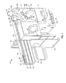
- FIG. 1 is a perspective illustration of a plug-in module system 1.
- the plug-in module system 1 comprises in this case a top hat rail 19 which is fastened in a housing (not shown) of a distribution box.
- a first holder 10 is fastened to the top hat rail 19 at a right angle.
- a second holder (not shown) is conventionally also arranged on the top hat rail 19.
- the two holders 10 surround and fasten a distributing bus bar 20 which is arranged parallel to the top hat rail 19 and has a plurality of power strips 22 which are isolated from one another by separating strips 23.
- An electrical component 17, which has a connection strip 18 for connecting an electric motor, for example, is also fastened to the top hat rail 19.
- a first connector module 13 is arranged on the distributing bus bar 20 at the level of the electrical component 17.
- a second connector module 21 is fastened to the distributing bus bar 20.
- the two connector modules 13, 21 each have a rotary knob 16 with a rotary closure 2 and a marking 11.
- the marking 11 includes an opened (I) and a closed state (II) of the rotary closure 2.
- the first connector module 13 further comprises a plurality of laterally outgoing cable openings 12 and also a plurality of associated openings 86 arranged at right angles at an upper side of a first cover 89. Cables (not shown), which are fastened in the first connector module 13 via screwing elements (not shown), are guided into the first connector module 13 through the cable openings 12. The further openings 86 allow access to the screwing elements without opening or closing the connector module 13 using a tool.
- the first cover 89 of the first connector module 13 is fastened to a first housing 90 by means of interlocking elements 15 which engage with interlocking openings 88.
- the first connector module 13 is connected backward to the distributing bus bar 20 and feeds the current from the cables into the individual power strips 22 via first electrical plug-in contacts. Furthermore, the first connector module 13 connects the electrical component 17 to the distributing bus bar 20 via the first and second plug-in contacts.
- the second plug-in contacts are plugged into contact sockets of the electrical component.
- the second connector module 21 can be connected to a second electrical component (not shown) in order in this way to tap the current from the distributing bus bar 20 and to conduct it to the second electrical component (not shown).
- the first plug-in contacts are plugged into the distributing bus bar 20.
- the second plug-in contacts are plugged into the contact sockets of the electrical component and connect the first plug-in contacts to the electrical component.
- the rotary knob 16 which both connector modules 13, 21 have, serves to fasten the connector modules 13, 21 to the distributing bus bar 20 and the electrical component 17 by means of a latching bolt (not shown).
- FIG. 2 is an exploded illustration of the first connector module 13.
- the first connector module 13 comprises the rotary knob 16 on which a latching bolt 30 is arranged.
- a first axial contact face 61 of the rotary knob 16 is associated with the first cover 89 of the first connector module 13.
- the first cover 89 has in this case at its underside a plurality of cover elements 920 which protrude into the first housing 90.
- the first housing 90 has current guides 80, 82, 84 of different lengths which are arranged in mutually separated regions of different lengths of the first housing 90.
- first guide elements 99 are arranged at an underside of the first housing 90 for engaging with the power strips 22 in order to facilitate the introduction of the first connecting elements 91 into the power strips 22 and to establish an electrical contact between the power strip 22 and the current guide 80, 82, 84.
- the first connecting element 91 is embodied in this case for example in a U-shaped manner.
- the current guides 80, 82, 84 are each connected at one end to a second connecting element 81.
- the first connecting element 91 is arranged with a clamping element 83 and the associated screwing element 85. Both the first connecting element 91 and the second connecting element 81 protrude on the underside from the first housing 90.
- the clamping elements 83 serve to receive the cable (not shown), the cables being fastened in the clamping element 83 by the screw 85.
- the current introduced via the cables is forwarded to the power strips 22 shown in Figure 1 of the distributing bus bar 20 by means of the first connecting elements 91.
- the first connecting elements 91 are plugged into one or more power strips 22.
- the current is also conducted by means of the second connecting elements 81 to the electrical component 17 connected thereto via the current guide 80, 82, 84.
- the current guides 80, 82, 84 have flat rails.
- Figure 3 is an exploded view drawing of the connector module 13 in the partly assembled state.
- the current guides 80, 82, 84 are fastened to the floor of the first housing 90 by means of a plurality of fastening holders 105.
- the latching bolt 30 is arranged centrally in the first housing 90.
- the latching bolt 30 has an annular stop 33.
- the latching bolt 30 is guided through an opening in the floor of the first housing 90 and rests, with a first abutment face of the stop 33, against a bearing face 98 on the floor of the first housing 90.
- the housing 90 has on its side faces a plurality of interlocking elements 15 which engage with corresponding interlocking openings 88 on the first cover 89.
- the current guides 80, 82, 84 are additionally fastened in the first housing 90 by the interlocking of the first cover 89 by means of cover elements 920 arranged at the underside of the housing cover 89.
- the grading of the individual current guides 80, 82, 84 in their length results from the engagement of the connecting elements 91 of the current guides 80, 82, 84 with the different power strips 22 of the distributing bus bar 20.
- the first cover 89 has a through-opening 97 having a circular circumferential contour 94.
- Two rectangular recesses 92, 95 are provided at opposing sides of the circumferential contour 94.
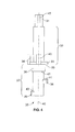
- Figure 4 is a side view of the latching bolt 30.
- the latching bolt 30 is divided substantially into an upper portion 32 and a lower portion 37 which are separated by the annular stop 33 which radially surrounds the latching bolt 30.
- the stop 33 has a larger diameter than the upper and lower portions 32, 37.
- a square 31 is formed at the upper axial end of the latching bolt 30 for a form-fitting connection with the rotary knob 16. Shapes other than a square are in this case also conceivable for a form-fitting connection, for example a splined profile, a polygonal profile or a serrated profile.
- a first web 45 is also arranged on the square 31 on a side face in the axial direction.
- a first abutment face 35 which is axially adjoined by a centring collar 36, is arranged in the lower portion 37 of the latching bolt 30 at the underside of the stop 33.
- the centring collar 36 is set back from the remainder of the lower portion 37 of the latching bolt 30 by means of a shoulder 42.
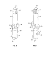
- FIG. 5 and Figure 6 are various perspective views of the latching bolt 30.
- the latching bolt 30 has at the lower end of the upper portion 32 on the stop 33 a plurality of locking cams 34, 40 which are radially offset from one another by about 90°.
- the two locking cams 34, 40 extend in this case axially along a part of the upper portion 32.
- Two engagement elements 38, 39 are also arranged in the lower portion 37.
- the first engagement element 38 is in this case radially offset by about 180° from the second engagement element 39 about an axis of rotation 46 of the connecting bolt 30.
- the two engagement elements 38, 39 are arranged on the latching bolt 30 at a different axial height.
- the two engagement elements 38, 39 each have a first or second fastening face 43, 44 which is arranged at the upper side of the two engagement elements 38, 39. It is also conceivable to arrange the two engagement elements 38, 39 at the same height or at a different angle to each other.
- FIG. 7 is a side view of the rotary knob 16.
- the rotary knob 16 has in this case a gripping face 60 which is embodied in an elongate manner perpendicularly to the axis of rotation 46 in order to make it easier for an operator to turn the rotary knob 16.
- the gripping face 60 also has an indentation for a good grip when detaching the connector module 13, 21. Adjoining the gripping face 60, there follows a plate-shaped region 70 having a diameter larger than that of an adjoining cylindrical portion 64.
- the plate-shaped region 70 has on an underside the contact face 61 as an axially arranged face which axially demarcates the plate-shaped region 70 from the cylindrical portion 64.
- a stop stud 66 is also arranged on the contact face 61 in order to restrict the range of rotation of the rotary knob 16 with further abutment faces 93, 930 on the cover 89, 901.
- Two opposing latching elements 62, 65 which each have a latching face 63 and are associated with the opposing first contact face 61, are arranged at an axial end of the cylindrical portion 64.
- Figure 8 is a plan view from below onto the rotary knob 16.
- the cylindrical portion 64 of the rotary knob 16 comprises on its axial end face a retainer 67 with a groove 68.
- the retainer 67 is in this case designed to receive the square 31 for a form-fitting connection of the latching bolt 30.
- the first web 45 of the latching bolt 30 engages with the groove 68 in the retainer 67 so that the rotary knob 16 is oriented in relation to the latching bolt 30 and can assume only one defined position in relation to the latching bolt 30.
- Figure 9 is a perspective view of the rotary knob 16.
- the gripping face 60 has at an outer radial region a pointer 71 which is designed to indicate the various positions of the rotary knob 16 by pointing to the marking 11 on the cover 89, 901 of the connector module 13,21.
- Figure 10 shows a detail in a plan view onto a region of the rotary closure 2 of the first cover 89.
- the region of the rotary closure 2 is embodied in the same way both on the first cover 89 of the first connector module 13 and on the second cover 901 of the second connector module 21.
- the roughly centrally positioned rotary closure 2 has the through-opening 97 with the circumferential contour 94.
- the circumferential contour 94 is divided into two opposing semicircular portions which are separated from each other by two rectangular recesses 92, 95 which are arranged opposing each other.
- the marking 11 for an opening position 120 (I) and a latching position 121 (II) is applied to the first cover 89.
- the region of rotation 112 is delimited on the right-hand side by a second abutment face 93.
- the second abutment face 93 protrudes in this case somewhat from the surface of the region of rotation 112, its side faces being arranged perpendicularly to the surface of the first cover 89.
- a stop element 96 is arranged in the region of rotation 112.
- the stop element 96 is shown in Figure 11 in section along a sectional plane A-A.
- Figure 11 is a sectional view of the sectional plane A-A shown in Figure 10 .
- a part of the rotary knob 16 is also depicted in addition to the first cover 89.
- the stop element 96 has a cross section of a right-angled triangle, a third abutment face 930 being arranged perpendicularly to the surface of the first cover 89.
- the hypotenuse is formed as an oblique sliding face 59.
- the region of rotation 112 of the rotary knob 16 is restricted by the two abutment faces 93, 930.
- the rotary knob 16 is turned in the clockwise direction in order to move the rotary knob 16 from the assembly position into the working region between the direction of rotation means 11.
- the stop stud 66 of the rotary knob 16 slides over the obliquely arranged sliding face 59 of the stop element 96.
- the increase associated therewith in the area of contact 61 with the first cover 89 is accommodated via elastic deformation of the two latching elements 62, 65. If the rotary knob 16 is turned further, the first contact face 61 rests again, after exceeding the maximum height of the stop element 96, against the first cover 89.
- Figure 12 shows a detail of the first cover 89 in a plan view in an assembly position.
- the rotary closure 2 is attached to the second cover 901 just as it is to the first cover 89.
- the rotary knob 16 is located, in an assembly position, turned out of the actual region of rotation 112 of the rotary knob 16 by about 45°. This position is necessary in order to allow the two latching elements 62, 65 of the rotary knob 16 to be guided through the two recesses 92, 95 in the first cover 89.
- the rotary knob 16 is guided into the actual region of rotation 112 between the marking 11 for the opening position 120 and the latching position 121.
- FIG 13 is a perspective illustration of the second cover 901 of the connector module 21.
- both the second cover 901 and the rotary knob 16 are illustrated viewed from below.
- the second cover 901 has in this case a third fastening face 113 which is arranged around the through-opening 97. If the rotary knob 16 is guided, in the assembly position, through the through-opening 97 using the two latching elements 62, 65, then the rotary knob 16 can be fastened to the second cover 901 by turning. In this case, the two latching elements 62, 65 engage behind the second cover 901 and fasten the rotary knob 16 as a result of the latching faces 63 resting against the third fastening face 113.
- the latching faces 63 rest against the third fastening face 113, they are not braced in order to allow the rotary knob 16 to turn from the opening position 120 to the latching position 121.
- the latching elements 62, 65 engage behind the cover in order to fasten the rotary knob 16 to the first cover 89.
- the first cover 89 of the first connector module 13 is embodied in the same manner as the second cover 901 in relation to the through-opening and the fastening of the rotary knob 16.
- Six holding-down means 103 are provided on the inner side of the cover 901, two respective holding-down means 103 being provided to press down a current guide 80, 82, 84.
- Figure 14 is a plan view onto a second housing 900 of the connector module 21 according to a second embodiment.
- the current guides and also the contacts thereof, the latching bolt 30 and further components are not shown in the second housing 900.
- a resilient interlocking 101 with a locking spring 111 which is fastened on one side to the housing 900 by means of the locking spring fastening 106, is arranged at the through-opening 97.
- the locking spring 111 has two elevations 108 which together form a well 109 in which a locking cam 34, 40 of the latching bolt 30 can engage in the latching position 121 or the opening position 120.
- the resilient interlocking 101 it is also possible to provide other locking means which allow interlocking of the latching bolt 30 in the latching position 121 or the opening position 120.
- the second housing 900 also has on the floor the bearing face 98 which serves the latching bolt 30 as an abutment face as a first axial bearing face.
- the first housing 90 of the first connector module 13 is embodied identically to the second housing 900 in relation to the bearing arrangement and the interlocking of the latching bolt.
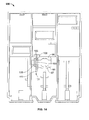
- Figure 15 is a plan view onto the second connector module 21 with built-in components.
- the components described in this case have the same functions as for the first connector module 13.
- the current guides 80, 82, 84 are fastened in the second housing 900 by means of the fastening holders 105.
- the latching bolt 30 is arranged on the bearing face 98.
- the latching bolt 30 issues again in this case at the underside of the second housing 900.
- the resilient interlocking 101 for defining the opening position 120 and the latching position 121 is brought about by one of the two locking cams 34, 40 engaging in the resilient interlocking 101 or in the well 109 therein.
- the orientation of the locking cams 34, 40 corresponds in this case to the opening position 120 or the latching position 121, so the rotary closure 2 can interlock in one of the two positions and cannot become automatically detached, for example as a result of vibrations.
- the latching bolt 30 can reversibly engage in the interlocking 101.
- the second housing 900 also has, for fastening the electrical component 17, a dovetail opening 100 with which the corresponding dovetail of the electrical component 17 engages.
- the latching bolt 30 is secured in an axial direction as a result of the first abutment face 35 and the bearing face 98.
- the second securing is carried out as a result of the connection of the latching bolt 30 to the rotary knob 16 and the second cover 901.
- Figure 16 is a perspective view from below of the second connector module 21.
- the latching bolt 30 of the rotary closure 2 protrudes from an underside 134 in the central position.
- the latching bolt 30 and also the rotary knob 16 are in the latching position 121.
- the first guide elements 99 for a respective bus bar 22 are arranged in a first partial region of the underside 134 of the housing 900.
- Each first guide element 99 comprises in this case a first connecting element 91 which at least partly surrounds the power strip.
- a respective second guide element 135 is associated with each first guide element 99 in order to facilitate orientation for plugging-on the second connector module 21 in relation to the bus bar 20.
- the side faces of the guide elements 99, 135 rest against the side faces of the separating strips 23 and guide the second connector module 21 during plugging-on. At least one direction of displacement is defined by the two guide elements 99, 135.
- a plurality of second connecting elements 81 are arranged in an edge region of the underside 134 toward a side face of the second housing 900.
- the second connecting elements are in this case axially surrounded by a closure element 130 in a partial region.
- Two plate-shaped third guide elements 131 which protrude beyond an obliquely arranged side face of the housing 900, are also arranged in the corner region of the side face of the housing 900.
- the third guide elements 131 each have on their outwardly directed side faces a fourth abutment face 132.
- the obliquely arranged side face is inclined in relation to the opposing side face arranged at right angles to the surface of the cover 901, so a first obliquely extending housing face 133 is formed on the second guide elements 131.
- the first connector module 13 has the same construction as the second connector module 21.
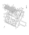
- Figure 17 is a perspective view of the plug-in module system 1.
- two holders 10, between which two electrical components 17 are arranged are fastened to the top hat rail 19.
- the two holders 19 serve to fasten the distributing bus bar 20.
- a first connector module 13 is arranged on the distributing bus bar 20 for feeding current into the distributing bus bar 20.
- the first connector module 13 is in this case merely plugged-on, but not latched by means of the rotary closure 2 to the first electrical component 17 and the distributing bus bar 20.
- No connector module is arranged on the second electrical component 17.
- the two electrical components 17 have the connection strip 18 for connecting further electrical components.
- the electrical component 17 is contacted via a connection region 170 which is arranged opposite the connection strip 18 and is concealed in the first electrical component 17 by the first connector module 13.
- the electrical component 17 has in the connection region 170 a plurality of contact openings 175 on a surface 177.
- a respective slot 174 as well as a second web172 are also arranged on the surface 177 at right angles to the distributing bus bar 20 in the region of the side faces of the electrical component 17.
- the dovetail 176 is arranged centrally between the two second webs 172 on the side face facing the distributing bus bar.
- One of the two connector modules 13, 21 can be used to connect the electrical component 17 to the distributing bus bar 20.
- the second connecting elements 81 of the connector module 13, 21 engage with the contact openings 175 and contact in the electrical component 17 contact sockets (not shown).
- the contact openings 175 are closed by the closure elements 130 in order in this way to prevent moisture from seeping into the electrical component 17, for example.
- the connector module 13, 21 engages with a slot 174 using the second respective guide element 131. Furthermore, the dovetail 176 engages with the dovetail opening 100 on the side face of the connector module 13, 21. These two engagements each define two possible directions of displacement of the connector module 13, 21.
- the abutment of the fourth abutment faces 132 against the second webs 172 prevents a displacement of the connector module 13, 21 parallel to the distributing bus bar 20.
- the first obliquely extending housing face 133 helps, together with the corresponding, likewise obliquely extending second housing face 171 of the second web 172, to make it easier to find the plug-on position of the connector module 13, 21.
- the underside 134 of the connector module 13, 21 rests on the surface 177 of the connection region 170 in the assembled state. Furthermore, the underside 134 rests in the region of the first guide elements 99 against an upper side 23 of the distributing bus bar 22.
- FIG 18 is a side view of the plug-in module system 1 with a partial section in the region of the rotary closure 2.
- the electrical component 17 is fastened to the top hat rail 19 by means of two top hat rail holders 190.
- the electrical component 17 may for example be an overload protector for an electric motor.
- an electric motor or a contactor can be connected to the connection strip 18 of the electrical component 17.
- a different module instead of the electrical component 17.
- the other module is also fastened to the top hat rail and has a first engagement opening 122.
- first connector module 13 will be described hereinafter, the first connector module can also be replaced by the second connector module 21 or by a different module. What matters is that the fastening is carried out by means of the plug-in module system 1 described hereinafter.
- the two connector modules 13, 21 are in this case regarded as being equivalent.
- the electrical component 17 is fastened to the top hat rail 19 by means of a top hat rail holder 190.
- the holder 10 for fastening the distributing bus bar 20 is likewise arranged on the top hat rail 19.
- the distributing bus bar serves to distribute the electrical current to the individual electrical components 17 by means of the bus bars 22.
- the electrical connection between the distributing bus bar 20 and the electrical component 17 is produced by means of the first connector module 13.
- the first connector module 13 also serves, in relation to the second connector module 21, to feed electrical current into the distributing bus bar 20.
- the second connector module 21 serves merely to connect an electrical component to the distributing bus bar 20.
- both the first connector module 13 and the second connector module 21 have the rotary closure 2 with the rotary knob 16 and the latching bolt 30.
- the first connector module 13 is plugged in the opening position 120 onto the distributing bus bar and the electrical component.
- the second connecting elements 81 establish an electrical contact to the electrical component 17, whereas the first connecting elements 91 partly surround the bus bars 22.
- the distributing bus bar 20 is connected to the electrical component 17 via the current guides 80, 82, 84.
- the latching bolt 30 is mounted on its centring collar 36 with which a first guide hole 124 is associated in the housing 90.
- the second radial mounting is carried out via the rotary knob 16, the cylindrical portion 64 of which is guided through a second guide hole 78 in the first cover 89 of the first connector module 13.
- the second possible axial direction of displacement of the latching bolt 30 over the square 31 and the retainer 76 is also defined as a result of the fact that the rotary knob 16 engages behind the first cover 89 using the latching elements 62, 65.
- the electrical component 17 has a first engagement opening 122 and the distributing bus bar 20 has a second engagement opening 123.
- the first engagement opening 122 also has a fourth fastening face 126.
- the second engagement opening 123 has a fifth fastening face 125.
- the first connector module 13, like the second connector module 21, is assembled in that the latching bolt 30 is introduced into the first housing 90 in the assembly position of the rotary knob 16.
- the first housing 90 is closed by means of the first cover 89 and subsequently the rotary knob 16 is placed onto the latching bolt 30 in the assembly position. Subsequently, the rotary knob 16 is turned through 45° in the clockwise direction, the rotary knob 16 latching on the first cover 89 in the opening position 120.
- the connector module 13 is fastened by turning the rotary knob 16 into the latching position 121.
- the latching bolt 30 is turned by means of the rotary knob 16 once it has been introduced through the through-opening 97, then its two engagement elements 38, 39 engage, as operative elements, with the engagement openings 122, 123 in the electrical component 17 or the connecting bar 20.
- the two engagement elements 38, 39 latch the first connector module 13 in that the fastening faces 125, 126 rest against the fastening faces 43, 44.
- the rotary knob 16 is turned from the latching position 121 (II) into the opening position 120 (I) in the region of rotation 112.
- the two engagement elements 38, 39 unlatch the connector module 13.
- the connector module 13 can be detached from the distributing bus bar 20 via the rotary knob 16 in the opening position 120. This has the advantage that disassembly is carried out promptly and without potential damage.
- the connector module 13 can afterwards be reassembled in the reverse order.
Landscapes
- Connector Housings Or Holding Contact Members (AREA)
Abstract
Description
- The invention relates to a connector module for electrically connecting an electrical component to a distributing bus bar, wherein the connector module has a rotary closure comprising operative elements which fasten the connector module to the distributing bus bar and the electrical component.
- Conventionally, industrial installations in distribution boxes are connected to a power supply, control technology or safety technology. Numerous systems are known for this purpose. In this case, individual electrical components, for example a switching module, a contactor or an overload module, are fastened in the distributor housing by means of a top hat rail. In order to electrically connect the electrical components to one another, the modules are connected to one another by cables or to a current-carrying distributing bus bar.
- The object of the invention is to rapidly and reliably connect the electrical components to the current-carrying distributing bus bar.
- This object is achieved by a connector module according to
claim 1 and by a plug-in module system according toclaim 15. Preferred embodiments are specified in the dependent claims. - According to the invention, it has been found that the electrical component can be rapidly and reliably connected to be distributing bus bar by means of a connector module. In this case, the connector module has a rotary closure with operative elements which fasten the connector module to the distributing bus bar and the electrical component.
- This has the advantage that the electrical component does not have to be connected to the power supply by means of manual installation of cables. Thus, errors in the installation of the cables can be virtually ruled out and the assembly but also the disassembly of the connector module can be rapidly brought about.
- In one embodiment of the invention, the rotary closure has a latching bolt with at least two engagement elements as operative elements which each engage with an engagement opening in the distributing bus bar and the electrical component. In this way, the connector module can be reliably fastened to the distributing bus bar and the electrical component.
- In one embodiment of the invention, the latching bolt has at least one locking cam which is associated with a resilient interlocking of the connector module. In this way, accidental turning of the rotary closure from a defined position can be avoided.
- In a further embodiment of the invention, the latching bolt has a bearing face which at least partly radially surrounds the latching bolt and is associated with an inner bearing face of the connector module. In this way, an axial end position of the latching bolt can easily be defined in one direction.
- In one embodiment of the invention, a rotary knob is pluggably arranged at a first axial end of the latching bolt, the engagement elements being arranged opposite the rotary knob at a second axial end of the latching bolt and releasing the connector module as a function of their rotational position. In this way, the latching bolt of the connector module can be actuated without a tool with the aid of the rotary knob.
- In a further embodiment of the invention, the rotary knob has at least one latching element which is arranged on a circumferential face of a cylindrical portion of the rotary knob and is designed to engage behind the cover of the connector module during turning of the rotary knob from an assembly position and to fasten the rotary knob to the cover. The cover is connected to the housing of the connector module, so in this way the connector module can be detached from the distributing bus bar and the electrical component by pulling on the rotary knob in an unlatched position of the latching bolt.
- In a further embodiment of the invention, the rotary knob has at least one stop stud which is arranged radially to the axis of rotation of the rotary knob and which is associated with an abutment face on the cover of the connector module. In this way, accidental turning into an undesired position of the rotary knob can be reliably avoided.
- In a further embodiment of the invention, a stop element is arranged on the cover of the connector module, the stop stud sliding over the stop element in one direction of rotation of the rotary knob and blocking turning of the rotary knob in the opposite direction. This has the advantage that turning of the rotary knob back into an assembly position is prevented.
- In a further embodiment of the invention, the rotary knob has a retainer for the latching bolt, the retainer and also the axial end of the latching bolt being embodied as a form-fitting connection in relation to a rotational movement. In this way, the latching bolt can be turned by turning the rotary knob.
- In a further embodiment of the invention, the axial end of the latching bolt has, in the region of the form-fitting connection on a side face of the latching bolt, a web which engages with a groove in the retainer. In this way, the orientation of the latching bolt to the rotary knob can be reliably defined.
- In a further embodiment of the invention, the rotary knob has at least one gripping face which is embodied in an elongate manner and protrudes beyond the diameter of the cylindrical portion. In this way, the orientation of the latching bolt can be indicated to the operator.
- In a further embodiment of the invention, the connector module has at an underside at least one closure element which closes a contact opening in the electrical component, through which a connecting element is guided. In this way, infiltration of moisture or dirt at the contact opening into the electrical component can be avoided.
- In a further embodiment of the invention, at least one connecting element, which is at least partly surrounded by a first guide element, is arranged at the underside of the connector module. In this way, plugging of the connecting element into a distributing bus bar by means of the first guide element can be facilitated.
- In a further embodiment of the invention, a second guide element, which engages with a slot in the electrical component, is arranged on the connector module on a side face of the housing. In this way, the connector module can be secured in relation to the electrical component in two directions of displacement.
- In a further embodiment of the invention, the second guide element has a third abutment face which is arranged at right angles to the distributing bus bar and is associated with a fourth abutment face of the electrical component. In this way, displacement of the connector module parallel to the distributing bus bar can be prevented.
- In a further embodiment of the invention, the connector module has a first obliquely arranged housing face with which a second obliquely arranged housing face of the electrical component is associated. In this way, plugging of the connector module onto the electrical component can be facilitated in that the two oblique housing faces guide the connector module into the plug-in position.
- The invention will be described hereinafter in greater detail with reference to the drawings, in which:
-
Figure 1 is a perspective illustration of a plug-in module system; -
Figure 2 is an exploded illustration of a first connector module according to a first embodiment; -
Figure 3 is an exploded illustration of the first connector module shown inFigure 2 in the partly assembled state; -
Figure 4 is a side view of a latching bolt; -
Figure 5 and Figure 6 are various perspective views of the latching bolt; -
Figure 7 is a side view of a rotary knob; -
Figure 8 is a plan view onto the rotary knob; -
Figure 9 is a perspective view of the rotary knob; -
Figure 10 shows a detail in a plan view onto a region of a rotary closure; -
Figure 11 is a sectional view of the connector module taken along the sectional plane A-A shown inFigure 10 ; -
Figure 12 is a plan view of a detail of a cover in the assembly position; -
Figure 13 is a slightly perspective illustration of the cover of the second connector module; -
Figure 14 is a plan view onto a housing of the second connector module; -
Figure 15 is a plan view onto the second connector module with built-in components; -
Figure 16 is a perspective view from below of the second connector module; -
Figure 17 is a perspective view of the plug-in module system; and -
Figure 18 is a side view with a partial section of the plug-in module system. -
Figure 1 is a perspective illustration of a plug-inmodule system 1. The plug-inmodule system 1 comprises in this case atop hat rail 19 which is fastened in a housing (not shown) of a distribution box. Afirst holder 10 is fastened to thetop hat rail 19 at a right angle. For reasons of stability, a second holder (not shown) is conventionally also arranged on thetop hat rail 19. The twoholders 10 surround and fasten a distributingbus bar 20 which is arranged parallel to thetop hat rail 19 and has a plurality ofpower strips 22 which are isolated from one another by separatingstrips 23. Anelectrical component 17, which has aconnection strip 18 for connecting an electric motor, for example, is also fastened to thetop hat rail 19. Afirst connector module 13 is arranged on the distributingbus bar 20 at the level of theelectrical component 17. In addition to thefirst connector module 13, asecond connector module 21 is fastened to the distributingbus bar 20. The twoconnector modules rotary knob 16 with arotary closure 2 and a marking 11. The marking 11 includes an opened (I) and a closed state (II) of therotary closure 2. - The
first connector module 13 further comprises a plurality of laterallyoutgoing cable openings 12 and also a plurality of associatedopenings 86 arranged at right angles at an upper side of afirst cover 89. Cables (not shown), which are fastened in thefirst connector module 13 via screwing elements (not shown), are guided into thefirst connector module 13 through thecable openings 12. Thefurther openings 86 allow access to the screwing elements without opening or closing theconnector module 13 using a tool. Thefirst cover 89 of thefirst connector module 13 is fastened to afirst housing 90 by means of interlockingelements 15 which engage with interlockingopenings 88. - Power is supplied into the plug-in
module system 1 by means of the cables connected via thecable openings 12. Thefirst connector module 13 is connected backward to the distributingbus bar 20 and feeds the current from the cables into theindividual power strips 22 via first electrical plug-in contacts. Furthermore, thefirst connector module 13 connects theelectrical component 17 to the distributingbus bar 20 via the first and second plug-in contacts. The second plug-in contacts are plugged into contact sockets of the electrical component. Like thefirst connector module 13, thesecond connector module 21 can be connected to a second electrical component (not shown) in order in this way to tap the current from the distributingbus bar 20 and to conduct it to the second electrical component (not shown). For this purpose, the first plug-in contacts are plugged into the distributingbus bar 20. The second plug-in contacts are plugged into the contact sockets of the electrical component and connect the first plug-in contacts to the electrical component. - The
rotary knob 16, which bothconnector modules connector modules bus bar 20 and theelectrical component 17 by means of a latching bolt (not shown). -
Figure 2 is an exploded illustration of thefirst connector module 13. Thefirst connector module 13 comprises therotary knob 16 on which alatching bolt 30 is arranged. A firstaxial contact face 61 of therotary knob 16 is associated with thefirst cover 89 of thefirst connector module 13. Thefirst cover 89 has in this case at its underside a plurality ofcover elements 920 which protrude into thefirst housing 90. Thefirst housing 90 hascurrent guides first housing 90. Furthermore, correspondingfirst guide elements 99 are arranged at an underside of thefirst housing 90 for engaging with the power strips 22 in order to facilitate the introduction of the first connectingelements 91 into the power strips 22 and to establish an electrical contact between thepower strip 22 and thecurrent guide element 91 is embodied in this case for example in a U-shaped manner. - The current guides 80, 82, 84 are each connected at one end to a second connecting
element 81. At the end of the current guides 80, 82, 84 that opposes the second connectingelement 81, the first connectingelement 91 is arranged with a clampingelement 83 and the associated screwingelement 85. Both the first connectingelement 91 and the second connectingelement 81 protrude on the underside from thefirst housing 90. The clampingelements 83 serve to receive the cable (not shown), the cables being fastened in the clampingelement 83 by thescrew 85. - The current introduced via the cables is forwarded to the power strips 22 shown in
Figure 1 of the distributingbus bar 20 by means of the first connectingelements 91. For this purpose, the first connectingelements 91 are plugged into one or more power strips 22. Furthermore, the current is also conducted by means of the second connectingelements 81 to theelectrical component 17 connected thereto via thecurrent guide -
Figure 3 is an exploded view drawing of theconnector module 13 in the partly assembled state. In thefirst housing 90, the current guides 80, 82, 84 are fastened to the floor of thefirst housing 90 by means of a plurality offastening holders 105. The latchingbolt 30 is arranged centrally in thefirst housing 90. The latchingbolt 30 has anannular stop 33. The latchingbolt 30 is guided through an opening in the floor of thefirst housing 90 and rests, with a first abutment face of thestop 33, against a bearingface 98 on the floor of thefirst housing 90. In order to reliably close thefirst housing 90, thehousing 90 has on its side faces a plurality of interlockingelements 15 which engage with corresponding interlockingopenings 88 on thefirst cover 89. Furthermore, the current guides 80, 82, 84 are additionally fastened in thefirst housing 90 by the interlocking of thefirst cover 89 by means ofcover elements 920 arranged at the underside of thehousing cover 89. The grading of the individualcurrent guides elements 91 of the current guides 80, 82, 84 with thedifferent power strips 22 of the distributingbus bar 20. - Furthermore, the
first cover 89 has a through-opening 97 having a circularcircumferential contour 94. Tworectangular recesses circumferential contour 94. -
Figure 4 is a side view of the latchingbolt 30. The latchingbolt 30 is divided substantially into anupper portion 32 and alower portion 37 which are separated by theannular stop 33 which radially surrounds the latchingbolt 30. Thestop 33 has a larger diameter than the upper andlower portions bolt 30 for a form-fitting connection with therotary knob 16. Shapes other than a square are in this case also conceivable for a form-fitting connection, for example a splined profile, a polygonal profile or a serrated profile. Afirst web 45 is also arranged on the square 31 on a side face in the axial direction. - A
first abutment face 35, which is axially adjoined by acentring collar 36, is arranged in thelower portion 37 of the latchingbolt 30 at the underside of thestop 33. Thecentring collar 36 is set back from the remainder of thelower portion 37 of the latchingbolt 30 by means of ashoulder 42. -
Figure 5 and Figure 6 are various perspective views of the latchingbolt 30. In this case, the latchingbolt 30 has at the lower end of theupper portion 32 on the stop 33 a plurality of lockingcams locking cams upper portion 32. Furthermore, it is also conceivable to arrange the lockingcams - Two
engagement elements lower portion 37. Thefirst engagement element 38 is in this case radially offset by about 180° from thesecond engagement element 39 about an axis ofrotation 46 of the connectingbolt 30. Furthermore, the twoengagement elements bolt 30 at a different axial height. The twoengagement elements second fastening face engagement elements engagement elements -
Figure 7 is a side view of therotary knob 16. Therotary knob 16 has in this case a grippingface 60 which is embodied in an elongate manner perpendicularly to the axis ofrotation 46 in order to make it easier for an operator to turn therotary knob 16. The grippingface 60 also has an indentation for a good grip when detaching theconnector module face 60, there follows a plate-shapedregion 70 having a diameter larger than that of an adjoiningcylindrical portion 64. The plate-shapedregion 70 has on an underside thecontact face 61 as an axially arranged face which axially demarcates the plate-shapedregion 70 from thecylindrical portion 64. Astop stud 66 is also arranged on thecontact face 61 in order to restrict the range of rotation of therotary knob 16 with further abutment faces 93, 930 on thecover elements face 63 and are associated with the opposingfirst contact face 61, are arranged at an axial end of thecylindrical portion 64. -
Figure 8 is a plan view from below onto therotary knob 16. Thecylindrical portion 64 of therotary knob 16 comprises on its axial end face aretainer 67 with agroove 68. Theretainer 67 is in this case designed to receive the square 31 for a form-fitting connection of the latchingbolt 30. Thefirst web 45 of the latchingbolt 30 engages with thegroove 68 in theretainer 67 so that therotary knob 16 is oriented in relation to the latchingbolt 30 and can assume only one defined position in relation to the latchingbolt 30. -
Figure 9 is a perspective view of therotary knob 16. The grippingface 60 has at an outer radial region apointer 71 which is designed to indicate the various positions of therotary knob 16 by pointing to the marking 11 on thecover connector module -
Figure 10 shows a detail in a plan view onto a region of therotary closure 2 of thefirst cover 89. The region of therotary closure 2 is embodied in the same way both on thefirst cover 89 of thefirst connector module 13 and on thesecond cover 901 of thesecond connector module 21. In this case, the roughly centrally positionedrotary closure 2 has the through-opening 97 with thecircumferential contour 94. Thecircumferential contour 94 is divided into two opposing semicircular portions which are separated from each other by tworectangular recesses first cover 89. A partly annular region ofrotation 112, which is sunk slightly from the surface of thefirst cover 89, is also arranged around a partial region around the through-opening 97. The region ofrotation 112 is delimited on the right-hand side by asecond abutment face 93. Thesecond abutment face 93 protrudes in this case somewhat from the surface of the region ofrotation 112, its side faces being arranged perpendicularly to the surface of thefirst cover 89. Furthermore, astop element 96 is arranged in the region ofrotation 112. Thestop element 96 is shown inFigure 11 in section along a sectional plane A-A. -
Figure 11 is a sectional view of the sectional plane A-A shown inFigure 10 . A part of therotary knob 16 is also depicted in addition to thefirst cover 89. Thestop element 96 has a cross section of a right-angled triangle, athird abutment face 930 being arranged perpendicularly to the surface of thefirst cover 89. The hypotenuse is formed as anoblique sliding face 59. - The region of
rotation 112 of therotary knob 16 is restricted by the two abutment faces 93, 930. Therotary knob 16 is turned in the clockwise direction in order to move therotary knob 16 from the assembly position into the working region between the direction of rotation means 11. In the region of thestop element 96, thestop stud 66 of therotary knob 16 slides over the obliquely arranged slidingface 59 of thestop element 96. The increase associated therewith in the area ofcontact 61 with thefirst cover 89 is accommodated via elastic deformation of the two latchingelements rotary knob 16 is turned further, thefirst contact face 61 rests again, after exceeding the maximum height of thestop element 96, against thefirst cover 89. Excessive turning of thestop element 96 is prevented in that thestop stud 66 strikes against the perpendicularly positionedthird abutment face 930. The perpendicular arrangement of thethird abutment face 930 prevents thestop stud 66 from being turned beyond thethird abutment face 930. -
Figure 12 shows a detail of thefirst cover 89 in a plan view in an assembly position. Therotary closure 2 is attached to thesecond cover 901 just as it is to thefirst cover 89. For assembly, therotary knob 16 is located, in an assembly position, turned out of the actual region ofrotation 112 of therotary knob 16 by about 45°. This position is necessary in order to allow the two latchingelements rotary knob 16 to be guided through the tworecesses first cover 89. In order to latch therotary knob 16 to thefirst cover 89, therotary knob 16 is guided into the actual region ofrotation 112 between the marking 11 for theopening position 120 and thelatching position 121. -
Figure 13 is a perspective illustration of thesecond cover 901 of theconnector module 21. In this case, both thesecond cover 901 and therotary knob 16 are illustrated viewed from below. Thesecond cover 901 has in this case athird fastening face 113 which is arranged around the through-opening 97. If therotary knob 16 is guided, in the assembly position, through the through-opening 97 using the two latchingelements rotary knob 16 can be fastened to thesecond cover 901 by turning. In this case, the two latchingelements second cover 901 and fasten therotary knob 16 as a result of the latching faces 63 resting against thethird fastening face 113. Although the latching faces 63 rest against thethird fastening face 113, they are not braced in order to allow therotary knob 16 to turn from theopening position 120 to thelatching position 121. On thefirst cover 89, as on thesecond cover 901, the latchingelements rotary knob 16 to thefirst cover 89. Thefirst cover 89 of thefirst connector module 13 is embodied in the same manner as thesecond cover 901 in relation to the through-opening and the fastening of therotary knob 16. Six holding-down means 103 are provided on the inner side of thecover 901, two respective holding-down means 103 being provided to press down acurrent guide
Figure 14 is a plan view onto asecond housing 900 of theconnector module 21 according to a second embodiment. The current guides and also the contacts thereof, the latchingbolt 30 and further components are not shown in thesecond housing 900. Aresilient interlocking 101 with alocking spring 111, which is fastened on one side to thehousing 900 by means of the lockingspring fastening 106, is arranged at the through-opening 97. The lockingspring 111 has twoelevations 108 which together form a well 109 in which alocking cam bolt 30 can engage in thelatching position 121 or theopening position 120. Instead of theresilient interlocking 101, it is also possible to provide other locking means which allow interlocking of the latchingbolt 30 in thelatching position 121 or theopening position 120. - The
second housing 900 also has on the floor the bearingface 98 which serves the latchingbolt 30 as an abutment face as a first axial bearing face. Thefirst housing 90 of thefirst connector module 13 is embodied identically to thesecond housing 900 in relation to the bearing arrangement and the interlocking of the latching bolt. -
Figure 15 is a plan view onto thesecond connector module 21 with built-in components. The components described in this case have the same functions as for thefirst connector module 13. The current guides 80, 82, 84 are fastened in thesecond housing 900 by means of thefastening holders 105. The latchingbolt 30 is arranged on the bearingface 98. The latchingbolt 30 issues again in this case at the underside of thesecond housing 900. Theresilient interlocking 101 for defining theopening position 120 and thelatching position 121 is brought about by one of the two lockingcams resilient interlocking 101 or in the well 109 therein. The orientation of the lockingcams opening position 120 or thelatching position 121, so therotary closure 2 can interlock in one of the two positions and cannot become automatically detached, for example as a result of vibrations. As a result of the one-sidedlocking spring fastening 106 and the formation of theresilient interlocking 101 with the lockingspring 111, the latchingbolt 30 can reversibly engage in theinterlocking 101. - The
second housing 900 also has, for fastening theelectrical component 17, adovetail opening 100 with which the corresponding dovetail of theelectrical component 17 engages. The latchingbolt 30 is secured in an axial direction as a result of thefirst abutment face 35 and the bearingface 98. The second securing is carried out as a result of the connection of the latchingbolt 30 to therotary knob 16 and thesecond cover 901. -
Figure 16 is a perspective view from below of thesecond connector module 21. In this case, the latchingbolt 30 of therotary closure 2 protrudes from anunderside 134 in the central position. The latchingbolt 30 and also therotary knob 16 are in thelatching position 121. Thefirst guide elements 99 for arespective bus bar 22 are arranged in a first partial region of theunderside 134 of thehousing 900. Eachfirst guide element 99 comprises in this case a first connectingelement 91 which at least partly surrounds the power strip. Furthermore, a respectivesecond guide element 135 is associated with eachfirst guide element 99 in order to facilitate orientation for plugging-on thesecond connector module 21 in relation to thebus bar 20. In this case, the side faces of theguide elements second connector module 21 during plugging-on. At least one direction of displacement is defined by the twoguide elements - In a second partial portion of the
second connector module 21, a plurality of second connectingelements 81 are arranged in an edge region of theunderside 134 toward a side face of thesecond housing 900. The second connecting elements are in this case axially surrounded by aclosure element 130 in a partial region. Two plate-shapedthird guide elements 131, which protrude beyond an obliquely arranged side face of thehousing 900, are also arranged in the corner region of the side face of thehousing 900. Thethird guide elements 131 each have on their outwardly directed side faces afourth abutment face 132. The obliquely arranged side face is inclined in relation to the opposing side face arranged at right angles to the surface of thecover 901, so a first obliquely extendinghousing face 133 is formed on thesecond guide elements 131. - On the underside, the
first connector module 13 has the same construction as thesecond connector module 21. -
Figure 17 is a perspective view of the plug-inmodule system 1. In this case, twoholders 10, between which twoelectrical components 17 are arranged, are fastened to thetop hat rail 19. The twoholders 19 serve to fasten the distributingbus bar 20. Afirst connector module 13 is arranged on the distributingbus bar 20 for feeding current into the distributingbus bar 20. Thefirst connector module 13 is in this case merely plugged-on, but not latched by means of therotary closure 2 to the firstelectrical component 17 and the distributingbus bar 20. No connector module is arranged on the secondelectrical component 17. The twoelectrical components 17 have theconnection strip 18 for connecting further electrical components. Theelectrical component 17 is contacted via aconnection region 170 which is arranged opposite theconnection strip 18 and is concealed in the firstelectrical component 17 by thefirst connector module 13. For this purpose, theelectrical component 17 has in the connection region 170 a plurality ofcontact openings 175 on asurface 177. Arespective slot 174 as well as a second web172 are also arranged on thesurface 177 at right angles to the distributingbus bar 20 in the region of the side faces of theelectrical component 17. Furthermore, thedovetail 176 is arranged centrally between the twosecond webs 172 on the side face facing the distributing bus bar. - One of the two
connector modules electrical component 17 to the distributingbus bar 20. For this purpose, the second connectingelements 81 of theconnector module contact openings 175 and contact in theelectrical component 17 contact sockets (not shown). Thecontact openings 175 are closed by theclosure elements 130 in order in this way to prevent moisture from seeping into theelectrical component 17, for example. - In order to define the position of the
connector module connector module slot 174 using the secondrespective guide element 131. Furthermore, thedovetail 176 engages with thedovetail opening 100 on the side face of theconnector module connector module second webs 172 prevents a displacement of theconnector module bus bar 20. The first obliquely extendinghousing face 133 helps, together with the corresponding, likewise obliquely extendingsecond housing face 171 of thesecond web 172, to make it easier to find the plug-on position of theconnector module - The
underside 134 of theconnector module surface 177 of theconnection region 170 in the assembled state. Furthermore, theunderside 134 rests in the region of thefirst guide elements 99 against anupper side 23 of the distributingbus bar 22. -
Figure 18 is a side view of the plug-inmodule system 1 with a partial section in the region of therotary closure 2. In this case, theelectrical component 17 is fastened to thetop hat rail 19 by means of two tophat rail holders 190. Theelectrical component 17 may for example be an overload protector for an electric motor. For this purpose, an electric motor or a contactor can be connected to theconnection strip 18 of theelectrical component 17. It is however conceivable to arrange a different module instead of theelectrical component 17. The important thing is that the other module is also fastened to the top hat rail and has afirst engagement opening 122. - Although the
first connector module 13 will be described hereinafter, the first connector module can also be replaced by thesecond connector module 21 or by a different module. What matters is that the fastening is carried out by means of the plug-inmodule system 1 described hereinafter. The twoconnector modules - The
electrical component 17 is fastened to thetop hat rail 19 by means of a tophat rail holder 190. Theholder 10 for fastening the distributingbus bar 20 is likewise arranged on thetop hat rail 19. The distributing bus bar serves to distribute the electrical current to the individualelectrical components 17 by means of the bus bars 22. The electrical connection between the distributingbus bar 20 and theelectrical component 17 is produced by means of thefirst connector module 13. In addition, thefirst connector module 13 also serves, in relation to thesecond connector module 21, to feed electrical current into the distributingbus bar 20. Thesecond connector module 21 serves merely to connect an electrical component to the distributingbus bar 20. For fastening, both thefirst connector module 13 and thesecond connector module 21 have therotary closure 2 with therotary knob 16 and the latchingbolt 30. - In order to establish an electrical connection between the
electrical component 17 and the distributingbus bar 20, thefirst connector module 13 is plugged in theopening position 120 onto the distributing bus bar and the electrical component. In this case, the second connectingelements 81 establish an electrical contact to theelectrical component 17, whereas the first connectingelements 91 partly surround the bus bars 22. The distributingbus bar 20 is connected to theelectrical component 17 via the current guides 80, 82, 84. - For turning the rotary closure, the latching
bolt 30 is mounted on itscentring collar 36 with which afirst guide hole 124 is associated in thehousing 90. The second radial mounting is carried out via therotary knob 16, thecylindrical portion 64 of which is guided through a second guide hole 78 in thefirst cover 89 of thefirst connector module 13. Furthermore, the second possible axial direction of displacement of the latchingbolt 30 over the square 31 and the retainer 76 is also defined as a result of the fact that therotary knob 16 engages behind thefirst cover 89 using the latchingelements - In order to fasten the
first connector module 13 to theelectrical component 17 and the distributingbus bar 22, theelectrical component 17 has afirst engagement opening 122 and the distributingbus bar 20 has asecond engagement opening 123. Thefirst engagement opening 122 also has afourth fastening face 126. Furthermore, the second engagement opening 123 has afifth fastening face 125. - The
first connector module 13, like thesecond connector module 21, is assembled in that the latchingbolt 30 is introduced into thefirst housing 90 in the assembly position of therotary knob 16. Thefirst housing 90 is closed by means of thefirst cover 89 and subsequently therotary knob 16 is placed onto the latchingbolt 30 in the assembly position. Subsequently, therotary knob 16 is turned through 45° in the clockwise direction, therotary knob 16 latching on thefirst cover 89 in theopening position 120. Theconnector module 13 is fastened by turning therotary knob 16 into thelatching position 121. If the latchingbolt 30 is turned by means of therotary knob 16 once it has been introduced through the through-opening 97, then its twoengagement elements engagement openings electrical component 17 or the connectingbar 20. The twoengagement elements first connector module 13 in that the fastening faces 125, 126 rest against the fastening faces 43, 44. - In order to disassemble the
first connector module 13 from theelectrical component 17 and also the distributingbus bar 20, therotary knob 16 is turned from the latching position 121 (II) into the opening position 120 (I) in the region ofrotation 112. As a result, the twoengagement elements connector module 13. As thefirst cover 89 is connected to thehousing 90 by the lockingelements connector module 13 can be detached from the distributingbus bar 20 via therotary knob 16 in theopening position 120. This has the advantage that disassembly is carried out promptly and without potential damage. Theconnector module 13 can afterwards be reassembled in the reverse order.
Claims (15)
- Connector module (13; 21) for electrically connecting an electrical component (17) to a distributing bus bar (20), wherein the connector module (13; 21) has a rotary closure (2) comprising operative elements (38, 39) which fasten the connector module (13; 21) to the distributing bus bar (20) and the electrical component (17).
- Connector module (13; 21) according to claim 1, wherein the rotary closure (2) comprises a latching bolt (30) having at least two engagement elements (38, 39) as operative elements which are designed each to engage with an engagement opening (122, 123) in the distributing bus bar (20) and the electrical component (17).
- Connector module (13; 21) according to claim 2, wherein the latching bolt (30) has at least one locking cam (34, 40) which is associated with a resilient interlocking (101) of the connector module (13; 21).
- Connector module (13; 21) according to either claim 2 or claim 3, wherein the latching bolt (30) has a first abutment face (93) which at least partly radially surrounds the latching bolt (30) and is associated with an inner bearing face (98) of the connector module (13; 21).
- Connector module (13; 21) according to any one of claims 2 to 4, wherein a rotary knob (16) is pluggably arranged at a first axial end of the latching bolt (30), the engagement elements (38, 39) being arranged opposite the rotary knob (16) at a second axial end of the latching bolt and releasing the connector module (13; 21) as a function of their rotational position.
- Connector module (13; 21) according to any one of claims 1 to 5, wherein the rotary knob (16) has at least one latching element (62, 65) which is arranged on a circumferential face of a cylindrical portion (64) of the rotary knob (16) and is designed to engage behind a cover (89; 901) of the connector module (13; 21) during turning of the rotary knob (16) and to fasten the rotary knob (16) to the cover (89; 901).
- Connector module (13; 21) according to claim 6, wherein the rotary knob (16) has at least one stop stud (66) which is arranged radially to an axis of rotation (46) of the rotary knob (16) and which is associated with at least a second abutment face (93, 930) on the cover (89; 901) of the connector module (13; 21).
- Connector module (13; 21) according to either claim 6 or claim 7, wherein a stop element (96) is arranged on a face of the cover (89; 901) of the connector module (13; 21), the stop element (96) being designed to have the stop stud (66) slide over the stop element in one direction of rotation of the rotary knob (16) and to block turning of the rotary knob (16) in the opposite direction.
- Connector module (13; 21) according to any one of claims 5 to 8, wherein a retainer (67) on the rotary knob (16) for the latching bolt (30) and also an axial end of the latching bolt (30) are embodied as a form-fitting connection (31, 67).
- Connector module (13; 21) according to any one of claims 5 to 9, wherein the rotary knob (16) has at least one gripping face (60) which is embodied in an elongate manner and protrudes beyond the diameter of a cylindrical portion (64).
- Connector module (13; 21) according to any one of claims 1 to 10, wherein the connector module (13; 21) has at an underside (134) at least one closure element (130) which is designed to close a contact opening (175) through which a connecting element (81) is guided.
- Connector module (13; 21) according to any one of claims 1 to 11, wherein at least one connecting element (81; 91), which is at least partly surrounded by a first guide element (99) for engaging with the distributing bus bar (20), is arranged on the connector module (13; 21) at the underside (134).
- Connector module (13; 21) according to any one of claims 1 to 12, wherein a second guide element (131), which is provided for engaging in a slot (174) in the electrical component (17), is arranged on a side face of the connector module (13; 21).
- Connector module (13; 21) according to claim 13, wherein the second guide element (131) has a third abutment face (132) which is associated with a fourth abutment face (172) of the electrical component (17).
- Plug-in module system (1) with a distributing bus bar (20) and an electrical component (17), wherein the electrical component (17) is connected to a connector module (13; 21) and is electrically connected and has a rotary closure (2) for latching the connector module (13; 21) to the distributing bus bar (20) and the electrical component (17), the rotary closure (2) having operative elements (38, 39) which engage with the distributing bus bar (20) and the electrical component (17).
Applications Claiming Priority (1)
| Application Number | Priority Date | Filing Date | Title |
|---|---|---|---|
| DE202009013181U DE202009013181U1 (en) | 2009-09-30 | 2009-09-30 | Connector module and plug-in module system |
Publications (1)
| Publication Number | Publication Date |
|---|---|
| EP2306591A1 true EP2306591A1 (en) | 2011-04-06 |
Family
ID=41413322
Family Applications (1)
| Application Number | Title | Priority Date | Filing Date |
|---|---|---|---|
| EP10176839A Withdrawn EP2306591A1 (en) | 2009-09-30 | 2010-09-15 | Connector module and plug-in module system |
Country Status (2)
| Country | Link |
|---|---|
| EP (1) | EP2306591A1 (en) |
| DE (1) | DE202009013181U1 (en) |
Cited By (3)
| Publication number | Priority date | Publication date | Assignee | Title |
|---|---|---|---|---|
| WO2015084246A1 (en) * | 2013-12-05 | 2015-06-11 | Moduel Ab | Electrical modules |
| WO2022115182A1 (en) * | 2020-11-25 | 2022-06-02 | Arris Enterprises Llc | Integral enclosure integration system |
| CN119542787A (en) * | 2025-01-23 | 2025-02-28 | 浙江桥架母线有限公司 | Bus conductive connecting device |
Citations (5)
| Publication number | Priority date | Publication date | Assignee | Title |
|---|---|---|---|---|
| EP0454016A2 (en) * | 1990-04-26 | 1991-10-30 | ABBPATENT GmbH | Mains clamp fixed on a standardized support rail |
| GB2310768A (en) * | 1996-01-31 | 1997-09-03 | Schneider Ltd | Distribution equipment for a wall mountable consumer unit |
| WO1998048496A1 (en) * | 1997-04-17 | 1998-10-29 | Totally Flexible Products Pty. Ltd. | Electrical bus connector apparatus and method |
| DE102005023452A1 (en) * | 2005-05-20 | 2006-11-23 | Siemens Ag | Mounting and wiring system for electrical function modules, especially for switchgear, has profile rail designed so electrical function module can be attached in any position in longitudinal direction of rail |
| DE202008004699U1 (en) * | 2008-04-03 | 2008-06-12 | Phoenix Contact Gmbh & Co. Kg | Fastening device for fastening pluggable electrical housing |
-
2009
- 2009-09-30 DE DE202009013181U patent/DE202009013181U1/en not_active Expired - Lifetime
-
2010
- 2010-09-15 EP EP10176839A patent/EP2306591A1/en not_active Withdrawn
Patent Citations (5)
| Publication number | Priority date | Publication date | Assignee | Title |
|---|---|---|---|---|
| EP0454016A2 (en) * | 1990-04-26 | 1991-10-30 | ABBPATENT GmbH | Mains clamp fixed on a standardized support rail |
| GB2310768A (en) * | 1996-01-31 | 1997-09-03 | Schneider Ltd | Distribution equipment for a wall mountable consumer unit |
| WO1998048496A1 (en) * | 1997-04-17 | 1998-10-29 | Totally Flexible Products Pty. Ltd. | Electrical bus connector apparatus and method |
| DE102005023452A1 (en) * | 2005-05-20 | 2006-11-23 | Siemens Ag | Mounting and wiring system for electrical function modules, especially for switchgear, has profile rail designed so electrical function module can be attached in any position in longitudinal direction of rail |
| DE202008004699U1 (en) * | 2008-04-03 | 2008-06-12 | Phoenix Contact Gmbh & Co. Kg | Fastening device for fastening pluggable electrical housing |
Cited By (5)
| Publication number | Priority date | Publication date | Assignee | Title |
|---|---|---|---|---|
| WO2015084246A1 (en) * | 2013-12-05 | 2015-06-11 | Moduel Ab | Electrical modules |
| US9774153B2 (en) | 2013-12-05 | 2017-09-26 | Moduel Ab | Electrical modules |
| WO2022115182A1 (en) * | 2020-11-25 | 2022-06-02 | Arris Enterprises Llc | Integral enclosure integration system |
| CN119542787A (en) * | 2025-01-23 | 2025-02-28 | 浙江桥架母线有限公司 | Bus conductive connecting device |
| CN119542787B (en) * | 2025-01-23 | 2025-04-11 | 浙江桥架母线有限公司 | A busbar conductive connection device |
Also Published As
| Publication number | Publication date |
|---|---|
| DE202009013181U1 (en) | 2009-12-10 |
Similar Documents
| Publication | Publication Date | Title |
|---|---|---|
| KR20210116249A (en) | lockout tagout assembly and system and method of using same | |
| US7189921B2 (en) | Housing arrangement with at least two junction boxes | |
| CN104348026B (en) | Quick connecting power connector | |
| US8888540B2 (en) | Power-track coupling | |
| US20110259634A1 (en) | Electrical device mounting adapter | |
| CN100401584C (en) | Modular Assembly Equipment | |
| US6333846B1 (en) | Power supply shut-off apparatus | |
| US20130307650A1 (en) | Switching device and accessory on the connecting side | |
| US8508917B2 (en) | Sealed circuit breaker | |
| CN104335431A (en) | Connection terminal | |
| US9564703B2 (en) | Screw block installation structure for a junction box | |
| CN100375355C (en) | Modular Assembly Equipment | |
| CA2974291C (en) | Arrangement of multiple latching feet for an assembly, and assembly | |
| EP0702441B1 (en) | Electrical installation apparatus, especially for cable ducts | |
| WO2020099883A1 (en) | A modular power distribution system | |
| CN111064017B (en) | Protective conductor terminal | |
| US10492320B2 (en) | Device for securing a communications and/or automation device to a top hat rail and communications and/or automation device | |
| US9954310B2 (en) | Fixing structure for fuse holder and fuse cover | |
| US11056847B2 (en) | Fastening clamp | |
| US20040125546A1 (en) | Circuit breaker assembly | |
| KR102130942B1 (en) | Terminal block | |
| EP1296431A2 (en) | Bus bar assembly | |
| CN203192641U (en) | Locking assembly | |
| US20110259635A1 (en) | Electrical device alignment system | |
| CN100369341C (en) | Mounting rail for a bus bar adapter and adapter system having such a mounting rail |
Legal Events
| Date | Code | Title | Description |
|---|---|---|---|
| PUAI | Public reference made under article 153(3) epc to a published international application that has entered the european phase |
Free format text: ORIGINAL CODE: 0009012 |
|
| AK | Designated contracting states |
Kind code of ref document: A1 Designated state(s): AL AT BE BG CH CY CZ DE DK EE ES FI FR GB GR HR HU IE IS IT LI LT LU LV MC MK MT NL NO PL PT RO SE SI SK SM TR |
|
| AX | Request for extension of the european patent |
Extension state: BA ME RS |
|
| 17P | Request for examination filed |
Effective date: 20111006 |
|
| RIC1 | Information provided on ipc code assigned before grant |
Ipc: H01R 13/625 20060101ALI20111028BHEP Ipc: H02B 1/21 20060101ALI20111028BHEP Ipc: H02B 1/20 20060101ALI20111028BHEP Ipc: H01R 9/26 20060101AFI20111028BHEP |
|
| GRAP | Despatch of communication of intention to grant a patent |
Free format text: ORIGINAL CODE: EPIDOSNIGR1 |
|
| STAA | Information on the status of an ep patent application or granted ep patent |
Free format text: STATUS: THE APPLICATION IS DEEMED TO BE WITHDRAWN |
|
| 18D | Application deemed to be withdrawn |
Effective date: 20120717 |