EP2306590A1 - Répartiteur à bornes élastiques - Google Patents
Répartiteur à bornes élastiques Download PDFInfo
- Publication number
- EP2306590A1 EP2306590A1 EP10350007A EP10350007A EP2306590A1 EP 2306590 A1 EP2306590 A1 EP 2306590A1 EP 10350007 A EP10350007 A EP 10350007A EP 10350007 A EP10350007 A EP 10350007A EP 2306590 A1 EP2306590 A1 EP 2306590A1
- Authority
- EP
- European Patent Office
- Prior art keywords
- spring
- terminal
- distributor
- clamping
- tongue
- Prior art date
- Legal status (The legal status is an assumption and is not a legal conclusion. Google has not performed a legal analysis and makes no representation as to the accuracy of the status listed.)
- Granted
Links
- 239000004020 conductor Substances 0.000 claims abstract description 21
- 238000007493 shaping process Methods 0.000 claims description 2
- 238000009826 distribution Methods 0.000 abstract description 4
- 238000005520 cutting process Methods 0.000 description 2
- 238000004873 anchoring Methods 0.000 description 1
- 230000015572 biosynthetic process Effects 0.000 description 1
- 230000006835 compression Effects 0.000 description 1
- 238000007906 compression Methods 0.000 description 1
- 238000003780 insertion Methods 0.000 description 1
- 230000037431 insertion Effects 0.000 description 1
- 238000009434 installation Methods 0.000 description 1
- 238000012423 maintenance Methods 0.000 description 1
- 238000004519 manufacturing process Methods 0.000 description 1
- 239000002184 metal Substances 0.000 description 1
- 238000000034 method Methods 0.000 description 1
- 230000007935 neutral effect Effects 0.000 description 1
- 238000003825 pressing Methods 0.000 description 1
- 230000001681 protective effect Effects 0.000 description 1
- 238000003466 welding Methods 0.000 description 1
Images




Classifications
-
- H—ELECTRICITY
- H01—ELECTRIC ELEMENTS
- H01R—ELECTRICALLY-CONDUCTIVE CONNECTIONS; STRUCTURAL ASSOCIATIONS OF A PLURALITY OF MUTUALLY-INSULATED ELECTRICAL CONNECTING ELEMENTS; COUPLING DEVICES; CURRENT COLLECTORS
- H01R4/00—Electrically-conductive connections between two or more conductive members in direct contact, i.e. touching one another; Means for effecting or maintaining such contact; Electrically-conductive connections having two or more spaced connecting locations for conductors and using contact members penetrating insulation
- H01R4/28—Clamped connections, spring connections
- H01R4/48—Clamped connections, spring connections utilising a spring, clip, or other resilient member
- H01R4/4809—Clamped connections, spring connections utilising a spring, clip, or other resilient member using a leaf spring to bias the conductor toward the busbar
- H01R4/48185—Clamped connections, spring connections utilising a spring, clip, or other resilient member using a leaf spring to bias the conductor toward the busbar adapted for axial insertion of a wire end
- H01R4/4819—Clamped connections, spring connections utilising a spring, clip, or other resilient member using a leaf spring to bias the conductor toward the busbar adapted for axial insertion of a wire end the spring shape allowing insertion of the conductor end when the spring is unbiased
- H01R4/4821—Single-blade spring
-
- H—ELECTRICITY
- H01—ELECTRIC ELEMENTS
- H01R—ELECTRICALLY-CONDUCTIVE CONNECTIONS; STRUCTURAL ASSOCIATIONS OF A PLURALITY OF MUTUALLY-INSULATED ELECTRICAL CONNECTING ELEMENTS; COUPLING DEVICES; CURRENT COLLECTORS
- H01R25/00—Coupling parts adapted for simultaneous co-operation with two or more identical counterparts, e.g. for distributing energy to two or more circuits
- H01R25/16—Rails or bus-bars provided with a plurality of discrete connecting locations for counterparts
- H01R25/161—Details
- H01R25/162—Electrical connections between or with rails or bus-bars
-
- H—ELECTRICITY
- H01—ELECTRIC ELEMENTS
- H01R—ELECTRICALLY-CONDUCTIVE CONNECTIONS; STRUCTURAL ASSOCIATIONS OF A PLURALITY OF MUTUALLY-INSULATED ELECTRICAL CONNECTING ELEMENTS; COUPLING DEVICES; CURRENT COLLECTORS
- H01R4/00—Electrically-conductive connections between two or more conductive members in direct contact, i.e. touching one another; Means for effecting or maintaining such contact; Electrically-conductive connections having two or more spaced connecting locations for conductors and using contact members penetrating insulation
- H01R4/28—Clamped connections, spring connections
- H01R4/48—Clamped connections, spring connections utilising a spring, clip, or other resilient member
- H01R4/4809—Clamped connections, spring connections utilising a spring, clip, or other resilient member using a leaf spring to bias the conductor toward the busbar
- H01R4/4828—Spring-activating arrangements mounted on or integrally formed with the spring housing
- H01R4/4833—Sliding arrangements, e.g. sliding button
-
- H—ELECTRICITY
- H01—ELECTRIC ELEMENTS
- H01R—ELECTRICALLY-CONDUCTIVE CONNECTIONS; STRUCTURAL ASSOCIATIONS OF A PLURALITY OF MUTUALLY-INSULATED ELECTRICAL CONNECTING ELEMENTS; COUPLING DEVICES; CURRENT COLLECTORS
- H01R4/00—Electrically-conductive connections between two or more conductive members in direct contact, i.e. touching one another; Means for effecting or maintaining such contact; Electrically-conductive connections having two or more spaced connecting locations for conductors and using contact members penetrating insulation
- H01R4/28—Clamped connections, spring connections
- H01R4/48—Clamped connections, spring connections utilising a spring, clip, or other resilient member
- H01R4/4809—Clamped connections, spring connections utilising a spring, clip, or other resilient member using a leaf spring to bias the conductor toward the busbar
- H01R4/484—Spring housing details
- H01R4/4842—Spring housing details the spring housing being provided with a single opening for insertion of a spring-activating tool
Definitions
- the invention relates to a splitter of the spring-loaded type.
- a current distributor comprises at least one elongate conductive element regularly having distribution terminals.
- Each distribution terminal has a housing for engaging the end of an electrical conductor. Holding means lock the electrical conductor in its housing.
- the most common solution is a metal bar pierced with holes to engage the cable and for maintenance, it is used with a clamping screw opening radially into said hole.
- the spring has a clamping window in which is introduced the end of a conductive cable which is brought into contact with a conductive connecting piece.
- the loop spring is housed in an insulating jacket.
- This jacket also contains a conductive connecting piece which, on the one hand, passes through the clamping window and, on the other hand, is intended to be fixed by means of a screw on the main conductive element.
- the terminal constituted by the jacket, the spring and the conductive part thus pre-assembled is then mounted on an insulating support containing the main conductor or conductors. For this, the screw passes through the conductive connecting piece and comes to apply to the main conductor which has a threaded hole. Putting the conductor cable in place on the terminal no longer requires the use of a screw. However, each conductive part must be secured with a screw and the risk of loosening remains.
- the removable terminal consisting of this jacket with the spring, the conductive part and the screw is often mounted at the factory.
- the end customer acquires the dispatcher to receive the terminals he buys in packages.
- the document DE10 2005 056325 shows a splitter comprising a protective envelope having a multitude of windows to introduce the end of a cable. Each window gives access to a chamber housing a contact spring and at the rear of this room is arranged a secondary chamber where is housed a conductive comb that distributes the current.
- This dispatcher is not scalable.
- the object of the invention is to overcome the various problems mentioned.
- the invention relates to an elastic clamping terminal distributor according to claim 1.
- This distributor is intended to distribute current and has output terminals 5 on which a conductive cable is engaged.
- each pole there is provided a main conductor 2, each being housed in gutters of an insulating body, here an insulating plate 3 common to the four conductors.
- an insulating gate 4 defining housing (locations) 4A for elastic clamping terminals 5 which are fixed removable on the main conductors by engagement of the terminal in the housing in a direction perpendicular to the support plate .
- This grid may be secured to the support plate.
- a spring 6 loop is used, a portion 6C applies the cable against a conductive part.
- a clamping window 7 for receiving the end of said lead cable.
- This spring is housed in a shirt 9. We see figure 2 , the liner of which a wall is disassembled to introduce the spring 6.
- this window is also traversed by a conductive part 8 establishing the connection with the main conductor.
- the conductive part 8 is a tongue carried by the main conductor. She is in solidarity with this driver.
- the terminal is constituted by the liner 9 which houses only the pressure spring. This is a single input terminal (port 12).
- the tongue Before mounting the terminal, the tongue is secured to the main conductor.
- the tongue is obtained, for example, by partial cutting of a conductive blade and folding of the blade.
- a cut and folded blade which can be attached to a thicker blade for example by welding, clinching or other method that allows to assemble two pieces and not allowing them to separate easily.
- the user therefore has a support with its main drivers provided with their pending tabs. It can acquire the desired number of terminals and mount them easily wherever it wishes.
- Quick anchoring means (clipping) 20 make it possible to fix the liner mechanically on the insulating grid. Indeed, we must maintain the shirt in the slots of the grid.
- the spring 6 which forms a loop comprises a base 6A having a tightening window 7, a back 6B and a clamping flange 6C engaging in the tightening window.
- the spring clamping flange 6C before mounting the terminal on the support, is slightly spaced from the transverse end edge 7A of the clamping window in order to easily engage the tongue 8 in the space and household.
- the spring is supported on the extreme transverse edge 7A of the window when it is positioned in the liner and a tool or other means is needed to open a passage during the insertion of the tongue.
- the tongue can be beveled to facilitate its engagement in the tightening window.
- the cable When placing the conductor cable, the cable is pinched between the clamping flange and the tab.
- the jacket therefore has an orifice 12 for introducing the end of the cable into the jacket and placing the stripped end in the appropriate space.
- Another access 13 allows a tool to constrain the spring to remove the cable or put in place.
- the spring used is shaped so that the cable can be put in place without the aid of a tool. It is the end of the cable that pushes the spring by acting on the clamping flange.
- the clamping flange of the spring bears on the transverse end edge 7A of the clamping window and needs to be constrained for the passage of the tongue by means of, for example, a tool.
- an integrated push button instead of a tool for the implementation of the tongue or cable or its withdrawal, in an alternative embodiment, there is provided an integrated push button.
- the spring 6 is housed in its jacket 9 which caps a guide piece 10 integral with the grid or support.
- This jacket comprises a pusher 11 whose active face 11A is in contact with the spring clamping flange.
- the length of the pusher is such that when the active face is in contact with the spring (the clamping flange) unconstrained, the opposite face 11B of the pusher protrudes from the top of the shirt so that when one puts in place this removable terminal on the support by pressing on the top of the terminal is pressed on the pusher and constrains the spring which releases the clamping window to allow the tongue to be positioned in the clear space of the clamping window .
- This pusher is traversed by an axial channel 12 allowing the introduction of an electric cable into the clamping terminal.
- the support and the terminals can be marketed independently.
- the support will exist with different capacities (10 or 20 or 30 terminals per pole) and it will buy the exact number of terminals necessary for its installation. If later he wants to increase the number of distribution points, it will be enough for him to acquire the corresponding number of terminals.
- the formation of the tongue, for example by cutting a plate is inexpensive.
Landscapes
- Connections Arranged To Contact A Plurality Of Conductors (AREA)
- Cable Accessories (AREA)
Abstract
Description
- L'invention se rapporte à un répartiteur du type à bornes à ressort.
- Un répartiteur de courant comprend au moins un élément longiligne conducteur présentant régulièrement des bornes de distribution. Chaque borne de distribution comporte un logement pour y engager l'extrémité d'un conducteur électrique. Des moyens de maintien verrouillent le conducteur électrique dans son logement.
- La solution la plus courante est une barre de métal percée de trous pour y engager le câble et pour le maintien, on utilise avec une vis de serrage débouchant radialement dans le dit trou.
- Le problème est que les vis se desserrent au cours du temps et nécessitent régulièrement le passage d'un intervenant pour les resserrer.
- Pour remédier à cet inconvénient, il existe des bornes où le verrouillage se fait à l'aide d'un ressort
EP-A- 1052729 . - Le ressort présente une fenêtre de serrage dans laquelle on introduit l'extrémité d'un câble conducteur qui est mis en contact avec une pièce de liaison conductrice. Le ressort en boucle est logé dans une chemise isolante. Cette chemise contient également une pièce de liaison conductrice qui, d'une part, traverse la fenêtre de serrage et, d'autre part, est destinée à se fixer au moyen d'une vis sur l'élément conducteur principal. La borne constituée par la chemise, le ressort et la pièce conductrice ainsi pré-assemblée est ensuite montée sur un support isolant contenant le ou les conducteurs principaux. Pour cela la vis traverse la pièce conductrice de liaison et vient l'appliquer sur le conducteur principal qui présente un trou taraudé. La mise en place en place du câble conducteur sur la borne ne nécessite plus de manoeuvrer une vis. Il faut cependant solidariser chaque pièce conductrice avec une vis et donc le risque de desserrage reste existant.
- La borne amovible composée de cette chemise avec le ressort, la pièce conductrice et la vis est souvent montée en usine.
- Le client final acquiert le répartiteur en état de recevoir les bornes qu'il achète par paquets.
- C'est l'utilisateur qui doit faire l'assemblage de la pièce conductrice sur le conducteur principal au moyen de la vis.
- D'autres répartiteurs sont livrés complets c'est dire pourvus du nombre maximal de bornes correspondant au nombre d'emplacements.
- Comme cela a été compris, le montage des bornes prend du temps et avec les inconvénients des vis qui sont serrées manuellement.
- On constate, par ailleurs que rarement toutes les bornes du répartiteur sont utilisées. La présence de ces bornes inutiles est un surcout.
- Le document
DE10 2005 056325 montre un répartiteur comprenant une enveloppe protectrice présentant une multitude de fenêtre pour y introduire l'extrémité d'un câble. Chaque fenêtre donne accès à une chambre logeant un ressort de contact et à l'arrière de cette chambre est aménagée une chambre secondaire où est logé un peigne conducteur qui distribue le courant. Ce répartiteur n'est pas modulable. - Le but de l'invention est de palier aux différents problèmes évoqués.
- A cet effet, l'invention se rapporte à un répartiteur à bornes à serrage élastique conforme à la revendication 1.
- L'invention sera bien comprise à l'aide de la description ci après faite à titre d'exemple non limitatif en regard du dessin qui représente :
- FIG 1 :
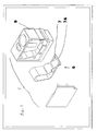
- Vue en éclaté d'un répartiteur en cours d'assemblage
- FIG 2 :
- vue en éclaté d'une borne à serrage élastique
- FIG 3 :
- Vue en coupe de la borne montée sur la base du répartiteur.
- FIG 4 :
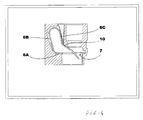
- Vue en coupe d'un exemple de borne.
- FIG 5 :
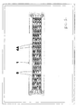
- un exemple en vue de dessus d'un répartiteur
- FIG 6 :
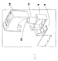
- Vue éclatée d'une variante de borne avec poussoir
- FIG 7 :
- la borne de la
figure 6 en cours de montage sur le support - FIG 8 :
- La borne de la
figure 6 montée. - En se reportant au dessin on voit un exemple de répartiteur 1 du type tétrapolaire, un neutre et trois phases.
- Ce répartiteur est destiné à distribuer du courant et comporte des bornes 5 de sortie sur lesquelles on engage un câble conducteur.
- Pour chaque pole il est prévu un conducteur principal 2, chacun étant logé dans des gouttières d'un corps isolant, ici une plaque 3 isolante commune aux quatre conducteurs.
- Sur cette plaque support 3 vient se fixer une grille 4 isolante délimitant des logements (emplacements) 4A pour des bornes 5 à serrage élastique qui sont fixées amovibles sur les conducteurs principaux par engagement de la borne dans le logement selon une direction perpendiculaire à la plaque support. Cette grille peut être solidaire de la plaque support.
- Pour le serrage élastique du câble, on utilise un ressort 6 en boucle dont une partie 6C applique le câble contre une pièce conductrice. Ici il est en outre prévu une fenêtre 7 de serrage destinée à recevoir l'extrémité dudit câble conducteur. Ce ressort est logé dans une chemise 9. On voit en
figure 2 , la chemise dont une paroi est démontée pour y introduire le ressort 6. - Lorsque le répartiteur est en l'état fonctionnel, on voit que cette fenêtre est également traversée par une pièce 8 conductrice établissant la liaison avec le conducteur principal.
- La pièce conductrice 8 est une languette portée par le conducteur principal. Elle est solidaire de ce conducteur.
- La borne est constituée par la chemise 9 qui loge uniquement le ressort de pression. Il s'agit d'une borne à une seule entrée (orifice 12).
- Avant montage de la borne, la languette est solidaire du conducteur principal.
- La languette est obtenue, par exemple, par découpe partielle d'une lame conductrice et pliage de la lame.
- Eventuellement pour la fabrication, afin d'obtenir une section de passage suffisante pour l'intensité du courant, on met en oeuvre une lame découpée et pliée qui peut être rapportée sur une lame plus épaisse par exemple par soudage, clinchage ou autre méthode qui permet d'assembler deux pièces et ne permettant pas de les séparer facilement.
- L'utilisateur dispose donc d'un support avec ses conducteurs principaux pourvus de leurs languettes en attente. Il peut acquérir le nombre de bornes souhaitées et les monter facilement où il le souhaite.
- Il suffit donc d'engager la chemise logeant le ressort dans la grille et sur la languette 8 pour positionner le ressort et établir le contact électrique avec le ressort. Des moyens de fixation présents sur la chemise verrouillent la dite chemise sur la grille.
- Des moyens d'ancrage rapide (clipsage) 20 permettent de fixer mécaniquement la chemise sur la grille isolante. En effet, il faut maintenir la chemise dans les logements de la grille.
- Le système ainsi construit est donc sans vis.
- Le ressort 6 qui forme une boucle comprend une base 6A présentant une fenêtre 7 de serrage, un dos 6B et une aile 6C de serrage s'engageant dans la fenêtre de serrage.
- Dans le mode de réalisation représenté, avant montage de la borne sur le support, l'aile 6C de serrage du ressort est légèrement écartée du bord extrême 7A transversal de la fenêtre de serrage afin d'engager facilement la languette 8 dans l'espace ainsi ménagé.
- Soit cet espace dans lequel s'engage la languette est obtenu par conformation du ressort à l'état repos soit le ressort est légèrement contraint lorsqu'il est placé dans la chemise. La chemise présente alors une face 10 de butée qui nécessite de pousser l'aile 6C de serrage vers le dos 6B du ressort lors de la mise en place dudit ressort dans la chemise. Le ressort ainsi contraint libère l'espace pour engager la fenêtre sur la languette. Cette deuxième solution est préférable.
- Dans une autre variante, le ressort est en appui sur le bord 7A extrême transversal de la fenêtre lorsqu'il est positionné dans la chemise et il faut un outil ou un autre moyen pour ouvrir un passage le temps d'introduire la languette.
- La languette pourra être biseautée pour faciliter son engagement dans la fenêtre de serrage.
- Lors de la mise en place du câble conducteur, le câble est pincé entre l'aile de serrage et la languette.
- Dans la solution représentée la chemise présente donc un orifice 12 pour introduire l'extrémité du câble dans la chemise et placer l'extrémité dénudée dans l'espace approprié. Un autre accès 13 permet à un outil de contraindre le ressort afin de retirer le câble ou le mettre en place.
- On notera que le ressort utilisé est conformé pour que le câble puisse être mis en place sans l'aide d'un outil. C'est l'extrémité du câble qui pousse le ressort en agissant sur l'aile de serrage.
- Dans une variante de réalisation, avant montage de la borne 5 sur le corps du répartiteur, l'aile de serrage du ressort est en appui sur le bord extrême 7A transversal de la fenêtre de serrage et nécessite d'être contrainte pour le passage de la languette au moyen, par exemple d'un outil.
- Au lieu et place d'un outil pour la mise en place de la languette, ou du câble ou son retrait, dans une variante de réalisation, il est prévu un bouton poussoir intégré.
- Le ressort 6 est logé dans sa chemise 9 qui vient coiffer une pièce 10 de guidage solidaire de la grille ou du support. Cette chemise comporte un poussoir 11 dont la face active 11A est en contact avec l'aile de serrage du ressort. La longueur du poussoir est telle que lorsque la face active est en contact avec le ressort (l'aile de serrage) non contraint, la face opposée 11B du poussoir est en saillie par rapport au sommet de la chemise de sorte que lorsqu'on met en place cette borne amovible sur le support en appuyant sur le dessus de la borne on appuie sur le poussoir et on contraint le ressort qui dégage la fenêtre de serrage pour permettre à la languette de se positionner dans l'espace dégagé de la fenêtre de serrage.
- Ce poussoir est traversé par un canal axial 12 permettant l'introduction d'un câble électrique dans la borne de serrage.
- Pour retirer le câble électrique lorsque celui-ci est verrouillé dans la fenêtre de serrage, on utilise le poussoir qui glisse le long du câble pour appuyer sur le ressort.
- Il n'est plus nécessaire de disposer d'un outil pour déverrouiller le câble.
- La solution présentée en
figure 6 à 8 comporte en plus un chapeau 13 qui coiffe la chemise. - Avec le répartiteur ainsi construit, on peut commercialiser indépendamment le support et les bornes. Le support existera avec différentes capacités ( 10 ou 20 ou 30 bornes par pole) et il achètera le nombre exact de bornes nécessaire à son installation. Si plus tard , il veut augmenter le nombre de points de distribution, il lui suffira d'acquérir le nombre de bornes correspondant.
- Le fait de ne pas intégrer dans la borne seule la présence d'une pièce de liaison en limite le cout. Il est en outre plus simple de monter ces bornes sur le support car le montage peut se faire sans outil. L'installateur peut optimiser son cout en prenant exactement le nombre de bornes nécessaires.
- Egalement, le problème du desserrage des vis n'existe plus.
- La formation de la languette, par exemple par découpe d'une plaque est peu onéreuse.
- On notera la non présence d'une butée limitant la compression du ressort.
Claims (10)
- Répartiteur à bornes à serrage élastique comprenant un corps isolant logeant au moins un conducteur principal et au moins une borne (5) apte à être fixée sur le corps du conducteur principal, ladite borne comprenant une chemise (9) logeant un ressort (6) de pression destiné à appliquer un câble sur une pièce (8) conductrice ce répartiteur étant caractérisé en ce que , d'une part, la borne (5) comporte un seul orifice d'entrée 1, elle est amovible du corps logeant le conducteur principal et lorsqu'elle n'est pas encore montée sur le corps du répartiteur, la chemise (9) loge uniquement le ressort (6) de pression et, d'autre part, la pièce (8) conductrice est une languette solidaire du conducteur principal.
- Répartiteur selon la revendication 1 caractérisé en ce que le ressort (6) qui forme une boucle comprend une base (6A) présentant une fenêtre (7 )de serrage, un dos (6B) et une aile (6C) de serrage s'engageant dans la fenêtre de serrage.
- Répartiteur selon la revendication 2 caractérisé en ce qu'avant montage de la borne (5) sur le support, l'aile de serrage du ressort est légèrement écartée du bord extrême (7A) transversal de la fenêtre de serrage afin d'engager facilement la languette (8) dans l'espace ainsi ménagé.
- Répartiteur selon la revendication 3 caractérisé en ce que l'espace dans lequel s'engage la languette est obtenu par conformation du ressort à l'état repos.
- Répartiteur selon la revendication 3 caractérisé en ce qu'une butée présentée par la chemise contraint le ressort pour libérer un espace pour le passage de la languette.
- Répartiteur selon la revendication 2 caractérisé en ce qu'avant montage de la borne (5) sur le corps du répartiteur, l'aile de serrage du ressort est en appui sur le bord extrême (7A) transversal de la fenêtre de serrage et nécessite d'être contrainte pour le passage de la languette.
- Répartiteur selon la revendication 3 à 6 caractérisé en ce qu'un poussoir intégré dans la borne amovible permet de contraindre le ressort.
- Répartiteur selon la revendication 7 caractérisé en ce que le poussoir est traversé par un canal axial permettant l'introduction d'un câble électrique dans la borne à serrage élastique.
- Répartiteur selon la revendication 1 caractérisé en ce que la languette 8 est présentée par une lame découpée et pliée qui est rapportée sur une lame plus épaisse
- Répartiteur selon l'une quelconque des revendications 1 à 9 caractérisé en ce que le corps logeant le/les conducteurs principaux à la forme d'une grille délimitant des logements, chaque logement pouvant accueillir une borne.
Applications Claiming Priority (1)
| Application Number | Priority Date | Filing Date | Title |
|---|---|---|---|
| FR0904543A FR2950485B1 (fr) | 2009-09-23 | 2009-09-23 | Repartiteur a bornes elastiques |
Publications (2)
| Publication Number | Publication Date |
|---|---|
| EP2306590A1 true EP2306590A1 (fr) | 2011-04-06 |
| EP2306590B1 EP2306590B1 (fr) | 2015-03-25 |
Family
ID=42105851
Family Applications (1)
| Application Number | Title | Priority Date | Filing Date |
|---|---|---|---|
| EP10350007.0A Not-in-force EP2306590B1 (fr) | 2009-09-23 | 2010-09-23 | Répartiteur à bornes élastiques |
Country Status (2)
| Country | Link |
|---|---|
| EP (1) | EP2306590B1 (fr) |
| FR (1) | FR2950485B1 (fr) |
Cited By (4)
| Publication number | Priority date | Publication date | Assignee | Title |
|---|---|---|---|---|
| FR2981213A1 (fr) * | 2011-10-05 | 2013-04-12 | Legrand France | Dispositif de raccordement electrique. |
| GB2561029A (en) * | 2017-03-26 | 2018-10-03 | Clickfit Electrical Ltd | Multi wire cable connector assembly |
| DE102018127715A1 (de) * | 2018-11-07 | 2020-05-07 | Phoenix Contact Gmbh & Co. Kg | Stromschienensystem |
| CN112582850A (zh) * | 2019-09-27 | 2021-03-30 | 菲尼克斯电气公司 | 汇流排模块和相应的接线模块 |
Citations (4)
| Publication number | Priority date | Publication date | Assignee | Title |
|---|---|---|---|---|
| FR2792778A1 (fr) * | 1999-04-22 | 2000-10-27 | Schneider Electric Sa | Borne elastique d'appareil electrique |
| DE20120811U1 (de) * | 2001-12-21 | 2003-04-30 | Weidmüller Interface GmbH & Co., 32760 Detmold | Sammelschienen-Anschlußklemme |
| DE102005056325A1 (de) | 2005-11-25 | 2007-06-06 | Phoenix Contact Gmbh & Co. Kg | Printklemme für Leiterplattenanschluß |
| DE102008017738A1 (de) * | 2007-04-21 | 2008-10-30 | Abb Ag | Installationsschaltgerät mit einer Federzugklemmenanordnung |
-
2009
- 2009-09-23 FR FR0904543A patent/FR2950485B1/fr not_active Expired - Fee Related
-
2010
- 2010-09-23 EP EP10350007.0A patent/EP2306590B1/fr not_active Not-in-force
Patent Citations (5)
| Publication number | Priority date | Publication date | Assignee | Title |
|---|---|---|---|---|
| FR2792778A1 (fr) * | 1999-04-22 | 2000-10-27 | Schneider Electric Sa | Borne elastique d'appareil electrique |
| EP1052729A1 (fr) | 1999-04-22 | 2000-11-15 | Schneider Electric Industries SA | Borne élastique d'appareil électrique |
| DE20120811U1 (de) * | 2001-12-21 | 2003-04-30 | Weidmüller Interface GmbH & Co., 32760 Detmold | Sammelschienen-Anschlußklemme |
| DE102005056325A1 (de) | 2005-11-25 | 2007-06-06 | Phoenix Contact Gmbh & Co. Kg | Printklemme für Leiterplattenanschluß |
| DE102008017738A1 (de) * | 2007-04-21 | 2008-10-30 | Abb Ag | Installationsschaltgerät mit einer Federzugklemmenanordnung |
Cited By (8)
| Publication number | Priority date | Publication date | Assignee | Title |
|---|---|---|---|---|
| FR2981213A1 (fr) * | 2011-10-05 | 2013-04-12 | Legrand France | Dispositif de raccordement electrique. |
| GB2561029A (en) * | 2017-03-26 | 2018-10-03 | Clickfit Electrical Ltd | Multi wire cable connector assembly |
| DE102018127715A1 (de) * | 2018-11-07 | 2020-05-07 | Phoenix Contact Gmbh & Co. Kg | Stromschienensystem |
| EP3651272A1 (fr) * | 2018-11-07 | 2020-05-13 | Phoenix Contact GmbH & Co. KG | Système de rail conducteur |
| CN111162391A (zh) * | 2018-11-07 | 2020-05-15 | 菲尼克斯电气公司 | 导电轨系统 |
| CN111162391B (zh) * | 2018-11-07 | 2022-05-06 | 菲尼克斯电气公司 | 导电轨系统 |
| CN112582850A (zh) * | 2019-09-27 | 2021-03-30 | 菲尼克斯电气公司 | 汇流排模块和相应的接线模块 |
| CN112582850B (zh) * | 2019-09-27 | 2023-02-21 | 菲尼克斯电气公司 | 汇流排模块和相应的接线模块 |
Also Published As
| Publication number | Publication date |
|---|---|
| FR2950485B1 (fr) | 2012-11-16 |
| FR2950485A1 (fr) | 2011-03-25 |
| EP2306590B1 (fr) | 2015-03-25 |
Similar Documents
| Publication | Publication Date | Title |
|---|---|---|
| EP3807956B1 (fr) | Clip metallique de connexion electrique d'un fil conducteur a un element metallique | |
| CA2987825A1 (fr) | Clip metallique de connexion electrique d'un fil conducteur a un element metallique | |
| EP2306590B1 (fr) | Répartiteur à bornes élastiques | |
| EP3605749A1 (fr) | Support d'appareillage électrique et appareillage électrique associé | |
| CA1208731A (fr) | Dispositif de connexion pour conducteur electrique | |
| EP1052729A1 (fr) | Borne élastique d'appareil électrique | |
| EP1411590B1 (fr) | Borne de connexion élastique | |
| CH680245A5 (fr) | ||
| FR2620578A1 (fr) | Dispositif de raccordement electrique pour borne d'appareil electrique, disjoncteur ainsi equipe, et ensemble de constituants s'y rapportant | |
| FR2740911A1 (fr) | Appareil electrique a bornes de raccordement protegees par un diaphragme a fixation par des ailes | |
| EP1134768B1 (fr) | Ensemble de départ-moteur | |
| EP3089295A1 (fr) | Dispositif d'interconnexion électrique configuré pour établir une liaison équipotentielle entre un tronçon de chemin de câbles et un tronçon de câble électrique | |
| EP3598582B1 (fr) | Dispositif de connexion électrique | |
| WO2018059694A1 (fr) | Système de liaison électrique avec une lame conductrice | |
| CA2155402C (fr) | Connexion auto-denudante a action rapide | |
| EP0961353B1 (fr) | Mécanisme de connexion, en particulier pour sortie de câble ou dérivation | |
| EP3032562A1 (fr) | Dispositif de raccordement électrique comportant une sortie auxiliaire et appareil de commutation comportant un tel dispositif | |
| EP1610416B1 (fr) | Appareil électrique adapté à coopérer avec un peigne de répartition horizontale | |
| EP0908972B1 (fr) | Serre-câble et appareil électrique équipé d'un tel serre-câble | |
| EP1156551A1 (fr) | Appareil électrique à bornes dotées de cages élastiques | |
| EP0706252B1 (fr) | Support d'appareillage à rapporter sur une boíte d'encastrement, et bloc de fixation propre à l'équipement d'un tel support d'appareillage | |
| FR2860095A1 (fr) | Barre de raccordement electrique et dispositif de connexion adapte | |
| FR2936367A1 (fr) | Connecteur electrique | |
| FR3028356A1 (fr) | Borne de connexion electrique a vis imperdable | |
| FR2839819A1 (fr) | Boitier a brides pour cloisons creuses |
Legal Events
| Date | Code | Title | Description |
|---|---|---|---|
| PUAI | Public reference made under article 153(3) epc to a published international application that has entered the european phase |
Free format text: ORIGINAL CODE: 0009012 |
|
| AK | Designated contracting states |
Kind code of ref document: A1 Designated state(s): AL AT BE BG CH CY CZ DE DK EE ES FI FR GB GR HR HU IE IS IT LI LT LU LV MC MK MT NL NO PL PT RO SE SI SK SM TR |
|
| AX | Request for extension of the european patent |
Extension state: BA ME RS |
|
| 17P | Request for examination filed |
Effective date: 20110920 |
|
| GRAP | Despatch of communication of intention to grant a patent |
Free format text: ORIGINAL CODE: EPIDOSNIGR1 |
|
| RIC1 | Information provided on ipc code assigned before grant |
Ipc: H01R 25/16 20060101ALI20141015BHEP Ipc: H01R 4/48 20060101AFI20141015BHEP |
|
| INTG | Intention to grant announced |
Effective date: 20141113 |
|
| GRAS | Grant fee paid |
Free format text: ORIGINAL CODE: EPIDOSNIGR3 |
|
| GRAA | (expected) grant |
Free format text: ORIGINAL CODE: 0009210 |
|
| AK | Designated contracting states |
Kind code of ref document: B1 Designated state(s): AL AT BE BG CH CY CZ DE DK EE ES FI FR GB GR HR HU IE IS IT LI LT LU LV MC MK MT NL NO PL PT RO SE SI SK SM TR |
|
| REG | Reference to a national code |
Ref country code: GB Ref legal event code: FG4D Free format text: NOT ENGLISH |
|
| REG | Reference to a national code |
Ref country code: CH Ref legal event code: EP |
|
| REG | Reference to a national code |
Ref country code: IE Ref legal event code: FG4D Free format text: LANGUAGE OF EP DOCUMENT: FRENCH |
|
| REG | Reference to a national code |
Ref country code: DE Ref legal event code: R096 Ref document number: 602010023358 Country of ref document: DE Effective date: 20150507 |
|
| REG | Reference to a national code |
Ref country code: AT Ref legal event code: REF Ref document number: 718367 Country of ref document: AT Kind code of ref document: T Effective date: 20150515 |
|
| PG25 | Lapsed in a contracting state [announced via postgrant information from national office to epo] |
Ref country code: FI Free format text: LAPSE BECAUSE OF FAILURE TO SUBMIT A TRANSLATION OF THE DESCRIPTION OR TO PAY THE FEE WITHIN THE PRESCRIBED TIME-LIMIT Effective date: 20150325 Ref country code: SE Free format text: LAPSE BECAUSE OF FAILURE TO SUBMIT A TRANSLATION OF THE DESCRIPTION OR TO PAY THE FEE WITHIN THE PRESCRIBED TIME-LIMIT Effective date: 20150325 Ref country code: NO Free format text: LAPSE BECAUSE OF FAILURE TO SUBMIT A TRANSLATION OF THE DESCRIPTION OR TO PAY THE FEE WITHIN THE PRESCRIBED TIME-LIMIT Effective date: 20150625 Ref country code: HR Free format text: LAPSE BECAUSE OF FAILURE TO SUBMIT A TRANSLATION OF THE DESCRIPTION OR TO PAY THE FEE WITHIN THE PRESCRIBED TIME-LIMIT Effective date: 20150325 Ref country code: LT Free format text: LAPSE BECAUSE OF FAILURE TO SUBMIT A TRANSLATION OF THE DESCRIPTION OR TO PAY THE FEE WITHIN THE PRESCRIBED TIME-LIMIT Effective date: 20150325 |
|
| REG | Reference to a national code |
Ref country code: AT Ref legal event code: MK05 Ref document number: 718367 Country of ref document: AT Kind code of ref document: T Effective date: 20150325 |
|
| REG | Reference to a national code |
Ref country code: LT Ref legal event code: MG4D |
|
| PG25 | Lapsed in a contracting state [announced via postgrant information from national office to epo] |
Ref country code: LV Free format text: LAPSE BECAUSE OF FAILURE TO SUBMIT A TRANSLATION OF THE DESCRIPTION OR TO PAY THE FEE WITHIN THE PRESCRIBED TIME-LIMIT Effective date: 20150325 Ref country code: GR Free format text: LAPSE BECAUSE OF FAILURE TO SUBMIT A TRANSLATION OF THE DESCRIPTION OR TO PAY THE FEE WITHIN THE PRESCRIBED TIME-LIMIT Effective date: 20150626 |
|
| REG | Reference to a national code |
Ref country code: FR Ref legal event code: PLFP Year of fee payment: 6 |
|
| PG25 | Lapsed in a contracting state [announced via postgrant information from national office to epo] |
Ref country code: NL Free format text: LAPSE BECAUSE OF FAILURE TO SUBMIT A TRANSLATION OF THE DESCRIPTION OR TO PAY THE FEE WITHIN THE PRESCRIBED TIME-LIMIT Effective date: 20150325 |
|
| PG25 | Lapsed in a contracting state [announced via postgrant information from national office to epo] |
Ref country code: RO Free format text: LAPSE BECAUSE OF FAILURE TO SUBMIT A TRANSLATION OF THE DESCRIPTION OR TO PAY THE FEE WITHIN THE PRESCRIBED TIME-LIMIT Effective date: 20150325 Ref country code: SK Free format text: LAPSE BECAUSE OF FAILURE TO SUBMIT A TRANSLATION OF THE DESCRIPTION OR TO PAY THE FEE WITHIN THE PRESCRIBED TIME-LIMIT Effective date: 20150325 Ref country code: PT Free format text: LAPSE BECAUSE OF FAILURE TO SUBMIT A TRANSLATION OF THE DESCRIPTION OR TO PAY THE FEE WITHIN THE PRESCRIBED TIME-LIMIT Effective date: 20150727 Ref country code: ES Free format text: LAPSE BECAUSE OF FAILURE TO SUBMIT A TRANSLATION OF THE DESCRIPTION OR TO PAY THE FEE WITHIN THE PRESCRIBED TIME-LIMIT Effective date: 20150325 Ref country code: EE Free format text: LAPSE BECAUSE OF FAILURE TO SUBMIT A TRANSLATION OF THE DESCRIPTION OR TO PAY THE FEE WITHIN THE PRESCRIBED TIME-LIMIT Effective date: 20150325 Ref country code: CZ Free format text: LAPSE BECAUSE OF FAILURE TO SUBMIT A TRANSLATION OF THE DESCRIPTION OR TO PAY THE FEE WITHIN THE PRESCRIBED TIME-LIMIT Effective date: 20150325 |
|
| PG25 | Lapsed in a contracting state [announced via postgrant information from national office to epo] |
Ref country code: IS Free format text: LAPSE BECAUSE OF FAILURE TO SUBMIT A TRANSLATION OF THE DESCRIPTION OR TO PAY THE FEE WITHIN THE PRESCRIBED TIME-LIMIT Effective date: 20150725 Ref country code: PL Free format text: LAPSE BECAUSE OF FAILURE TO SUBMIT A TRANSLATION OF THE DESCRIPTION OR TO PAY THE FEE WITHIN THE PRESCRIBED TIME-LIMIT Effective date: 20150325 Ref country code: AT Free format text: LAPSE BECAUSE OF FAILURE TO SUBMIT A TRANSLATION OF THE DESCRIPTION OR TO PAY THE FEE WITHIN THE PRESCRIBED TIME-LIMIT Effective date: 20150325 |
|
| REG | Reference to a national code |
Ref country code: DE Ref legal event code: R097 Ref document number: 602010023358 Country of ref document: DE |
|
| PG25 | Lapsed in a contracting state [announced via postgrant information from national office to epo] |
Ref country code: DK Free format text: LAPSE BECAUSE OF FAILURE TO SUBMIT A TRANSLATION OF THE DESCRIPTION OR TO PAY THE FEE WITHIN THE PRESCRIBED TIME-LIMIT Effective date: 20150325 |
|
| PLBE | No opposition filed within time limit |
Free format text: ORIGINAL CODE: 0009261 |
|
| STAA | Information on the status of an ep patent application or granted ep patent |
Free format text: STATUS: NO OPPOSITION FILED WITHIN TIME LIMIT |
|
| 26N | No opposition filed |
Effective date: 20160105 |
|
| PG25 | Lapsed in a contracting state [announced via postgrant information from national office to epo] |
Ref country code: LU Free format text: LAPSE BECAUSE OF FAILURE TO SUBMIT A TRANSLATION OF THE DESCRIPTION OR TO PAY THE FEE WITHIN THE PRESCRIBED TIME-LIMIT Effective date: 20150923 Ref country code: IT Free format text: LAPSE BECAUSE OF FAILURE TO SUBMIT A TRANSLATION OF THE DESCRIPTION OR TO PAY THE FEE WITHIN THE PRESCRIBED TIME-LIMIT Effective date: 20150325 Ref country code: MC Free format text: LAPSE BECAUSE OF FAILURE TO SUBMIT A TRANSLATION OF THE DESCRIPTION OR TO PAY THE FEE WITHIN THE PRESCRIBED TIME-LIMIT Effective date: 20150325 |
|
| REG | Reference to a national code |
Ref country code: CH Ref legal event code: PL |
|
| PG25 | Lapsed in a contracting state [announced via postgrant information from national office to epo] |
Ref country code: SI Free format text: LAPSE BECAUSE OF FAILURE TO SUBMIT A TRANSLATION OF THE DESCRIPTION OR TO PAY THE FEE WITHIN THE PRESCRIBED TIME-LIMIT Effective date: 20150325 |
|
| REG | Reference to a national code |
Ref country code: IE Ref legal event code: MM4A |
|
| PG25 | Lapsed in a contracting state [announced via postgrant information from national office to epo] |
Ref country code: LI Free format text: LAPSE BECAUSE OF NON-PAYMENT OF DUE FEES Effective date: 20150930 Ref country code: CH Free format text: LAPSE BECAUSE OF NON-PAYMENT OF DUE FEES Effective date: 20150930 Ref country code: IE Free format text: LAPSE BECAUSE OF NON-PAYMENT OF DUE FEES Effective date: 20150923 |
|
| REG | Reference to a national code |
Ref country code: FR Ref legal event code: PLFP Year of fee payment: 7 |
|
| PG25 | Lapsed in a contracting state [announced via postgrant information from national office to epo] |
Ref country code: MT Free format text: LAPSE BECAUSE OF FAILURE TO SUBMIT A TRANSLATION OF THE DESCRIPTION OR TO PAY THE FEE WITHIN THE PRESCRIBED TIME-LIMIT Effective date: 20150325 |
|
| PG25 | Lapsed in a contracting state [announced via postgrant information from national office to epo] |
Ref country code: SM Free format text: LAPSE BECAUSE OF FAILURE TO SUBMIT A TRANSLATION OF THE DESCRIPTION OR TO PAY THE FEE WITHIN THE PRESCRIBED TIME-LIMIT Effective date: 20150325 Ref country code: BG Free format text: LAPSE BECAUSE OF FAILURE TO SUBMIT A TRANSLATION OF THE DESCRIPTION OR TO PAY THE FEE WITHIN THE PRESCRIBED TIME-LIMIT Effective date: 20150325 Ref country code: HU Free format text: LAPSE BECAUSE OF FAILURE TO SUBMIT A TRANSLATION OF THE DESCRIPTION OR TO PAY THE FEE WITHIN THE PRESCRIBED TIME-LIMIT; INVALID AB INITIO Effective date: 20100923 |
|
| PG25 | Lapsed in a contracting state [announced via postgrant information from national office to epo] |
Ref country code: CY Free format text: LAPSE BECAUSE OF FAILURE TO SUBMIT A TRANSLATION OF THE DESCRIPTION OR TO PAY THE FEE WITHIN THE PRESCRIBED TIME-LIMIT Effective date: 20150325 |
|
| PG25 | Lapsed in a contracting state [announced via postgrant information from national office to epo] |
Ref country code: BE Free format text: LAPSE BECAUSE OF NON-PAYMENT OF DUE FEES Effective date: 20150930 |
|
| PG25 | Lapsed in a contracting state [announced via postgrant information from national office to epo] |
Ref country code: TR Free format text: LAPSE BECAUSE OF FAILURE TO SUBMIT A TRANSLATION OF THE DESCRIPTION OR TO PAY THE FEE WITHIN THE PRESCRIBED TIME-LIMIT Effective date: 20150325 |
|
| REG | Reference to a national code |
Ref country code: FR Ref legal event code: PLFP Year of fee payment: 8 |
|
| PG25 | Lapsed in a contracting state [announced via postgrant information from national office to epo] |
Ref country code: MK Free format text: LAPSE BECAUSE OF FAILURE TO SUBMIT A TRANSLATION OF THE DESCRIPTION OR TO PAY THE FEE WITHIN THE PRESCRIBED TIME-LIMIT Effective date: 20150325 |
|
| REG | Reference to a national code |
Ref country code: FR Ref legal event code: PLFP Year of fee payment: 9 |
|
| PG25 | Lapsed in a contracting state [announced via postgrant information from national office to epo] |
Ref country code: AL Free format text: LAPSE BECAUSE OF FAILURE TO SUBMIT A TRANSLATION OF THE DESCRIPTION OR TO PAY THE FEE WITHIN THE PRESCRIBED TIME-LIMIT Effective date: 20150325 |
|
| PGFP | Annual fee paid to national office [announced via postgrant information from national office to epo] |
Ref country code: DE Payment date: 20200929 Year of fee payment: 11 Ref country code: GB Payment date: 20200928 Year of fee payment: 11 Ref country code: FR Payment date: 20200921 Year of fee payment: 11 |
|
| REG | Reference to a national code |
Ref country code: DE Ref legal event code: R119 Ref document number: 602010023358 Country of ref document: DE |
|
| GBPC | Gb: european patent ceased through non-payment of renewal fee |
Effective date: 20210923 |
|
| PG25 | Lapsed in a contracting state [announced via postgrant information from national office to epo] |
Ref country code: GB Free format text: LAPSE BECAUSE OF NON-PAYMENT OF DUE FEES Effective date: 20210923 Ref country code: FR Free format text: LAPSE BECAUSE OF NON-PAYMENT OF DUE FEES Effective date: 20210930 Ref country code: DE Free format text: LAPSE BECAUSE OF NON-PAYMENT OF DUE FEES Effective date: 20220401 |