EP2306368A2 - Image processing device having a plurality of control units - Google Patents
Image processing device having a plurality of control units Download PDFInfo
- Publication number
- EP2306368A2 EP2306368A2 EP10251023A EP10251023A EP2306368A2 EP 2306368 A2 EP2306368 A2 EP 2306368A2 EP 10251023 A EP10251023 A EP 10251023A EP 10251023 A EP10251023 A EP 10251023A EP 2306368 A2 EP2306368 A2 EP 2306368A2
- Authority
- EP
- European Patent Office
- Prior art keywords
- mode
- unit
- control unit
- control
- function
- Prior art date
- Legal status (The legal status is an assumption and is not a legal conclusion. Google has not performed a legal analysis and makes no representation as to the accuracy of the status listed.)
- Granted
Links
Images



Classifications
-
- G—PHYSICS
- G06—COMPUTING OR CALCULATING; COUNTING
- G06K—GRAPHICAL DATA READING; PRESENTATION OF DATA; RECORD CARRIERS; HANDLING RECORD CARRIERS
- G06K15/00—Arrangements for producing a permanent visual presentation of the output data, e.g. computer output printers
-
- G—PHYSICS
- G03—PHOTOGRAPHY; CINEMATOGRAPHY; ANALOGOUS TECHNIQUES USING WAVES OTHER THAN OPTICAL WAVES; ELECTROGRAPHY; HOLOGRAPHY
- G03G—ELECTROGRAPHY; ELECTROPHOTOGRAPHY; MAGNETOGRAPHY
- G03G15/00—Apparatus for electrographic processes using a charge pattern
- G03G15/50—Machine control of apparatus for electrographic processes using a charge pattern, e.g. regulating differents parts of the machine, multimode copiers, microprocessor control
- G03G15/5004—Power supply control, e.g. power-saving mode, automatic power turn-off
-
- G—PHYSICS
- G06—COMPUTING OR CALCULATING; COUNTING
- G06F—ELECTRIC DIGITAL DATA PROCESSING
- G06F1/00—Details not covered by groups G06F3/00 - G06F13/00 and G06F21/00
- G06F1/26—Power supply means, e.g. regulation thereof
- G06F1/32—Means for saving power
- G06F1/3203—Power management, i.e. event-based initiation of a power-saving mode
-
- G—PHYSICS
- G06—COMPUTING OR CALCULATING; COUNTING
- G06F—ELECTRIC DIGITAL DATA PROCESSING
- G06F1/00—Details not covered by groups G06F3/00 - G06F13/00 and G06F21/00
- G06F1/26—Power supply means, e.g. regulation thereof
- G06F1/32—Means for saving power
- G06F1/3203—Power management, i.e. event-based initiation of a power-saving mode
- G06F1/3206—Monitoring of events, devices or parameters that trigger a change in power modality
- G06F1/3215—Monitoring of peripheral devices
-
- G—PHYSICS
- G06—COMPUTING OR CALCULATING; COUNTING
- G06F—ELECTRIC DIGITAL DATA PROCESSING
- G06F1/00—Details not covered by groups G06F3/00 - G06F13/00 and G06F21/00
- G06F1/26—Power supply means, e.g. regulation thereof
- G06F1/32—Means for saving power
- G06F1/3203—Power management, i.e. event-based initiation of a power-saving mode
- G06F1/3234—Power saving characterised by the action undertaken
- G06F1/325—Power saving in peripheral device
- G06F1/3284—Power saving in printer
-
- G—PHYSICS
- G06—COMPUTING OR CALCULATING; COUNTING
- G06K—GRAPHICAL DATA READING; PRESENTATION OF DATA; RECORD CARRIERS; HANDLING RECORD CARRIERS
- G06K15/00—Arrangements for producing a permanent visual presentation of the output data, e.g. computer output printers
- G06K15/02—Arrangements for producing a permanent visual presentation of the output data, e.g. computer output printers using printers
- G06K15/18—Conditioning data for presenting it to the physical printing elements
-
- G—PHYSICS
- G06—COMPUTING OR CALCULATING; COUNTING
- G06K—GRAPHICAL DATA READING; PRESENTATION OF DATA; RECORD CARRIERS; HANDLING RECORD CARRIERS
- G06K15/00—Arrangements for producing a permanent visual presentation of the output data, e.g. computer output printers
- G06K15/40—Details not directly involved in printing, e.g. machine management, management of the arrangement as a whole or of its constitutive parts
- G06K15/4055—Managing power consumption, e.g. standby mode
- G06K15/406—Wake-up procedures
-
- G—PHYSICS
- G03—PHOTOGRAPHY; CINEMATOGRAPHY; ANALOGOUS TECHNIQUES USING WAVES OTHER THAN OPTICAL WAVES; ELECTROGRAPHY; HOLOGRAPHY
- G03G—ELECTROGRAPHY; ELECTROPHOTOGRAPHY; MAGNETOGRAPHY
- G03G2215/00—Apparatus for electrophotographic processes
- G03G2215/06—Developing structures, details
- G03G2215/066—Toner cartridge or other attachable and detachable container for supplying developer material to replace the used material
- G03G2215/0695—Toner cartridge or other attachable and detachable container for supplying developer material to replace the used material using identification means or means for storing process or use parameters
- G03G2215/0697—Toner cartridge or other attachable and detachable container for supplying developer material to replace the used material using identification means or means for storing process or use parameters being an electronically readable memory
-
- Y—GENERAL TAGGING OF NEW TECHNOLOGICAL DEVELOPMENTS; GENERAL TAGGING OF CROSS-SECTIONAL TECHNOLOGIES SPANNING OVER SEVERAL SECTIONS OF THE IPC; TECHNICAL SUBJECTS COVERED BY FORMER USPC CROSS-REFERENCE ART COLLECTIONS [XRACs] AND DIGESTS
- Y02—TECHNOLOGIES OR APPLICATIONS FOR MITIGATION OR ADAPTATION AGAINST CLIMATE CHANGE
- Y02D—CLIMATE CHANGE MITIGATION TECHNOLOGIES IN INFORMATION AND COMMUNICATION TECHNOLOGIES [ICT], I.E. INFORMATION AND COMMUNICATION TECHNOLOGIES AIMING AT THE REDUCTION OF THEIR OWN ENERGY USE
- Y02D10/00—Energy efficient computing, e.g. low power processors, power management or thermal management
-
- Y—GENERAL TAGGING OF NEW TECHNOLOGICAL DEVELOPMENTS; GENERAL TAGGING OF CROSS-SECTIONAL TECHNOLOGIES SPANNING OVER SEVERAL SECTIONS OF THE IPC; TECHNICAL SUBJECTS COVERED BY FORMER USPC CROSS-REFERENCE ART COLLECTIONS [XRACs] AND DIGESTS
- Y02—TECHNOLOGIES OR APPLICATIONS FOR MITIGATION OR ADAPTATION AGAINST CLIMATE CHANGE
- Y02D—CLIMATE CHANGE MITIGATION TECHNOLOGIES IN INFORMATION AND COMMUNICATION TECHNOLOGIES [ICT], I.E. INFORMATION AND COMMUNICATION TECHNOLOGIES AIMING AT THE REDUCTION OF THEIR OWN ENERGY USE
- Y02D30/00—Reducing energy consumption in communication networks
- Y02D30/50—Reducing energy consumption in communication networks in wire-line communication networks, e.g. low power modes or reduced link rate
Definitions
- the present invention relates to an image processing device and a storage medium storing a control program for controlling the image processing device.
- Japanese Patent-Application Publication No. H8-101609 has proposed an image processing device including a main control unit and a sub-control unit.
- the main control unit controls each of various units, such as a printer unit, and the sub-control unit controls an interface for communicating with external devices.
- the main control unit is placed in a sleep state, and only the sub-control unit is in a running state. This configuration reduces power consumption in the power-saving mode.
- an object of the invention to provide an image processing device capable of avoiding limiting functions executable under the control of one or more of a plurality of control units. It is also an object of the invention to provide a storage medium storing a program for controlling the image processing device.
- the invention provides an image processing device including an operating unit, a plurality of control units, and a selecting unit.
- Each of the plurality of control units includes a processing unit and is configured to control the operating unit in order to execute a target function on image data.
- the plurality of control units includes at least a first control unit and a second control unit.
- the selecting unit selects one of a first mode and a second mode. When the first mode is selected, the plurality of control units control the operating unit to execute the target function in cooperation with each other. When the second mode is selected, at least the second control unit controls the operating unit to execute the target function without cooperating with the first control unit.
- the present invention provides a storage medium storing a set of program instructions executable on an image processing device and usable for controlling the image processing device.
- the image processing device includes an operating unit and a plurality of control units.
- the plurality of control units include at least a first control unit and a second control unit. Instructions include selecting one of a first mode and a second mode, controlling the plurality of control units to control the operating unit so as to execute a function on image data in cooperation with each other when the first mode is selected, and controlling at least the second control unit to control the operating unit so as to execute the function without cooperating with the first control unit when the second mode is selected.
- Fig. 1 is a block diagram showing electrical configuration of an image processing system according to a first embodiment of the invention
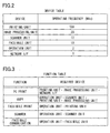
- Fig. 2 is a view showing a device table according to the first embodiment of the invention.
- Fig. 3 is a view showing a function table according to the first embodiment of the invention.
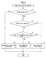
- Fig. 4 is a flowchart representing a function execution process according to the first embodiment of the invention.
- Fig. 5 is a flowchart representing a function execution process according to a second embodiment of the invention.
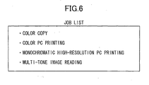
- Fig. 6 is a view showing a job list according to the second embodiment of the invention.
- Fig. 7 is a flowchart representing a function execution process according to a third embodiment of the invention.
- an image processing system 1 includes a terminal device 10 and a printer 30 (image processing device).
- the terminal device 10 may be a personal computer, for example.
- the terminal device 10 includes a CPU 11, a ROM 12, a RAM 13, a hard disk drive (HDD) 14, an operation unit 15, a display unit 16, and a network interface (I/F) 17.
- the operation unit 15 includes a keyboard and a pointing device
- the display unit 16 includes a liquid crystal display panel.
- the network I/F 17 is connected to a communication circuit 20.
- the HDD 14 stores various programs including an operation system (OS), an application software for generating image data to be printed, and a printer driver for controlling the printer 30.
- the CPU 11 performs overall control of the terminal device 10 based on a program read from the ROM 12 while storing processed results in the RAM 13.
- OS operation system
- the CPU 11 performs overall control of the terminal device 10 based on a program read from the ROM 12 while storing processed results in the RAM 13.
- the printer 30 is a multifunction device capable of executing a plurality of functions including a PC print function, a copy function, a scanner function, a facsimile communication function, and a facsimile print function.
- the printer 30 includes a first control unit 31, a second control unit 32, and a HDD 34.
- the first control unit 31 includes a first CPU 31A, a ROM 31B, and a RAM 31C.
- the second control unit 32 includes a second CPU 32A, a ROM 32B, and a RAM 32C
- Each of the ROM 31B and the ROM 32B stores various programs for controlling the printer 30.
- Each of the first CPU 31A and the second CPU 32A performs overall control of the printer 30 based on a program read from the respective ROM 31B, 32B while storing processed results into the respective RAM 31C, 32C.
- the first and second control units 31 and 32 have substantially the same performance level. More specifically, both the first and second control units 31 and 32 have substantially the same operating frequency (100 MHz, in this embodiment), and the RAMs 31C and 32C have substantially the same memory capacity.
- the printer 30 further includes various devices (operating units) including a network I/F 21, an operation unit 35, a scanner unit 36, a facsimile unit 37, an image processing unit 38, and a printing unit 39.
- various devices including a network I/F 21, an operation unit 35, a scanner unit 36, a facsimile unit 37, an image processing unit 38, and a printing unit 39.
- the network I/F 21 is connected to the terminal device 10 and the like through the communication circuit 20, enabling data communication therebetween.
- the operation unit 35 includes various buttons through which a user inputs various commands including an execution command for each function.
- the operation unit 35 also includes a display unit (liquid crystal display panel, for example) and a lamp, and is capable of displaying various setting screens and operation status.
- the scanner unit 36 generates scanned data by scanning an original (not shown).
- the facsimile unit 37 transmits facsimile data to or receives facsimile data from a remote facsimile device (not shown).
- the image processing unit 38 image-processes various image data. For example, the image processing unit 38 converts the image data into printable data.
- the image data may be scanned data generated by the scanner unit 36, print data received at the network I/F 21, or the like.
- the printing unit 39 forms an image on a recording sheet (paper sheet, OHP sheet, or the like) based on the image data in an electrophotographic method, for example.
- the printing unit 39 includes a sheet-conveying mechanism 40 and a fixing unit 41.
- the sheet-conveying mechanism 40 picks up recording sheets one at a time from a sheet tray (not shown) and conveys the same to a printing section (not shown), in accordance with a print start command from the first or second control unit 31, 32.
- Each of the first and second control units 31 and 32 is capable of controlling the sheet-conveying mechanism 40 to change a sheet conveying speed as needed.
- the fixing unit 41 thermally fixes toner images transferred onto the recording sheet.
- Each of the first and second control units 31 and 32 is capable of controlling the amount of heat (temperature) generated at the fixing unit 41 by controlling the amount of electric supply to the fixing unit 41.
- Fig. 2 shows a device table, which is stored in the HDD 34, for example.
- the device table shows operating frequencies (clock numbers) required to operate each of the devices (the printing unit 39, the image processing unit 38, the scanner unit 36, the facsimile unit 37, the operation unit 35, and the network I/F 21).
- the operating frequencies of the first and second control units 31 and 32 are both 100 MHz.
- each of the first and second control units 31 and 32 is capable of operating any of the devices by itself.
- Fig. 3 shows a function table, which is stored in the HDD 34, for example.
- the function table identifies devices required for each function.
- the network I/F 21 receives print data from the terminal device 10, and the image processing unit 38 image-processes the print data (expands the print data into bitmap data, for example), and the printing unit 39 forms a print-object image on a recording medium.
- the network I/F 21, the image processing unit 38, and the printing unit 39 are required for the PC print function.
- the operation unit 35 accepts a copy request from a user, and the scanner unit 36 generates scanned data by scanning an original, and the image processing unit 38 image-processes the scanned data, and the printing unit 39 prints a scanned image on a recording medium.
- the operation unit 35, the scanner unit 36, the image processing unit 38, and the printing unit 39 are required for the copy function.
- the operation unit 35 accepts a scan request from a user, and the scanner unit 36 generates scanned data of an original. Thus, the operation unit 35 and the scanner unit 36 are required for the scanner function.
- the operation unit 35 accepts a facsimile communication request from a user, and the facsimile unit 37 exchanges facsimile data between a remote facsimile device. Thus, the operation unit 35 and the facsimile unit 37 are required for the facsimile communication function.
- the facsimile print function the operation unit 35 accepts a facsimile print request from a user, and the printing unit 39 forms an image on a recording medium based on previously-received facsimile data. Thus, the operation unit 35 and the printing unit 39 are required for the facsimile print function.
- the printer 30 has a high-speed mode, a power-saving mode, and a sleep mode.
- a user can select one of the high-speed mode and the power-saving mode through manipulation on the operation unit 15 or 35, and the second control unit 32 stores selected mode settings into the HDD 34, for example, thereby setting the printer 30 to the selected mode.
- both the first control unit 31 and the second control unit 32 are in the running state and control each of the devices in cooperation with each other.
- the first control unit 31 and the second control unit 32 can execute at a high speed even functions that impose heavy load.
- the first control unit 31 is in a sleep state, and only the second control unit 32 is in the running state and controls each device by itself. This saves power consumption while keeping each function executable in the power-saving mode.
- the printer 30 enters the sleep mode from either the high-speed mode or the power-saving mode when a predetermined condition to enter the sleep mode is met.
- the predetermined condition may be such that a predetermined time duration elapses without print data is received from the terminal device 10 nor facsimile data is received from a remote facsimile device.
- a function execution process will be described with reference to the flowchart shown in Fig. 4 .
- the function execution process is executed upon receiving a job command. More specifically, when a user operates the operation unit 35 or the terminal device 10 to input an execution command for any of the above-mentioned functions of the printer 30, then the second control unit 32 detects an instruction signal generated based on the execution command. As a result, the function execution process is executed based on a program stored in the ROM 31B, for example.
- the function execution process is executed by either the first and second control units 31 and 32 or the second control unit 32 by itself.
- the second control unit 32 determines whether or not the printer 30 is in the power-saving mode based on the selected mode settings stored in the HDD 34.
- the second control unit 32 executes in a cooperative execution mode a function corresponding to the execution command (hereinafter referred to as "target function") in cooperation with the first control unit 31 at a high speed, and ends the current process.
- target function a function corresponding to the execution command
- the target function is the PC print function
- the second control unit 32 controls the network I/F 21 and the printing unit 39
- the first control unit 31 controls the image processing unit 38
- a print data receiving process under the control of the second control unit 32 and the image-processing process under the control of the first control unit 31 are executed in parallel
- the image-processing process under the control of the first control unit 31 and a printing process under the control of the second control unit 32 are executed in parallel.
- the PC print function can be executed at a higher speed than in the power-saving mode described later.
- the target function is the copy function
- the second control unit 32 controls the operation unit 35 and the image processing unit 38
- the first control unit 31 controls the scanner unit 36 and the printing unit 39, for example.
- the copy function can be executed at a higher speed than in the power-saving mode.
- the first and second control units 31 and 32 may also execute each of the scanner function, the facsimile communication function, and the facsimile print function in cooperation with each other, either the first control unit 31 or the second control unit 32 executes each of these functions by itself in this embodiment.
- allocation of the devices to the first and second control units 31 and 32 is not limited to that described above.
- the devices may be allocated not to exceed the maximum operating frequency (i.e., 100 MHz, in this embodiment) of each control unit 31, 32.
- the target function is the PC print function
- the second control unit 32 may control the network I/F 21 and the image processing unit 38
- the first control unit 31 may control the printing unit 39.
- each of the first and second control units 31 and 32 can control the device(s) within the maximum operating frequency, so each of the control units 31 and 32 can control a device regardless of whether the other of the control units 31 and 32 is controlling a different device at the same time.
- a device can perform operations independently from operations by different devices.
- the second control unit 32 determines whether or not the target function is a heavy load function. If so (S5:Yes), then the second control unit 32 proceeds to S7. On the other hand, if the target function is a light load function (S5:No), then the second control unit 32 proceeds to S11.
- the heavy load function is a function that is executed by operating devices of relatively high operating frequencies.
- Examples of the heavy load function include the PC print function, the copy function, and the facsimile print function.
- the light load function is a function that can be executed by only operating devices of relatively low operating frequencies, and examples include the scanner function and the facsimile communication function.
- the second control unit 32 executes in a solo execution mode the target function (light load function) by itself at substantially the same speed as in the high-speed mode, and then ends the current process. Because the light load function is executable by only operating devices of relatively low operating frequencies as described above, a load in executing the light load function is relatively small. Thus, the second control unit 32 can execute the target function (light load function) at a high speed even by itself.
- the second control unit 32 determines whether a load in processing image data corresponding to the target function is heavy, based on attribute information of the image data.
- the second control unit 32 determines in S7 that the load in processing the image data is heavy if any of attributes of the image data (resolution, data amount, number of toner colors, and the like) is equal to or greater than a predetermined threshold value, and determines that the load in processing the image data is light if each of the attributes is less than the predetermined threshold value.
- the second control unit 32 executes in the solo execution mode the target function (heavy load function) at a lower speed than that in the high-speed mode by itself, and ends the current process. That is, because the heavy load function needs a device of high operating frequency to operate as described above, a load in executing the target function (heavy load function) is relatively heavy. Also, the load in processing the image data is also heavy. Thus, the second control unit 32 cannot execute the heavy load function at a high speed by itself.
- the second control unit 32 controls in S9 the sheet-conveying mechanism 40 to convey a recording sheet at a lower speed than that in the high-speed mode. Lowering the conveying speed further reduces power consumption. Also, lowering the conveying speed enables the fixing unit 41 to thermally fix the toner images onto the recording sheet at a lower heat (temperature). Thus, the second control unit 32 controls the fixing unit 41 to generate lower heat (temperature) than for in the high-speed mode. Lowering the amount of heat further reduces power consumption.
- the second control unit 32 proceeds to S11 described above.
- a load in executing the heavy load function is relatively heavy, but a load in processing the image data is relatively light.
- the second control unit 32 can execute the heavy load function at a high speed by itself.
- the second control unit 32 controls the sheet-conveying mechanism 40 to convey a recording medium at substantially the same speed as in the high-speed mode and controls the fixing unit 41 to generate as much heat as in the high-speed mode.
- the first control unit 31 and the second control unit 32 control the devices in cooperation with each other, so functions can be executed at a high speed.
- the power-saving mode i.e., when the operating capability of the first control unit 31 has decreased, the second control unit 32 controls the devices by itself.
- the functions that can be executed in the power-saving mode are not limited, enhancing the convenience.
- the printer 30 enters the power-saving mode from the high-speed mode immediately after any function is executed in the high-speed mode, and waits in the power-saving mode until a new job command is received. Also, the printer 30 records one of the high-speed mode and the power-saving mode selected by the user as a selected mode in the HDD 34, for example.
- FIG. 5 A function execution process according to the second embodiment will be described with reference to the flowchart of Fig. 5 .
- the function execution process of Fig. 5 is started upon receiving a job command for a job (current job).
- the printer 30 is in the power-saving mode at the time of when the function execution process is started.
- the second control unit 32 determines whether or not the selected mode stored in the HDD 34 is the power-saving mode. If not (S100:No), then in S102 the second control unit 32 sets the first control unit 31 into the running state, so the printer 30 enters the high-speed mode.
- the first and second control units 31 and 32 together process the job (printing, copying, facsimile transmission, or the like) at a higher processing speed. That is, the second control unit 32 executes in the cooperative execution mode the current job in cooperation with the first control unit 31 at the high speed. Then, in S106, the second control unit 32 sets the first control unit 31 to the sleep state.
- the first control unit 31 when the first control unit 31 is set to the sleep state, the first control unit 31 enters a standby state in which the first control unit 31 waits for an interruption signal. Alternatively, at least some clocks are not supplied to the first control unit 31, or still alternatively power to the first control unit 31 is cut off partially or completely. As a result, the printer 30 enters the power-saving mode. Then, the second control unit 32 ends the function execution process.
- the second control unit 32 determines whether or not the current job is listed on a job list shown in Fig. 6 .
- the job list indicates jobs that the second control unit 32 can only process in a reduced processing speed by itself.
- the jobs listed on the job list are color copy, color PC printing, monochromatic high-resolution PC printing, and multi-tone image reading.
- the job list is stored in the HDD 34, for example.
- the second control unit 32 sets the scanner unit 36 and the printing unit 39 into a reduced-speed mode, i.e., sets the processing speed to the reduced processing speed. Then, in S116, the second control unit 32 executes the current job at the reduced processing speed. That is, the second control unit 32 executes in the solo execution mode the current job at the lower speed Next, in S118, the second control unit 32 sets the scanner unit 36 and the printing unit 39 into a normal-speed mode, i.e., sets the processing speed to the higher processing speed. Then, the second control unit 32 ends the function execution process.
- the printer 30 waits for a next job command in the power-saving mode regardless of whether the high-speed mode or the power-saving mode is selected by the user. If the selected mode is the power-saving mode, and if the current job is listed on the job list shown in Fig. 6 , this means that the second control unit 32 alone (the printer 30 in the power-saving mode) cannot execute the current job at the higher processing speed. Thus, in this case, the second control unit 32 executes the current job at the reduced processing speed. More specifically, a sheet feeding speed in which the sheet-conveying mechanism 40 of the printing unit 39 feeds recording sheets and a scanning speed in which the scanner unit 36 scans images on original are reduced. Reducing the processing speed reduces the data amount that the second control unit 32 needs to process in unit of time and thus enables the second control unit 32 to execute the current job by itself.
- the higher processing speed is a speed at which the second control unit 32 cannot process by itself
- the reduced processing speed is a speed at which the second control unit 32 can process by itself and is lower than the higher processing speed.
- the first and second control units 31 and 32 i.e., the printer 30 in the high-speed mode, can process at the higher processing speed.
- the processing speed is reduced if the current job is listed on the job list.
- the processing speed is reduced if the current job includes a process that imposes relatively heavy load. Details will be described next.
- a function execution process according to the third embodiment will be described with reference to the flowchart of Fig. 7 .
- the function execution process of Fig. 7 is similar to the function execution process of Fig. 5 , but differs in including processes of S200 to S218 instead of the process of S112.
- the second control unit 32 determines whether or not the processes detected in S200 includes a multi-tone image reading process. If so (S216:Yes), then the second control unit 32 proceeds to S114. On the other hand, if not (S216:No), then in S218 the second control unit 32 determines whether or not the processes detected in S200 include a printing process and an image reading process. If so (S218:Yes), then the second control unit 32 proceeds to S114. On the other hand, if not (S218:No), then the second control unit 32 proceeds to S120.
- the current job if the current job includes any process that imposes relatively heavy load or if the current job includes a predetermined combination of processes, then the current job is executed in the reduced processing speed in the power-saving mode.
- the printer 30 which is a multifunction device is described as an example of image processing device.
- the image processing device is not limited to the printer 30, but may be a printer without scanner function or facsimile function, a facsimile device, or an image processing device, as long as the device can execute a plurality of functions on image data.
- the image processing device may be an inkjet-type image forming device.
- the copy function, the scanner function, the facsimile communication function and the like are described as functions of the image processing device.
- the image processing device may have an image storing function for storing image data into the HDD 34 and/or a specific image extracting function for extracting a specific image from scanner data, for example, as long as the function is to be executed on image data.
- either the cooperative execution mode or the solo execution mode is selected based on the mode (the high-speed mode or the power-saving mode) selected by the user.
- either the cooperative execution mode or the solo execution mode may be automatically selected based on whether a predetermined switching condition is met. For example, users or time and/or date may be registered for each of the cooperative execution mode and the solo execution mode, and these modes may be switched therebetween based on a user or a time and/or date.
- the solo execution mode may be selected when the control capability of the first control unit 31 has decreased. The control capability of the first control unit 31 may decrease when the first control unit 31 starts malfunctioning, for example.
- a detecting unit for detecting whether or not the first control unit 31 is running normally based on a number of clocks outputted from the first control unit 31, and to have the second control unit 32 determine whether the first control unit 31 is malfunctioning based on the detection results from the detecting unit.
- the first control unit 31 and the second control unit 32 have substantially the same performance level. However, the first control unit 31 and the second control unit 32 may have different performance levels.
- the first control unit 31 may have the operating frequency of 200 MHz and function as a main control unit
- the second control unit 32 may have the operating frequency of 10 MHz and function as a sub-control unit.
- the printer 30 having the two control units (31, 32) are described as an example of the image processing device.
- the image processing device may have more than two control units.
- at least two of more than two control units may execute functions in the cooperative execution mode in the high-speed mode, and less number of control units (excluding a control unit with decreased control capability) may execute in the solo or cooperative execution mode in the power-saving mode.
- the first control unit 31 and the second control unit 32 control different devices in the cooperative execution mode.
- the first control unit 31 and the second control unit 32 may share in the control of the same devices (the image processing unit 38 and the printing unit 39, for example).
- the first control unit 31 may execute image processing on part of image data (expansion into bitmap data, for example), and the second control unit 32 may execute the image processing on the rest of the image data at the same time.
- the target function may be executed in the solo execution mode at one of different speeds selected based on whether the load is heavy or light.
- the target function may be executed in the solo execution mode at one of different speeds selected based on magnitude of total load determined based on combination of the load in executing the target function and the load in processing image data.
- the target function is executed either one of two different speeds. i.e., high speed or low speed depending on the magnitude of loads.
- the target function may be executed at a speed selected from among three or more different speeds.
- the sheet conveying speed is described as an example of operation speed that changes depending on the mode.
- a scanning speed of a scan head (not shown) of the scanner unit 36 may be changed as the operation speed depending on the mode.
- the printer 30 described above has three different modes, i.e., the high-speed mode, the power-saving mode, and the sleep mode. However, the printer 30 may have more than three modes. For example, the printer 30 may have a medium speed mode in addition to these three modes and execute functions at different speeds in each mode (excluding the sleep mode).
Landscapes
- Engineering & Computer Science (AREA)
- Theoretical Computer Science (AREA)
- General Engineering & Computer Science (AREA)
- Physics & Mathematics (AREA)
- General Physics & Mathematics (AREA)
- Microelectronics & Electronic Packaging (AREA)
- Facsimiles In General (AREA)
- Accessory Devices And Overall Control Thereof (AREA)
- Control Or Security For Electrophotography (AREA)
Abstract
Description
- The present invention relates to an image processing device and a storage medium storing a control program for controlling the image processing device.
- Japanese Patent-Application Publication No.
H8-101609 - However, functions that can be executed when only the sub-control unit is running are so limited that the above configuration is not satisfactorily user friendly.
- In view of the foregoing, it is an object of the invention to provide an image processing device capable of avoiding limiting functions executable under the control of one or more of a plurality of control units. It is also an object of the invention to provide a storage medium storing a program for controlling the image processing device.
- In order to attain the above and other objects, the invention provides an image processing device including an operating unit, a plurality of control units, and a selecting unit. Each of the plurality of control units includes a processing unit and is configured to control the operating unit in order to execute a target function on image data. The plurality of control units includes at least a first control unit and a second control unit. The selecting unit selects one of a first mode and a second mode. When the first mode is selected, the plurality of control units control the operating unit to execute the target function in cooperation with each other. When the second mode is selected, at least the second control unit controls the operating unit to execute the target function without cooperating with the first control unit.
- According to another aspect, the present invention provides a storage medium storing a set of program instructions executable on an image processing device and usable for controlling the image processing device. The image processing device includes an operating unit and a plurality of control units. The plurality of control units include at least a first control unit and a second control unit. Instructions include selecting one of a first mode and a second mode, controlling the plurality of control units to control the operating unit so as to execute a function on image data in cooperation with each other when the first mode is selected, and controlling at least the second control unit to control the operating unit so as to execute the function without cooperating with the first control unit when the second mode is selected.
- The particular features and advantages of the invention as well as other objects will become apparent from the following description taken in connection with the accompanying drawings, in which:
-
Fig. 1 is a block diagram showing electrical configuration of an image processing system according to a first embodiment of the invention; -
Fig. 2 is a view showing a device table according to the first embodiment of the invention; -
Fig. 3 is a view showing a function table according to the first embodiment of the invention; -
Fig. 4 is a flowchart representing a function execution process according to the first embodiment of the invention; -
Fig. 5 is a flowchart representing a function execution process according to a second embodiment of the invention; -
Fig. 6 is a view showing a job list according to the second embodiment of the invention; and -
Fig. 7 is a flowchart representing a function execution process according to a third embodiment of the invention. - Image processing systems according to embodiments of the invention will be described while referring to the accompanying drawings wherein like parts and components are designated by the same reference numerals to avoid duplicating description.
- As shown in
Fig. 1 , animage processing system 1 according to a first embodiment of the invention includes aterminal device 10 and a printer 30 (image processing device). Theterminal device 10 may be a personal computer, for example. - The
terminal device 10 includes aCPU 11, aROM 12, aRAM 13, a hard disk drive (HDD) 14, anoperation unit 15, adisplay unit 16, and a network interface (I/F) 17. Although not shown in the drawings, theoperation unit 15 includes a keyboard and a pointing device, and thedisplay unit 16 includes a liquid crystal display panel. The network I/F 17 is connected to acommunication circuit 20. TheHDD 14 stores various programs including an operation system (OS), an application software for generating image data to be printed, and a printer driver for controlling theprinter 30. TheCPU 11 performs overall control of theterminal device 10 based on a program read from theROM 12 while storing processed results in theRAM 13. - The
printer 30 is a multifunction device capable of executing a plurality of functions including a PC print function, a copy function, a scanner function, a facsimile communication function, and a facsimile print function. Theprinter 30 includes afirst control unit 31, asecond control unit 32, and aHDD 34. Thefirst control unit 31 includes afirst CPU 31A, aROM 31B, and aRAM 31C. Thesecond control unit 32 includes asecond CPU 32A, aROM 32B, and aRAM 32C - Each of the
ROM 31B and theROM 32B stores various programs for controlling theprinter 30. Each of thefirst CPU 31A and thesecond CPU 32A performs overall control of theprinter 30 based on a program read from therespective ROM respective RAM - The first and
second control units second control units RAMs - The
printer 30 further includes various devices (operating units) including a network I/F 21, anoperation unit 35, ascanner unit 36, afacsimile unit 37, animage processing unit 38, and aprinting unit 39. - The network I/
F 21 is connected to theterminal device 10 and the like through thecommunication circuit 20, enabling data communication therebetween. Although not shown in the drawings, theoperation unit 35 includes various buttons through which a user inputs various commands including an execution command for each function. Theoperation unit 35 also includes a display unit (liquid crystal display panel, for example) and a lamp, and is capable of displaying various setting screens and operation status. - The
scanner unit 36 generates scanned data by scanning an original (not shown). Thefacsimile unit 37 transmits facsimile data to or receives facsimile data from a remote facsimile device (not shown). Theimage processing unit 38 image-processes various image data. For example, theimage processing unit 38 converts the image data into printable data. The image data may be scanned data generated by thescanner unit 36, print data received at the network I/F 21, or the like. - The
printing unit 39 forms an image on a recording sheet (paper sheet, OHP sheet, or the like) based on the image data in an electrophotographic method, for example. Theprinting unit 39 includes a sheet-conveying mechanism 40 and afixing unit 41. The sheet-conveying mechanism 40 picks up recording sheets one at a time from a sheet tray (not shown) and conveys the same to a printing section (not shown), in accordance with a print start command from the first orsecond control unit second control units conveying mechanism 40 to change a sheet conveying speed as needed. Thefixing unit 41 thermally fixes toner images transferred onto the recording sheet. Each of the first andsecond control units fixing unit 41 by controlling the amount of electric supply to thefixing unit 41. -
Fig. 2 shows a device table, which is stored in theHDD 34, for example. The device table shows operating frequencies (clock numbers) required to operate each of the devices (theprinting unit 39, theimage processing unit 38, thescanner unit 36, thefacsimile unit 37, theoperation unit 35, and the network I/F 21). As mentioned above, the operating frequencies of the first andsecond control units Fig. 2 , each of the first andsecond control units -
Fig. 3 shows a function table, which is stored in theHDD 34, for example. The function table identifies devices required for each function. Specifically, in the PC print function, the network I/F 21 receives print data from theterminal device 10, and theimage processing unit 38 image-processes the print data (expands the print data into bitmap data, for example), and theprinting unit 39 forms a print-object image on a recording medium. Thus, the network I/F 21, theimage processing unit 38, and theprinting unit 39 are required for the PC print function. - In the copy function, the
operation unit 35 accepts a copy request from a user, and thescanner unit 36 generates scanned data by scanning an original, and theimage processing unit 38 image-processes the scanned data, and theprinting unit 39 prints a scanned image on a recording medium. Thus, theoperation unit 35, thescanner unit 36, theimage processing unit 38, and theprinting unit 39 are required for the copy function. - In the scanner function, the
operation unit 35 accepts a scan request from a user, and thescanner unit 36 generates scanned data of an original. Thus, theoperation unit 35 and thescanner unit 36 are required for the scanner function. In the facsimile communication function, theoperation unit 35 accepts a facsimile communication request from a user, and thefacsimile unit 37 exchanges facsimile data between a remote facsimile device. Thus, theoperation unit 35 and thefacsimile unit 37 are required for the facsimile communication function. In the facsimile print function, theoperation unit 35 accepts a facsimile print request from a user, and theprinting unit 39 forms an image on a recording medium based on previously-received facsimile data. Thus, theoperation unit 35 and theprinting unit 39 are required for the facsimile print function. - The
printer 30 has a high-speed mode, a power-saving mode, and a sleep mode. A user can select one of the high-speed mode and the power-saving mode through manipulation on theoperation unit second control unit 32 stores selected mode settings into theHDD 34, for example, thereby setting theprinter 30 to the selected mode. - When the
printer 30 is in the high-speed mode, both thefirst control unit 31 and thesecond control unit 32 are in the running state and control each of the devices in cooperation with each other. Thus, thefirst control unit 31 and thesecond control unit 32 can execute at a high speed even functions that impose heavy load. When theprinter 30 is in the power-saving mode, on the other hand, thefirst control unit 31 is in a sleep state, and only thesecond control unit 32 is in the running state and controls each device by itself. This saves power consumption while keeping each function executable in the power-saving mode. - The
printer 30 enters the sleep mode from either the high-speed mode or the power-saving mode when a predetermined condition to enter the sleep mode is met. The predetermined condition may be such that a predetermined time duration elapses without print data is received from theterminal device 10 nor facsimile data is received from a remote facsimile device. When a user performs a predetermined operation on theoperation unit 35 or theterminal device 10 while theprinter 30 is in the sleep mode, then theprinter 30 returns to either the high-speed mode or the power-saving mode. When theprinter 30 is in the sleep mode, none of the functions are executable. In this aspect, the sleep mode differs from the high-speed mode and the power-saving mode. - A function execution process will be described with reference to the flowchart shown in
Fig. 4 . The function execution process is executed upon receiving a job command. More specifically, when a user operates theoperation unit 35 or theterminal device 10 to input an execution command for any of the above-mentioned functions of theprinter 30, then thesecond control unit 32 detects an instruction signal generated based on the execution command. As a result, the function execution process is executed based on a program stored in theROM 31B, for example. The function execution process is executed by either the first andsecond control units second control unit 32 by itself. - In the function execution process, first in S1, the second control unit 32 (the
second CPU 32A) determines whether or not theprinter 30 is in the power-saving mode based on the selected mode settings stored in theHDD 34. - If it is determined in S1 that the
printer 30 is in the high-speed mode (S1:No), then in S3 thesecond control unit 32 executes in a cooperative execution mode a function corresponding to the execution command (hereinafter referred to as "target function") in cooperation with thefirst control unit 31 at a high speed, and ends the current process. - For example, if the target function is the PC print function, then in S3 the
second control unit 32 controls the network I/F 21 and theprinting unit 39, and thefirst control unit 31 controls theimage processing unit 38, so a print data receiving process under the control of thesecond control unit 32 and the image-processing process under the control of thefirst control unit 31 are executed in parallel, and the image-processing process under the control of thefirst control unit 31 and a printing process under the control of thesecond control unit 32 are executed in parallel. Thus, the PC print function can be executed at a higher speed than in the power-saving mode described later. - Also, if the target function is the copy function, then in S3 the
second control unit 32 controls theoperation unit 35 and theimage processing unit 38, and thefirst control unit 31 controls thescanner unit 36 and theprinting unit 39, for example. As a result, the copy function can be executed at a higher speed than in the power-saving mode. Although the first andsecond control units first control unit 31 or thesecond control unit 32 executes each of these functions by itself in this embodiment. - Note that allocation of the devices to the first and
second control units control unit second control unit 32 may control the network I/F 21 and theimage processing unit 38, and thefirst control unit 31 may control theprinting unit 39. - By allocating in this manner, each of the first and
second control units control units control units - If it is determined in S1 that the
printer 30 is in the power-saving mode (S1:Yes), then in S5 thesecond control unit 32 determines whether or not the target function is a heavy load function. If so (S5:Yes), then thesecond control unit 32 proceeds to S7. On the other hand, if the target function is a light load function (S5:No), then thesecond control unit 32 proceeds to S11. - Note that the heavy load function is a function that is executed by operating devices of relatively high operating frequencies. Examples of the heavy load function include the PC print function, the copy function, and the facsimile print function. On the other hand, the light load function is a function that can be executed by only operating devices of relatively low operating frequencies, and examples include the scanner function and the facsimile communication function.
- In S11, the
second control unit 32 executes in a solo execution mode the target function (light load function) by itself at substantially the same speed as in the high-speed mode, and then ends the current process. Because the light load function is executable by only operating devices of relatively low operating frequencies as described above, a load in executing the light load function is relatively small. Thus, thesecond control unit 32 can execute the target function (light load function) at a high speed even by itself. - In S7, the
second control unit 32 determines whether a load in processing image data corresponding to the target function is heavy, based on attribute information of the image data. Thesecond control unit 32 determines in S7 that the load in processing the image data is heavy if any of attributes of the image data (resolution, data amount, number of toner colors, and the like) is equal to or greater than a predetermined threshold value, and determines that the load in processing the image data is light if each of the attributes is less than the predetermined threshold value. - If a positive determination is made in S7 (S7:Yes), then in S9 the
second control unit 32 executes in the solo execution mode the target function (heavy load function) at a lower speed than that in the high-speed mode by itself, and ends the current process. That is, because the heavy load function needs a device of high operating frequency to operate as described above, a load in executing the target function (heavy load function) is relatively heavy. Also, the load in processing the image data is also heavy. Thus, thesecond control unit 32 cannot execute the heavy load function at a high speed by itself. - For example, the
second control unit 32 controls in S9 the sheet-conveyingmechanism 40 to convey a recording sheet at a lower speed than that in the high-speed mode. Lowering the conveying speed further reduces power consumption. Also, lowering the conveying speed enables the fixingunit 41 to thermally fix the toner images onto the recording sheet at a lower heat (temperature). Thus, thesecond control unit 32 controls the fixingunit 41 to generate lower heat (temperature) than for in the high-speed mode. Lowering the amount of heat further reduces power consumption. - On the other hand, if a negative determination is made in S7 (S7:No), then the
second control unit 32 proceeds to S11 described above. In this case, a load in executing the heavy load function is relatively heavy, but a load in processing the image data is relatively light. Thus, thesecond control unit 32 can execute the heavy load function at a high speed by itself. Thus, thesecond control unit 32 controls the sheet-conveyingmechanism 40 to convey a recording medium at substantially the same speed as in the high-speed mode and controls the fixingunit 41 to generate as much heat as in the high-speed mode. - As described above, according to the present embodiment, in the high-speed mode, i.e., when neither the
first control unit 31 nor thesecond control unit 32 has decreased in the operating capability, thefirst control unit 31 and thesecond control unit 32 control the devices in cooperation with each other, so functions can be executed at a high speed. On the other hand, in the power-saving mode, i.e., when the operating capability of thefirst control unit 31 has decreased, thesecond control unit 32 controls the devices by itself. Thus, the functions that can be executed in the power-saving mode are not limited, enhancing the convenience. - It is conceivable to always set an operation speed of each device to a lower speed for the solo execution mode, regardless of the magnitude of load in executing each function. However, in this case, execution of function may be always slow. According to the present embodiment, however, the operation speed is set to a lower speed only if the load in executing the target function is heavy, preventing the operation speed from being lowered unnecessarily.
- Next, a second embodiment of the invention will be described. In this embodiment, the
printer 30 enters the power-saving mode from the high-speed mode immediately after any function is executed in the high-speed mode, and waits in the power-saving mode until a new job command is received. Also, theprinter 30 records one of the high-speed mode and the power-saving mode selected by the user as a selected mode in theHDD 34, for example. - A function execution process according to the second embodiment will be described with reference to the flowchart of
Fig. 5 . The function execution process ofFig. 5 is started upon receiving a job command for a job (current job). Theprinter 30 is in the power-saving mode at the time of when the function execution process is started. - First in S100, the second control unit 32 (the
second CPU 32A) determines whether or not the selected mode stored in theHDD 34 is the power-saving mode. If not (S100:No), then in S102 thesecond control unit 32 sets thefirst control unit 31 into the running state, so theprinter 30 enters the high-speed mode. Next in S104, the first andsecond control units second control unit 32 executes in the cooperative execution mode the current job in cooperation with thefirst control unit 31 at the high speed. Then, in S106, thesecond control unit 32 sets thefirst control unit 31 to the sleep state. Note that when thefirst control unit 31 is set to the sleep state, thefirst control unit 31 enters a standby state in which thefirst control unit 31 waits for an interruption signal. Alternatively, at least some clocks are not supplied to thefirst control unit 31, or still alternatively power to thefirst control unit 31 is cut off partially or completely. As a result, theprinter 30 enters the power-saving mode. Then, thesecond control unit 32 ends the function execution process. - On the other hand, if the selected mode is the power-saving mode (S100:Yes), then in S112 the
second control unit 32 determines whether or not the current job is listed on a job list shown inFig. 6 . - The job list indicates jobs that the
second control unit 32 can only process in a reduced processing speed by itself. In this embodiment, the jobs listed on the job list are color copy, color PC printing, monochromatic high-resolution PC printing, and multi-tone image reading. The job list is stored in theHDD 34, for example. - If a positive determination is made in S112 (S112:Yes), then in S114 the
second control unit 32 sets thescanner unit 36 and theprinting unit 39 into a reduced-speed mode, i.e., sets the processing speed to the reduced processing speed. Then, in S116, thesecond control unit 32 executes the current job at the reduced processing speed. That is, thesecond control unit 32 executes in the solo execution mode the current job at the lower speed Next, in S118, thesecond control unit 32 sets thescanner unit 36 and theprinting unit 39 into a normal-speed mode, i.e., sets the processing speed to the higher processing speed. Then, thesecond control unit 32 ends the function execution process. - On the other hand, if a negative determination is made in S112 (S112:No), this means that the
second control unit 32 can execute the current job at the higher processing speed by itself, so in S120 thesecond control unit 32 executes the current job at the higher processing speed. That is, thesecond control unit 32 executes in the solo execution mode the current job at the high speed by itself. Then, thesecond control unit 32 ends the function execution process. - As described above, according to the second embodiment, the
printer 30 waits for a next job command in the power-saving mode regardless of whether the high-speed mode or the power-saving mode is selected by the user. If the selected mode is the power-saving mode, and if the current job is listed on the job list shown inFig. 6 , this means that thesecond control unit 32 alone (theprinter 30 in the power-saving mode) cannot execute the current job at the higher processing speed. Thus, in this case, thesecond control unit 32 executes the current job at the reduced processing speed. More specifically, a sheet feeding speed in which the sheet-conveyingmechanism 40 of theprinting unit 39 feeds recording sheets and a scanning speed in which thescanner unit 36 scans images on original are reduced. Reducing the processing speed reduces the data amount that thesecond control unit 32 needs to process in unit of time and thus enables thesecond control unit 32 to execute the current job by itself. - Note that the higher processing speed is a speed at which the
second control unit 32 cannot process by itself, and the reduced processing speed is a speed at which thesecond control unit 32 can process by itself and is lower than the higher processing speed. The first andsecond control units printer 30 in the high-speed mode, can process at the higher processing speed. - Next, a third embodiment of the invention will be described. In the above-described second embodiment, the processing speed is reduced if the current job is listed on the job list. However, in the third embodiment, the processing speed is reduced if the current job includes a process that imposes relatively heavy load. Details will be described next.
- A function execution process according to the third embodiment will be described with reference to the flowchart of
Fig. 7 . The function execution process ofFig. 7 is similar to the function execution process ofFig. 5 , but differs in including processes of S200 to S218 instead of the process of S112. - In the function execution process of
Fig. 7 , if it is determined in S100 that the selected mode is the power-saving mode (S100:Yes), then in S200 thesecond control unit 32 detects processes included in the current job. Then in S212 thesecond control unit 32 determines whether or not the processes detected in S200 include a color printing process. If so (S212:Yes), then thesecond control unit 32 proceeds to S114. On the other hand, if not (S212:No), then in S214 thesecond control unit 32 determines whether or not the processes detected in S200 include a monochromatic high-resolution PC printing process. If so (S214:Yes), then thesecond control unit 32 proceeds to S114. On the other hand, if not (S214:No), then in S216 thesecond control unit 32 determines whether or not the processes detected in S200 includes a multi-tone image reading process. If so (S216:Yes), then thesecond control unit 32 proceeds to S114. On the other hand, if not (S216:No), then in S218 thesecond control unit 32 determines whether or not the processes detected in S200 include a printing process and an image reading process. If so (S218:Yes), then thesecond control unit 32 proceeds to S114. On the other hand, if not (S218:No), then thesecond control unit 32 proceeds to S120. - According to this embodiment, if the current job includes any process that imposes relatively heavy load or if the current job includes a predetermined combination of processes, then the current job is executed in the reduced processing speed in the power-saving mode.
- While the invention has been described in detail with reference to the embodiments thereof, it would be apparent to those skilled in the art that various changes and modifications may be made therein without departing from the spirit of the invention.
- For example, in the above-described embodiments, the
printer 30 which is a multifunction device is described as an example of image processing device. However, the image processing device is not limited to theprinter 30, but may be a printer without scanner function or facsimile function, a facsimile device, or an image processing device, as long as the device can execute a plurality of functions on image data. Also, the image processing device may be an inkjet-type image forming device. - In the above-described embodiments, the copy function, the scanner function, the facsimile communication function and the like are described as functions of the image processing device. However, this is not limitation of the invention. The image processing device may have an image storing function for storing image data into the
HDD 34 and/or a specific image extracting function for extracting a specific image from scanner data, for example, as long as the function is to be executed on image data. - In the above-described embodiments, either the cooperative execution mode or the solo execution mode is selected based on the mode (the high-speed mode or the power-saving mode) selected by the user. However, either the cooperative execution mode or the solo execution mode may be automatically selected based on whether a predetermined switching condition is met. For example, users or time and/or date may be registered for each of the cooperative execution mode and the solo execution mode, and these modes may be switched therebetween based on a user or a time and/or date. Alternatively, the solo execution mode may be selected when the control capability of the
first control unit 31 has decreased. The control capability of thefirst control unit 31 may decrease when thefirst control unit 31 starts malfunctioning, for example. In this case, it is conceivable to provide a detecting unit (watch dog, for example) for detecting whether or not thefirst control unit 31 is running normally based on a number of clocks outputted from thefirst control unit 31, and to have thesecond control unit 32 determine whether thefirst control unit 31 is malfunctioning based on the detection results from the detecting unit. - In the above-described embodiments, the
first control unit 31 and thesecond control unit 32 have substantially the same performance level. However, thefirst control unit 31 and thesecond control unit 32 may have different performance levels. For example, thefirst control unit 31 may have the operating frequency of 200 MHz and function as a main control unit, and thesecond control unit 32 may have the operating frequency of 10 MHz and function as a sub-control unit. - In the above described embodiment, the
printer 30 having the two control units (31, 32) are described as an example of the image processing device. However, the image processing device may have more than two control units. For example, at least two of more than two control units may execute functions in the cooperative execution mode in the high-speed mode, and less number of control units (excluding a control unit with decreased control capability) may execute in the solo or cooperative execution mode in the power-saving mode. - In the above-described embodiments, the
first control unit 31 and thesecond control unit 32 control different devices in the cooperative execution mode. However, thefirst control unit 31 and thesecond control unit 32 may share in the control of the same devices (theimage processing unit 38 and theprinting unit 39, for example). For example, thefirst control unit 31 may execute image processing on part of image data (expansion into bitmap data, for example), and thesecond control unit 32 may execute the image processing on the rest of the image data at the same time. - In the above-described first embodiment, it is determined whether the load in processing image data is heavy (S7) only when it has been determined that the load in executing the target function is heavy (S5:Yes). However, determination on whether the load in processing image data may be made even if it has been determined that the load in executing the target function is light, and the target function may be executed in the solo execution mode at one of different speeds selected based on whether the load is heavy or light. Alternatively, the target function may be executed in the solo execution mode at one of different speeds selected based on magnitude of total load determined based on combination of the load in executing the target function and the load in processing image data.
- In the above-described embodiments, the target function is executed either one of two different speeds. i.e., high speed or low speed depending on the magnitude of loads. However, the target function may be executed at a speed selected from among three or more different speeds. Also, in the above-described embodiments, the sheet conveying speed is described as an example of operation speed that changes depending on the mode. However, a scanning speed of a scan head (not shown) of the
scanner unit 36 may be changed as the operation speed depending on the mode. - The
printer 30 described above has three different modes, i.e., the high-speed mode, the power-saving mode, and the sleep mode. However, theprinter 30 may have more than three modes. For example, theprinter 30 may have a medium speed mode in addition to these three modes and execute functions at different speeds in each mode (excluding the sleep mode).
Claims (10)
- An image processing device (30) comprising:an operating unit (21,35-39);a plurality of control units (31,32) each including a processing unit (31 A,32A) and configured to control the operating unit (21,35-39) in order to execute a target function on image data, the plurality of control units (31,32) including at least a first control unit (31) and a second control unit (32); anda selecting unit that is configured to select one of a first mode and a second mode, wherein:when the first mode is selected, the plurality of control units (31,32) are configured to control the operating unit (21,35-39) to execute the target function in cooperation with each other; andwhen the second mode is selected, at least the second control unit (32) is configured to control the operating unit (21,35-39) to execute the target function without cooperating with the first control unit (31).
- The image processing device (30) according to claim 1, wherein each of the plurality of control units (31,32) is executable a plurality of target functions on image data, and the target function is at least one of the plurality of functions.
- The image processing device (30) according to claim 1, wherein when the second mode is selected, at least the second control unit (32) is configured to control the operating unit (21,35-39) at a lower speed than when the first mode is selected.
- The image processing device (30) according to claim 3, wherein:at least one of the control units (31,32) is configured to determine a load in executing the target function; andthe at least one of the control units (31,32) is configured to control the operating unit (21,35-39) at a lower speed when the load is relatively heavy than when the load is relatively light.
- The image processing device (30) according to any one of claims 1 to 4, further comprising a setting unit that is configured to set a mode to one of a high-speed mode and a power-saving mode, wherein:the selecting unit is configured to select the first mode when the setting unit sets the mode to the high-speed mode; andthe selecting unit is configured to select the second mode when the setting unit sets the mode to the power-saving mode.
- The image processing device (30) according to claim 1, wherein:when the first mode is selected, all of the plurality of control units are in a running state; andwhen the second mode is selected, at least the first control unit is in a sleep state, and at least the second control unit is in the running state.
- The image processing device (30) according to claim 1, further comprising an accepting unit (35) that is configured to accept a job command, commanding to execute a target job relating to the target function, wherein:when the second mode is selected, at least the second control unit (32) is configured to execute the target job at a higher speed if the target job is one of predetermined jobs, and to execute at a lower speed if the target job is none of the predetermined jobs.
- The image processing device (30) according to claim 1, further comprising an accepting unit (35) that is configured to accept a job command, commanding to execute a job relating to the target function, wherein:when the second mode is selected, at least the second control unit (32) is configured to execute the job at a higher speed if the job includes any of predetermined processes, and to execute at a lower speed if the job includes none of the predetermined processes.
- The image processing device according to any one of claims 1, 7, and 8, wherein after the plurality of control units (31,32) have executed the target function in cooperation with each other when the first mode is selected, the first control unit (31) enters a sleep state.
- A storage medium storing a set of program instructions executable on an image processing device (30) including an operating unit and a plurality of control units (21,35-39) and usable for controlling the image processing device (30), instructions comprising:selecting one of a first mode and a second mode;controlling the plurality of control units (31,32) to control the operating unit (21,35-39) so as to execute a function on image data in cooperation with each other when the first mode is selected, the plurality of control units including at least a first control unit (31) and a second control unit (32); andcontrolling at least the second control unit (32) to control the operating unit (21,35-39) so as to execute the function without cooperating with the first control unit (31) when the second mode is selected.
Applications Claiming Priority (1)
| Application Number | Priority Date | Filing Date | Title |
|---|---|---|---|
| JP2009227645A JP4858792B2 (en) | 2009-09-30 | 2009-09-30 | Image processing apparatus and program |
Publications (3)
| Publication Number | Publication Date |
|---|---|
| EP2306368A2 true EP2306368A2 (en) | 2011-04-06 |
| EP2306368A3 EP2306368A3 (en) | 2016-07-27 |
| EP2306368B1 EP2306368B1 (en) | 2019-09-18 |
Family
ID=43387169
Family Applications (1)
| Application Number | Title | Priority Date | Filing Date |
|---|---|---|---|
| EP10251023.7A Active EP2306368B1 (en) | 2009-09-30 | 2010-06-02 | Image processing device having a plurality of control units |
Country Status (4)
| Country | Link |
|---|---|
| US (1) | US8924696B2 (en) |
| EP (1) | EP2306368B1 (en) |
| JP (1) | JP4858792B2 (en) |
| CN (1) | CN102035967A (en) |
Families Citing this family (5)
| Publication number | Priority date | Publication date | Assignee | Title |
|---|---|---|---|---|
| JP4893800B2 (en) * | 2009-10-29 | 2012-03-07 | ブラザー工業株式会社 | Image processing device |
| JP2013208811A (en) * | 2012-03-30 | 2013-10-10 | Canon Inc | Image forming apparatus and control method of the same, and program |
| JP2014092679A (en) * | 2012-11-02 | 2014-05-19 | Canon Inc | Image forming apparatus, method for controlling the same, and program |
| JP2017046084A (en) * | 2015-08-25 | 2017-03-02 | コニカミノルタ株式会社 | Image processing system, control task assignment method and assignment program |
| JP2025084411A (en) * | 2023-11-22 | 2025-06-03 | 株式会社リコー | Image forming device |
Citations (1)
| Publication number | Priority date | Publication date | Assignee | Title |
|---|---|---|---|---|
| JPH08101609A (en) | 1994-09-30 | 1996-04-16 | Ricoh Co Ltd | Image forming device |
Family Cites Families (16)
| Publication number | Priority date | Publication date | Assignee | Title |
|---|---|---|---|---|
| JP2001010125A (en) | 1999-06-30 | 2001-01-16 | Canon Inc | Print control apparatus, print control method, and storage medium storing computer-readable program |
| JP2001201986A (en) | 2000-01-21 | 2001-07-27 | Ricoh Co Ltd | Image forming apparatus and power saving mode control method for image forming apparatus |
| JP2002086844A (en) | 2000-09-08 | 2002-03-26 | Ricoh Co Ltd | Image forming device |
| US6851781B2 (en) * | 2002-02-20 | 2005-02-08 | Seiko Epson Corporation | Printing apparatus controlling method, printing apparatus controlling program, recording medium for storing printing apparatus controlling program and printing system |
| JP2004005029A (en) | 2002-05-30 | 2004-01-08 | Canon Inc | Apparatus having power saving function and power saving control method |
| US6711447B1 (en) * | 2003-01-22 | 2004-03-23 | Intel Corporation | Modulating CPU frequency and voltage in a multi-core CPU architecture |
| JP4157063B2 (en) * | 2004-03-24 | 2008-09-24 | 京セラミタ株式会社 | Power saving management device |
| US7492479B2 (en) * | 2004-09-20 | 2009-02-17 | Kabushiki Kaisha Toshiba | Image forming apparatus and image forming method |
| JP2006293138A (en) * | 2005-04-13 | 2006-10-26 | Canon Inc | Image forming apparatus |
| JP2007047966A (en) * | 2005-08-09 | 2007-02-22 | Canon Inc | Power saving control system |
| JP2007105917A (en) | 2005-10-11 | 2007-04-26 | Canon Inc | Printer device |
| JP2008276395A (en) * | 2007-04-26 | 2008-11-13 | Toshiba Corp | Information processing apparatus and program execution control method |
| US8248629B2 (en) * | 2007-06-21 | 2012-08-21 | Kyocera Mita Corporation | Image forming apparatus with a power mode control section for allocating a printout for a reserved low-key print setting job |
| JP4465372B2 (en) * | 2007-08-08 | 2010-05-19 | シャープ株式会社 | Image forming apparatus |
| JP2009146243A (en) * | 2007-12-17 | 2009-07-02 | Hitachi Ltd | Power performance optimization compiler and processor system utilizing substrate bias control |
| JP4866870B2 (en) * | 2008-02-22 | 2012-02-01 | 株式会社沖データ | Image processing device |
-
2009
- 2009-09-30 JP JP2009227645A patent/JP4858792B2/en not_active Expired - Fee Related
-
2010
- 2010-06-02 US US12/792,480 patent/US8924696B2/en active Active
- 2010-06-02 EP EP10251023.7A patent/EP2306368B1/en active Active
- 2010-07-07 CN CN2010102248728A patent/CN102035967A/en active Pending
Patent Citations (1)
| Publication number | Priority date | Publication date | Assignee | Title |
|---|---|---|---|---|
| JPH08101609A (en) | 1994-09-30 | 1996-04-16 | Ricoh Co Ltd | Image forming device |
Also Published As
| Publication number | Publication date |
|---|---|
| US8924696B2 (en) | 2014-12-30 |
| US20110078422A1 (en) | 2011-03-31 |
| JP4858792B2 (en) | 2012-01-18 |
| EP2306368A3 (en) | 2016-07-27 |
| JP2011077852A (en) | 2011-04-14 |
| EP2306368B1 (en) | 2019-09-18 |
| CN102035967A (en) | 2011-04-27 |
Similar Documents
| Publication | Publication Date | Title |
|---|---|---|
| EP2293147B1 (en) | Image Forming Apparatus And Method Of Controlling Low Power Thereof | |
| US11770490B2 (en) | Image forming apparatus, control method therefor, and program | |
| US8321692B2 (en) | Information processing apparatus, information processing apparatus control method, and storage medium | |
| US9942431B2 (en) | Imaging forming apparatus, control method of image forming apparatus, and recording medium | |
| US8924696B2 (en) | Image processing device having a plurality of control units | |
| JP5516497B2 (en) | Image forming apparatus and image reading apparatus | |
| US20020141776A1 (en) | Image processing apparatus | |
| WO2013031398A1 (en) | System provided with multiple display devices, and image processing device | |
| US20170060644A1 (en) | Image processing apparatus, control task allocation method, and recording medium | |
| US20150192889A1 (en) | Image forming apparatus, control method and program | |
| JP2011039402A (en) | Image processor | |
| US20080068645A1 (en) | Device management method and device management system | |
| JP2012078955A (en) | Information processing apparatus, power source control method thereof and power source control program | |
| JP2010170360A (en) | Image output device and image output system | |
| JP6703797B2 (en) | Image forming apparatus and control method thereof | |
| JP4537833B2 (en) | Image forming system, image forming apparatus, control method, program, and recording medium | |
| JP2011146016A (en) | Printing system, printer driver and copier | |
| US20110102825A1 (en) | Image processing device having a plurality of control units | |
| CN110445946B (en) | Communication system capable of reducing power consumption, image forming apparatus, and control method thereof | |
| US8214547B2 (en) | Image processing device having a plurality of control units | |
| US12219105B2 (en) | Information processing apparatus, method of controlling information processing apparatus, and storage medium | |
| US20250373745A1 (en) | Image forming apparatus, control method thereof, and storage medium | |
| JP2013146874A (en) | Image forming device | |
| JP5600999B2 (en) | Image processing system, image forming apparatus, and program | |
| US20140153022A1 (en) | Electronic apparatus capable of controlling order in which jobs are executed, control method therefor, and storage medium |
Legal Events
| Date | Code | Title | Description |
|---|---|---|---|
| PUAI | Public reference made under article 153(3) epc to a published international application that has entered the european phase |
Free format text: ORIGINAL CODE: 0009012 |
|
| AK | Designated contracting states |
Kind code of ref document: A2 Designated state(s): AL AT BE BG CH CY CZ DE DK EE ES FI FR GB GR HR HU IE IS IT LI LT LU LV MC MK MT NL NO PL PT RO SE SI SK SM TR |
|
| AX | Request for extension of the european patent |
Extension state: BA ME RS |
|
| PUAL | Search report despatched |
Free format text: ORIGINAL CODE: 0009013 |
|
| AK | Designated contracting states |
Kind code of ref document: A3 Designated state(s): AL AT BE BG CH CY CZ DE DK EE ES FI FR GB GR HR HU IE IS IT LI LT LU LV MC MK MT NL NO PL PT RO SE SI SK SM TR |
|
| AX | Request for extension of the european patent |
Extension state: BA ME RS |
|
| RIC1 | Information provided on ipc code assigned before grant |
Ipc: G03G 15/00 20060101ALI20160620BHEP Ipc: G06F 1/32 20060101ALI20160620BHEP Ipc: G06K 15/02 20060101ALI20160620BHEP Ipc: G06K 15/00 20060101AFI20160620BHEP Ipc: B41J 29/393 20060101ALI20160620BHEP |
|
| STAA | Information on the status of an ep patent application or granted ep patent |
Free format text: STATUS: REQUEST FOR EXAMINATION WAS MADE |
|
| 17P | Request for examination filed |
Effective date: 20161129 |
|
| RBV | Designated contracting states (corrected) |
Designated state(s): AL AT BE BG CH CY CZ DE DK EE ES FI FR GB GR HR HU IE IS IT LI LT LU LV MC MK MT NL NO PL PT RO SE SI SK SM TR |
|
| STAA | Information on the status of an ep patent application or granted ep patent |
Free format text: STATUS: EXAMINATION IS IN PROGRESS |
|
| 17Q | First examination report despatched |
Effective date: 20180209 |
|
| GRAP | Despatch of communication of intention to grant a patent |
Free format text: ORIGINAL CODE: EPIDOSNIGR1 |
|
| STAA | Information on the status of an ep patent application or granted ep patent |
Free format text: STATUS: GRANT OF PATENT IS INTENDED |
|
| INTG | Intention to grant announced |
Effective date: 20190410 |
|
| GRAS | Grant fee paid |
Free format text: ORIGINAL CODE: EPIDOSNIGR3 |
|
| GRAA | (expected) grant |
Free format text: ORIGINAL CODE: 0009210 |
|
| STAA | Information on the status of an ep patent application or granted ep patent |
Free format text: STATUS: THE PATENT HAS BEEN GRANTED |
|
| AK | Designated contracting states |
Kind code of ref document: B1 Designated state(s): AL AT BE BG CH CY CZ DE DK EE ES FI FR GB GR HR HU IE IS IT LI LT LU LV MC MK MT NL NO PL PT RO SE SI SK SM TR |
|
| REG | Reference to a national code |
Ref country code: GB Ref legal event code: FG4D |
|
| REG | Reference to a national code |
Ref country code: CH Ref legal event code: EP |
|
| REG | Reference to a national code |
Ref country code: DE Ref legal event code: R096 Ref document number: 602010061080 Country of ref document: DE |
|
| REG | Reference to a national code |
Ref country code: AT Ref legal event code: REF Ref document number: 1182185 Country of ref document: AT Kind code of ref document: T Effective date: 20191015 |
|
| REG | Reference to a national code |
Ref country code: IE Ref legal event code: FG4D |
|
| REG | Reference to a national code |
Ref country code: NL Ref legal event code: MP Effective date: 20190918 |
|
| PG25 | Lapsed in a contracting state [announced via postgrant information from national office to epo] |
Ref country code: NO Free format text: LAPSE BECAUSE OF FAILURE TO SUBMIT A TRANSLATION OF THE DESCRIPTION OR TO PAY THE FEE WITHIN THE PRESCRIBED TIME-LIMIT Effective date: 20191218 Ref country code: LT Free format text: LAPSE BECAUSE OF FAILURE TO SUBMIT A TRANSLATION OF THE DESCRIPTION OR TO PAY THE FEE WITHIN THE PRESCRIBED TIME-LIMIT Effective date: 20190918 Ref country code: BG Free format text: LAPSE BECAUSE OF FAILURE TO SUBMIT A TRANSLATION OF THE DESCRIPTION OR TO PAY THE FEE WITHIN THE PRESCRIBED TIME-LIMIT Effective date: 20191218 Ref country code: FI Free format text: LAPSE BECAUSE OF FAILURE TO SUBMIT A TRANSLATION OF THE DESCRIPTION OR TO PAY THE FEE WITHIN THE PRESCRIBED TIME-LIMIT Effective date: 20190918 Ref country code: SE Free format text: LAPSE BECAUSE OF FAILURE TO SUBMIT A TRANSLATION OF THE DESCRIPTION OR TO PAY THE FEE WITHIN THE PRESCRIBED TIME-LIMIT Effective date: 20190918 Ref country code: HR Free format text: LAPSE BECAUSE OF FAILURE TO SUBMIT A TRANSLATION OF THE DESCRIPTION OR TO PAY THE FEE WITHIN THE PRESCRIBED TIME-LIMIT Effective date: 20190918 |
|
| REG | Reference to a national code |
Ref country code: LT Ref legal event code: MG4D |
|
| PG25 | Lapsed in a contracting state [announced via postgrant information from national office to epo] |
Ref country code: GR Free format text: LAPSE BECAUSE OF FAILURE TO SUBMIT A TRANSLATION OF THE DESCRIPTION OR TO PAY THE FEE WITHIN THE PRESCRIBED TIME-LIMIT Effective date: 20191219 Ref country code: AL Free format text: LAPSE BECAUSE OF FAILURE TO SUBMIT A TRANSLATION OF THE DESCRIPTION OR TO PAY THE FEE WITHIN THE PRESCRIBED TIME-LIMIT Effective date: 20190918 Ref country code: LV Free format text: LAPSE BECAUSE OF FAILURE TO SUBMIT A TRANSLATION OF THE DESCRIPTION OR TO PAY THE FEE WITHIN THE PRESCRIBED TIME-LIMIT Effective date: 20190918 |
|
| REG | Reference to a national code |
Ref country code: AT Ref legal event code: MK05 Ref document number: 1182185 Country of ref document: AT Kind code of ref document: T Effective date: 20190918 |
|
| PG25 | Lapsed in a contracting state [announced via postgrant information from national office to epo] |
Ref country code: IT Free format text: LAPSE BECAUSE OF FAILURE TO SUBMIT A TRANSLATION OF THE DESCRIPTION OR TO PAY THE FEE WITHIN THE PRESCRIBED TIME-LIMIT Effective date: 20190918 Ref country code: NL Free format text: LAPSE BECAUSE OF FAILURE TO SUBMIT A TRANSLATION OF THE DESCRIPTION OR TO PAY THE FEE WITHIN THE PRESCRIBED TIME-LIMIT Effective date: 20190918 Ref country code: AT Free format text: LAPSE BECAUSE OF FAILURE TO SUBMIT A TRANSLATION OF THE DESCRIPTION OR TO PAY THE FEE WITHIN THE PRESCRIBED TIME-LIMIT Effective date: 20190918 Ref country code: PT Free format text: LAPSE BECAUSE OF FAILURE TO SUBMIT A TRANSLATION OF THE DESCRIPTION OR TO PAY THE FEE WITHIN THE PRESCRIBED TIME-LIMIT Effective date: 20200120 Ref country code: PL Free format text: LAPSE BECAUSE OF FAILURE TO SUBMIT A TRANSLATION OF THE DESCRIPTION OR TO PAY THE FEE WITHIN THE PRESCRIBED TIME-LIMIT Effective date: 20190918 Ref country code: EE Free format text: LAPSE BECAUSE OF FAILURE TO SUBMIT A TRANSLATION OF THE DESCRIPTION OR TO PAY THE FEE WITHIN THE PRESCRIBED TIME-LIMIT Effective date: 20190918 Ref country code: ES Free format text: LAPSE BECAUSE OF FAILURE TO SUBMIT A TRANSLATION OF THE DESCRIPTION OR TO PAY THE FEE WITHIN THE PRESCRIBED TIME-LIMIT Effective date: 20190918 Ref country code: RO Free format text: LAPSE BECAUSE OF FAILURE TO SUBMIT A TRANSLATION OF THE DESCRIPTION OR TO PAY THE FEE WITHIN THE PRESCRIBED TIME-LIMIT Effective date: 20190918 |
|
| PG25 | Lapsed in a contracting state [announced via postgrant information from national office to epo] |
Ref country code: CZ Free format text: LAPSE BECAUSE OF FAILURE TO SUBMIT A TRANSLATION OF THE DESCRIPTION OR TO PAY THE FEE WITHIN THE PRESCRIBED TIME-LIMIT Effective date: 20190918 Ref country code: SM Free format text: LAPSE BECAUSE OF FAILURE TO SUBMIT A TRANSLATION OF THE DESCRIPTION OR TO PAY THE FEE WITHIN THE PRESCRIBED TIME-LIMIT Effective date: 20190918 Ref country code: SK Free format text: LAPSE BECAUSE OF FAILURE TO SUBMIT A TRANSLATION OF THE DESCRIPTION OR TO PAY THE FEE WITHIN THE PRESCRIBED TIME-LIMIT Effective date: 20190918 Ref country code: IS Free format text: LAPSE BECAUSE OF FAILURE TO SUBMIT A TRANSLATION OF THE DESCRIPTION OR TO PAY THE FEE WITHIN THE PRESCRIBED TIME-LIMIT Effective date: 20200224 |
|
| REG | Reference to a national code |
Ref country code: DE Ref legal event code: R097 Ref document number: 602010061080 Country of ref document: DE |
|
| PLBE | No opposition filed within time limit |
Free format text: ORIGINAL CODE: 0009261 |
|
| STAA | Information on the status of an ep patent application or granted ep patent |
Free format text: STATUS: NO OPPOSITION FILED WITHIN TIME LIMIT |
|
| PG2D | Information on lapse in contracting state deleted |
Ref country code: IS |
|
| PG25 | Lapsed in a contracting state [announced via postgrant information from national office to epo] |
Ref country code: DK Free format text: LAPSE BECAUSE OF FAILURE TO SUBMIT A TRANSLATION OF THE DESCRIPTION OR TO PAY THE FEE WITHIN THE PRESCRIBED TIME-LIMIT Effective date: 20190918 Ref country code: IS Free format text: LAPSE BECAUSE OF FAILURE TO SUBMIT A TRANSLATION OF THE DESCRIPTION OR TO PAY THE FEE WITHIN THE PRESCRIBED TIME-LIMIT Effective date: 20200119 |
|
| 26N | No opposition filed |
Effective date: 20200619 |
|
| PG25 | Lapsed in a contracting state [announced via postgrant information from national office to epo] |
Ref country code: SI Free format text: LAPSE BECAUSE OF FAILURE TO SUBMIT A TRANSLATION OF THE DESCRIPTION OR TO PAY THE FEE WITHIN THE PRESCRIBED TIME-LIMIT Effective date: 20190918 |
|
| PG25 | Lapsed in a contracting state [announced via postgrant information from national office to epo] |
Ref country code: MC Free format text: LAPSE BECAUSE OF FAILURE TO SUBMIT A TRANSLATION OF THE DESCRIPTION OR TO PAY THE FEE WITHIN THE PRESCRIBED TIME-LIMIT Effective date: 20190918 |
|
| REG | Reference to a national code |
Ref country code: CH Ref legal event code: PL |
|
| GBPC | Gb: european patent ceased through non-payment of renewal fee |
Effective date: 20200602 |
|
| PG25 | Lapsed in a contracting state [announced via postgrant information from national office to epo] |
Ref country code: LU Free format text: LAPSE BECAUSE OF NON-PAYMENT OF DUE FEES Effective date: 20200602 |
|
| REG | Reference to a national code |
Ref country code: BE Ref legal event code: MM Effective date: 20200630 |
|
| PG25 | Lapsed in a contracting state [announced via postgrant information from national office to epo] |
Ref country code: FR Free format text: LAPSE BECAUSE OF NON-PAYMENT OF DUE FEES Effective date: 20200630 Ref country code: GB Free format text: LAPSE BECAUSE OF NON-PAYMENT OF DUE FEES Effective date: 20200602 Ref country code: LI Free format text: LAPSE BECAUSE OF NON-PAYMENT OF DUE FEES Effective date: 20200630 Ref country code: IE Free format text: LAPSE BECAUSE OF NON-PAYMENT OF DUE FEES Effective date: 20200602 Ref country code: CH Free format text: LAPSE BECAUSE OF NON-PAYMENT OF DUE FEES Effective date: 20200630 |
|
| PG25 | Lapsed in a contracting state [announced via postgrant information from national office to epo] |
Ref country code: BE Free format text: LAPSE BECAUSE OF NON-PAYMENT OF DUE FEES Effective date: 20200630 |
|
| PG25 | Lapsed in a contracting state [announced via postgrant information from national office to epo] |
Ref country code: TR Free format text: LAPSE BECAUSE OF FAILURE TO SUBMIT A TRANSLATION OF THE DESCRIPTION OR TO PAY THE FEE WITHIN THE PRESCRIBED TIME-LIMIT Effective date: 20190918 Ref country code: MT Free format text: LAPSE BECAUSE OF FAILURE TO SUBMIT A TRANSLATION OF THE DESCRIPTION OR TO PAY THE FEE WITHIN THE PRESCRIBED TIME-LIMIT Effective date: 20190918 Ref country code: CY Free format text: LAPSE BECAUSE OF FAILURE TO SUBMIT A TRANSLATION OF THE DESCRIPTION OR TO PAY THE FEE WITHIN THE PRESCRIBED TIME-LIMIT Effective date: 20190918 |
|
| PG25 | Lapsed in a contracting state [announced via postgrant information from national office to epo] |
Ref country code: MK Free format text: LAPSE BECAUSE OF FAILURE TO SUBMIT A TRANSLATION OF THE DESCRIPTION OR TO PAY THE FEE WITHIN THE PRESCRIBED TIME-LIMIT Effective date: 20190918 |
|
| PGFP | Annual fee paid to national office [announced via postgrant information from national office to epo] |
Ref country code: DE Payment date: 20240509 Year of fee payment: 15 |
|
| REG | Reference to a national code |
Ref country code: DE Ref legal event code: R119 Ref document number: 602010061080 Country of ref document: DE |
|
| PG25 | Lapsed in a contracting state [announced via postgrant information from national office to epo] |
Ref country code: DE Free format text: LAPSE BECAUSE OF NON-PAYMENT OF DUE FEES Effective date: 20260101 |