EP2306204A1 - Nucleic acid analyzer, automatic analyzer, and analysis method - Google Patents
Nucleic acid analyzer, automatic analyzer, and analysis method Download PDFInfo
- Publication number
- EP2306204A1 EP2306204A1 EP09770063A EP09770063A EP2306204A1 EP 2306204 A1 EP2306204 A1 EP 2306204A1 EP 09770063 A EP09770063 A EP 09770063A EP 09770063 A EP09770063 A EP 09770063A EP 2306204 A1 EP2306204 A1 EP 2306204A1
- Authority
- EP
- European Patent Office
- Prior art keywords
- sample
- reaction
- reaction container
- incubation
- analysis
- Prior art date
- Legal status (The legal status is an assumption and is not a legal conclusion. Google has not performed a legal analysis and makes no representation as to the accuracy of the status listed.)
- Granted
Links
Images

Classifications
-
- G—PHYSICS
- G01—MEASURING; TESTING
- G01N—INVESTIGATING OR ANALYSING MATERIALS BY DETERMINING THEIR CHEMICAL OR PHYSICAL PROPERTIES
- G01N35/00—Automatic analysis not limited to methods or materials provided for in any single one of groups G01N1/00 - G01N33/00; Handling materials therefor
- G01N35/02—Automatic analysis not limited to methods or materials provided for in any single one of groups G01N1/00 - G01N33/00; Handling materials therefor using a plurality of sample containers moved by a conveyor system past one or more treatment or analysis stations
- G01N35/025—Automatic analysis not limited to methods or materials provided for in any single one of groups G01N1/00 - G01N33/00; Handling materials therefor using a plurality of sample containers moved by a conveyor system past one or more treatment or analysis stations having a carousel or turntable for reaction cells or cuvettes
-
- G—PHYSICS
- G01—MEASURING; TESTING
- G01N—INVESTIGATING OR ANALYSING MATERIALS BY DETERMINING THEIR CHEMICAL OR PHYSICAL PROPERTIES
- G01N35/00—Automatic analysis not limited to methods or materials provided for in any single one of groups G01N1/00 - G01N33/00; Handling materials therefor
- G01N35/02—Automatic analysis not limited to methods or materials provided for in any single one of groups G01N1/00 - G01N33/00; Handling materials therefor using a plurality of sample containers moved by a conveyor system past one or more treatment or analysis stations
- G01N35/04—Details of the conveyor system
- G01N2035/046—General conveyor features
- G01N2035/0462—Buffers [FIFO] or stacks [LIFO] for holding carriers between operations
- G01N2035/0463—Buffers [FIFO] or stacks [LIFO] for holding carriers between operations in incubators
-
- G—PHYSICS
- G01—MEASURING; TESTING
- G01N—INVESTIGATING OR ANALYSING MATERIALS BY DETERMINING THEIR CHEMICAL OR PHYSICAL PROPERTIES
- G01N35/00—Automatic analysis not limited to methods or materials provided for in any single one of groups G01N1/00 - G01N33/00; Handling materials therefor
- G01N35/10—Devices for transferring samples or any liquids to, in, or from, the analysis apparatus, e.g. suction devices, injection devices
- G01N2035/1027—General features of the devices
- G01N2035/103—General features of the devices using disposable tips
Definitions
- the present invention relates to an analysis method comprising qualitative or quantitative analysis of a target nucleic acid contained in a biological sample, such as blood or urine, which requires temperature changes during the process of sample preparation.
- Examples of analysis methods that require temperature changes during the process of sample preparation include isothermal gene amplification techniques such as NASBA, LAMP, and TMA.
- Such gene amplification techniques necessitate a process of changing nucleic acid conformation via heating prior to the amplification reaction, in order to attain stable analysis results. Since a nucleic acid amplifying enzyme is likely to lose activity at high temperatures, a process of cooling the heated reaction solution to at least the reaction temperature for enzyme amplification is further required. Also, the speed of such temperature changes is associated with analysis duration or efficiency of a nucleic acid conformational change. Accordingly, it is preferable that such temperature changes be completed rapidly.
- the aforementioned analysis methods generally involve the use of the Peltier device in order to realize rapid temperature changes, and these methods realize rapid temperature changes using voltage shifts.
- JP Patent Publication (kokai) No. 06-281655 A (1994 ) or 08-271524 A (1996) discloses an automatic analyzer that analyzes blood or the like with the use of an antigen-antibody reaction and comprises a plurality of incubators.
- JP Patent Publication (kokai) No. 06-277036 A (1994 ) discloses an incubator that controls the temperature of a nucleic acid sample by transporting a reaction block carrying a plurality of tubes between a heating block and a cooling block and bringing the lower surface of the reaction block into contact with the heating or cooling block.
- the present invention relates to a nucleic acid analyzer comprising: reaction containers that can contain nucleic-acid-containing samples and reagents; an incubation mechanism that can control the temperatures of reaction containers maintained at different levels, an analysis mechanism that analyzes the sample contained in a reaction container; and a transport mechanism that transports a reaction container.
- the transport mechanism transports a reaction container to a given incubation mechanism in a given order.
- temperature changes can be made to samples in accordance with relevant assay techniques.
- the reaction container subjected to the process of sample preparation is transported to the analysis mechanism at a given time, and the sample is then analyzed.
- reaction containers can be subjected to continuous analysis even when assays involving different temperature changes during the process of preparation of sample solutions or assays involving different reaction or detection times or detection intervals are performed.
- the examples disclose an analysis method requiring two or more temperature changes in the process of sample preparation (i.e., the process of reaction solution preparation) with the use of two or more different incubators set at temperatures required for assays, a dispensing probe for preparing a sample, and a detector for detecting a target substance, wherein the method performs analysis by at least the following 3 steps.
- the examples disclose an automatic analyzer used for an analysis method requiring two or more temperature changes in the process of reaction solution preparation, which comprises two or more different incubators set at temperatures required for assays, a dispensing probe for preparing a sample, a mechanism for transporting a reaction container, and a detector for detecting a target nucleic acid, and it analyzes a sample by making use of at least the following 3 functions.
- Any detector may be used to detect a target nucleic acid, provided that reaction containers can be continuously introduced and analytical reactions in the reaction containers can be detected.
- a preferable detector is that of a rotary-disc system, and it allows reaction containers to be continuously introduced thereinto from a given position.
- a more preferable detector is capable of detecting the reaction process with the elapse of time and automatically discarding reaction containers after the completion of detection.
- the detection method and the detection mechanism of the detector vary depending on analysis method, and any method and mechanism may be employed, provided that they allow a target nucleic acid to be qualitatively or quantitatively detected.
- the examples disclose a nucleic acid analyzer comprising: a plurality of reaction containers that can contain nucleic-acid-containing samples and reagents; a plurality of incubation mechanisms that can control the temperatures of reaction containers set at different levels; an analysis mechanism that analyzes the samples contained in reaction containers; a transport mechanism that transports reaction containers to a given incubation mechanism; and a control mechanism that controls the transport mechanism.
- the transport mechanism transports reaction containers to a given incubation mechanism in a given order in accordance with the assay to be performed on a nucleic-acid-containing sample of interest.
- the examples also disclose an analysis method using a nucleic acid analyzer, wherein a plurality of incubation mechanisms that can control the temperatures of reaction containers set at different levels and reaction containers that contain nucleic-acid-containing samples and reagents are prepared; the reaction container is transported to an incubation mechanism of interest in accordance with the assay technique to be performed on the nucleic-acid-containing sample, the incubation mechanism controls the temperature of the reaction container, the reaction container is transported to another incubation mechanism of interest, the incubation mechanism controls the temperature of the reaction container so as to maintain it at a different level, and the reaction container is transported to the incubation mechanism in the order as desired to change the temperature of the sample as desired; and the reaction container is transported to the analysis mechanism to analyze the sample.
- the examples disclose that the analysis mechanism is capable of detecting the analytical reaction of a sample with the elapse of time.
- the analysis mechanism comprises a rotary disc capable of containing a plurality of reaction containers.
- the examples also disclose that the transport mechanism transports a reaction container to an incubation mechanism and an analysis mechanism of interest.
- the examples disclose that the sample and the reagent contained in the reaction container are agitated.
- the examples disclose that the temperature of the reaction container is controlled by the incubation mechanism, and the sample and the reagent are then agitated.
- the examples disclose that, depending on the temperature of the sample before it has been transported to the incubation mechanism, the duration during which the reaction container containing such sample is controlled by the incubation mechanism is altered.
- the examples disclose that, depending on the incubation mechanism to which the reaction container was transported before it has been transported to the analysis mechanism, the duration of transportation from the incubation mechanism to the analytical mechanism is altered.
- This example involves the use of a dispensing probe for preparing a sample, two or more different incubators set at temperatures required for assays, and a detector for detecting a target substance.
- Any dispensing probe may be used for sample preparation, provided that it can accurately dispense the sample and the reagent.
- Use of an exchangeable and removable dispensing chip is preferable for the purpose of prevention of sample contamination.
- Specific examples include Pipetman pipettes (Gilson) and electronic pipettes (Biohit).
- any incubators may be used as the two or more different incubators set at temperatures required for assays, provided that the reaction containers are capable of adhering to the incubator within the range of the reaction solutions, and the temperature can be set at a level required for assays.
- a heating incubator is used.
- a cooling incubator is used.
- any detector may be used for detecting a target substance, provided that such detector is capable of detecting a target substance.
- the detection method and the detection mechanism of the detector vary depending on analysis method. More preferably, a detector is capable of detecting the analytical reaction in the reaction container with the elapse of time.
- the detector is composed of an excitation light applicator for exciting fluorescence emission and a sensor for detecting excited light, so as to detect fluorescence emission.
- This example involves the use of above 3 forms of equipment and implementation of the following 3 processes to analyze the target substance.
- Step 1 a sample container containing a test sample derived from a biological sample is used.
- the sample is removed from the sample container with the use of a dispensing probe and dispensed into a reaction container.
- a reagent is removed from a reagent container and dispensed into a reaction container.
- the sample and the reagent are then mixed by repeating suction and ejection with a dispensing probe in the reaction container. More preferably, a dispensing chip is exchanged with another chip for each sample or reagent dispensing operation in order to prevent the sample or reagent from contamination.
- the sample container can be used as a reaction container, as long as the amount of the sample in the sample container is large enough for detection. In such a case, the process of removing the sample from the sample container and dispensing the same into reaction container can be omitted. Also, mixing may be carried out in the reaction container with the use of a mixing agitator.
- biological sample refers to a sample obtained by physical examination, such as health screening, medical check-up, multiphasic health screening, or health screening by mail; a biological sample containing the target substance in the blood, tissue, or urine of an outpatient or inpatient obtained at a hospital; and a sample to which such biological sample is adhered.
- target substance refers to a component derived from any organism (including a virus or a microorganism), and the term preferably refers to a protein, a peptide, an amino acid, or a nucleic acid.
- a test sample may be obtained by subjecting a biological sample to a pretreatment such as purification.
- a pretreatment such as purification.
- the pretreatment is, when the target substance is a viral nucleic acid, purification of such nucleic acid from a biological sample.
- a nucleic acid component is separated from a protein component with the use of phenol and chloroform to purify a nucleic acid.
- a nucleic acid is allowed to adsorb to a silica column, washed, and then eluted from the silica column with the use of a nucleic-acid-dissolving solution.
- a nucleic acid is purified.
- any container may be used, provided that components of the container are not transferred to the sample, the reagent, or the reaction solution.
- a transparent polypropylene container is used. Specific examples include a 1.5-ml Eppendorf tube (Eppendorf) and a 0.2-ml PCR tube.
- Step 2 is a process of transporting a reaction container between two or more incubators to rapidly change the temperature of the reaction solution in accordance with the temperature conditions required for the analysis method.
- the temperature conditions are 37°C for 15 minutes, 95°C for 5 minutes, and 41°C for 2 minutes, more specifically, three types of incubators at 37°C, 95°C, and 41°C are prepared.
- the reaction container is introduced into an incubator at 37°C and retained therein for 15 minutes. Subsequently, the reaction container is transferred to an incubator at 95°C and retained therein for 5 minutes. Finally, the reaction container is transferred to an incubator at 41°C and retained therein for 2 minutes.
- the retention time is preferably prolonged by taking the time required for the temperature of the solution to reach the target level after transportation into consideration. Such time varies depending on differences in temperature changes, and the time required to reach the target temperature is as shown in Table 1 according to the results of the experiment conducted by the present inventors. Also, such temperature changes may occasionally cause the reaction solution to evaporate.
- the reaction solution can be prevented from evaporating by a method involving the addition of oil or a conventional method involving covering the reaction container and heating the cover.
- Table 1 Time required to reach target temperature Temperature before transportation Target temperature Time (sec.) 28°C 65°C 42 28°C 37°C 44 37°C 95°C 116 65°C 41°C 44 95°C 41°C 100
- Step 3 involves detection of the reaction with a detector. Any method may be employed in this step, provided that it allows a target substance to be detected in accordance with an analysis method.
- the reaction containers are rotated with the use of a rotary disc to continuously analyze a plurality of reaction containers, and detection is carried out with the use of a detector in accordance with the rotation cycle. More preferably, the reaction is detected with the elapse of time.
- reaction containers can be subjected to continuous analysis even when assays involving different temperature changes during the process of preparation of sample solutions or assays involving different reaction or detection time or detection intervals are performed. Also, the processes for preparing samples can be completely synchronized. Further, temperature can be changed more rapidly than is possible with a conventional technique.
- an automatic analyzer that automatically performs the analysis described in Example 1 is described.
- the automatic analyzer of this example is an apparatus that automatically implements an analysis method requiring two or more temperature changes in the process of reaction solution preparation, which is realized by the operations of the apparatus shown in Fig. 2 and the constitution of the apparatus shown in Figs. 3 and 4 .
- the automatic analyzer is described in detail with reference to Figs. 2 to 5 mainly in comparison with Example 1.
- Fig. 3 shows the basic construction of the automatic analyzer used herein, except for the dispensing probe and the reaction container transport mechanism.
- This apparatus comprises: a sample container rack 2 that can comprise a sample container 1 accommodating the test sample mounted thereon; a reagent rack 4 that accommodates a plurality of reagent containers 3 comprising a reagent reacting with various component of the sample; a reaction container rack 6 that accommodates a reaction container 5 used for mixing the sample with the reagent; a dispensing chip rack 8 that accommodates a dispensing chip 7; a plurality of incubators 9 set at two or more different temperatures; a reaction disc 11 that comprises a plurality of reaction container carriers 10 positioned around the circumference thereof; and a detector 12 that detects the reaction.
- Fig. 4(a) and Fig. 4(b) are schematic diagrams illustrating a dispensing probe 20 for dispensing a sample or reagent between racks, a reaction container transport mechanism 21 for transporting a reaction container, a head 22 for connecting the same, and a side rail 23 and a center rail 24 for moving the head toward the X axis and the Y axis.
- the automatic analyzer automatically analyzes a sample by the operations shown in Fig. 2 .
- the dispensing probe 20 moves to the position of the dispensing chip rack 8 via the motion of the side rail 23 and the center rail 24 and mounts the dispensing chip 7.
- the dispensing probe 20 on which the dispensing chip 7 had been mounted removes a sample from the sample container 1 and discharges the sample into the reaction container 5.
- the dispensing chip 7 is exchanged with a fresh chip, the reagent is removed from the reagent container 3 and discharged into the reaction container 5, and the dispensing probe 20 mixes the reaction solution via repetition of suction and ejection.
- the reaction container 5 containing the reaction solution is transferred to one of the incubators 9 by the reaction container transport mechanism 21, and the temperature of the reaction solution is changed.
- the reaction container After the reaction container has been retained in an incubator for a given period of time, it is transferred to another incubator 9 by the reaction container transport mechanism, the temperature of the reaction solution is changed, and the resultant is also retained in an incubator for a given period of time.
- Transportation between incubators is carried out under conditions designated for the relevant analysis method.
- the dispensing probe 20 with the dispensing chip 7 mounted thereon may remove a reagent from the reagent container 3 and discharge the reagent into the reaction container 5 after or during the process of temperature changes between the incubators.
- the reaction container transport mechanism 21 introduces the reaction container 5 into the reaction container carrier 10 positioned within the reaction disc 11.
- the temperature of the reaction container carrier 10 is maintained at a level at which the reaction proceeds in the most effective manner.
- Such reaction is detected by the detector 12. More preferably, the detector 12 detects the reaction with the elapse of time in accordance with the cell cycle of the reaction disc 11.
- Fig. 5 shows the correlation between the automatic analyzer and peripheral devices.
- This automatic analyzer comprises a memory device 30 that stores the detection data, a computer 31 that computes the stored detection data, and a monitor 32 that displays the results of computation connected thereto.
- peripheral devices may be connected to the automatic analyzer via a connecting cable 33 and they may function independently. Alternatively, such peripheral devices may be built into the automatic analyzer.
- the detection data detected by the detector 12 are transferred to the memory device 30, the data are computed by the computer 31, and the results of detection are displayed on the monitor 32.
- the above examples disclose a transport mechanism that transports both the dispensing probe and the reaction container.
- the dispensing probe and the reaction container may be handled by different transport mechanisms. While the above examples involve the use of a single transport mechanism, a plurality of transport mechanisms may be provided, so as to cope with the use of a plurality of incubation mechanisms or analysis mechanisms, according to need.
Landscapes
- Chemical & Material Sciences (AREA)
- Biochemistry (AREA)
- General Physics & Mathematics (AREA)
- Health & Medical Sciences (AREA)
- Life Sciences & Earth Sciences (AREA)
- Analytical Chemistry (AREA)
- Chemical Kinetics & Catalysis (AREA)
- General Health & Medical Sciences (AREA)
- Physics & Mathematics (AREA)
- Immunology (AREA)
- Pathology (AREA)
- Automatic Analysis And Handling Materials Therefor (AREA)
- Apparatus Associated With Microorganisms And Enzymes (AREA)
- Investigating Or Analysing Biological Materials (AREA)
- Measuring Or Testing Involving Enzymes Or Micro-Organisms (AREA)
Abstract
Description
- The present invention relates to an analysis method comprising qualitative or quantitative analysis of a target nucleic acid contained in a biological sample, such as blood or urine, which requires temperature changes during the process of sample preparation.
- Examples of analysis methods that require temperature changes during the process of sample preparation include isothermal gene amplification techniques such as NASBA, LAMP, and TMA. Such gene amplification techniques necessitate a process of changing nucleic acid conformation via heating prior to the amplification reaction, in order to attain stable analysis results. Since a nucleic acid amplifying enzyme is likely to lose activity at high temperatures, a process of cooling the heated reaction solution to at least the reaction temperature for enzyme amplification is further required. Also, the speed of such temperature changes is associated with analysis duration or efficiency of a nucleic acid conformational change. Accordingly, it is preferable that such temperature changes be completed rapidly.
- The aforementioned analysis methods generally involve the use of the Peltier device in order to realize rapid temperature changes, and these methods realize rapid temperature changes using voltage shifts. In order to efficiently realize such temperature changes for a plurality of samples, further, it was general practice to prepare samples by a batch process that collectively treats a plurality of samples.
-
JP Patent Publication (kokai) No. 06-281655 A (1994 08-271524 A -
JP Patent Publication (kokai) No. 06-277036 A (1994 -
- Patent document 1:
JP Patent Publication (kokai) No. 06-281655 A (1994 - Patent document 2:
JP Patent Publication (kokai) No. 08-271524 A 1996 - Patent document 3:
JP Patent Publication (kokai) No. 06-277036 A 1994 - Conventional analysis methods requiring two or more temperature changes in the process of sample preparation involve the use of the Peltier device to realize rapid heating or cooling, and rapid temperature changes are realized using voltage shifts. In order to realize such temperature changes efficiently, however, a plurality of samples were collectively treated according to conventional analysis methods, and a plurality of samples had to be processed collectively in all analysis steps. When temperature changes during the process of sample preparation differ depending on assay, or when the reaction time or detection time varies depending on assay, accordingly, different assays could not be simultaneously performed.
- Since a plurality of samples were collectively treated, it was difficult to completely synchronize the duration from reagent addition to temperature changes or the duration from temperature changes to enzyme addition among a plurality of samples. This was a factor that would increase variations in detection results.
- It is an object of the present invention to provide a nucleic acid analyzer that allows performance of different assays on a plurality of samples.
- The present invention relates to a nucleic acid analyzer comprising: reaction containers that can contain nucleic-acid-containing samples and reagents; an incubation mechanism that can control the temperatures of reaction containers maintained at different levels, an analysis mechanism that analyzes the sample contained in a reaction container; and a transport mechanism that transports a reaction container. In accordance with the assay technique to be performed on a nucleic-acid-containing sample, the transport mechanism transports a reaction container to a given incubation mechanism in a given order. Thus, temperature changes can be made to samples in accordance with relevant assay techniques. The reaction container subjected to the process of sample preparation is transported to the analysis mechanism at a given time, and the sample is then analyzed.
- According to the present invention, reaction containers can be subjected to continuous analysis even when assays involving different temperature changes during the process of preparation of sample solutions or assays involving different reaction or detection times or detection intervals are performed.
-
-
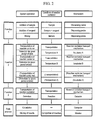
Fig. 1 is a schematic flow diagram illustrating analysis operations in the examples. -
Fig. 2 is a schematic flow diagram illustrating operations of an automatic analyzer in the examples. -
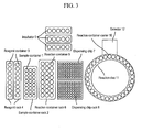
Fig. 3 schematically illustrates the basic construction of an automatic analyzer in the examples. -
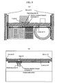
Fig. 4 schematically illustrates a reaction container transport mechanism or the like in the examples. -
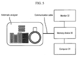
Fig. 5 schematically shows the correlation between an automatic analyzer and peripheral devices in the examples. - The examples disclose an analysis method requiring two or more temperature changes in the process of sample preparation (i.e., the process of reaction solution preparation) with the use of two or more different incubators set at temperatures required for assays, a dispensing probe for preparing a sample, and a detector for detecting a target substance, wherein the method performs analysis by at least the following 3 steps.
-
- 1) A step of preparing a reaction solution by mixing a sample and a reagent with the use of a dispensing probe;
- 2) a step of transporting a reaction container between two or more incubators set at temperatures required for assays to perform temperature changes in the process of reaction solution preparation; and
- 3) a step of detecting a target substance (a target nucleic acid).
- The examples disclose an automatic analyzer used for an analysis method requiring two or more temperature changes in the process of reaction solution preparation, which comprises two or more different incubators set at temperatures required for assays, a dispensing probe for preparing a sample, a mechanism for transporting a reaction container, and a detector for detecting a target nucleic acid, and it analyzes a sample by making use of at least the following 3 functions.
-
- 1) A function of preparing a reaction solution by mixing a sample and a reagent with the use of a dispensing probe;
- 2) a function of transporting a reaction container between incubators set at temperatures required for assays by means of a mechanism for transporting a reaction container; and
- 3) a function of detecting a target nucleic acid with a detector.
- Any detector may be used to detect a target nucleic acid, provided that reaction containers can be continuously introduced and analytical reactions in the reaction containers can be detected. A preferable detector is that of a rotary-disc system, and it allows reaction containers to be continuously introduced thereinto from a given position. A more preferable detector is capable of detecting the reaction process with the elapse of time and automatically discarding reaction containers after the completion of detection. The detection method and the detection mechanism of the detector vary depending on analysis method, and any method and mechanism may be employed, provided that they allow a target nucleic acid to be qualitatively or quantitatively detected.
- The examples disclose a nucleic acid analyzer comprising: a plurality of reaction containers that can contain nucleic-acid-containing samples and reagents; a plurality of incubation mechanisms that can control the temperatures of reaction containers set at different levels; an analysis mechanism that analyzes the samples contained in reaction containers; a transport mechanism that transports reaction containers to a given incubation mechanism; and a control mechanism that controls the transport mechanism. The transport mechanism transports reaction containers to a given incubation mechanism in a given order in accordance with the assay to be performed on a nucleic-acid-containing sample of interest.
- The examples also disclose an analysis method using a nucleic acid analyzer, wherein a plurality of incubation mechanisms that can control the temperatures of reaction containers set at different levels and reaction containers that contain nucleic-acid-containing samples and reagents are prepared;
the reaction container is transported to an incubation mechanism of interest in accordance with the assay technique to be performed on the nucleic-acid-containing sample, the incubation mechanism controls the temperature of the reaction container, the reaction container is transported to another incubation mechanism of interest, the incubation mechanism controls the temperature of the reaction container so as to maintain it at a different level, and the reaction container is transported to the incubation mechanism in the order as desired to change the temperature of the sample as desired; and
the reaction container is transported to the analysis mechanism to analyze the sample. - The examples disclose that the analysis mechanism is capable of detecting the analytical reaction of a sample with the elapse of time.
- The examples disclose that the analysis mechanism comprises a rotary disc capable of containing a plurality of reaction containers.
- The examples also disclose that the transport mechanism transports a reaction container to an incubation mechanism and an analysis mechanism of interest.
- In addition, the examples disclose that the sample and the reagent contained in the reaction container are agitated.
- The examples disclose that the temperature of the reaction container is controlled by the incubation mechanism, and the sample and the reagent are then agitated.
- Also, the examples disclose that, depending on the temperature of the sample before it has been transported to the incubation mechanism, the duration during which the reaction container containing such sample is controlled by the incubation mechanism is altered.
- Further, the examples disclose that, depending on the incubation mechanism to which the reaction container was transported before it has been transported to the analysis mechanism, the duration of transportation from the incubation mechanism to the analytical mechanism is altered.
- Hereafter, the novel characteristics and effects of the present invention are described in detail with reference to the drawings, although the technical scope of the present invention is not limited to concrete examples provided below.
- This example involves the use of a dispensing probe for preparing a sample, two or more different incubators set at temperatures required for assays, and a detector for detecting a target substance.
- Any dispensing probe may be used for sample preparation, provided that it can accurately dispense the sample and the reagent. Use of an exchangeable and removable dispensing chip is preferable for the purpose of prevention of sample contamination. Specific examples include Pipetman pipettes (Gilson) and electronic pipettes (Biohit).
- Any incubators may be used as the two or more different incubators set at temperatures required for assays, provided that the reaction containers are capable of adhering to the incubator within the range of the reaction solutions, and the temperature can be set at a level required for assays. When the target temperature is higher than room temperature, a heating incubator is used. When the target temperature is lower than room temperature, a cooling incubator is used.
- Any detector may be used for detecting a target substance, provided that such detector is capable of detecting a target substance. The detection method and the detection mechanism of the detector vary depending on analysis method. More preferably, a detector is capable of detecting the analytical reaction in the reaction container with the elapse of time. When fluorescence emission is to be analyzed, specifically, the detector is composed of an excitation light applicator for exciting fluorescence emission and a sensor for detecting excited light, so as to detect fluorescence emission.
- This example involves the use of above 3 forms of equipment and implementation of the following 3 processes to analyze the target substance.
-
- 1) A step of preparing a reaction solution by mixing a sample and a reagent with the use of a dispensing probe;
- 2) a step of transporting a reaction container between two or more incubators set at temperatures required for assays to perform temperature changes in the process of reaction solution preparation; and
- 3) a step of detecting a target substance.
- In
Step 1, a sample container containing a test sample derived from a biological sample is used. The sample is removed from the sample container with the use of a dispensing probe and dispensed into a reaction container. Subsequently, a reagent is removed from a reagent container and dispensed into a reaction container. The sample and the reagent are then mixed by repeating suction and ejection with a dispensing probe in the reaction container. More preferably, a dispensing chip is exchanged with another chip for each sample or reagent dispensing operation in order to prevent the sample or reagent from contamination. In this process, the sample container can be used as a reaction container, as long as the amount of the sample in the sample container is large enough for detection. In such a case, the process of removing the sample from the sample container and dispensing the same into reaction container can be omitted. Also, mixing may be carried out in the reaction container with the use of a mixing agitator. - The term "biological sample" used herein refers to a sample obtained by physical examination, such as health screening, medical check-up, multiphasic health screening, or health screening by mail; a biological sample containing the target substance in the blood, tissue, or urine of an outpatient or inpatient obtained at a hospital; and a sample to which such biological sample is adhered.
- The term "target substance" used herein refers to a component derived from any organism (including a virus or a microorganism), and the term preferably refers to a protein, a peptide, an amino acid, or a nucleic acid. A test sample may be obtained by subjecting a biological sample to a pretreatment such as purification. A specific example of the pretreatment is, when the target substance is a viral nucleic acid, purification of such nucleic acid from a biological sample. For example, a nucleic acid component is separated from a protein component with the use of phenol and chloroform to purify a nucleic acid. Alternatively, a nucleic acid is allowed to adsorb to a silica column, washed, and then eluted from the silica column with the use of a nucleic-acid-dissolving solution. Thus, a nucleic acid is purified.
- As the sample container, the reaction container, and the reagent container used herein, any container may be used, provided that components of the container are not transferred to the sample, the reagent, or the reaction solution. Preferably, a transparent polypropylene container is used. Specific examples include a 1.5-ml Eppendorf tube (Eppendorf) and a 0.2-ml PCR tube.
-
Step 2 is a process of transporting a reaction container between two or more incubators to rapidly change the temperature of the reaction solution in accordance with the temperature conditions required for the analysis method. When the temperature conditions are 37°C for 15 minutes, 95°C for 5 minutes, and 41°C for 2 minutes, more specifically, three types of incubators at 37°C, 95°C, and 41°C are prepared. At the outset, the reaction container is introduced into an incubator at 37°C and retained therein for 15 minutes. Subsequently, the reaction container is transferred to an incubator at 95°C and retained therein for 5 minutes. Finally, the reaction container is transferred to an incubator at 41°C and retained therein for 2 minutes. The retention time is preferably prolonged by taking the time required for the temperature of the solution to reach the target level after transportation into consideration. Such time varies depending on differences in temperature changes, and the time required to reach the target temperature is as shown in Table 1 according to the results of the experiment conducted by the present inventors. Also, such temperature changes may occasionally cause the reaction solution to evaporate. The reaction solution can be prevented from evaporating by a method involving the addition of oil or a conventional method involving covering the reaction container and heating the cover.Table 1 Time required to reach target temperature Temperature before transportation Target temperature Time (sec.) 28°C 65°C 42 28°C 37°C 44 37°C 95°C 116 65°C 41°C 44 95°C 41°C 100 -
Step 3 involves detection of the reaction with a detector. Any method may be employed in this step, provided that it allows a target substance to be detected in accordance with an analysis method. Preferably, the reaction containers are rotated with the use of a rotary disc to continuously analyze a plurality of reaction containers, and detection is carried out with the use of a detector in accordance with the rotation cycle. More preferably, the reaction is detected with the elapse of time. - According to this example, reaction containers can be subjected to continuous analysis even when assays involving different temperature changes during the process of preparation of sample solutions or assays involving different reaction or detection time or detection intervals are performed. Also, the processes for preparing samples can be completely synchronized. Further, temperature can be changed more rapidly than is possible with a conventional technique.
- In this example, an automatic analyzer that automatically performs the analysis described in Example 1 is described. The automatic analyzer of this example is an apparatus that automatically implements an analysis method requiring two or more temperature changes in the process of reaction solution preparation, which is realized by the operations of the apparatus shown in
Fig. 2 and the constitution of the apparatus shown inFigs. 3 and4 . Hereafter, the automatic analyzer is described in detail with reference toFigs. 2 to 5 mainly in comparison with Example 1. -
Fig. 3 shows the basic construction of the automatic analyzer used herein, except for the dispensing probe and the reaction container transport mechanism. This apparatus comprises: asample container rack 2 that can comprise asample container 1 accommodating the test sample mounted thereon; areagent rack 4 that accommodates a plurality ofreagent containers 3 comprising a reagent reacting with various component of the sample; areaction container rack 6 that accommodates areaction container 5 used for mixing the sample with the reagent; adispensing chip rack 8 that accommodates adispensing chip 7; a plurality ofincubators 9 set at two or more different temperatures; areaction disc 11 that comprises a plurality ofreaction container carriers 10 positioned around the circumference thereof; and adetector 12 that detects the reaction. -
Fig. 4(a) and Fig. 4(b) are schematic diagrams illustrating a dispensingprobe 20 for dispensing a sample or reagent between racks, a reactioncontainer transport mechanism 21 for transporting a reaction container, ahead 22 for connecting the same, and aside rail 23 and acenter rail 24 for moving the head toward the X axis and the Y axis. - The automatic analyzer according to this example automatically analyzes a sample by the operations shown in
Fig. 2 . Specifically, the dispensingprobe 20 moves to the position of thedispensing chip rack 8 via the motion of theside rail 23 and thecenter rail 24 and mounts thedispensing chip 7. The dispensingprobe 20 on which thedispensing chip 7 had been mounted removes a sample from thesample container 1 and discharges the sample into thereaction container 5. Subsequently, thedispensing chip 7 is exchanged with a fresh chip, the reagent is removed from thereagent container 3 and discharged into thereaction container 5, and the dispensingprobe 20 mixes the reaction solution via repetition of suction and ejection. Thereaction container 5 containing the reaction solution is transferred to one of theincubators 9 by the reactioncontainer transport mechanism 21, and the temperature of the reaction solution is changed. After the reaction container has been retained in an incubator for a given period of time, it is transferred to anotherincubator 9 by the reaction container transport mechanism, the temperature of the reaction solution is changed, and the resultant is also retained in an incubator for a given period of time. Transportation between incubators is carried out under conditions designated for the relevant analysis method. In accordance with the designated analysis method, the dispensingprobe 20 with thedispensing chip 7 mounted thereon may remove a reagent from thereagent container 3 and discharge the reagent into thereaction container 5 after or during the process of temperature changes between the incubators. After temperature has been changed, the reactioncontainer transport mechanism 21 introduces thereaction container 5 into thereaction container carrier 10 positioned within thereaction disc 11. The temperature of thereaction container carrier 10 is maintained at a level at which the reaction proceeds in the most effective manner. Such reaction is detected by thedetector 12. More preferably, thedetector 12 detects the reaction with the elapse of time in accordance with the cell cycle of thereaction disc 11. -
Fig. 5 shows the correlation between the automatic analyzer and peripheral devices. This automatic analyzer comprises amemory device 30 that stores the detection data, acomputer 31 that computes the stored detection data, and amonitor 32 that displays the results of computation connected thereto. Such peripheral devices may be connected to the automatic analyzer via a connecting cable 33 and they may function independently. Alternatively, such peripheral devices may be built into the automatic analyzer. - As operations of the apparatus, including the post-treatment, the detection data detected by the
detector 12 are transferred to thememory device 30, the data are computed by thecomputer 31, and the results of detection are displayed on themonitor 32. - The above examples disclose a transport mechanism that transports both the dispensing probe and the reaction container. The dispensing probe and the reaction container may be handled by different transport mechanisms. While the above examples involve the use of a single transport mechanism, a plurality of transport mechanisms may be provided, so as to cope with the use of a plurality of incubation mechanisms or analysis mechanisms, according to need.
-
- 1: Sample container
- 2: Sample container rack
- 3: Reagent container
- 4: Reagent rack
- 5: Reaction container
- 6: Reaction container rack
- 7: Dispensing chip
- 8: Dispensing chip rack
- 9: Incubator
- 10: Reaction container carrier
- 11: Reaction disc
- 12: Detector
- 20: Dispensing probe
- 21: Reaction container transport mechanism
- 22: Head
- 23: Side rail
- 24: Center rail
- 30: Memory device
- 31: Computer
- 32: Monitor
- 33: Connecting cable
Claims (20)
- A nucleic acid analyzer comprising:a plurality of reaction containers capable of containing nucleic-acid-containing samples and reagents;a plurality of incubation mechanisms capable of controlling the temperatures of reaction containers set at different levels;an analysis mechanism for analyzing the samples contained in the reaction containers;a transport mechanism for transporting a reaction container to a given incubation mechanism; anda control mechanism for controlling the transport mechanism,the transport mechanism transporting a reaction container to a given incubation mechanism in a given order in accordance with the assay technique to be performed on a nucleic-acid-containing sample.
- The nucleic acid analyzer according to claim 1, wherein the analysis mechanism is capable of detecting an analytical reaction of the sample with the elapse of time.
- The nucleic acid analyzer according to claim 1, wherein the analysis mechanism comprises a rotary disc capable of containing a plurality of reaction containers.
- The nucleic acid analyzer according to claim 1, wherein the transport mechanism transports a reaction container to an incubation mechanism and an analysis mechanism of interest.
- The nucleic acid analyzer according to claim 1, wherein the sample and the reagent contained in the reaction container are agitated.
- The nucleic acid analyzer according to claim 5, wherein the temperature of the reaction container is controlled by the incubation mechanism, and the sample and the reagent are then agitated.
- The nucleic acid analyzer according to claim 1, wherein, depending on the temperature of the sample before it has been transported to the incubation mechanism, the duration during which the reaction container containing the sample is controlled by the incubation mechanism is altered.
- The nucleic acid analyzer according to claim 1, wherein, depending on the incubation mechanism to which the reaction container was transported before it has been transported to the analysis mechanism, the duration of transportation from the incubation mechanism to the analytical mechanism is altered.
- An analysis method using a nucleic acid analyzer, wherein a plurality of incubation mechanisms that can control the temperatures of reaction containers set at different levels and reaction containers that contain nucleic-acid-containing samples and reagents are prepared;
the reaction container is transported to an incubation mechanism of interest in accordance with the assay technique to be performed on the nucleic-acid-containing sample, the incubation mechanism controls the temperature of the reaction container, the reaction container is transported to another incubation mechanism of interest, the incubation mechanism controls the temperature of the reaction container so as to maintain it at a different level, and the reaction container is transported to the incubation mechanism in the order as desired to change the temperature of the sample as desired; and
the reaction container is transported to the analysis mechanism to analyze the sample. - The analysis method according to claim 9, wherein the analysis mechanism detects the analytical reaction of the sample with the elapse of time.
- The analysis method according to claim 9, wherein the analysis mechanism comprises a rotary disc capable of containing a plurality of reaction containers.
- The analysis method according to claim 9, wherein the sample and the reagent contained in the reaction container are agitated.
- The analysis method according to claim 12, wherein the temperature of the reaction container is controlled by the incubation mechanism, and the sample and the reagent are then agitated.
- The analysis method according to claim 9, wherein, depending on the temperature of the sample before it has been transported to the incubation mechanism, the duration during which the reaction container containing the sample is controlled by the incubation mechanism is altered.
- The analysis method according to claim 9, wherein, depending on the incubation mechanism to which the reaction container was transported before it has been transported to the analysis mechanism, the duration of transportation from the incubation mechanism to the analytical mechanism is altered.
- An analysis method requiring two or more temperature changes in the process of sample preparation comprising:preparing two or more different incubators set at temperatures required for assays, a dispensing probe for preparing a sample, and a detector for detecting a target substance;preparing a reaction solution by mixing a sample and a reagent with the use of a dispensing probe;transporting a reaction container between two or more incubators set at temperatures required for assays to perform temperature changes in the process of reaction solution preparation; anddetecting a target substance.
- The analysis method according to claim 16, wherein the sample is mixed with the reagent before and after the temperature is changed.
- An automatic analyzer used for implementing an analysis method requiring two or more temperature changes in the process of reaction solution preparation comprising:two or more different incubators set at temperatures required for assays;a dispensing probe for preparing a sample;a mechanism for transporting a reaction container; anda detector for detecting a target substance,the analyzer having:a function of preparing a reaction solution by mixing a sample and a reagent with the use of a dispensing probe;a function of transporting a reaction container between incubators set at temperatures required for assays by means of a mechanism for transporting a reaction container; anda function of detecting a target nucleic acid with a detector.
- The automatic analyzer according to claim 18, wherein use of the detector in combination with a rotary disc enables continuous introduction of reaction containers.
- The automatic analyzer according to claim 18, which is capable of detecting the analytical reaction with the elapse of time.
Applications Claiming Priority (2)
| Application Number | Priority Date | Filing Date | Title |
|---|---|---|---|
| JP2008162669A JP5372418B2 (en) | 2008-06-23 | 2008-06-23 | Nucleic acid analyzer, automatic analyzer, and analysis method |
| PCT/JP2009/061004 WO2009157353A1 (en) | 2008-06-23 | 2009-06-17 | Nucleic acid analyzer, automatic analyzer, and analysis method |
Publications (3)
| Publication Number | Publication Date |
|---|---|
| EP2306204A1 true EP2306204A1 (en) | 2011-04-06 |
| EP2306204A4 EP2306204A4 (en) | 2017-11-29 |
| EP2306204B1 EP2306204B1 (en) | 2021-08-11 |
Family
ID=41444421
Family Applications (1)
| Application Number | Title | Priority Date | Filing Date |
|---|---|---|---|
| EP09770063.7A Active EP2306204B1 (en) | 2008-06-23 | 2009-06-17 | Nucleic acid analyzer, automatic analyzer, and analysis method |
Country Status (5)
| Country | Link |
|---|---|
| US (1) | US8574891B2 (en) |
| EP (1) | EP2306204B1 (en) |
| JP (1) | JP5372418B2 (en) |
| CN (1) | CN102066950B (en) |
| WO (1) | WO2009157353A1 (en) |
Cited By (3)
| Publication number | Priority date | Publication date | Assignee | Title |
|---|---|---|---|---|
| EP2597143A4 (en) * | 2010-07-21 | 2014-05-14 | Hitachi High Tech Corp | METHOD FOR DETECTION OF NUCLEIC ACID AMPLIFICATION IN SAMPLE AND DEVICE THEREFOR |
| WO2015086446A1 (en) * | 2013-12-13 | 2015-06-18 | Sotax Ag | Apparatus for dissolution testing |
| EP2600156B1 (en) * | 2010-07-28 | 2022-04-20 | Hitachi High-Tech Corporation | Nucleic acid analysis device |
Families Citing this family (10)
| Publication number | Priority date | Publication date | Assignee | Title |
|---|---|---|---|---|
| KR101368463B1 (en) * | 2010-04-23 | 2014-03-03 | 나노바이오시스 주식회사 | Device for amplify nucleic acid comprising two heating block |
| JP5249988B2 (en) * | 2010-05-07 | 2013-07-31 | 株式会社日立ハイテクノロジーズ | Nucleic acid amplification apparatus and nucleic acid test apparatus using the same |
| JP5662055B2 (en) * | 2010-05-14 | 2015-01-28 | 株式会社日立ハイテクノロジーズ | Nucleic acid amplification apparatus and nucleic acid amplification method |
| JP5689274B2 (en) * | 2010-10-05 | 2015-03-25 | 株式会社日立ハイテクノロジーズ | Nucleic acid test apparatus and container transport method |
| JP5722001B2 (en) * | 2010-11-10 | 2015-05-20 | 株式会社日立ハイテクノロジーズ | Genetic testing method and testing device |
| JP5789441B2 (en) * | 2011-08-01 | 2015-10-07 | 株式会社日立ハイテクノロジーズ | Genetic testing system |
| WO2017183298A1 (en) * | 2016-04-20 | 2017-10-26 | シスメックス株式会社 | Nucleic acid analysis device and nucleic acid analysis method |
| CN109313207B (en) * | 2016-05-25 | 2022-07-19 | 环球生物研究株式会社 | Sample processing and measuring system |
| CN106967585B (en) * | 2017-05-23 | 2024-03-12 | 湖州师范学院 | Integrated equipment for nucleic acid extraction and detection |
| CN113930331A (en) * | 2021-10-09 | 2022-01-14 | 苏州国科均豪生物科技有限公司 | Incubation temperature control method, medium, PCR detection system for fluorescence immunoassay analyzer |
Family Cites Families (16)
| Publication number | Priority date | Publication date | Assignee | Title |
|---|---|---|---|---|
| US5038852A (en) | 1986-02-25 | 1991-08-13 | Cetus Corporation | Apparatus and method for performing automated amplification of nucleic acid sequences and assays using heating and cooling steps |
| CA1339653C (en) * | 1986-02-25 | 1998-02-03 | Larry J. Johnson | Appartus and method for performing automated amplification of nucleic acid sequences and assays using heating and cooling steps |
| JPS6385361A (en) * | 1986-09-30 | 1988-04-15 | Toshiba Corp | Automatic chemical analyser |
| JPH03262499A (en) * | 1990-03-12 | 1991-11-22 | Kosumitsuku:Kk | Detection of polynucleotide and pcr reacting device |
| JPH06281655A (en) | 1993-03-25 | 1994-10-07 | Olympus Optical Co Ltd | Automatic analyzer |
| JP3113446B2 (en) | 1993-03-26 | 2000-11-27 | 三洋電機株式会社 | incubator |
| JPH08196299A (en) | 1995-01-26 | 1996-08-06 | Tosoh Corp | Thermal cycling reactor and reaction vessel used therefor |
| JPH08271524A (en) | 1995-03-31 | 1996-10-18 | Suzuki Motor Corp | Enzyme immunoreaction measuring device |
| US5795748A (en) * | 1996-09-26 | 1998-08-18 | Becton Dickinson And Company | DNA microwell device and method |
| US6413780B1 (en) | 1998-10-14 | 2002-07-02 | Abbott Laboratories | Structure and method for performing a determination of an item of interest in a sample |
| FR2812306B1 (en) * | 2000-07-28 | 2005-01-14 | Gabriel Festoc | POLYMERSIS CHAIN AMPLIFICATION SYSTEM OF TARGET NUCLEIC SEQUENCES |
| JP2003050242A (en) * | 2001-08-08 | 2003-02-21 | Hitachi Ltd | Biological sample processing equipment |
| JP2005069902A (en) * | 2003-08-26 | 2005-03-17 | Hitachi Instruments Service Co Ltd | Pretreatment device |
| JP2005125311A (en) * | 2003-09-30 | 2005-05-19 | Japan Science & Technology Agency | Chemical reactor |
| US7794659B2 (en) * | 2005-03-10 | 2010-09-14 | Gen-Probe Incorporated | Signal measuring system having a movable signal measuring device |
| JP5638806B2 (en) * | 2006-11-03 | 2014-12-10 | シーメンス・ヘルスケア・ダイアグノスティックス・インコーポレーテッドSiemens Healthcare Diagnostics Inc. | Random access system and method for polymerase chain reaction testing |
-
2008
- 2008-06-23 JP JP2008162669A patent/JP5372418B2/en not_active Expired - Fee Related
-
2009
- 2009-06-17 CN CN200980123709.8A patent/CN102066950B/en not_active Expired - Fee Related
- 2009-06-17 US US13/000,579 patent/US8574891B2/en not_active Expired - Fee Related
- 2009-06-17 EP EP09770063.7A patent/EP2306204B1/en active Active
- 2009-06-17 WO PCT/JP2009/061004 patent/WO2009157353A1/en not_active Ceased
Non-Patent Citations (1)
| Title |
|---|
| See references of WO2009157353A1 * |
Cited By (4)
| Publication number | Priority date | Publication date | Assignee | Title |
|---|---|---|---|---|
| EP2597143A4 (en) * | 2010-07-21 | 2014-05-14 | Hitachi High Tech Corp | METHOD FOR DETECTION OF NUCLEIC ACID AMPLIFICATION IN SAMPLE AND DEVICE THEREFOR |
| EP2600156B1 (en) * | 2010-07-28 | 2022-04-20 | Hitachi High-Tech Corporation | Nucleic acid analysis device |
| WO2015086446A1 (en) * | 2013-12-13 | 2015-06-18 | Sotax Ag | Apparatus for dissolution testing |
| US10184874B2 (en) | 2013-12-13 | 2019-01-22 | Sotax Ag | Apparatus for dissolution testing |
Also Published As
| Publication number | Publication date |
|---|---|
| CN102066950B (en) | 2014-12-17 |
| EP2306204A4 (en) | 2017-11-29 |
| US8574891B2 (en) | 2013-11-05 |
| US20110104703A1 (en) | 2011-05-05 |
| CN102066950A (en) | 2011-05-18 |
| EP2306204B1 (en) | 2021-08-11 |
| JP5372418B2 (en) | 2013-12-18 |
| WO2009157353A1 (en) | 2009-12-30 |
| JP2010002353A (en) | 2010-01-07 |
Similar Documents
| Publication | Publication Date | Title |
|---|---|---|
| EP2306204B1 (en) | Nucleic acid analyzer, automatic analyzer, and analysis method | |
| CN113413938B (en) | Method of operating assay system and ECL immunoassay system | |
| CN110564607B (en) | Full-automatic nucleic acid extraction amplification micro-fluidic chip dynamic quantitative detection integrated device | |
| US11098343B2 (en) | Systems and methods for performing assays | |
| JP4125735B2 (en) | Modular equipment | |
| KR101917402B1 (en) | Automatic response/light measurement device and method therefor | |
| US20120100600A1 (en) | Apparatus for polynucleotide detection and quantitation | |
| EP2392929B1 (en) | Analyzer, and control method for rotation of disc | |
| WO2006002960A1 (en) | Instrument for efficient treatment of analytical devices | |
| JPWO2012157685A1 (en) | Photometric device for reaction vessel and method thereof | |
| US8175810B2 (en) | Sample processing apparatus and sample processing method | |
| CN119640412A (en) | Nucleic acid sequencing pretreatment workstation and sequencing pretreatment method | |
| US20030069699A1 (en) | Device for drug-drug interaction testing sample preparation | |
| JP6184806B2 (en) | Automated method for disposing of chips in an automated processing module and processing system comprising a processing module | |
| US11654437B2 (en) | Assay cartridg for molecular diagnosis | |
| JP4328788B2 (en) | Nucleic acid sample testing equipment | |
| JPH06225752A (en) | DNA probe automatic measuring device and method for measuring nucleic acid in sample | |
| EP1772192B1 (en) | Biochemical processing apparatus provided with liquid transport mechanism |
Legal Events
| Date | Code | Title | Description |
|---|---|---|---|
| PUAI | Public reference made under article 153(3) epc to a published international application that has entered the european phase |
Free format text: ORIGINAL CODE: 0009012 |
|
| 17P | Request for examination filed |
Effective date: 20110114 |
|
| AK | Designated contracting states |
Kind code of ref document: A1 Designated state(s): AT BE BG CH CY CZ DE DK EE ES FI FR GB GR HR HU IE IS IT LI LT LU LV MC MK MT NL NO PL PT RO SE SI SK TR |
|
| AX | Request for extension of the european patent |
Extension state: AL BA RS |
|
| DAX | Request for extension of the european patent (deleted) | ||
| RA4 | Supplementary search report drawn up and despatched (corrected) |
Effective date: 20171103 |
|
| RIC1 | Information provided on ipc code assigned before grant |
Ipc: C12M 1/00 20060101ALI20171026BHEP Ipc: G01N 35/04 20060101ALI20171026BHEP Ipc: C12M 1/34 20060101ALI20171026BHEP Ipc: G01N 35/10 20060101ALI20171026BHEP Ipc: G01N 35/00 20060101ALI20171026BHEP Ipc: C12Q 1/68 20060101ALI20171026BHEP Ipc: G01N 35/02 20060101AFI20171026BHEP Ipc: G01N 33/50 20060101ALI20171026BHEP |
|
| RAP1 | Party data changed (applicant data changed or rights of an application transferred) |
Owner name: HITACHI HIGH-TECH CORPORATION |
|
| STAA | Information on the status of an ep patent application or granted ep patent |
Free format text: STATUS: EXAMINATION IS IN PROGRESS |
|
| 17Q | First examination report despatched |
Effective date: 20201029 |
|
| GRAP | Despatch of communication of intention to grant a patent |
Free format text: ORIGINAL CODE: EPIDOSNIGR1 |
|
| STAA | Information on the status of an ep patent application or granted ep patent |
Free format text: STATUS: GRANT OF PATENT IS INTENDED |
|
| INTG | Intention to grant announced |
Effective date: 20210319 |
|
| GRAS | Grant fee paid |
Free format text: ORIGINAL CODE: EPIDOSNIGR3 |
|
| GRAA | (expected) grant |
Free format text: ORIGINAL CODE: 0009210 |
|
| STAA | Information on the status of an ep patent application or granted ep patent |
Free format text: STATUS: THE PATENT HAS BEEN GRANTED |
|
| AK | Designated contracting states |
Kind code of ref document: B1 Designated state(s): AT BE BG CH CY CZ DE DK EE ES FI FR GB GR HR HU IE IS IT LI LT LU LV MC MK MT NL NO PL PT RO SE SI SK TR |
|
| REG | Reference to a national code |
Ref country code: GB Ref legal event code: FG4D |
|
| REG | Reference to a national code |
Ref country code: CH Ref legal event code: EP |
|
| REG | Reference to a national code |
Ref country code: DE Ref legal event code: R096 Ref document number: 602009063950 Country of ref document: DE |
|
| REG | Reference to a national code |
Ref country code: IE Ref legal event code: FG4D Ref country code: AT Ref legal event code: REF Ref document number: 1419909 Country of ref document: AT Kind code of ref document: T Effective date: 20210915 |
|
| REG | Reference to a national code |
Ref country code: LT Ref legal event code: MG9D |
|
| REG | Reference to a national code |
Ref country code: NL Ref legal event code: MP Effective date: 20210811 |
|
| REG | Reference to a national code |
Ref country code: AT Ref legal event code: MK05 Ref document number: 1419909 Country of ref document: AT Kind code of ref document: T Effective date: 20210811 |
|
| PG25 | Lapsed in a contracting state [announced via postgrant information from national office to epo] |
Ref country code: HR Free format text: LAPSE BECAUSE OF FAILURE TO SUBMIT A TRANSLATION OF THE DESCRIPTION OR TO PAY THE FEE WITHIN THE PRESCRIBED TIME-LIMIT Effective date: 20210811 Ref country code: SE Free format text: LAPSE BECAUSE OF FAILURE TO SUBMIT A TRANSLATION OF THE DESCRIPTION OR TO PAY THE FEE WITHIN THE PRESCRIBED TIME-LIMIT Effective date: 20210811 Ref country code: LT Free format text: LAPSE BECAUSE OF FAILURE TO SUBMIT A TRANSLATION OF THE DESCRIPTION OR TO PAY THE FEE WITHIN THE PRESCRIBED TIME-LIMIT Effective date: 20210811 Ref country code: BG Free format text: LAPSE BECAUSE OF FAILURE TO SUBMIT A TRANSLATION OF THE DESCRIPTION OR TO PAY THE FEE WITHIN THE PRESCRIBED TIME-LIMIT Effective date: 20211111 Ref country code: AT Free format text: LAPSE BECAUSE OF FAILURE TO SUBMIT A TRANSLATION OF THE DESCRIPTION OR TO PAY THE FEE WITHIN THE PRESCRIBED TIME-LIMIT Effective date: 20210811 Ref country code: FI Free format text: LAPSE BECAUSE OF FAILURE TO SUBMIT A TRANSLATION OF THE DESCRIPTION OR TO PAY THE FEE WITHIN THE PRESCRIBED TIME-LIMIT Effective date: 20210811 Ref country code: ES Free format text: LAPSE BECAUSE OF FAILURE TO SUBMIT A TRANSLATION OF THE DESCRIPTION OR TO PAY THE FEE WITHIN THE PRESCRIBED TIME-LIMIT Effective date: 20210811 Ref country code: NO Free format text: LAPSE BECAUSE OF FAILURE TO SUBMIT A TRANSLATION OF THE DESCRIPTION OR TO PAY THE FEE WITHIN THE PRESCRIBED TIME-LIMIT Effective date: 20211111 Ref country code: PT Free format text: LAPSE BECAUSE OF FAILURE TO SUBMIT A TRANSLATION OF THE DESCRIPTION OR TO PAY THE FEE WITHIN THE PRESCRIBED TIME-LIMIT Effective date: 20211213 |
|
| PG25 | Lapsed in a contracting state [announced via postgrant information from national office to epo] |
Ref country code: PL Free format text: LAPSE BECAUSE OF FAILURE TO SUBMIT A TRANSLATION OF THE DESCRIPTION OR TO PAY THE FEE WITHIN THE PRESCRIBED TIME-LIMIT Effective date: 20210811 Ref country code: LV Free format text: LAPSE BECAUSE OF FAILURE TO SUBMIT A TRANSLATION OF THE DESCRIPTION OR TO PAY THE FEE WITHIN THE PRESCRIBED TIME-LIMIT Effective date: 20210811 Ref country code: GR Free format text: LAPSE BECAUSE OF FAILURE TO SUBMIT A TRANSLATION OF THE DESCRIPTION OR TO PAY THE FEE WITHIN THE PRESCRIBED TIME-LIMIT Effective date: 20211112 |
|
| PG25 | Lapsed in a contracting state [announced via postgrant information from national office to epo] |
Ref country code: NL Free format text: LAPSE BECAUSE OF FAILURE TO SUBMIT A TRANSLATION OF THE DESCRIPTION OR TO PAY THE FEE WITHIN THE PRESCRIBED TIME-LIMIT Effective date: 20210811 |
|
| PG25 | Lapsed in a contracting state [announced via postgrant information from national office to epo] |
Ref country code: DK Free format text: LAPSE BECAUSE OF FAILURE TO SUBMIT A TRANSLATION OF THE DESCRIPTION OR TO PAY THE FEE WITHIN THE PRESCRIBED TIME-LIMIT Effective date: 20210811 |
|
| REG | Reference to a national code |
Ref country code: DE Ref legal event code: R097 Ref document number: 602009063950 Country of ref document: DE |
|
| PG25 | Lapsed in a contracting state [announced via postgrant information from national office to epo] |
Ref country code: SK Free format text: LAPSE BECAUSE OF FAILURE TO SUBMIT A TRANSLATION OF THE DESCRIPTION OR TO PAY THE FEE WITHIN THE PRESCRIBED TIME-LIMIT Effective date: 20210811 Ref country code: RO Free format text: LAPSE BECAUSE OF FAILURE TO SUBMIT A TRANSLATION OF THE DESCRIPTION OR TO PAY THE FEE WITHIN THE PRESCRIBED TIME-LIMIT Effective date: 20210811 Ref country code: EE Free format text: LAPSE BECAUSE OF FAILURE TO SUBMIT A TRANSLATION OF THE DESCRIPTION OR TO PAY THE FEE WITHIN THE PRESCRIBED TIME-LIMIT Effective date: 20210811 Ref country code: CZ Free format text: LAPSE BECAUSE OF FAILURE TO SUBMIT A TRANSLATION OF THE DESCRIPTION OR TO PAY THE FEE WITHIN THE PRESCRIBED TIME-LIMIT Effective date: 20210811 |
|
| PLBE | No opposition filed within time limit |
Free format text: ORIGINAL CODE: 0009261 |
|
| STAA | Information on the status of an ep patent application or granted ep patent |
Free format text: STATUS: NO OPPOSITION FILED WITHIN TIME LIMIT |
|
| 26N | No opposition filed |
Effective date: 20220512 |
|
| PG25 | Lapsed in a contracting state [announced via postgrant information from national office to epo] |
Ref country code: IT Free format text: LAPSE BECAUSE OF FAILURE TO SUBMIT A TRANSLATION OF THE DESCRIPTION OR TO PAY THE FEE WITHIN THE PRESCRIBED TIME-LIMIT Effective date: 20210811 |
|
| PG25 | Lapsed in a contracting state [announced via postgrant information from national office to epo] |
Ref country code: SI Free format text: LAPSE BECAUSE OF FAILURE TO SUBMIT A TRANSLATION OF THE DESCRIPTION OR TO PAY THE FEE WITHIN THE PRESCRIBED TIME-LIMIT Effective date: 20210811 |
|
| PG25 | Lapsed in a contracting state [announced via postgrant information from national office to epo] |
Ref country code: MC Free format text: LAPSE BECAUSE OF FAILURE TO SUBMIT A TRANSLATION OF THE DESCRIPTION OR TO PAY THE FEE WITHIN THE PRESCRIBED TIME-LIMIT Effective date: 20210811 |
|
| REG | Reference to a national code |
Ref country code: CH Ref legal event code: PL |
|
| REG | Reference to a national code |
Ref country code: BE Ref legal event code: MM Effective date: 20220630 |
|
| PG25 | Lapsed in a contracting state [announced via postgrant information from national office to epo] |
Ref country code: LU Free format text: LAPSE BECAUSE OF NON-PAYMENT OF DUE FEES Effective date: 20220617 Ref country code: LI Free format text: LAPSE BECAUSE OF NON-PAYMENT OF DUE FEES Effective date: 20220630 Ref country code: IE Free format text: LAPSE BECAUSE OF NON-PAYMENT OF DUE FEES Effective date: 20220617 Ref country code: CH Free format text: LAPSE BECAUSE OF NON-PAYMENT OF DUE FEES Effective date: 20220630 |
|
| PG25 | Lapsed in a contracting state [announced via postgrant information from national office to epo] |
Ref country code: BE Free format text: LAPSE BECAUSE OF NON-PAYMENT OF DUE FEES Effective date: 20220630 |
|
| PG25 | Lapsed in a contracting state [announced via postgrant information from national office to epo] |
Ref country code: HU Free format text: LAPSE BECAUSE OF FAILURE TO SUBMIT A TRANSLATION OF THE DESCRIPTION OR TO PAY THE FEE WITHIN THE PRESCRIBED TIME-LIMIT; INVALID AB INITIO Effective date: 20090617 |
|
| PG25 | Lapsed in a contracting state [announced via postgrant information from national office to epo] |
Ref country code: MK Free format text: LAPSE BECAUSE OF FAILURE TO SUBMIT A TRANSLATION OF THE DESCRIPTION OR TO PAY THE FEE WITHIN THE PRESCRIBED TIME-LIMIT Effective date: 20210811 Ref country code: CY Free format text: LAPSE BECAUSE OF FAILURE TO SUBMIT A TRANSLATION OF THE DESCRIPTION OR TO PAY THE FEE WITHIN THE PRESCRIBED TIME-LIMIT Effective date: 20210811 |
|
| PGFP | Annual fee paid to national office [announced via postgrant information from national office to epo] |
Ref country code: GB Payment date: 20240502 Year of fee payment: 16 |
|
| PGFP | Annual fee paid to national office [announced via postgrant information from national office to epo] |
Ref country code: DE Payment date: 20240502 Year of fee payment: 16 |
|
| PGFP | Annual fee paid to national office [announced via postgrant information from national office to epo] |
Ref country code: FR Payment date: 20240509 Year of fee payment: 16 |
|
| PG25 | Lapsed in a contracting state [announced via postgrant information from national office to epo] |
Ref country code: MT Free format text: LAPSE BECAUSE OF FAILURE TO SUBMIT A TRANSLATION OF THE DESCRIPTION OR TO PAY THE FEE WITHIN THE PRESCRIBED TIME-LIMIT Effective date: 20210811 |
|
| PG25 | Lapsed in a contracting state [announced via postgrant information from national office to epo] |
Ref country code: TR Free format text: LAPSE BECAUSE OF FAILURE TO SUBMIT A TRANSLATION OF THE DESCRIPTION OR TO PAY THE FEE WITHIN THE PRESCRIBED TIME-LIMIT Effective date: 20210811 |
|
| REG | Reference to a national code |
Ref country code: DE Ref legal event code: R119 Ref document number: 602009063950 Country of ref document: DE |
|
| GBPC | Gb: european patent ceased through non-payment of renewal fee |
Effective date: 20250617 |
|
| PG25 | Lapsed in a contracting state [announced via postgrant information from national office to epo] |
Ref country code: GB Free format text: LAPSE BECAUSE OF NON-PAYMENT OF DUE FEES Effective date: 20250617 |
|
| PG25 | Lapsed in a contracting state [announced via postgrant information from national office to epo] |
Ref country code: DE Free format text: LAPSE BECAUSE OF NON-PAYMENT OF DUE FEES Effective date: 20260101 |
|
| PG25 | Lapsed in a contracting state [announced via postgrant information from national office to epo] |
Ref country code: FR Free format text: LAPSE BECAUSE OF NON-PAYMENT OF DUE FEES Effective date: 20250630 |