EP2306111A1 - Hot water system - Google Patents
Hot water system Download PDFInfo
- Publication number
- EP2306111A1 EP2306111A1 EP09758278A EP09758278A EP2306111A1 EP 2306111 A1 EP2306111 A1 EP 2306111A1 EP 09758278 A EP09758278 A EP 09758278A EP 09758278 A EP09758278 A EP 09758278A EP 2306111 A1 EP2306111 A1 EP 2306111A1
- Authority
- EP
- European Patent Office
- Prior art keywords
- hot
- hot water
- evaporator
- storage tank
- defrosting
- Prior art date
- Legal status (The legal status is an assumption and is not a legal conclusion. Google has not performed a legal analysis and makes no representation as to the accuracy of the status listed.)
- Withdrawn
Links
- XLYOFNOQVPJJNP-UHFFFAOYSA-N water Substances O XLYOFNOQVPJJNP-UHFFFAOYSA-N 0.000 title claims abstract description 388
- 238000010257 thawing Methods 0.000 claims abstract description 132
- 239000003507 refrigerant Substances 0.000 claims abstract description 68
- 238000011144 upstream manufacturing Methods 0.000 claims abstract description 29
- 238000010438 heat treatment Methods 0.000 claims description 98
- 238000004781 supercooling Methods 0.000 claims description 23
- 238000010276 construction Methods 0.000 description 10
- 238000007710 freezing Methods 0.000 description 4
- 230000008014 freezing Effects 0.000 description 4
- 238000001816 cooling Methods 0.000 description 3
- 230000007423 decrease Effects 0.000 description 3
- 238000009835 boiling Methods 0.000 description 2
- 238000000034 method Methods 0.000 description 2
- 230000003247 decreasing effect Effects 0.000 description 1
- 230000000694 effects Effects 0.000 description 1
- 238000001704 evaporation Methods 0.000 description 1
Images


Classifications
-
- F—MECHANICAL ENGINEERING; LIGHTING; HEATING; WEAPONS; BLASTING
- F25—REFRIGERATION OR COOLING; COMBINED HEATING AND REFRIGERATION SYSTEMS; HEAT PUMP SYSTEMS; MANUFACTURE OR STORAGE OF ICE; LIQUEFACTION SOLIDIFICATION OF GASES
- F25B—REFRIGERATION MACHINES, PLANTS OR SYSTEMS; COMBINED HEATING AND REFRIGERATION SYSTEMS; HEAT PUMP SYSTEMS
- F25B40/00—Subcoolers, desuperheaters or superheaters
-
- F—MECHANICAL ENGINEERING; LIGHTING; HEATING; WEAPONS; BLASTING
- F24—HEATING; RANGES; VENTILATING
- F24D—DOMESTIC- OR SPACE-HEATING SYSTEMS, e.g. CENTRAL HEATING SYSTEMS; DOMESTIC HOT-WATER SUPPLY SYSTEMS; ELEMENTS OR COMPONENTS THEREFOR
- F24D11/00—Central heating systems using heat accumulated in storage masses
- F24D11/02—Central heating systems using heat accumulated in storage masses using heat pumps
- F24D11/0214—Central heating systems using heat accumulated in storage masses using heat pumps water heating system
-
- F—MECHANICAL ENGINEERING; LIGHTING; HEATING; WEAPONS; BLASTING
- F24—HEATING; RANGES; VENTILATING
- F24D—DOMESTIC- OR SPACE-HEATING SYSTEMS, e.g. CENTRAL HEATING SYSTEMS; DOMESTIC HOT-WATER SUPPLY SYSTEMS; ELEMENTS OR COMPONENTS THEREFOR
- F24D17/00—Domestic hot-water supply systems
- F24D17/02—Domestic hot-water supply systems using heat pumps
-
- F—MECHANICAL ENGINEERING; LIGHTING; HEATING; WEAPONS; BLASTING
- F24—HEATING; RANGES; VENTILATING
- F24H—FLUID HEATERS, e.g. WATER OR AIR HEATERS, HAVING HEAT-GENERATING MEANS, e.g. HEAT PUMPS, IN GENERAL
- F24H15/00—Control of fluid heaters
- F24H15/10—Control of fluid heaters characterised by the purpose of the control
- F24H15/136—Defrosting or de-icing; Preventing freezing
-
- F—MECHANICAL ENGINEERING; LIGHTING; HEATING; WEAPONS; BLASTING
- F24—HEATING; RANGES; VENTILATING
- F24H—FLUID HEATERS, e.g. WATER OR AIR HEATERS, HAVING HEAT-GENERATING MEANS, e.g. HEAT PUMPS, IN GENERAL
- F24H15/00—Control of fluid heaters
- F24H15/20—Control of fluid heaters characterised by control inputs
- F24H15/212—Temperature of the water
-
- F—MECHANICAL ENGINEERING; LIGHTING; HEATING; WEAPONS; BLASTING
- F24—HEATING; RANGES; VENTILATING
- F24H—FLUID HEATERS, e.g. WATER OR AIR HEATERS, HAVING HEAT-GENERATING MEANS, e.g. HEAT PUMPS, IN GENERAL
- F24H15/00—Control of fluid heaters
- F24H15/30—Control of fluid heaters characterised by control outputs; characterised by the components to be controlled
- F24H15/305—Control of valves
- F24H15/32—Control of valves of switching valves
-
- F—MECHANICAL ENGINEERING; LIGHTING; HEATING; WEAPONS; BLASTING
- F25—REFRIGERATION OR COOLING; COMBINED HEATING AND REFRIGERATION SYSTEMS; HEAT PUMP SYSTEMS; MANUFACTURE OR STORAGE OF ICE; LIQUEFACTION SOLIDIFICATION OF GASES
- F25B—REFRIGERATION MACHINES, PLANTS OR SYSTEMS; COMBINED HEATING AND REFRIGERATION SYSTEMS; HEAT PUMP SYSTEMS
- F25B30/00—Heat pumps
- F25B30/02—Heat pumps of the compression type
-
- F—MECHANICAL ENGINEERING; LIGHTING; HEATING; WEAPONS; BLASTING
- F25—REFRIGERATION OR COOLING; COMBINED HEATING AND REFRIGERATION SYSTEMS; HEAT PUMP SYSTEMS; MANUFACTURE OR STORAGE OF ICE; LIQUEFACTION SOLIDIFICATION OF GASES
- F25D—REFRIGERATORS; COLD ROOMS; ICE-BOXES; COOLING OR FREEZING APPARATUS NOT OTHERWISE PROVIDED FOR
- F25D21/00—Defrosting; Preventing frosting; Removing condensed or defrost water
- F25D21/06—Removing frost
- F25D21/12—Removing frost by hot-fluid circulating system separate from the refrigerant system
-
- F—MECHANICAL ENGINEERING; LIGHTING; HEATING; WEAPONS; BLASTING
- F24—HEATING; RANGES; VENTILATING
- F24D—DOMESTIC- OR SPACE-HEATING SYSTEMS, e.g. CENTRAL HEATING SYSTEMS; DOMESTIC HOT-WATER SUPPLY SYSTEMS; ELEMENTS OR COMPONENTS THEREFOR
- F24D2200/00—Heat sources or energy sources
- F24D2200/12—Heat pump
-
- F—MECHANICAL ENGINEERING; LIGHTING; HEATING; WEAPONS; BLASTING
- F24—HEATING; RANGES; VENTILATING
- F24D—DOMESTIC- OR SPACE-HEATING SYSTEMS, e.g. CENTRAL HEATING SYSTEMS; DOMESTIC HOT-WATER SUPPLY SYSTEMS; ELEMENTS OR COMPONENTS THEREFOR
- F24D2220/00—Components of central heating installations excluding heat sources
- F24D2220/04—Sensors
- F24D2220/042—Temperature sensors
-
- F—MECHANICAL ENGINEERING; LIGHTING; HEATING; WEAPONS; BLASTING
- F24—HEATING; RANGES; VENTILATING
- F24D—DOMESTIC- OR SPACE-HEATING SYSTEMS, e.g. CENTRAL HEATING SYSTEMS; DOMESTIC HOT-WATER SUPPLY SYSTEMS; ELEMENTS OR COMPONENTS THEREFOR
- F24D2220/00—Components of central heating installations excluding heat sources
- F24D2220/06—Heat exchangers
-
- F—MECHANICAL ENGINEERING; LIGHTING; HEATING; WEAPONS; BLASTING
- F24—HEATING; RANGES; VENTILATING
- F24D—DOMESTIC- OR SPACE-HEATING SYSTEMS, e.g. CENTRAL HEATING SYSTEMS; DOMESTIC HOT-WATER SUPPLY SYSTEMS; ELEMENTS OR COMPONENTS THEREFOR
- F24D2220/00—Components of central heating installations excluding heat sources
- F24D2220/08—Storage tanks
-
- F—MECHANICAL ENGINEERING; LIGHTING; HEATING; WEAPONS; BLASTING
- F24—HEATING; RANGES; VENTILATING
- F24D—DOMESTIC- OR SPACE-HEATING SYSTEMS, e.g. CENTRAL HEATING SYSTEMS; DOMESTIC HOT-WATER SUPPLY SYSTEMS; ELEMENTS OR COMPONENTS THEREFOR
- F24D2220/00—Components of central heating installations excluding heat sources
- F24D2220/20—Heat consumers
- F24D2220/2009—Radiators
-
- F—MECHANICAL ENGINEERING; LIGHTING; HEATING; WEAPONS; BLASTING
- F24—HEATING; RANGES; VENTILATING
- F24D—DOMESTIC- OR SPACE-HEATING SYSTEMS, e.g. CENTRAL HEATING SYSTEMS; DOMESTIC HOT-WATER SUPPLY SYSTEMS; ELEMENTS OR COMPONENTS THEREFOR
- F24D2220/00—Components of central heating installations excluding heat sources
- F24D2220/20—Heat consumers
- F24D2220/209—Sanitary water taps
-
- F—MECHANICAL ENGINEERING; LIGHTING; HEATING; WEAPONS; BLASTING
- F24—HEATING; RANGES; VENTILATING
- F24D—DOMESTIC- OR SPACE-HEATING SYSTEMS, e.g. CENTRAL HEATING SYSTEMS; DOMESTIC HOT-WATER SUPPLY SYSTEMS; ELEMENTS OR COMPONENTS THEREFOR
- F24D2240/00—Characterizing positions, e.g. of sensors, inlets, outlets
- F24D2240/10—Placed within or inside of
-
- F—MECHANICAL ENGINEERING; LIGHTING; HEATING; WEAPONS; BLASTING
- F24—HEATING; RANGES; VENTILATING
- F24D—DOMESTIC- OR SPACE-HEATING SYSTEMS, e.g. CENTRAL HEATING SYSTEMS; DOMESTIC HOT-WATER SUPPLY SYSTEMS; ELEMENTS OR COMPONENTS THEREFOR
- F24D2240/00—Characterizing positions, e.g. of sensors, inlets, outlets
- F24D2240/12—Placed outside of
-
- F—MECHANICAL ENGINEERING; LIGHTING; HEATING; WEAPONS; BLASTING
- F24—HEATING; RANGES; VENTILATING
- F24D—DOMESTIC- OR SPACE-HEATING SYSTEMS, e.g. CENTRAL HEATING SYSTEMS; DOMESTIC HOT-WATER SUPPLY SYSTEMS; ELEMENTS OR COMPONENTS THEREFOR
- F24D2240/00—Characterizing positions, e.g. of sensors, inlets, outlets
- F24D2240/26—Vertically distributed at fixed positions, e.g. multiple sensors distributed over the height of a tank, or a vertical inlet distribution pipe having a plurality of orifices
-
- F—MECHANICAL ENGINEERING; LIGHTING; HEATING; WEAPONS; BLASTING
- F24—HEATING; RANGES; VENTILATING
- F24H—FLUID HEATERS, e.g. WATER OR AIR HEATERS, HAVING HEAT-GENERATING MEANS, e.g. HEAT PUMPS, IN GENERAL
- F24H15/00—Control of fluid heaters
- F24H15/20—Control of fluid heaters characterised by control inputs
- F24H15/212—Temperature of the water
- F24H15/215—Temperature of the water before heating
-
- F—MECHANICAL ENGINEERING; LIGHTING; HEATING; WEAPONS; BLASTING
- F24—HEATING; RANGES; VENTILATING
- F24H—FLUID HEATERS, e.g. WATER OR AIR HEATERS, HAVING HEAT-GENERATING MEANS, e.g. HEAT PUMPS, IN GENERAL
- F24H15/00—Control of fluid heaters
- F24H15/20—Control of fluid heaters characterised by control inputs
- F24H15/212—Temperature of the water
- F24H15/219—Temperature of the water after heating
-
- F—MECHANICAL ENGINEERING; LIGHTING; HEATING; WEAPONS; BLASTING
- F24—HEATING; RANGES; VENTILATING
- F24H—FLUID HEATERS, e.g. WATER OR AIR HEATERS, HAVING HEAT-GENERATING MEANS, e.g. HEAT PUMPS, IN GENERAL
- F24H15/00—Control of fluid heaters
- F24H15/20—Control of fluid heaters characterised by control inputs
- F24H15/212—Temperature of the water
- F24H15/223—Temperature of the water in the water storage tank
- F24H15/225—Temperature of the water in the water storage tank at different heights of the tank
-
- F—MECHANICAL ENGINEERING; LIGHTING; HEATING; WEAPONS; BLASTING
- F24—HEATING; RANGES; VENTILATING
- F24H—FLUID HEATERS, e.g. WATER OR AIR HEATERS, HAVING HEAT-GENERATING MEANS, e.g. HEAT PUMPS, IN GENERAL
- F24H15/00—Control of fluid heaters
- F24H15/20—Control of fluid heaters characterised by control inputs
- F24H15/254—Room temperature
-
- F—MECHANICAL ENGINEERING; LIGHTING; HEATING; WEAPONS; BLASTING
- F24—HEATING; RANGES; VENTILATING
- F24H—FLUID HEATERS, e.g. WATER OR AIR HEATERS, HAVING HEAT-GENERATING MEANS, e.g. HEAT PUMPS, IN GENERAL
- F24H15/00—Control of fluid heaters
- F24H15/20—Control of fluid heaters characterised by control inputs
- F24H15/258—Outdoor temperature
-
- F—MECHANICAL ENGINEERING; LIGHTING; HEATING; WEAPONS; BLASTING
- F24—HEATING; RANGES; VENTILATING
- F24H—FLUID HEATERS, e.g. WATER OR AIR HEATERS, HAVING HEAT-GENERATING MEANS, e.g. HEAT PUMPS, IN GENERAL
- F24H15/00—Control of fluid heaters
- F24H15/30—Control of fluid heaters characterised by control outputs; characterised by the components to be controlled
- F24H15/305—Control of valves
- F24H15/315—Control of valves of mixing valves
-
- F—MECHANICAL ENGINEERING; LIGHTING; HEATING; WEAPONS; BLASTING
- F24—HEATING; RANGES; VENTILATING
- F24H—FLUID HEATERS, e.g. WATER OR AIR HEATERS, HAVING HEAT-GENERATING MEANS, e.g. HEAT PUMPS, IN GENERAL
- F24H15/00—Control of fluid heaters
- F24H15/30—Control of fluid heaters characterised by control outputs; characterised by the components to be controlled
- F24H15/335—Control of pumps, e.g. on-off control
-
- F—MECHANICAL ENGINEERING; LIGHTING; HEATING; WEAPONS; BLASTING
- F24—HEATING; RANGES; VENTILATING
- F24H—FLUID HEATERS, e.g. WATER OR AIR HEATERS, HAVING HEAT-GENERATING MEANS, e.g. HEAT PUMPS, IN GENERAL
- F24H15/00—Control of fluid heaters
- F24H15/30—Control of fluid heaters characterised by control outputs; characterised by the components to be controlled
- F24H15/355—Control of heat-generating means in heaters
- F24H15/37—Control of heat-generating means in heaters of electric heaters
-
- F—MECHANICAL ENGINEERING; LIGHTING; HEATING; WEAPONS; BLASTING
- F24—HEATING; RANGES; VENTILATING
- F24H—FLUID HEATERS, e.g. WATER OR AIR HEATERS, HAVING HEAT-GENERATING MEANS, e.g. HEAT PUMPS, IN GENERAL
- F24H15/00—Control of fluid heaters
- F24H15/30—Control of fluid heaters characterised by control outputs; characterised by the components to be controlled
- F24H15/375—Control of heat pumps
- F24H15/38—Control of compressors of heat pumps
-
- F—MECHANICAL ENGINEERING; LIGHTING; HEATING; WEAPONS; BLASTING
- F24—HEATING; RANGES; VENTILATING
- F24H—FLUID HEATERS, e.g. WATER OR AIR HEATERS, HAVING HEAT-GENERATING MEANS, e.g. HEAT PUMPS, IN GENERAL
- F24H15/00—Control of fluid heaters
- F24H15/30—Control of fluid heaters characterised by control outputs; characterised by the components to be controlled
- F24H15/375—Control of heat pumps
- F24H15/385—Control of expansion valves of heat pumps
-
- F—MECHANICAL ENGINEERING; LIGHTING; HEATING; WEAPONS; BLASTING
- F25—REFRIGERATION OR COOLING; COMBINED HEATING AND REFRIGERATION SYSTEMS; HEAT PUMP SYSTEMS; MANUFACTURE OR STORAGE OF ICE; LIQUEFACTION SOLIDIFICATION OF GASES
- F25B—REFRIGERATION MACHINES, PLANTS OR SYSTEMS; COMBINED HEATING AND REFRIGERATION SYSTEMS; HEAT PUMP SYSTEMS
- F25B2309/00—Gas cycle refrigeration machines
- F25B2309/06—Compression machines, plants or systems characterised by the refrigerant being carbon dioxide
-
- F—MECHANICAL ENGINEERING; LIGHTING; HEATING; WEAPONS; BLASTING
- F25—REFRIGERATION OR COOLING; COMBINED HEATING AND REFRIGERATION SYSTEMS; HEAT PUMP SYSTEMS; MANUFACTURE OR STORAGE OF ICE; LIQUEFACTION SOLIDIFICATION OF GASES
- F25B—REFRIGERATION MACHINES, PLANTS OR SYSTEMS; COMBINED HEATING AND REFRIGERATION SYSTEMS; HEAT PUMP SYSTEMS
- F25B2339/00—Details of evaporators; Details of condensers
- F25B2339/04—Details of condensers
- F25B2339/047—Water-cooled condensers
Definitions
- the present invention relates to a hot water system for, for example, hot water supply apparatuses or space-heating and hot water supply apparatuses.
- a space-heating and hot water supply apparatus including a heat pump unit placed outdoors, and a hot-water storage tank for storing hot water heated by the heat pump unit.
- frost may be deposited on the evaporator.
- frost deposited on the evaporator, the evaporator deteriorates in heat exchange performance, leading to incapability of sufficient space-heating. Therefore, it becomes indispensable to run defrosting operation for removing the frost from the evaporator.
- This space-heating and hot water supply apparatus includes a heat pump unit, a hot-water storage tank and a space-heating terminal.
- the heat pump unit has a fan, a first evaporator, a second evaporator, a compressor, a condenser, and an expansion valve.
- the first evaporator is located upstream of the compressor and downstream of the second evaporator.
- the first evaporator receives outside air fed from the fan, and takes in heat from the outside air.
- hot water in the hot-water storage tank is fed to the second evaporator by a pump during the boil-up of the water in the hot-water storage tank by the heat pump unit.
- a refrigerant that is just before entering the first evaporator is heated by the hot water, so that the frost deposited on the first evaporator can be melted down.
- Patent Literature 1 JP 2004-108597 A
- an object of the present invention is to provide a hot water system which allows the defrosting operation to be performed during the boil-up of water in the hot-water storage tank, and yet which allows the heat pump unit to be improved in COP even if such defrosting operation is performed.
- hot water within the hot-water storage tank is thrown into flow through the defrosting circulation circuit by control of the flow control section.
- the hot water passes through the second evaporator and thereafter returns again into the hot-water storage tank.
- the refrigerant that has come into the second evaporator is heated by the hot water, and thereafter flows toward the first evaporator.
- the refrigerant entering into the first evaporator increases in temperature, so that frost deposited on the first evaporator can be melted.
- the hot water within the hot-water storage tank can be put into flow through the defrosting circulation circuit.
- defrosting operation can be performed while the hot water within the hot-water storage tank is being boiled up.
- the defrosting operation is performed by supplying hot water within the hot-water storage tank to the second evaporator
- the hot water is lowered in temperature by the second evaporator and thereafter returns to the hot-water storage tank.
- the COP of the heat pump unit is improved in the boil-up operation after the defrosting operation, so that improvement in the COP of the heat pump unit for total operation can be expected.
- hot water stored in the hot-water storage tank flows through the space-heating circulation circuit to space-heating terminals and returns again to the hot-water storage tank.
- heat of the hot water is radiated indoors via the space-heating terminals. That is, the space-heating terminals directly take out heat within the hot-water storage tank and radiate indoors.
- the second evaporator is placed downstream of the first evaporator and upstream of the compressor.
- the second evaporator is placed downstream of the first evaporator and upstream of the compressor. Therefore, the refrigerant increased in temperature by the first evaporator is heat-exchanged with hot water supplied from the hot-water storage tank to the second evaporator.
- hot water supplied from the hot-water storage tank to the second evaporator can be prevented from freezing due to heat exchange with excessively cold refrigerant.
- the hot water system of one embodiment further comprises a supercooling heat exchanger placed downstream of the first evaporator and upstream of the second evaporator.
- a supercooling heat exchanger is placed downstream of the first evaporator and upstream of the second evaporator. Therefore, the refrigerant increased in temperature by the first evaporator is further increased in temperature by the supercooling heat exchanger. Then, the refrigerant further increased in temperature by the supercooling heat exchanger enters into the second evaporator, heat exchanging with hot water supplied from the hot-water storage tank to the second evaporator.
- the hot water supplied from the hot-water storage tank to the second evaporator is less likely to freeze than in the case where no supercooling heat exchanger is placed downstream of the first evaporator and upstream of the second evaporator.
- the second evaporator serve also as a supercooling heat exchanger.
- the second evaporator serve also as a supercooling heat exchanger. Therefore, a supercooling heat exchanger does not need to be provided in addition to the second evaporator, so that the heat pump unit can be downsized.
- the second evaporator has
- the heat exchanger pipe is placed within the container. Therefore, the refrigerant that has come into the container is put into contact with the whole surface of the heat exchanger pipe.
- heat of the hot water derived from the hot-water storage tank is efficiently transferred to the refrigerant within the container via the heat exchanger pipe.
- the refrigerant flowing through the refrigerant circuit is a CO 2 refrigerant.
- the heat pump unit is enabled to output high-temperature hot water.
- a part of the heating circulation circuit on an upstream side of the condenser serves also as a part of the defrosting circulation circuit on an upstream side of the second evaporator. Therefore, if the part of the heating circulation circuit on the upstream side of the condenser is constructed, it is not necessary to construct the part of the defrosting circulation circuit on the upstream side of the second evaporator.
- the flow control section is provided at a branch portion between the heating circulation circuit and the defrosting circulation circuit. Therefore, the flow of hot water through the heating circulation circuit and the flow of hot water through the defrosting circulation circuit can be controlled by one flow control section.
- the hot water system of one embodiment further comprises a control section for controlling the flow control section so that a quantity of hot water flowing into the second evaporator during defrosting operation of the first evaporator becomes larger than a quantity of hot water flowing into the second evaporator during non-defrosting operation of the first evaporator.
- the control section controls the flow control section so that a quantity of hot water flowing into the second evaporator during defrosting operation of the first evaporator becomes larger than a quantity of hot water flowing into the second evaporator during non-defrosting operation of the first evaporator.
- the temperature of the refrigerant that has come into the second evaporator can reliably be increased up to a temperature that allows the defrosting of the first evaporator to be achieved.
- the temperature sensing part senses a temperature of hot water that has come out from the second evaporator and directed toward the hot-water storage tank.
- the control section controls the flow control section based on an output of the temperature sensing part so that the temperature of hot water coming out from the second evaporator and directed toward the hot-water storage tank is kept from becoming, for example, 0°C or lower. This makes it possible to reliably prevent cooling and freezing of hot water within the defrosting circulation circuit.
- hot water within the hot-water storage tank is thrown into flow through the defrosting circulation circuit so as to enter into the second evaporator, by control of the flow control section.
- the refrigerant coming into the second evaporator is heated by the hot water, increasing in temperature.
- the refrigerant entering into the second evaporator after coming out from the second evaporator, flows through the refrigerant circuit and returns to the first evaporator, so that the frost deposited on the first evaporator can be melted.
- the hot water within the hot-water storage tank can be put into flow through the defrosting circulation circuit.
- defrosting operation can be performed while the hot water within the hot-water storage tank is being boiled up.
- the defrosting operation is performed by supplying hot water within the hot-water storage tank to the second evaporator
- the hot water is lowered in temperature by the second evaporator and thereafter returns to the hot-water storage tank.
- the COP of the heat pump unit is improved in the boil-up operation after the defrosting operation, so that the COP of the heat pump unit for total operation can be improved.
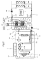
- Fig. 1 is a schematic view of a space-heating and hot water supply apparatus according to a first embodiment of the present invention
- Fig. 1 is a schematic view showing a construction of a space-heating and hot water supply apparatus according to a first embodiment of the invention.
- the space-heating and hot water supply apparatus includes a heat pump unit 1, a hot-water storage tank 2, a hot-water supplying heat exchanger 3, a space-heating circulation circuit 4, a boil-up circulation circuit 5 as an example of a heating circulation circuit, and a defrosting circulation circuit 50.
- the heat pump unit 1 which includes a refrigerant circuit 16 and an electric blower 17, boils up the water in the hot-water storage tank 2 to make hot water.
- the heat pump unit 1 is connected to the hot-water storage tank 2 via the boil-up circulation circuit 5.
- the refrigerant circuit 16 has an evaporator 11, a compressor 12, a condenser 13, a supercooling heat exchanger 14, an expansion valve 15, and a defrosting heat exchanger 19.
- a CO 2 refrigerant circulates.
- the evaporator 11 is an example of the first evaporator
- the expansion valve 15 is an example of the expansion mechanism
- the defrosting heat exchanger 19 is an example of the second evaporator.
- the supercooling heat exchanger 14 is placed downstream of the evaporator 11 and upstream of the defrosting heat exchanger 19. This arrangement makes it possible to lower the temperature of the CO 2 refrigerant directed from the condenser 13 toward the expansion valve 15.
- the defrosting heat exchanger 19 is placed downstream of the supercooling heat exchanger 14 and upstream of the compressor 12.
- the defrosting heat exchanger 19 is connected to the hot-water storage tank 2 via the defrosting circulation circuit 50.
- hot water in the hot-water storage tank 2 can be supplied to the defrosting heat exchanger 19 so that the temperature of the CO 2 refrigerant directed from the supercooling heat exchanger 14 toward the compressor 12 can be raised.
- the CO 2 refrigerant absorbs heat in the air fed from the electric blower 17 so as to be increased in temperature. Then, the CO 2 refrigerant is compressed by the compressor 12 so as to be further increased in temperature, and thereafter enters into the condenser 13 via the defrosting heat exchanger 19, dissipating heat. As a result, the CO 2 refrigerant becomes lower in temperature than that before entering into the condenser 13, and flows toward the supercooling heat exchanger 14. Then, the CO 2 refrigerant is further cooled by the supercooling heat exchanger 14, thereafter passing through the expansion valve 15 to return to the evaporator 11.
- hot water in the hot-water storage tank 2 is supplied to the defrosting heat exchanger 19 via the defrosting circulation circuit 50. Therefore, the CO 2 refrigerant that has entered into the defrosting heat exchanger 19 is heat-exchanged with hot water derived from the hot-water storage tank 2 so as to be further increased in temperature.
- the defrosting heat exchanger 19 is supplied with no hot water from the hot-water storage tank 2, so that the CO 2 refrigerant is not increased in temperature in the defrosting heat exchanger 19.
- a branch valve 55 is provided in this defrosting circulation circuit 50.
- This branch valve 55 has an inlet for inflow of hot water from the hot-water storage tank 2, and two outlets for outflow of hot water. One of the two outlets is connected to the condenser 13, and the other outlet is connected to the defrosting heat exchanger 19.
- a degree of opening of the one outlet By controlling a degree of opening of the one outlet, the quantity of the hot water that enters into the condenser 13 can be controlled.
- the degree of opening of the other outlet the quantity of the hot water that enters into the defrosting heat exchanger 19 can be controlled.
- the degree of opening of each of the outlets of the branch valve 7 is controlled by a control section 7.
- the branch valve 55 is an example of the flow control section.
- boil-up circulation circuit 5 a boil-up circulating pump 51 and a boil-up three-way valve 52 are provided. Then, the boil-up circulation circuit 5 is connected to a second space-heating-forward connection port 42, a boil-up supply port 53, and an antifreezing water turn-back connection port 54.
- a part of the boil-up circulation circuit 5 on the upstream side of the condenser 13 serves also as a part of the defrosting circulation circuit 50 on the upstream side of the defrosting heat exchanger 19. That is, a part between the hot-water storage tank 2 and the branch valve 55 where hot water flows is not only a part of the boil-up circulation circuit 5 but also a part of the defrosting circulation circuit 50.
- the branch valve 55 is provided at a branch portion between the boil-up circulation circuit 5 and the defrosting circulation circuit 50.
- the supply port 53 is provided at a lower portion of the hot-water storage tank 2. As a result of this, hot water in lower region within the hot-water storage tank 2 can be supplied to the boil-up circulating pump 51 via the supply port 53.
- the boil-up circulating pump 51 sucks hot water in the lower part of the hot-water storage tank 2 and discharges the hot water toward the branch valve 55.
- a variable flow rate pump or a constant flow rate circulating pump may be adopted.
- the condenser 13 heat of the CO 2 refrigerant is transferred to the hot water, so that the hot water becomes high temperature (e.g., 60°C - 85°C).
- the high-temperature hot water coming out from the condenser 13 is directed toward the boil-up three-way valve 52.
- the boil-up three-way valve 52 makes a flow of the high-temperature hot water derived from the condenser 13 into an upper part within the hot-water storage tank 2 via the second space-heating-forward connection port 42. Since hot water coming out from the condenser 13 of the heat pump unit 1 has not yet become high temperature enough at start-up of the heat pump unit 1, the boil-up three-way valve 52 makes a flow of the high-temperature hot water derived from the condenser 13 into the lower region within the hot-water storage tank 2 via the antifreezing water turn-back connection port 54. As a result, it can be prevented that hot water that has not become high temperature enough in the condenser 13 turns back to the upper region within the hot-water storage tank 2 to disturb the temperature distribution within the hot-water storage tank 2.
- This hot-water storage tank 2 is for storing hot water heated by the heat pump unit 1.
- a heater 6 is placed generally at a central portion with regard to vertical direction within the hot-water storage tank 2, and the heater 6 directly heats the hot water in the hot-water storage tank 2.
- a plurality of temperature sensors 40A, 40B, ..., 40E are provided on the hot-water storage tank 2 to detect hot-water temperatures of individual portions within the hot-water storage tank 2. These plural temperature sensors 40A, 40B, ..., 40E detect hot-water temperatures of individual portions within the hot-water Storage tank 2 and transmit signals indicative of those temperatures to the control section 7.
- the hot-water supplying heat exchanger 3 formed of a coiled pipe, is placed so as to stretch from lower to upper regions in the hot-water storage tank 2.
- Supply hot water is heated by flowing through within the hot-water supplying heat exchanger 3. More specifically, the supply hot water enters into the hot-water storage tank 2 at a lower portion of the hot-water storage tank 2, then flowing upward through the hot-water supplying heat exchanger 3 placed in the lower region within the hot-water storage tank 2.
- the supply hot water then flows upward through the hot-water supplying heat exchanger 3 placed in the upper region within the hot-water storage tank 2, thereafter going out of the hot-water storage tank 2 from an upper portion of the hot-water storage tank 2.
- a supply-hot-water mixing valve 31 is opened so that the supply hot water having come out of the hot-water storage tank 2 and supply hot water that is before flowing into the hot-water storage tank 2 are mixed together. As a result, the supply hot water coming out of the hot-water storage tank 2 can be decreased in temperature.
- the space-heating circulation circuit 4 is for circulating hot water stored in the hot-water storage tank 2 by making the hot water passed through a plurality of space-heating terminals 8A, 8B, ... outside the hot-water storage tank 2 and thereafter turned back again into the hot-water storage tank 2.
- the space-heating circulation circuit 4 is connected to the first, second space-heating-forward connection ports 41, 42 and a space-heating-backward connection port 43.
- the first space-heating-forward connection port 41 is for taking out hot water in the hot-water storage tank 2.
- the first space-heating-forward connection port 41 is provided generally at a central portion with regard to vertical direction within the hot-water storage tank 2 so as to be located near and above the heater 6. As a result, hot water immediately after being heated by the heater 6 can be taken out from the first space-heating-forward connection port 41 so as to be fed to the plurality of space-heating terminals 8A, 8B, ....
- the second space-heating-forward connection port 42 is also for taking out hot water in the hot-water storage tank 2, like the first space-heating-forward connection port 41.
- the second space-heating-forward connection port 42 is provided at an upper portion of the hot-water storage tank 2.
- hot water in the upper region within the hot-water storage tank 2 can be taken out from the second space-heating-forward connection port 42 so as to be fed to the plurality of space-heating terminals 8A, 8B, ....
- the second space-heating-forward connection port 42 serves also as a boil-up turn-back connection port.
- Each of the space-heating terminals 8A, 8B, ... directly takes out the heat of hot water that has flowed up from the hot-water storage tank 2 and radiates the heat indoors. Then, the hot water lowers in temperature, going out of the space-heating terminals 8A, 8B, ... and flowing toward the space-heating-backward connection port 43.
- the space-heating-backward connection port 43 is provided at a lower portion of the hot-water storage tank 2. As a result, the hot water that has come out from the space-heating-backward connection port 43 can be mixed with the hot water in the lower region within the hot-water storage tank 2.
- a bypass pipe 44 Provided in the space-heating circulation circuit 4 are a bypass pipe 44, a space-heating mixing valve 45, temperature sensors 40F, 40G, a space-heating circulating pump 48, and a space-heating three-way valve 49.
- the bypass pipe 44 guides part of the hot water, which flows from the space-heating terminals 8A, 8B, ... to the space-heating-backward connection port 43, to the space-heating mixing valve 45.
- the space-heating mixing valve 45 has an inlet for inflow of hot water from the hot-water storage tank 2, and an inlet for inflow of hot water from the bypass pipe 44. As will be detailed later, the degree of opening of each of the inlets of the space-heating mixing valve 45 is controlled by the control section 7.
- the control section 7 receives an output signal of an outside air temperature sensor 18, and output signals of the temperature sensors 40A, 40B, ..., 40G.
- the control section 7 also receives a signal indicative of an indoor temperature from an indoor temperature sensor (not shown).
- an output signal of the outside air temperature sensor 18 is a signal indicating a temperature of outside air
- output signals of the temperature sensors 40A, 40B are signals indicating temperatures of hot water in the upper region within the hot-water storage tank 2
- an output signal of the temperature sensor 40C is a signal indicating a temperature of hot water in a intermediate region with regard to vertical direction within the hot-water storage tank 2
- output signals of the temperature sensors 40D, 40E are signals indicating temperatures of hot water in the lower region within the hot-water storage tank 2.
- an output signal of the temperature sensor 40F is a signal indicating a temperature of hot water directed from the hot-water storage tank 2 toward the space-heating terminals 8A, 8B, ....
- An output signal of the temperature sensor 40G is a signal indicating a temperature of hot water directed from the space-heating terminals 8A, 8B, ... toward the hot-water storage tank 2.
- the space-heating circulating pump 48 sucks hot water within the hot-water storage tank 2 via the second space-heating-forward connection port 42 or the first space-heating-forward connection port 41, and discharges the hot water toward the plural space-heating terminals 8A, 8B,
- the space-heating three-way valve 49 takes out hot water from the first space-heating-forward connection port 41 on condition that a high-temperature region of hot water within the hot-water storage tank 2 is present near the first space-heating-forward connection port 41. Also, the space-heating three-way valve 49 takes out hot water from the second space-heating-forward connection port 42 on condition that a high-temperature region of hot water within the hot-water storage tank 2 is absent near the first space-heating-forward connection port 41.
- This switching of the space-heating three-way valve 49 is fulfilled by the control section 7. That is, the control section 7 switches over the space-heating three-way valve 49 based on signals from a plurality of temperature sensors for detecting temperatures of hot water in individual parts within the hot-water storage tank 2.
- the control section 7 turns ON the space-heating circulating pump 48.
- hot water stored in the hot-water storage tank 2 is fed to the plural space-heating terminals 8A, 8B, ..., and returns again to the hot-water storage tank 2.
- the heat of the hot water is radiated indoors via the space-heating terminals 8. That is, the space-heating terminals 8A, 8B, ... directly take out heat of the hot water within the hot-water storage tank 2 to radiate the heat indoors.
- control section 7 controls the compressor 12, the expansion valve 15, the boil-up circulating pump 51 and the branch valve 55 based on signals of the outside air temperature sensor 18, the temperature sensors 40A, 40B, ..., 40E and the indoor temperature sensor.
- the control section 7 boils up the hot water within the hot-water storage tank 2 by the heat pump unit 1. More specifically, the control section 7 turns ON the compressor 12 and the boil-up circulating pump 51 and moreover opens the expansion valve 15. In this case, the control section 7 fully opens the condenser 13-side outlet of the branch valve 55, while the control section 7 fully closes the defrosting heat exchanger 19-side outlet of the branch valve 55.
- the hot water present in the lower region within the hot-water storage tank 2 flows to the condenser 13, and the hot water heated to higher temperature by the condenser 13 is returned into the hot-water storage tank 2 via the second space-heating-forward connection port 42.
- control section 7 starts defrosting operation on condition that the control section 7 decides from an output of the outside air temperature sensor 18 that defrosting operation for removing the frost of the evaporator 11 is needed.
- the control section 7 increases the degree of opening of the expansion valve 15 while opening the defrosting heat exchanger 19-side outlet of the branch valve 55.
- middle-temperature e.g., 30°C - 50°C
- the middle-temperature hot water that has come into the defrosting heat exchanger 19 gives heat to the CO 2 refrigerant directed toward the compressor 12, resulting in low-temperature hot water.
- This low-temperature hot water returns into the hot-water storage tank 2 via the antifreezing water turn-back connection port 54.
- the middle-temperature hot water because of passing through the defrosting heat exchanger 19, decreases in temperature so as to be low-temperature hot water, returning to the lower region within the hot-water storage tank 2. Accordingly, when the hot water within the hot-water storage tank 2 is boiled up after an end of the defrosting operation, the low-temperature hot water in the lower region within the hot-water storage tank 2 is supplied to the heat pump unit 1. As a result of this, the COP of the heat pump unit 1 is improved, thus making it expectable to improve the COP of the heat pump unit 1 for total operation.
- the defrosting heat exchanger 19 is placed on the downstream side of the supercooling heat exchanger 14, the CO 2 refrigerant that has been increased in temperature by the evaporator 11 and the supercooling heat exchanger 14 absorbs heat from the middle-temperature hot water flowing through the defrosting circulation circuit 50. That is, the middle-temperature hot water is cooled by the CO 2 refrigerant.
- the middle-temperature hot water is cooled by the CO 2 refrigerant.
- the CO 2 refrigerant has been increased in temperature by the evaporator 11 and the supercooling heat exchanger 14 so as not to be excessively cold, the middle-temperature hot water can be prevented from being frozen.
- the heat pump unit 1 uses the CO 2 refrigerant, high-temperature hot water can be obtained from the condenser 13.
- a part of the boil-up circulation circuit 5 on the upstream side of the condenser 13 serves also as a part of the defrosting circulation circuit 50 on the upstream side of the defrosting heat exchanger 19. Therefore, if the part of the boil-up circulation circuit 5 on the upstream side of the condenser 13 is constructed, it is not necessary to construct the part of the defrosting circulation circuit 50 on the upstream side of the defrosting heat exchanger 19.
- control section 7 turns ON the boil-up circulating pump 51 and opens the defrosting heat exchanger 19-side outlet of the branch valve 55, allowing a small quantity of hot water to flow to the defrosting circulation circuit 50. This makes it possible to prevent cooling and freezing of hot water remaining within the defrosting circulation circuit 50.
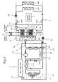
- Fig. 1 is a schematic view showing a construction of a space-heating and hot water supply apparatus according to a second embodiment of the invention.
- Fig. 2 the same component members as those of the first embodiment shown in Fig. 1 are designated by the same reference signs as those of the component members in Fig. 1 , with their description omitted.
- the space-heating and hot water supply apparatus includes a defrosting heat exchanger 219 instead of the supercooling heat exchanger 14 and the defrosting heat exchanger 19 of the first embodiment.
- the defrosting heat exchanger 219 uses hot water within the defrosting circulation circuit 50 to heat the CO 2 refrigerant directed from the evaporator 11 toward the compressor 12 as well as to cool the CO 2 refrigerant directed from the condenser 13 toward the expansion valve 15. That is, the defrosting heat exchanger 219 has functions of both the supercooling heat exchanger 14 and the defrosting heat exchanger 19 of the first embodiment.
- part of the refrigerant circuit 16 between the evaporator 11 and the compressor 12 is brazed to part of the refrigerant circuit 16 between the condenser 13 and the expansion valve 15.
- part of the defrosting circulation circuit 50 is also brazed to part of the refrigerant circuit 16 between the condenser 13 and the expansion valve 15.
- the heat pump unit 1 can be downsized, compared with the first embodiment.
- Fig. 3 is a schematic view showing a construction of a space-heating and hot water supply apparatus according to a third embodiment of the invention.
- the same component members as those of the second embodiment shown in Fig. 2 are designated by the same reference signs as those of the component members in Fig. 2 , with their description omitted.
- the space-heating and hot water supply apparatus includes a temperature sensor 40H as an example of a temperature sensing part.
- This temperature sensor 40H is provided on the defrosting circulation circuit 50 so as to be positioned on downstream side of the defrosting heat exchanger 219.
- the temperature sensor 40H detects a temperature of low-temperature hot water directed from the defrosting heat exchanger 19 toward the hot-water storage tank 2, and outputs a signal indicative of the temperature to the control section 7.
- the control section 7 controls the degree of opening of the defrosting heat exchanger 219-side outlet of the branch valve 55 based on a signal derived from the temperature sensor 40H so that the temperature of low-temperature hot water directed from the defrosting heat exchanger 19 toward the hot-water storage tank 2 is kept from going 0°C or lower as an example.
- Fig. 4 is a schematic view showing a construction of a space-heating and hot water supply apparatus according to a fourth embodiment of the invention.
- the same component members as those of the first embodiment shown in Fig. 1 are designated by the same reference signs as those of the component members in Fig. 1 , with their description omitted.
- the space-heating and hot water supply apparatus includes a defrosting heat exchanger 419 instead of the defrosting heat exchanger 19 of the first embodiment.
- This defrosting heat exchanger 419 has a container 461, and a coiled heat exchanger pipe 462 placed within the container 461.
- the CO 2 refrigerant coming out from the evaporator 11 passes through the supercooling heat exchanger 14 and then enters the container 461. Since the heat exchanger pipe 462 is placed within the container 461, the CO 2 refrigerant comes into contact with the whole surface of the heat exchanger pipe 462.
- the heat pump unit 1 employs CO 2 refrigerant.
- CO 2 refrigerant NH 3 refrigerant, R22 refrigerant and the like may also be used.
- first to fourth embodiments may be combined in their contents as embodiments of the invention.
- space-heating terminals 8A, BB, ... as well as the space-heating circulation circuit 4 and the like associated therewith may be omitted from the first to fourth embodiments to provide a hot water supply apparatus. That is, the present invention may be applied to hot water supply apparatuses dedicated exclusively to supply of hot water without being limited to space-heating and hot water supply apparatuses.
Landscapes
- Engineering & Computer Science (AREA)
- Physics & Mathematics (AREA)
- Mechanical Engineering (AREA)
- Thermal Sciences (AREA)
- General Engineering & Computer Science (AREA)
- Chemical & Material Sciences (AREA)
- Combustion & Propulsion (AREA)
- Heat-Pump Type And Storage Water Heaters (AREA)
Abstract
A heat pump unit 1 has a refrigerant circuit 16, and an evaporator 11, a compressor 12, a condenser 13, an expansion mechanism 15 and a defrosting heat exchanger 19 provided in the refrigerant circuit 16. The defrosting heat exchanger 19 is provided downstream of the evaporator 11 and upstream of the compressor 12. During defrosting operation, hot water within the hot-water storage tank 2 flows through a defrosting circulation circuit 50 to enter into the defrosting heat exchanger 19. A branch valve 55 for controlling flow of hot water flow through the defrosting circulation circuit 50 is provided in the defrosting circulation circuit 50.
Description
- The present invention relates to a hot water system for, for example, hot water supply apparatuses or space-heating and hot water supply apparatuses.
- Conventionally, there has been provided a space-heating and hot water supply apparatus including a heat pump unit placed outdoors, and a hot-water storage tank for storing hot water heated by the heat pump unit.
- In this heat pump unit, which has an evaporator for capturing heat from outside air, frost may be deposited on the evaporator. With frost deposited on the evaporator, the evaporator deteriorates in heat exchange performance, leading to incapability of sufficient space-heating. Therefore, it becomes indispensable to run defrosting operation for removing the frost from the evaporator.
- There has been an issue that water in the hot-water storage tank cannot be boiled up by the heat pump unit during the running of the defrosting operation.
- As a solution for solving this issue, a space-heating and hot water supply apparatus is described in
JP 2004-108597 A - The heat pump unit has a fan, a first evaporator, a second evaporator, a compressor, a condenser, and an expansion valve.
- The first evaporator is located upstream of the compressor and downstream of the second evaporator. The first evaporator receives outside air fed from the fan, and takes in heat from the outside air.
- According to the space-heating and hot water supply apparatus constructed as described above, hot water in the hot-water storage tank is fed to the second evaporator by a pump during the boil-up of the water in the hot-water storage tank by the heat pump unit. As a result of this, a refrigerant that is just before entering the first evaporator is heated by the hot water, so that the frost deposited on the first evaporator can be melted down.
- However, in the space-heating and hot water supply apparatus of
Patent Literature 1 shown above, since the refrigerant heated by the second evaporator enters into the first condenser, the evaporating temperature of the first evaporator increases. - As a result, the quantity of heat taken in from outside air in the first evaporator decreases, causing a problem that COP (Coefficient Of Performance) of the heat pump unit decreases.
- Patent Literature 1:
JP 2004-108597 A - Accordingly, an object of the present invention is to provide a hot water system which allows the defrosting operation to be performed during the boil-up of water in the hot-water storage tank, and yet which allows the heat pump unit to be improved in COP even if such defrosting operation is performed.
- In order to achieve the object, a hot water system according to the present invention comprises:
- a heat pump unit having a refrigerant circuit as well as a first evaporator, a compressor, a condenser and an expansion mechanism provided in the refrigerant circuit;
- a hot-water storage tank for storing hot water;
- a heating circulation circuit for circulating water within the hot-water storage tank by heating and passing the water through the condenser and thereafter returning the water again into the hot-water storage tank;
- a second evaporator provided on the refrigerant circuit;
- a defrosting circulation circuit for circulating hot water stored in the hot-water storage tank by passing the hot water through the second evaporator and thereafter returning the hot water again into the hot-water storage tank; and
- a flow control section which is provided on the defrosting circulation circuit and which controls flow of hot water flowing through the defrosting circulation circuit.
- According to the hot water system of this construction, in performing defrosting operation for removing frost of the first evaporator, hot water within the hot-water storage tank is thrown into flow through the defrosting circulation circuit by control of the flow control section. As a result, the hot water passes through the second evaporator and thereafter returns again into the hot-water storage tank. In this process, the refrigerant that has come into the second evaporator is heated by the hot water, and thereafter flows toward the first evaporator. As a result, the refrigerant entering into the first evaporator increases in temperature, so that frost deposited on the first evaporator can be melted.
- Also, even while the heat pump unit is boiling up hot water within the hot-water storage tank, the hot water within the hot-water storage tank can be put into flow through the defrosting circulation circuit. Thus, defrosting operation can be performed while the hot water within the hot-water storage tank is being boiled up.
- Also, in the case where the defrosting operation is performed by supplying hot water within the hot-water storage tank to the second evaporator, the hot water is lowered in temperature by the second evaporator and thereafter returns to the hot-water storage tank. As a result, when the hot water within the hot-water storage tank is boiled up after an end of the defrosting operation, low-temperature hot water obtained by the defrosting operation can be supplied to the heat pump unit.
- Therefore, the COP of the heat pump unit is improved in the boil-up operation after the defrosting operation, so that improvement in the COP of the heat pump unit for total operation can be expected.
- The hot water system of one embodiment further comprises:
- a hot-water supplying heat exchanger which is placed within the hot-water storage tank and in which supply hot water flows inside; and
- a space-heating circulation circuit for circulating hot water stored in the hot-water storage tank by passing space-heating terminals outside the hot-water storage tank and thereafter returning the hot water again into the hot-water storage tank.
- According to the hot water system of this embodiment, when space-heating operation is started, hot water stored in the hot-water storage tank flows through the space-heating circulation circuit to space-heating terminals and returns again to the hot-water storage tank. As a result, heat of the hot water is radiated indoors via the space-heating terminals. That is, the space-heating terminals directly take out heat within the hot-water storage tank and radiate indoors.
- Therefore, since the heat of hot water within the hot-water storage tank can be efficiently supplied to the space-heating terminals, enough space-heating can be fulfilled even in regions of high space-heating loads, for example, in Nordic countries.
- Conventionally, it would be the case that heat is taken out via heat exchangers within the hot-water storage tank and supplied to space-heating terminals, thus resulting in worse efficiency and incapability of enough space-heating.
- In the hot water system of one embodiment, the second evaporator is placed downstream of the first evaporator and upstream of the compressor.
- According to the hot water system of this embodiment, the second evaporator is placed downstream of the first evaporator and upstream of the compressor. Therefore, the refrigerant increased in temperature by the first evaporator is heat-exchanged with hot water supplied from the hot-water storage tank to the second evaporator.
- Thus, hot water supplied from the hot-water storage tank to the second evaporator can be prevented from freezing due to heat exchange with excessively cold refrigerant.
- The hot water system of one embodiment further comprises a supercooling heat exchanger placed downstream of the first evaporator and upstream of the second evaporator.
- According to the hot water system of this embodiment, a supercooling heat exchanger is placed downstream of the first evaporator and upstream of the second evaporator. Therefore, the refrigerant increased in temperature by the first evaporator is further increased in temperature by the supercooling heat exchanger. Then, the refrigerant further increased in temperature by the supercooling heat exchanger enters into the second evaporator, heat exchanging with hot water supplied from the hot-water storage tank to the second evaporator.
- Thus, the hot water supplied from the hot-water storage tank to the second evaporator is less likely to freeze than in the case where no supercooling heat exchanger is placed downstream of the first evaporator and upstream of the second evaporator.
- In the hot water system of one embodiment, the second evaporator serve also as a supercooling heat exchanger.
- According to the hot water system of this embodiment, the second evaporator serve also as a supercooling heat exchanger. Therefore, a supercooling heat exchanger does not need to be provided in addition to the second evaporator, so that the heat pump unit can be downsized.
- In the hot water system of one embodiment, the second evaporator has
- a container through which a refrigerant flowing through the refrigerant circuit passes; and
- a heat exchanger pipe which is placed within the container and through which hot water derived from the hot-water storage tank flows inside.
- According to the hot water system of this embodiment, the heat exchanger pipe is placed within the container. Therefore, the refrigerant that has come into the container is put into contact with the whole surface of the heat exchanger pipe.
- Thus, heat of the hot water derived from the hot-water storage tank is efficiently transferred to the refrigerant within the container via the heat exchanger pipe.
- In the hot water system of one embodiment, the refrigerant flowing through the refrigerant circuit is a CO2 refrigerant.
- According to the hot water system of this embodiment, since the refrigerant flowing through the refrigerant circuit is a CO2 refrigerant, the heat pump unit is enabled to output high-temperature hot water.
- In the hot water system of one embodiment,
- a part of the heating circulation circuit on an upstream side of the condenser serves also as a part of the defrosting circulation circuit on an upstream side of the second evaporator,
- the flow control section is provided at a branch portion between the heating circulation circuit and the defrosting circulation circuit to control a flow rate of hot water flowing from a part of the heating circulation circuit on the upstream side of the condenser to the condenser and a flow rate of hot water flowing from a part of the heating circulation circuit on the upstream side of the condenser to the second evaporator.
- According to the hot water system of this embodiment, a part of the heating circulation circuit on an upstream side of the condenser serves also as a part of the defrosting circulation circuit on an upstream side of the second evaporator. Therefore, if the part of the heating circulation circuit on the upstream side of the condenser is constructed, it is not necessary to construct the part of the defrosting circulation circuit on the upstream side of the second evaporator.
- Thus, time and labor associated with construction of the heating circulation circuit and the defrosting circulation circuit are reduced, so that constructional workability of the heating circulation circuit and the defrosting circulation circuit can be improved.
- Also, the flow control section is provided at a branch portion between the heating circulation circuit and the defrosting circulation circuit. Therefore, the flow of hot water through the heating circulation circuit and the flow of hot water through the defrosting circulation circuit can be controlled by one flow control section.
- Thus, flow control for the flow of hot water through the heating circulation circuit and for the flow of hot water through the defrosting circulation circuit can be prevented from being complicated.
- Besides, during non-defrosting operation, by giving a flow of a necessary minimum quantity of hot water through the second evaporator by the flow control section, it becomes possible to prevent cooling and freezing of hot water within the defrosting circulation circuit.
- The hot water system of one embodiment further comprises a control section for controlling the flow control section so that a quantity of hot water flowing into the second evaporator during defrosting operation of the first evaporator becomes larger than a quantity of hot water flowing into the second evaporator during non-defrosting operation of the first evaporator.
- According to the hot water system of this embodiment, the control section controls the flow control section so that a quantity of hot water flowing into the second evaporator during defrosting operation of the first evaporator becomes larger than a quantity of hot water flowing into the second evaporator during non-defrosting operation of the first evaporator. As a result, the temperature of the refrigerant that has come into the second evaporator can reliably be increased up to a temperature that allows the defrosting of the first evaporator to be achieved.
- The hot water system of one embodiment further comprises
- a temperature sensing part for sensing a temperature of hot water that has come out from the second evaporator, wherein
- the control section controls the flow control section based on an output of the temperature sensing part.
- According to the hot water system of this embodiment, the temperature sensing part senses a temperature of hot water that has come out from the second evaporator and directed toward the hot-water storage tank. In this case, the control section controls the flow control section based on an output of the temperature sensing part so that the temperature of hot water coming out from the second evaporator and directed toward the hot-water storage tank is kept from becoming, for example, 0°C or lower. This makes it possible to reliably prevent cooling and freezing of hot water within the defrosting circulation circuit.
- According to the hot water system of the present invention, in performing defrosting operation for removing frost of the first evaporator in the heat pump unit, hot water within the hot-water storage tank is thrown into flow through the defrosting circulation circuit so as to enter into the second evaporator, by control of the flow control section. As a result, the refrigerant coming into the second evaporator is heated by the hot water, increasing in temperature.
- Thus, the refrigerant entering into the second evaporator, after coming out from the second evaporator, flows through the refrigerant circuit and returns to the first evaporator, so that the frost deposited on the first evaporator can be melted.
- Also, even while the heat pump unit is boiling up hot water within the hot-water storage tank, the hot water within the hot-water storage tank can be put into flow through the defrosting circulation circuit. Thus, defrosting operation can be performed while the hot water within the hot-water storage tank is being boiled up.
- Also, in the case where the defrosting operation is performed by supplying hot water within the hot-water storage tank to the second evaporator, the hot water is lowered in temperature by the second evaporator and thereafter returns to the hot-water storage tank. As a result, when the hot water within the hot-water storage tank is boiled up after an end of the defrosting operation, low-temperature hot water obtained by the defrosting operation can be supplied to the heat pump unit.
- Therefore, the COP of the heat pump unit is improved in the boil-up operation after the defrosting operation, so that the COP of the heat pump unit for total operation can be improved.
-
Fig. 1 is a schematic view of a space-heating and hot water supply apparatus according to a first embodiment of the present invention; -
Fig. 2 is a schematic view of a space-heating and hot water supply apparatus according to a second embodiment of the invention; -
Fig. 3 is a schematic view of a space-heating and hot water supply apparatus according to a third embodiment of the invention; and -
Fig. 4 is a schematic view of a space-heating and hot water supply apparatus according to a fourth embodiment of the invention. - Hereinbelow, the hot water system of the present invention will be described in detail by embodiments thereof illustrated in the accompanying drawings.
-
Fig. 1 is a schematic view showing a construction of a space-heating and hot water supply apparatus according to a first embodiment of the invention. - The space-heating and hot water supply apparatus includes a
heat pump unit 1, a hot-water storage tank 2, a hot-water supplyingheat exchanger 3, a space-heating circulation circuit 4, a boil-upcirculation circuit 5 as an example of a heating circulation circuit, and adefrosting circulation circuit 50. - First, the
heat pump unit 1 is described below. Theheat pump unit 1, which includes arefrigerant circuit 16 and anelectric blower 17, boils up the water in the hot-water storage tank 2 to make hot water. Theheat pump unit 1 is connected to the hot-water storage tank 2 via the boil-upcirculation circuit 5. - The
refrigerant circuit 16 has an evaporator 11, acompressor 12, acondenser 13, asupercooling heat exchanger 14, anexpansion valve 15, and adefrosting heat exchanger 19. In thisrefrigerant circuit 16, a CO2 refrigerant circulates. In addition, the evaporator 11 is an example of the first evaporator, theexpansion valve 15 is an example of the expansion mechanism, and thedefrosting heat exchanger 19 is an example of the second evaporator. - The supercooling
heat exchanger 14 is placed downstream of the evaporator 11 and upstream of thedefrosting heat exchanger 19. This arrangement makes it possible to lower the temperature of the CO2 refrigerant directed from thecondenser 13 toward theexpansion valve 15. - The
defrosting heat exchanger 19 is placed downstream of thesupercooling heat exchanger 14 and upstream of thecompressor 12. Thedefrosting heat exchanger 19 is connected to the hot-water storage tank 2 via thedefrosting circulation circuit 50. As a result, hot water in the hot-water storage tank 2 can be supplied to thedefrosting heat exchanger 19 so that the temperature of the CO2 refrigerant directed from the supercoolingheat exchanger 14 toward thecompressor 12 can be raised. - In the evaporator 11, the CO2 refrigerant absorbs heat in the air fed from the
electric blower 17 so as to be increased in temperature. Then, the CO2 refrigerant is compressed by thecompressor 12 so as to be further increased in temperature, and thereafter enters into thecondenser 13 via thedefrosting heat exchanger 19, dissipating heat. As a result, the CO2 refrigerant becomes lower in temperature than that before entering into thecondenser 13, and flows toward the supercoolingheat exchanger 14. Then, the CO2 refrigerant is further cooled by the supercoolingheat exchanger 14, thereafter passing through theexpansion valve 15 to return to the evaporator 11. - During defrosting operation for removing the frost of the evaporator 11, hot water in the hot-
water storage tank 2 is supplied to thedefrosting heat exchanger 19 via thedefrosting circulation circuit 50. Therefore, the CO2 refrigerant that has entered into thedefrosting heat exchanger 19 is heat-exchanged with hot water derived from the hot-water storage tank 2 so as to be further increased in temperature. - During non-defrosting operation, on the other hand, the
defrosting heat exchanger 19 is supplied with no hot water from the hot-water storage tank 2, so that the CO2 refrigerant is not increased in temperature in thedefrosting heat exchanger 19. - Next described is the
defrosting circulation circuit 50. In thisdefrosting circulation circuit 50, abranch valve 55 is provided. Thisbranch valve 55 has an inlet for inflow of hot water from the hot-water storage tank 2, and two outlets for outflow of hot water. One of the two outlets is connected to thecondenser 13, and the other outlet is connected to thedefrosting heat exchanger 19. By controlling a degree of opening of the one outlet, the quantity of the hot water that enters into thecondenser 13 can be controlled. Also, by controlling the degree of opening of the other outlet, the quantity of the hot water that enters into thedefrosting heat exchanger 19 can be controlled. The degree of opening of each of the outlets of thebranch valve 7 is controlled by acontrol section 7. In addition, thebranch valve 55 is an example of the flow control section. - Next described is the boil-up
circulation circuit 5. In this boil-upcirculation circuit 5, a boil-up circulatingpump 51 and a boil-up three-way valve 52 are provided. Then, the boil-upcirculation circuit 5 is connected to a second space-heating-forward connection port 42, a boil-upsupply port 53, and an antifreezing water turn-back connection port 54. - To the antifreezing water turn-
back connection port 54, hot water flows up from thecondenser 13 or hot water flows up from thedefrosting heat exchanger 19. - A part of the boil-up
circulation circuit 5 on the upstream side of thecondenser 13 serves also as a part of thedefrosting circulation circuit 50 on the upstream side of thedefrosting heat exchanger 19. That is, a part between the hot-water storage tank 2 and thebranch valve 55 where hot water flows is not only a part of the boil-upcirculation circuit 5 but also a part of thedefrosting circulation circuit 50. Thebranch valve 55 is provided at a branch portion between the boil-upcirculation circuit 5 and thedefrosting circulation circuit 50. - The
supply port 53 is provided at a lower portion of the hot-water storage tank 2. As a result of this, hot water in lower region within the hot-water storage tank 2 can be supplied to the boil-up circulatingpump 51 via thesupply port 53. - The boil-up circulating
pump 51 sucks hot water in the lower part of the hot-water storage tank 2 and discharges the hot water toward thebranch valve 55. As the boil-up circulatingpump 51, a variable flow rate pump or a constant flow rate circulating pump may be adopted. - In the
condenser 13, heat of the CO2 refrigerant is transferred to the hot water, so that the hot water becomes high temperature (e.g., 60°C - 85°C). The high-temperature hot water coming out from thecondenser 13 is directed toward the boil-up three-way valve 52. - During hot water supply operation and space-heating operation, the boil-up three-
way valve 52 makes a flow of the high-temperature hot water derived from thecondenser 13 into an upper part within the hot-water storage tank 2 via the second space-heating-forward connection port 42. Since hot water coming out from thecondenser 13 of theheat pump unit 1 has not yet become high temperature enough at start-up of theheat pump unit 1, the boil-up three-way valve 52 makes a flow of the high-temperature hot water derived from thecondenser 13 into the lower region within the hot-water storage tank 2 via the antifreezing water turn-back connection port 54. As a result, it can be prevented that hot water that has not become high temperature enough in thecondenser 13 turns back to the upper region within the hot-water storage tank 2 to disturb the temperature distribution within the hot-water storage tank 2. - Next, the hot-
water storage tank 2 is described. This hot-water storage tank 2 is for storing hot water heated by theheat pump unit 1. Aheater 6 is placed generally at a central portion with regard to vertical direction within the hot-water storage tank 2, and theheater 6 directly heats the hot water in the hot-water storage tank 2. Also, a plurality oftemperature sensors water storage tank 2 to detect hot-water temperatures of individual portions within the hot-water storage tank 2. Theseplural temperature sensors water Storage tank 2 and transmit signals indicative of those temperatures to thecontrol section 7. - Next, the hot-water supplying
heat exchanger 3 is described. The hot-water supplyingheat exchanger 3, formed of a coiled pipe, is placed so as to stretch from lower to upper regions in the hot-water storage tank 2. Supply hot water is heated by flowing through within the hot-water supplyingheat exchanger 3. More specifically, the supply hot water enters into the hot-water storage tank 2 at a lower portion of the hot-water storage tank 2, then flowing upward through the hot-water supplyingheat exchanger 3 placed in the lower region within the hot-water storage tank 2. The supply hot water then flows upward through the hot-water supplyingheat exchanger 3 placed in the upper region within the hot-water storage tank 2, thereafter going out of the hot-water storage tank 2 from an upper portion of the hot-water storage tank 2. - When the supply hot water that has come out of the hot-
water storage tank 2 is too high in temperature, a supply-hot-water mixing valve 31 is opened so that the supply hot water having come out of the hot-water storage tank 2 and supply hot water that is before flowing into the hot-water storage tank 2 are mixed together. As a result, the supply hot water coming out of the hot-water storage tank 2 can be decreased in temperature. - Next, the space-
heating circulation circuit 4 is described. The space-heating circulation circuit 4 is for circulating hot water stored in the hot-water storage tank 2 by making the hot water passed through a plurality of space-heating terminals water storage tank 2 and thereafter turned back again into the hot-water storage tank 2. The space-heating circulation circuit 4 is connected to the first, second space-heating-forward connection ports backward connection port 43. - The first space-heating-
forward connection port 41 is for taking out hot water in the hot-water storage tank 2. The first space-heating-forward connection port 41 is provided generally at a central portion with regard to vertical direction within the hot-water storage tank 2 so as to be located near and above theheater 6. As a result, hot water immediately after being heated by theheater 6 can be taken out from the first space-heating-forward connection port 41 so as to be fed to the plurality of space-heating terminals - The second space-heating-
forward connection port 42 is also for taking out hot water in the hot-water storage tank 2, like the first space-heating-forward connection port 41. The second space-heating-forward connection port 42 is provided at an upper portion of the hot-water storage tank 2. As a result, hot water in the upper region within the hot-water storage tank 2 can be taken out from the second space-heating-forward connection port 42 so as to be fed to the plurality of space-heating terminals forward connection port 42 serves also as a boil-up turn-back connection port. - Each of the space-
heating terminals water storage tank 2 and radiates the heat indoors. Then, the hot water lowers in temperature, going out of the space-heating terminals backward connection port 43. - The space-heating-
backward connection port 43 is provided at a lower portion of the hot-water storage tank 2. As a result, the hot water that has come out from the space-heating-backward connection port 43 can be mixed with the hot water in the lower region within the hot-water storage tank 2. - Provided in the space-
heating circulation circuit 4 are abypass pipe 44, a space-heating mixing valve 45,temperature sensors heating circulating pump 48, and a space-heating three-way valve 49. - The
bypass pipe 44 guides part of the hot water, which flows from the space-heating terminals backward connection port 43, to the space-heating mixing valve 45. - The space-
heating mixing valve 45 has an inlet for inflow of hot water from the hot-water storage tank 2, and an inlet for inflow of hot water from thebypass pipe 44. As will be detailed later, the degree of opening of each of the inlets of the space-heating mixing valve 45 is controlled by thecontrol section 7. - The
control section 7 receives an output signal of an outsideair temperature sensor 18, and output signals of thetemperature sensors control section 7 also receives a signal indicative of an indoor temperature from an indoor temperature sensor (not shown). It is noted here that an output signal of the outsideair temperature sensor 18 is a signal indicating a temperature of outside air, output signals of thetemperature sensors water storage tank 2, an output signal of thetemperature sensor 40C is a signal indicating a temperature of hot water in a intermediate region with regard to vertical direction within the hot-water storage tank 2, and output signals of thetemperature sensors water storage tank 2. Also, an output signal of thetemperature sensor 40F is a signal indicating a temperature of hot water directed from the hot-water storage tank 2 toward the space-heating terminals temperature sensor 40G is a signal indicating a temperature of hot water directed from the space-heating terminals water storage tank 2. - The space-
heating circulating pump 48 sucks hot water within the hot-water storage tank 2 via the second space-heating-forward connection port 42 or the first space-heating-forward connection port 41, and discharges the hot water toward the plural space-heating terminals - The space-heating three-
way valve 49 takes out hot water from the first space-heating-forward connection port 41 on condition that a high-temperature region of hot water within the hot-water storage tank 2 is present near the first space-heating-forward connection port 41. Also, the space-heating three-way valve 49 takes out hot water from the second space-heating-forward connection port 42 on condition that a high-temperature region of hot water within the hot-water storage tank 2 is absent near the first space-heating-forward connection port 41. This switching of the space-heating three-way valve 49 is fulfilled by thecontrol section 7. That is, thecontrol section 7 switches over the space-heating three-way valve 49 based on signals from a plurality of temperature sensors for detecting temperatures of hot water in individual parts within the hot-water storage tank 2. - According to the space-heating and hot water supply apparatus constructed as described above, as the space-heating operation starts, the
control section 7 turns ON the space-heating circulating pump 48. As a result of this, hot water stored in the hot-water storage tank 2 is fed to the plural space-heating terminals water storage tank 2. During this process, the heat of the hot water is radiated indoors via the space-heating terminals 8. That is, the space-heating terminals water storage tank 2 to radiate the heat indoors. - Therefore, since the heat of hot water within the hot-
water storage tank 2 can be efficiently supplied to the space-heating terminals - During the space-heating operation, the
control section 7 controls thecompressor 12, theexpansion valve 15, the boil-up circulatingpump 51 and thebranch valve 55 based on signals of the outsideair temperature sensor 18, thetemperature sensors - For instance, when deciding from the output signals of the
temperature sensors water storage tank 2 has become small in quantity, thecontrol section 7 boils up the hot water within the hot-water storage tank 2 by theheat pump unit 1. More specifically, thecontrol section 7 turns ON thecompressor 12 and the boil-up circulatingpump 51 and moreover opens theexpansion valve 15. In this case, thecontrol section 7 fully opens the condenser 13-side outlet of thebranch valve 55, while thecontrol section 7 fully closes the defrosting heat exchanger 19-side outlet of thebranch valve 55. As a result, the hot water present in the lower region within the hot-water storage tank 2 flows to thecondenser 13, and the hot water heated to higher temperature by thecondenser 13 is returned into the hot-water storage tank 2 via the second space-heating-forward connection port 42. - Then, while the hot water within the hot-
water storage tank 2 is boiled up by theheat pump unit 1, thecontrol section 7 starts defrosting operation on condition that thecontrol section 7 decides from an output of the outsideair temperature sensor 18 that defrosting operation for removing the frost of the evaporator 11 is needed. - Upon start of the defrosting operation, the
control section 7 increases the degree of opening of theexpansion valve 15 while opening the defrosting heat exchanger 19-side outlet of thebranch valve 55. As a result, middle-temperature (e.g., 30°C - 50°C) hot water in the lower region within the hot-water storage tank 2 flows to both thecondenser 13 and thedefrosting heat exchanger 19. The middle-temperature hot water that has come into thedefrosting heat exchanger 19 gives heat to the CO2 refrigerant directed toward thecompressor 12, resulting in low-temperature hot water. This low-temperature hot water returns into the hot-water storage tank 2 via the antifreezing water turn-back connection port 54. - In this way, as the middle-temperature hot water passes through the
defrosting heat exchanger 19 and then returns again into the hot-water storage tank 2, the CO2 refrigerant coming into the evaporator 11 becomes appropriately high temperature. As a result of this, frost can be removed from the evaporator 11. - During the defrosting operation, heat is not taken in from the outside air, but heat is taken in from the middle-temperature hot water in the lower region within the hot-
water storage tank 2. This heat is heat of hot water boiled up by theheat pump unit 1 before the defrosting operation. Therefore, the COP of theheat pump unit 1 becomes worse as far as the defrosting operation is concerned. However, this is also the case even in conventional defrosting operation, in which the middle-temperature hot water in the lower region within the hot-water storage tank 2 is not used. - However, in the case of defrosting operation in which middle-temperature hot water in the lower region within the hot-
water storage tank 2 is used, the middle-temperature hot water, because of passing through thedefrosting heat exchanger 19, decreases in temperature so as to be low-temperature hot water, returning to the lower region within the hot-water storage tank 2. Accordingly, when the hot water within the hot-water storage tank 2 is boiled up after an end of the defrosting operation, the low-temperature hot water in the lower region within the hot-water storage tank 2 is supplied to theheat pump unit 1. As a result of this, the COP of theheat pump unit 1 is improved, thus making it expectable to improve the COP of theheat pump unit 1 for total operation. - Also, since the
defrosting heat exchanger 19 is placed on the downstream side of thesupercooling heat exchanger 14, the CO2 refrigerant that has been increased in temperature by the evaporator 11 and thesupercooling heat exchanger 14 absorbs heat from the middle-temperature hot water flowing through thedefrosting circulation circuit 50. That is, the middle-temperature hot water is cooled by the CO2 refrigerant. - As shown above, the middle-temperature hot water is cooled by the CO2 refrigerant. However, because the CO2 refrigerant has been increased in temperature by the evaporator 11 and the
supercooling heat exchanger 14 so as not to be excessively cold, the middle-temperature hot water can be prevented from being frozen. - If the
defrosting heat exchanger 19 is placed between the evaporator 11 and theexpansion valve 15, excessively cold CO2 refrigerant directed from theexpansion valve 15 toward the evaporator 11 cools the middle-temperature hot water flowing through thedefrosting circulation circuit 50, so that the middle-temperature hot water may be frozen, making it impossible to continue the defrosting operation. - Further, since the
heat pump unit 1 uses the CO2 refrigerant, high-temperature hot water can be obtained from thecondenser 13. - Also, a part of the boil-up
circulation circuit 5 on the upstream side of thecondenser 13 serves also as a part of thedefrosting circulation circuit 50 on the upstream side of thedefrosting heat exchanger 19. Therefore, if the part of the boil-upcirculation circuit 5 on the upstream side of thecondenser 13 is constructed, it is not necessary to construct the part of thedefrosting circulation circuit 50 on the upstream side of thedefrosting heat exchanger 19. - Therefore, time and labor associated with construction of the boil-up
circulation circuit 5 and thedefrosting circulation circuit 50 are reduced, so that constructional workability of the boil-upcirculation circuit 5 and thedefrosting circulation circuit 50 is successful. - Further, the flow of hot water through the boil-up
circulation circuit 5 as well as the flow of hot water through thedefrosting circulation circuit 50 are controlled by onebranch valve 55 alone. Thus, flow control for those members can be prevented from being complicated. - Further, during non-defrosting operation in which space-heating operation is not performed, the
control section 7 turns ON the boil-up circulatingpump 51 and opens the defrosting heat exchanger 19-side outlet of thebranch valve 55, allowing a small quantity of hot water to flow to thedefrosting circulation circuit 50. This makes it possible to prevent cooling and freezing of hot water remaining within thedefrosting circulation circuit 50. -
Fig. 1 is a schematic view showing a construction of a space-heating and hot water supply apparatus according to a second embodiment of the invention. InFig. 2 , the same component members as those of the first embodiment shown inFig. 1 are designated by the same reference signs as those of the component members inFig. 1 , with their description omitted. - The space-heating and hot water supply apparatus includes a
defrosting heat exchanger 219 instead of thesupercooling heat exchanger 14 and thedefrosting heat exchanger 19 of the first embodiment. - The
defrosting heat exchanger 219 uses hot water within thedefrosting circulation circuit 50 to heat the CO2 refrigerant directed from the evaporator 11 toward thecompressor 12 as well as to cool the CO2 refrigerant directed from thecondenser 13 toward theexpansion valve 15. That is, thedefrosting heat exchanger 219 has functions of both thesupercooling heat exchanger 14 and thedefrosting heat exchanger 19 of the first embodiment. - More specifically, in the
defrosting heat exchanger 219, part of therefrigerant circuit 16 between the evaporator 11 and thecompressor 12 is brazed to part of therefrigerant circuit 16 between thecondenser 13 and theexpansion valve 15. In addition, part of thedefrosting circulation circuit 50 is also brazed to part of therefrigerant circuit 16 between thecondenser 13 and theexpansion valve 15. - According to the space-heating and hot water supply apparatus having the above construction, only the
defrosting heat exchanger 219 is placed between the evaporator 11 and thecompressor 12. Therefore, theheat pump unit 1 can be downsized, compared with the first embodiment. -
Fig. 3 is a schematic view showing a construction of a space-heating and hot water supply apparatus according to a third embodiment of the invention. InFig. 3 , the same component members as those of the second embodiment shown inFig. 2 are designated by the same reference signs as those of the component members inFig. 2 , with their description omitted. - The space-heating and hot water supply apparatus includes a
temperature sensor 40H as an example of a temperature sensing part. Thistemperature sensor 40H is provided on thedefrosting circulation circuit 50 so as to be positioned on downstream side of thedefrosting heat exchanger 219. Thetemperature sensor 40H detects a temperature of low-temperature hot water directed from thedefrosting heat exchanger 19 toward the hot-water storage tank 2, and outputs a signal indicative of the temperature to thecontrol section 7. - According to the space-heating and hot water supply apparatus having the above construction, when hot water flows within the
defrosting circulation circuit 50, thecontrol section 7 controls the degree of opening of the defrosting heat exchanger 219-side outlet of thebranch valve 55 based on a signal derived from thetemperature sensor 40H so that the temperature of low-temperature hot water directed from thedefrosting heat exchanger 19 toward the hot-water storage tank 2 is kept from going 0°C or lower as an example. - As a result, there can be prevented an occurrence that hot water frozen within the
defrosting circulation circuit 50 causes the defrosting operation to be no longer implementable. -
Fig. 4 is a schematic view showing a construction of a space-heating and hot water supply apparatus according to a fourth embodiment of the invention. InFig. 4 , the same component members as those of the first embodiment shown inFig. 1 are designated by the same reference signs as those of the component members inFig. 1 , with their description omitted. - The space-heating and hot water supply apparatus includes a
defrosting heat exchanger 419 instead of thedefrosting heat exchanger 19 of the first embodiment. Thisdefrosting heat exchanger 419 has acontainer 461, and a coiledheat exchanger pipe 462 placed within thecontainer 461. - According to the space-heating and hot water supply apparatus having the above construction, the CO2 refrigerant coming out from the evaporator 11 passes through the supercooling
heat exchanger 14 and then enters thecontainer 461. Since theheat exchanger pipe 462 is placed within thecontainer 461, the CO2 refrigerant comes into contact with the whole surface of theheat exchanger pipe 462. - Therefore, heat of the middle-temperature hot water derived from the hot-
water storage tank 2 is efficiently transferred to the CO2 refrigerant within thecontainer 461 via theheat exchanger pipe 462. - In the first to fourth embodiments, the
heat pump unit 1 employs CO2 refrigerant. However, NH3 refrigerant, R22 refrigerant and the like may also be used. - Further, the first to fourth embodiments may be combined in their contents as embodiments of the invention.
- Further, the space-
heating terminals 8A, BB, ... as well as the space-heating circulation circuit 4 and the like associated therewith may be omitted from the first to fourth embodiments to provide a hot water supply apparatus. That is, the present invention may be applied to hot water supply apparatuses dedicated exclusively to supply of hot water without being limited to space-heating and hot water supply apparatuses. -
- 1
- heat pump unit
- 2
- hot-water storage tank
- 3
- hot-water supplying heat exchanger
- 5
- boil-up circulation circuit
- 8A, 8B, ...
- space-heating terminal
- 11
- evaporator
- 12
- compressor
- 13
- condenser
- 14
- supercooling heat exchanger
- 15
- expansion valve
- 16
- refrigerant circuit
- 19, 219, 419
- defrosting heat exchanger
- 40H
- temperature sensor
- 50
- defrosting circulation circuit
- 55
- branch valve
- 461
- container
- 462
- heat exchanger pipe
Claims (10)
- A hot water system comprising:a heat pump unit (1) having a refrigerant circuit (16) as well as a first evaporator (11), a compressor (12), a condenser (13) and an expansion mechanism (15) provided in the refrigerant circuit (16);a hot-water storage tank (2) for storing hot water;a heating circulation circuit (5) for circulating water within the hot-water storage tank (2) by heating and passing the water through the condenser (13) and thereafter returning the water again into the hot-water storage tank (2);a second evaporator (19, 219, 419) provided on the refrigerant circuit (16);a defrosting circulation circuit (50) for circulating hot water stored in the hot-water storage tank (2) by passing the hot water through the second evaporator (19, 219, 419) and thereafter returning the hot water again into the hot-water storage tank (2); anda flow control section (55) which is provided on the defrosting circulation circuit (50) and which controls flow of hot water flowing through the defrosting circulation circuit (50).
- The hot water system as claimed in Claim 1, further comprising:a hot-water supplying heat exchanger (3) which is placed within the hot-water storage tank (2) and in which supply hot water flows inside; anda space-heating circulation circuit (4) for circulating hot water stored in the hot-water storage tank by passing space-heating terminals outside the hot-water storage tank and thereafter returning the hot water again into the hot-water storage tank.
- The hot water system as claimed in Claim 1 or 2, wherein
the second evaporator (19, 219, 419) is placed downstream of the first evaporator (11) and upstream of the compressor (12). - The hot water system as claimed in Claim 1 or 2, further comprising
a supercooling heat exchanger (14) placed downstream of the first evaporator (11) and upstream of the second evaporator (19, 419). - The hot water system as claimed in Claim 1 or 2, wherein
the second evaporator (219) serve also as a supercooling heat exchanger. - The hot water system as claimed in Claim 1 or 2, wherein
the second evaporator (419) has
a container (461) through which a refrigerant flowing through the refrigerant circuit (16) passes; and
a heat exchanger pipe (462) which is placed within the container (461) and through which hot water derived from the hot-water storage tank (2) flows inside. - The hot water system as claimed in Claim 1 or 2, wherein
the refrigerant flowing through the refrigerant circuit (16) is a CO2 refrigerant. - The hot water system as claimed in Claim 1 or 2, wherein
a part of the heating circulation circuit (5) on an upstream side of the condenser (13) serves also as a part of the defrosting circulation circuit (50) on an upstream side of the second evaporator (19, 219, 419),
the flow control section (55) is provided at a branch portion between the heating circulation circuit (5) and the defrosting circulation circuit (50) to control a flow rate of hot water flowing from a part of the heating circulation circuit (5) on the upstream side of the condenser (13) to the condenser (13) and a flow rate of hot water flowing from a part of the heating circulation circuit (5) on the upstream side of the condenser (13) to the second evaporator (19, 219, 419). - The hot water system as claimed in Claim 8, further comprising
a control section (7) for controlling the flow control section (55) so that a quantity of hot water flowing into the second evaporator (19, 219, 419) during defrosting operation of the first evaporator (11) becomes larger than a quantity of hot water flowing into the second evaporator (19, 219, 419) during non-defrosting operation of the first evaporator (11). - The hot water system as claimed in Claim 9, further comprising
a temperature sensing part (40H) for sensing a temperature of hot water that has come out from the second evaporator (19, 219, 419), wherein
the control section (7) controls the flow control section (55) based on an output of the temperature sensing part (40H).
Applications Claiming Priority (3)
| Application Number | Priority Date | Filing Date | Title |
|---|---|---|---|
| JP2008149139A JP4479833B2 (en) | 2008-06-06 | 2008-06-06 | Hot water system |
| JP2008181385A JP4479836B2 (en) | 2008-07-11 | 2008-07-11 | Hot water system |
| PCT/JP2009/059960 WO2009148011A1 (en) | 2008-06-06 | 2009-06-01 | Hot water system |
Publications (1)
| Publication Number | Publication Date |
|---|---|
| EP2306111A1 true EP2306111A1 (en) | 2011-04-06 |
Family
ID=41398089
Family Applications (1)
| Application Number | Title | Priority Date | Filing Date |
|---|---|---|---|
| EP09758278A Withdrawn EP2306111A1 (en) | 2008-06-06 | 2009-06-01 | Hot water system |
Country Status (2)
| Country | Link |
|---|---|
| EP (1) | EP2306111A1 (en) |
| WO (1) | WO2009148011A1 (en) |
Cited By (13)
| Publication number | Priority date | Publication date | Assignee | Title |
|---|---|---|---|---|
| WO2014072743A1 (en) * | 2012-11-09 | 2014-05-15 | BASILE, Martino | Heating system |
| EP2333457A3 (en) * | 2009-12-11 | 2015-06-24 | LG ELectronics INC. | Water circulation apparatus associated with refrigerant system |
| GB2532439A (en) * | 2014-11-18 | 2016-05-25 | Star Refrigeration | Improved air-source heat pump |
| EP3290827A1 (en) * | 2016-08-31 | 2018-03-07 | Vaillant GmbH | Defrosting without reversing refrigerant cycle |
| WO2018137789A1 (en) * | 2017-01-30 | 2018-08-02 | Integrate Nv | Heat pump device |
| US10663212B2 (en) * | 2017-09-04 | 2020-05-26 | Sinjinenc | Chilling system using waste heat recovery by chiller discharge gas |
| CN111365895A (en) * | 2018-12-26 | 2020-07-03 | 浙江省化工研究院有限公司 | An efficient and environmentally friendly waste heat recovery system and heat transfer method |
| US11149985B2 (en) | 2019-05-31 | 2021-10-19 | Mitsubishi Electric Us, Inc. | System and method for heating water |
| WO2022168046A1 (en) * | 2021-02-07 | 2022-08-11 | Octopus Energy Group Limited | Methods and systems and apparatus to support reduced energy and water usage |
| WO2023105210A1 (en) * | 2021-12-07 | 2023-06-15 | Mixergy Limited | Water heating system and a controller therefor |
| GB2621209A (en) * | 2022-08-01 | 2024-02-07 | Mixergy Ltd | Water heating system |
| US20240044522A1 (en) * | 2021-02-07 | 2024-02-08 | Octopus Energy Heating Limited | Methods and systems and apparatus to support reduced energy and water usage |
| WO2026078237A1 (en) * | 2024-10-10 | 2026-04-16 | Grundfos Holding A/S | Hydronic system and method for transferring thermal energy from a heat pump to produce domestic hot water |
Families Citing this family (1)
| Publication number | Priority date | Publication date | Assignee | Title |
|---|---|---|---|---|
| CN106196253A (en) * | 2015-05-05 | 2016-12-07 | 广东纽恩泰新能源科技发展有限公司 | A kind of hot water heating machine water circuit system |
Family Cites Families (8)
| Publication number | Priority date | Publication date | Assignee | Title |
|---|---|---|---|---|
| JPS59180228A (en) * | 1983-03-30 | 1984-10-13 | Matsushita Electric Ind Co Ltd | Heat pump type air conditioner combined with hot water supply unit |
| JP2003090637A (en) * | 2001-07-12 | 2003-03-28 | Sekisui Chem Co Ltd | heat pump |
| JP4178446B2 (en) | 2002-09-13 | 2008-11-12 | 三菱電機株式会社 | Heat pump system |
| JP2004198037A (en) * | 2002-12-19 | 2004-07-15 | Sanyo Electric Co Ltd | Hot water supply system |
| JP3894190B2 (en) * | 2003-11-19 | 2007-03-14 | 松下電器産業株式会社 | Heat pump water heater |
| JP4049090B2 (en) * | 2003-12-01 | 2008-02-20 | 松下電器産業株式会社 | Heat pump water heater |
| JP3876911B2 (en) * | 2005-06-29 | 2007-02-07 | ダイキン工業株式会社 | Water heater |
| JP2007198637A (en) * | 2006-01-25 | 2007-08-09 | Corona Corp | Heat pump type water heater |
-
2009
- 2009-06-01 EP EP09758278A patent/EP2306111A1/en not_active Withdrawn
- 2009-06-01 WO PCT/JP2009/059960 patent/WO2009148011A1/en not_active Ceased
Non-Patent Citations (1)
| Title |
|---|
| See references of WO2009148011A1 * |
Cited By (19)
| Publication number | Priority date | Publication date | Assignee | Title |
|---|---|---|---|---|
| EP2333457A3 (en) * | 2009-12-11 | 2015-06-24 | LG ELectronics INC. | Water circulation apparatus associated with refrigerant system |
| WO2014072743A1 (en) * | 2012-11-09 | 2014-05-15 | BASILE, Martino | Heating system |
| GB2532439A (en) * | 2014-11-18 | 2016-05-25 | Star Refrigeration | Improved air-source heat pump |
| EP3290827A1 (en) * | 2016-08-31 | 2018-03-07 | Vaillant GmbH | Defrosting without reversing refrigerant cycle |
| CN107796141A (en) * | 2016-08-31 | 2018-03-13 | 威能有限公司 | Can nonreversible refrigerant circulation with carry out defrost operation heat-pump apparatus |
| WO2018137789A1 (en) * | 2017-01-30 | 2018-08-02 | Integrate Nv | Heat pump device |
| US10663212B2 (en) * | 2017-09-04 | 2020-05-26 | Sinjinenc | Chilling system using waste heat recovery by chiller discharge gas |
| CN111365895A (en) * | 2018-12-26 | 2020-07-03 | 浙江省化工研究院有限公司 | An efficient and environmentally friendly waste heat recovery system and heat transfer method |
| US11149985B2 (en) | 2019-05-31 | 2021-10-19 | Mitsubishi Electric Us, Inc. | System and method for heating water |
| WO2022168046A1 (en) * | 2021-02-07 | 2022-08-11 | Octopus Energy Group Limited | Methods and systems and apparatus to support reduced energy and water usage |
| US20240044522A1 (en) * | 2021-02-07 | 2024-02-08 | Octopus Energy Heating Limited | Methods and systems and apparatus to support reduced energy and water usage |
| US12590713B2 (en) * | 2021-02-07 | 2026-03-31 | Octopus Energy Heating Limited | Methods and systems and apparatus to support reduced energy and water usage |
| WO2023105210A1 (en) * | 2021-12-07 | 2023-06-15 | Mixergy Limited | Water heating system and a controller therefor |
| US20250035320A1 (en) * | 2021-12-07 | 2025-01-30 | Mixergy Limited | Water heating system and a controller therefor |
| GB2621209A (en) * | 2022-08-01 | 2024-02-07 | Mixergy Ltd | Water heating system |
| WO2026078237A1 (en) * | 2024-10-10 | 2026-04-16 | Grundfos Holding A/S | Hydronic system and method for transferring thermal energy from a heat pump to produce domestic hot water |
| WO2026078238A1 (en) * | 2024-10-10 | 2026-04-16 | Grundfos Holding A/S | Hydronic system and method for transferring thermal energy from a heat pump to produce domestic hot water |
| WO2026078235A1 (en) * | 2024-10-10 | 2026-04-16 | Grundfos Holding A/S | Hydronic system and method for transferring thermal energy from a heat pump to at least one thermal energy load |
| WO2026078236A1 (en) * | 2024-10-10 | 2026-04-16 | Grundfos Holding A/S | Hydronic system and method for transferring thermal energy from a heat pump to at least one thermal energy load |
Also Published As
| Publication number | Publication date |
|---|---|
| WO2009148011A1 (en) | 2009-12-10 |
Similar Documents
| Publication | Publication Date | Title |
|---|---|---|
| EP2151633B1 (en) | Hot water circulation system associated with heat pump and method for controlling the same | |
| WO2009148011A1 (en) | Hot water system | |
| JP5003645B2 (en) | Heat exchanger and hot water system | |
| EP1914485A1 (en) | Hotwater supply device | |
| JP2012159255A (en) | Heat pump type heat source device, and heating system | |
| JP5141486B2 (en) | Heat exchanger and hot water system | |
| JP2009210195A (en) | Water heater | |
| JP4502020B2 (en) | Heating and hot water supply equipment | |
| JP2003090653A (en) | Heat pump water heater | |
| KR100563178B1 (en) | Heat pump type hot water supplier | |
| KR20170042486A (en) | Heating device | |
| JP2008096044A (en) | Hot water reservoir type hot-water supply device | |
| JP4479836B2 (en) | Hot water system | |
| CN213578188U (en) | Air-cooled heat pump system for defrosting solution | |
| JP2009287843A (en) | Outdoor unit and heat pump device | |
| JPH08152193A (en) | Water heater | |
| JP3915799B2 (en) | Heat pump type water heater | |
| CN211120159U (en) | Air conditioning system | |
| JP2004360934A (en) | Heat pump water heater | |
| JP2006023005A (en) | Heat pump type water heater | |
| JP4072140B2 (en) | Hot water storage water heater | |
| JP4479833B2 (en) | Hot water system | |
| JP2012207915A (en) | Heat exchanger and hot water system | |
| JP4567909B2 (en) | Heat pump type water heater | |
| JP4790538B2 (en) | Hot water storage hot water heater |
Legal Events
| Date | Code | Title | Description |
|---|---|---|---|
| PUAI | Public reference made under article 153(3) epc to a published international application that has entered the european phase |
Free format text: ORIGINAL CODE: 0009012 |
|
| 17P | Request for examination filed |
Effective date: 20101125 |
|
| AK | Designated contracting states |
Kind code of ref document: A1 Designated state(s): AT BE BG CH CY CZ DE DK EE ES FI FR GB GR HR HU IE IS IT LI LT LU LV MC MK MT NL NO PL PT RO SE SI SK TR |
|
| AX | Request for extension of the european patent |
Extension state: AL BA RS |
|
| DAX | Request for extension of the european patent (deleted) | ||
| STAA | Information on the status of an ep patent application or granted ep patent |
Free format text: STATUS: THE APPLICATION HAS BEEN WITHDRAWN |
|
| 18W | Application withdrawn |
Effective date: 20140423 |