EP2306012A2 - Plunger pump - Google Patents
Plunger pump Download PDFInfo
- Publication number
- EP2306012A2 EP2306012A2 EP10177315A EP10177315A EP2306012A2 EP 2306012 A2 EP2306012 A2 EP 2306012A2 EP 10177315 A EP10177315 A EP 10177315A EP 10177315 A EP10177315 A EP 10177315A EP 2306012 A2 EP2306012 A2 EP 2306012A2
- Authority
- EP
- European Patent Office
- Prior art keywords
- plunger
- lid member
- cylinder hole
- pump chamber
- coil spring
- Prior art date
- Legal status (The legal status is an assumption and is not a legal conclusion. Google has not performed a legal analysis and makes no representation as to the accuracy of the status listed.)
- Granted
Links
Images


Classifications
-
- F—MECHANICAL ENGINEERING; LIGHTING; HEATING; WEAPONS; BLASTING
- F04—POSITIVE - DISPLACEMENT MACHINES FOR LIQUIDS; PUMPS FOR LIQUIDS OR ELASTIC FLUIDS
- F04B—POSITIVE-DISPLACEMENT MACHINES FOR LIQUIDS; PUMPS
- F04B1/00—Multi-cylinder machines or pumps characterised by number or arrangement of cylinders
- F04B1/04—Multi-cylinder machines or pumps characterised by number or arrangement of cylinders having cylinders in star- or fan-arrangement
- F04B1/0404—Details or component parts
- F04B1/0426—Arrangements for pressing the pistons against the actuated cam; Arrangements for connecting the pistons to the actuated cam
-
- B—PERFORMING OPERATIONS; TRANSPORTING
- B60—VEHICLES IN GENERAL
- B60T—VEHICLE BRAKE CONTROL SYSTEMS OR PARTS THEREOF; BRAKE CONTROL SYSTEMS OR PARTS THEREOF, IN GENERAL; ARRANGEMENT OF BRAKING ELEMENTS ON VEHICLES IN GENERAL; PORTABLE DEVICES FOR PREVENTING UNWANTED MOVEMENT OF VEHICLES; VEHICLE MODIFICATIONS TO FACILITATE COOLING OF BRAKES
- B60T8/00—Arrangements for adjusting wheel-braking force to meet varying vehicular or ground-surface conditions, e.g. limiting or varying distribution of braking force
- B60T8/32—Arrangements for adjusting wheel-braking force to meet varying vehicular or ground-surface conditions, e.g. limiting or varying distribution of braking force responsive to a speed condition, e.g. acceleration or deceleration
- B60T8/34—Arrangements for adjusting wheel-braking force to meet varying vehicular or ground-surface conditions, e.g. limiting or varying distribution of braking force responsive to a speed condition, e.g. acceleration or deceleration having a fluid pressure regulator responsive to a speed condition
- B60T8/40—Arrangements for adjusting wheel-braking force to meet varying vehicular or ground-surface conditions, e.g. limiting or varying distribution of braking force responsive to a speed condition, e.g. acceleration or deceleration having a fluid pressure regulator responsive to a speed condition comprising an additional fluid circuit including fluid pressurising means for modifying the pressure of the braking fluid, e.g. including wheel driven pumps for detecting a speed condition, or pumps which are controlled by means independent of the braking system
- B60T8/4031—Pump units characterised by their construction or mounting
-
- F—MECHANICAL ENGINEERING; LIGHTING; HEATING; WEAPONS; BLASTING
- F04—POSITIVE - DISPLACEMENT MACHINES FOR LIQUIDS; PUMPS FOR LIQUIDS OR ELASTIC FLUIDS
- F04B—POSITIVE-DISPLACEMENT MACHINES FOR LIQUIDS; PUMPS
- F04B1/00—Multi-cylinder machines or pumps characterised by number or arrangement of cylinders
- F04B1/04—Multi-cylinder machines or pumps characterised by number or arrangement of cylinders having cylinders in star- or fan-arrangement
- F04B1/053—Multi-cylinder machines or pumps characterised by number or arrangement of cylinders having cylinders in star- or fan-arrangement with actuating or actuated elements at the inner ends of the cylinders
-
- F—MECHANICAL ENGINEERING; LIGHTING; HEATING; WEAPONS; BLASTING
- F04—POSITIVE - DISPLACEMENT MACHINES FOR LIQUIDS; PUMPS FOR LIQUIDS OR ELASTIC FLUIDS
- F04B—POSITIVE-DISPLACEMENT MACHINES FOR LIQUIDS; PUMPS
- F04B39/00—Component parts, details, or accessories, of pumps or pumping systems specially adapted for elastic fluids, not otherwise provided for in, or of interest apart from, groups F04B25/00 - F04B37/00
- F04B39/12—Casings; Cylinders; Cylinder heads; Fluid connections
- F04B39/125—Cylinder heads
-
- F—MECHANICAL ENGINEERING; LIGHTING; HEATING; WEAPONS; BLASTING
- F04—POSITIVE - DISPLACEMENT MACHINES FOR LIQUIDS; PUMPS FOR LIQUIDS OR ELASTIC FLUIDS
- F04B—POSITIVE-DISPLACEMENT MACHINES FOR LIQUIDS; PUMPS
- F04B53/00—Component parts, details or accessories not provided for in, or of interest apart from, groups F04B1/00 - F04B23/00 or F04B39/00 - F04B47/00
- F04B53/007—Cylinder heads
-
- F—MECHANICAL ENGINEERING; LIGHTING; HEATING; WEAPONS; BLASTING
- F04—POSITIVE - DISPLACEMENT MACHINES FOR LIQUIDS; PUMPS FOR LIQUIDS OR ELASTIC FLUIDS
- F04B—POSITIVE-DISPLACEMENT MACHINES FOR LIQUIDS; PUMPS
- F04B53/00—Component parts, details or accessories not provided for in, or of interest apart from, groups F04B1/00 - F04B23/00 or F04B39/00 - F04B47/00
- F04B53/14—Pistons, piston-rods or piston-rod connections
- F04B53/143—Sealing provided on the piston
-
- F—MECHANICAL ENGINEERING; LIGHTING; HEATING; WEAPONS; BLASTING
- F04—POSITIVE - DISPLACEMENT MACHINES FOR LIQUIDS; PUMPS FOR LIQUIDS OR ELASTIC FLUIDS
- F04B—POSITIVE-DISPLACEMENT MACHINES FOR LIQUIDS; PUMPS
- F04B53/00—Component parts, details or accessories not provided for in, or of interest apart from, groups F04B1/00 - F04B23/00 or F04B39/00 - F04B47/00
- F04B53/16—Casings; Cylinders; Cylinder liners or heads; Fluid connections
Definitions
- the present invention relates to a plunger pump.
- a plunger pump in which a driving member such as an eccentric cum reciprocally moves a plunger (also called a piston) within a pump chamber in the axial direction to thereby eject fluid, sucked into the pump chamber from a suction port, from an ejection port of the pump chamber.
- a driving member such as an eccentric cum reciprocally moves a plunger (also called a piston) within a pump chamber in the axial direction to thereby eject fluid, sucked into the pump chamber from a suction port, from an ejection port of the pump chamber.
- the plunger pump there is one which is arranged to include a pump body having a cylinder hole, a lid member for sealing the one end of the cylinder hole, a plunger slidably attached within the cylinder hole, and a coil spring which is disposed within a pump chamber and presses the plunger on a driving member side, wherein one end of the plunger defines the pump chamber between the one end and the lid member, the other end of the plunger abuts against the driving member, and one end of the coil spring is received by the flat surface of the lid member, as disclosed in JP-A-11-43034 .
- the coil spring disposed within the pump chamber is formed in a manner that the outer diameter thereof coincides with the inner diameter of the pump chamber so that the extensible coil spring is guided along the inner peripheral surface of the pump chamber.
- a projection portion formed at the lid member is inserted into the opening portion of the coil spring to thereby guide the coil spring by the projection portion.
- the invention intends to solve the aforesaid problem and an object of the invention is to provide a plunger pump which can guide an extensible coil spring while the coil spring is prevented from expanding and contracting within a pump chamber from being rubbed with other member and also can improve a performance of assembling to a cylinder hole.
- a plunger pump including: a pump body having a cylinder hole; a lidmember configured to seal one end of the cylinder hole; a plunger which is slidably attached within the cylinder hole, one end of the plunger defining a pump chamber between the one end and the lid member and the other end of the plunger abutting against a driving member; and a coil spring which is disposed within the pump chamber and presses the plunger toward the driving member side, wherein: when the plunger reciprocally moves in an axial direction within the cylinder hole, fluid sucked into the pump chamber from a suction port is ejected from an ejection port of the pump chamber; and the lid member has a spherical shape and one end of the coil spring is received by a surface of the lid member.
- the shaft center of the coil spring and the center of the lid member are automatically adjusted so as to be aligned and so the coil spring is disposed at the center portion of the pump chamber.
- the extensible coil spring can be guided while the extensible coil spring is prevented from being rubbed against other member.
- the lidmember is configured in a simple shape, that is, a sphere, the assembling direction thereof to the cylinder hole is not limited. Thus, the assembling property of the lid member to the cylinder hole can be improved.
- the lid member may be pressed into the cylinder hole, a retaining portion for the lid member may be formed at the one end side of the cylinder hole with respect to a center of the lid member, and the retaining portion may be formed by plastically deforming an inner circumferential surface of the cylinder hole.
- the lid member as the sphere can be surely fixed to the cylinder hole to thereby seal the one end of the cylinder hole.
- the plunger may be provided with a receiving portion configured to receive the other end of the coil spring, and the receiving portion may have a receiving surface where the other end of the coil spring abuts and a projection portion which is inserted into an opening portion at the other end of the coil spring.
- the plunger may be provided with a receiving portion configured to receive the other end of the coil spring, and the receiving portion may have a spherical surface where the other end of the coil spring abuts.
- the both ends of the coil spring can be disposed at the center portion of the pump chamber.
- the extensible coil spring can be surely prevented from being rubbed against other member.
- the receiving portion has the spherical surface, the receiving portion of the plunger can be processed easily.
- a plunger pump including: a pump body having a cylinder hole; a lid member configured to seal one end of the cylinder hole; a plunger which is slidably attached within the cylinder hole, one end of the plunger defining a pump chamber between the one end and the lid member and the other end of the plunger abutting against a driving member; and a plurality of the coil springs arranged in a radial direction within the pump chamber, the plurality of the coil springs pressing the plunger toward the driving member side, wherein: when the plunger reciprocally moves in an axial direction within the cylinder hole, fluid sucked into the pump chamber from a suction port is ejected from an ejection port of the pump chamber; and the lidmember has a spherical shape and one ends of the plurality of the coil springs are received by a surface of the lid member.
- the lid member is configured to receive the one ends of the plurality of the coil springs by the surface thereof, since the one ends of the plurality of the coil springs are commonly received by the surface (spherical surface) of the lid member, the shaft center of each of the coil springs and the center of the lid member are automatically adjusted so as to be aligned and so the coil springs are disposed at the center portion of the pump chamber.
- the pressing force for pressing the plunger to the driving member side is shared by the respective coil springs, the length and the diameter of each of the coil springs can be made small, so that the plunger pump can be miniaturized.
- each of the coil springs can be made small, the capacity within the pump chamber can be reduced, whereby the ejection efficiency of the plunger pump can be enhanced.
- the shaft center of the coil spring and the center of the lid member are automatically adjusted so as to be aligned and so the coil spring is disposed at the center portion of the pump chamber.
- the extensible coil spring can be guided while the extensible coil spring is prevented from being rubbed against other member.
- the assembling direction of the lid member to the cylinder hole is not limited, the assembling property of the lid member to the cylinder hole can be improved.
- the embodiment will be explained, as an example, as to a plunger pump which is used as a hydraulic pressure generating device for a brake fluid pressure control apparatus to be mounted on a vehicle such as an automobile.
- one end side and the other end side correspond to the left and right side in Fig, 1 , respectively.
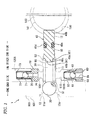
- a plunger pump 1 includes a pump body 100 having a cylinder hole 10, a lid member 20 for sealing the one end of the cylinder hole 10, a plunger 40 slidably attached within the cylinder hole 10, and a coil spring 50 which is disposed Within a pump chamber 30 and presses the plunger 40 on an eccentric cum 140 side, wherein one end of the plunger defines the pump chamber 30 between the one end and the lid member 20 and the other end of the plunger abuts against the eccentric cum 140 ("driving member" in claims).
- the plunger pump 1 is arranged in a manner that when the plunger 40 reciprocally moves in an axial direction within the cylinder 10, brake fluid sucked into the pump chamber 30 from a suction port 110 is discharged from the ejection port 120 of the pump chamber 30.
- the pump body 100 is a metal component of an almost rectangular parallelepiped shape to be mounted on a vehicle.
- a plurality of oil passages are formed within the pump body, and the pump body is provided with the cylinder hole 10 of a circular sectional shape into which the plunger pump 1 is inserted (see Fig. 2 ).
- the cylinder hole 10 has a circular sectional shape.
- the one end of the cylinder hole is opened at the one surface 101 of the pump body 100 and the other end thereof communicates with a bearing hole 130. That is, the cylinder hole 10 extends in the right direction from the one surface 101 of the pump body 100 toward the center portion thereof in Fig. 1 .
- a stepped large diameter portion 11 of a cylindrical shape is formed at a portion on the one end side (the one surface 101 side of the pump body 100) with respect to the center portion in the axis line direction of the cylinder hole 10.
- a small diameter portion of a cylindrical shape is formed at a portion on the other end side (the bearing hole 130 side) with respect to the center portion in the axis line direction of the cylinder hole 10.
- An opening portion 13 on the one end side of the cylinder hole 10 is formed to have a diameter larger than that of the large diameter portion 11 and is provided with an annular bottom portion 13a.
- a guide surface 13b formed in a tapered shape is formed at the inner peripheral portion of the bottom portion 13a.
- the lid member 20 of a metal spherical body is fit into the large diameter portion 11 of the cylinder hole 10 (see Fig. 2 ).
- the lid member 20 seals the one end of the cylinder hole 10.
- the outer diameter of the lid member 20 is formed to be slightly larger than the inner diameter of the large diameter portion 11 of the cylinder hole 10.
- the lid member 20 is pressed into the large diameter potion 11 of the cylinder hole 10.
- a retaining portion 11a for the lid member 20 is formed on the one end side of the cylinder hole 10 with respect to the center of the lid member 20.
- the retaining portion 11a is formed by plastically reforming the inner peripheral surface (hole wall portion) of the cylinder hole 10.
- the lid member 20 is pushed and pressed into the large diameter portion 11 from the opening portion 13 on the one end side of the cylinder hole 10 by using a jig J, whereby the lid member 20 is fit within the one end of the large diameter portion 11.
- the lid member 20 is pushed into the large diameter portion 11 while being guided along the guide surface 13b formed at the inner peripheral portion of the bottom portion 13a, the lid member 20 is pressed into the large diameter portion 11 in a state that the center of the lid member 20 and the center of the large diameter portion 11 are aligned.
- the bottom portion 13a is crushed from the opening portion 13 side by using the outer circumferential portion J1 of the jig J so that the bottom portion 13a of the opening portion 13 protrudes toward the inner direction of the large diameter portion 11, whereby the lid member 20 is locked by the inner peripheral surface of the large diameter portion 11 to thereby form the retaining portion 11a of the lid member 20 on the one end side of the cylinder hole 10 with respect to the center of the lid member 20.
- an eccentric cam 140 provided at the output shaft of an electric motor (not shows) attached to the pump body 100 is housed within the bearing hole 130.
- the center position of the eccentric cam 140 is eccentric with respect to the shaft center of the output shaft which is disposed coaxially as to the bearing hole 130.
- the eccentric cam 140 rotates around the shaft center of the output shaft in accordance with the rotation of the output shaft of the eccentric cam 140.
- the plunger 40 is a metal component having a circular sectional shape to be inserted into the small diameter portion 12 of the cylinder hole 10 (see Fig. 2 ).
- the one end 40a of the plunger protrudes into the large diameter portion 11 and the other end 40b thereof protrudes into the bearing hole 130.
- the outer periphery of the plunger 40 slides along the inner periphery of the small diameter portion 12.
- a seal groove 40c is formed along the entire circumferential periphery at the center position in the axial direction on the outer circumferential surface of the plunger 40 (see Fig. 2 ).
- An annular seal member 40d is fit into the seal groove 40c to thereby fluid-tightly seal between the outer circumferential surface of the plunger 40 and the inner circumferential surface of the small diameter portion 12.
- the pump chamber 30 is defined within the cylinder hole 10 by the inner circumferential surface of the large diameter portion 11 of the cylinder hole 10, the outer surface of the one end 40a of the plunger 40 protruded within the large diameter portion 11 of the cylinder hole 10, and the surface of the lid member 20.
- the end surface on the other end 40b side of the plunger 40 abuts against the cam surface 141 of the eccentric cam 140. Since the eccentric cam 140 rotates in an eccentric manner around the output shaft of the electric motor (not shown), when output shaft (not shown) of the electric motor is rotated, the plunger 40 is pushed by the cam surface 141 of the eccentric cam 140 and moves in the axial direction toward the pump chamber 30 side.
- a receiving portion 41 for receiving the other end of the coil spring 50 described later is formed at the end surface on the one end 40a side of the plunger 40.
- the receiving portion 41 includes an annular receiving surface 41a provided at the end surface of the plunger 40 and a projection portion 41b protrusively provided at the center portion of the end surface of the plunger 40.
- the coil spring 50 is disposed within the pump chamber 30 in a compressed state in a manner that the one end 51 abuts against the surface (spherical surface) of the lid member 20 and the other end 52 engages with the receiving portion 41 provided at the one end 40a of the plunger 40.
- a part of the surface of the lid member 20 enters into the opening portion of the one end 51 of the coil spring 50, whereby the one end of the coil spring 50 is guided by the surface (spherical surface) of the lid member 20.
- the shaft center of the coil spring 50 and the center of the lid member 20 are adjusted, so that the coil spring 50 and the lid member 20 are coaxially disposed.
- the other end 52 of the coil spring 50 abuts against the receiving surface 41a in a state that the projection portion 41b of the receiving portion 41 of the plunger 40 is fit into the opening portion of the other end, and hence the coil spring 50 and the plunger 40 are coaxially disposed.
- the one end 51 of the coil spring 50 is received by the spherical surface of the lid member 20 and the other end 52 of the coil spring 50 is received by the receiving portion 41 provided at the one end 40a of the plunger 40.
- the coil spring 50 presses the plunger 40 toward the eccentric cam 140 side, when the cam surface 141 of the eccentric cam 140 deviates toward a direction separating from the plunger 40 after the plunger 40 is pushed by the eccentric cam 140 and moves to the pump chamber 30 side, the coil spring moves the plunger 40 toward the eccentric cam 140 side. That is, the plunger 40 moves in the axial direction toward the eccentric cam 140 side by the pressing force from the coil spring 50. As a result, the end surface on the other end 40b side of the plunger 40 is kept in an abutted state against the cam surface 141.
- the suction port 110 and the ejection port 120 opened at the pump chamber 30 are formed at the inner circumferential surface of the large diameter portion 11 of the cylinder hole 10.
- the suction port 110 communicates with a suction fluid passage 110A formed within the pump body 100.
- the brake fluid is sucked into the pump chamber 30 from the suction fluid passage 110A via the suction port 110.
- the ejection port 120 communicates with an ejection fluid passage 120A formed within the pump body 100.
- the brake fluid within the pump chamber 30 is ejected to the ejection fluid passage 120A via the ejection port 120.
- the suction fluid passage 110A is provided with a suction valve 60 acting as a stop valve for allowing the brake fluid only to flow into the pump chamber 30.
- the suction valve 60 includes a cylindrical member 64 through which a suction hole 65 penetrates, a suction valve body 61 for sealing the opening portion on the pump chamber 30 side of the suction hole 65, a retainer 62 for housing the suction valve body 61 and a spring member 63 housed within the retainer 62.
- the cylindrical member 64 is a cylindrical metal component and is fit within the suction fluid passage 110A.
- a valve seat which diameter is enlarged in a funnel shape is formed at the opening edge potion on the pump chamber 30 side of the suction hole 65 which is formed at the center portion of the cylindrical member 64.
- the suction valve body 61 is a metal component of a spherical shape. The suction valve body seals the opening portion of the suction hole 65 when abutted against the valve seat of the suction hole 65.
- the retainer 62 is a cylindrical lid member having a bottom portion.
- the end portion on the pump chamber 30 side of the suction hole 65 is fit into the opening portion of the retainer 62.
- the suction valve body 61 is housed within the retainer 62.
- a plurality of communicating holes are formed in the retainer 62 to thereby communicate the retainer 62 with the suction fluid passage 110A.
- the spring member 63 is a coil spring disposed in a compressed state between the inner surface of the bottom portion of the retainer 62 and the suction valve body 61.
- the spring member presses the suction valve body 61 to the suction hole 65 side.
- the ejection fluid passage 120A is provided with an ejection valve 70 acting as a stop valve for allowing the brake fluid only to flow out from the pump chamber 30.
- the ejection valve 70 includes a cylindrical member 74 through which an ejection hole 75 penetrates, an ejection valve body 71 for sealing the opening portion on the pump chamber 30 side of the ejection hole 75, a retainer 72 for housing the ejection valve body 71 and a spring member 73 housed within the retainer 72.
- the ejection valve 70 is the stop valve having the same structure as the suction valve 60.
- a value obtained by subtracting the brake fluid pressure on the down stream side of the ejection fluid passage 120A from the brake fluid pressure on the upstream side (pump chamber 30 side) thereof becomes equal to or larger than a valve opening pressure (a biasing force of the spring member 73)
- the ejection valve body 71 separates from the ejection hole 75 of the cylindrical member 74 against the biasing force of the spring member 73 to thereby open the ejection valve 70.
- the pump chamber 30 When the capacity of the pump chamber 30 increases, the pump chamber 30 is placed in a negative pressure state. Thus, the suction valve 60 is opened, whereby the brake fluid is sucked into the pump chamber 30 from the suction fluid passage 110A via the suction port 110.
- the plunger 40 moves backwardly to thereby reach the end point (bottom dead center) of the other end side and the capacity of the pump chamber 30 becomes the maximum, the plunger 40 is pushed by the cam surface 141 of the eccentric cam 140 being rotated and hence moves again forwardly. Then, like the case of the aforesaid forward movement, the brake fluid within the pump chamber 30 is increased in its pressure and so ejected to the ejection fluid passage 120A.
- the plunger pump 1 configured in the aforesaid manner, as shown in Fig.1 , since the one end of the coil spring is received by the surface (spherical surface) of the lid member 20 as a sphere, the shaft center of the coil spring 50 and the center of the lid member 20 are automatically adjusted so as to be aligned and so the coil spring 50 is disposed at the center portion of the pump chamber 30.
- the extensible coil spring '50 can be guided while the coil spring 50 is prevented from being rubbed against the inner circumferential surface of the pump chamber 30, and so swarf can be prevented from being generated within the pump chamber 30.
- the lid member 20 is configured in a simple shape, that is, a sphere, the assembling method of the lid member to the cylinder hole 10 is not limited. Thus, the assembling property of the lid member to the cylinder hole 10 can be improved.
- the lid member 20 is pressed into the cylinder hole 10, and the retaining portion 11a for the lid member 20 is formed on the one end side of the cylinder hole 10 with respect to the center of the lid member 20.
- the lid member 20 as the sphere can be surely fixed with respect to the cylinder hole 10, the one end of the cylinder hole 10 can be sealed.
- the both ends of the coil spring 50 can be disposed at the center portion of the pump chamber 30.
- the coil spring 50 can be surely prevented from being rubbed against the inner circumferential surface of the pump chamber 30.
- the seal member 40d is fit into the seal groove 40c formed on the outer circumferential surface of the plunger 40.
- an annular seal member 40e may be fit on the outer circumferential surface of the plunger 40A.
- the seal member 40e is disposed between two annular stoppers 11a and 11b which are fit in the large diameter portion 11 of the cylinder hole 10 to thereby position the seal member 40e by the stoppers 11a, 11b.
- the seal member 40e is fit on the outer circumferential surface of the plunger 40A, the length of the plunger 40A in the axial direction can be made short and hence the plunger pump 1A can be made small in its size.
- a seal member 40e may be fit on the outer circumferential surface of a plunger 40B and a receiving portion 42 may be formed separately from the plunger 40B.
- the receiving portion 42 is formed in a cylindrical shape having a bottom portion and configured in a manner that the bottom portion thereof is provided with a projection portion 42a which is to be inserted into the opening portion on the other end 52 side of the coil spring 50 and the opening portion of the receiving portion 42 is fit on the one end 40a of the plunger 40B. That is, the receiving portion 42 covers the one end 40a of the plunger 40B.
- the shape of the one end 40a side of the plunger 40B is same as that of the other end 40b side thereof.
- the assembling direction of the plunger to the cylinder hole 10 is not limited, the assembling property to the cylinder hole 10 can be improved.
- the extensible coil spring 50 can be surely prevented from being rubbed against the inner circumferential surface of the pump chamber 30. Further, the receiving portion 43 of the plunger 40C can be processed easily.
- two coil springs 50a, 50b may be disposed within the pump chamber 30.
- the two coil springs 50a, 50b are disposed in the radial direction in a manner that the other coil spring 50a is inserted into the one coil spring 50b, whereby the one ends 51, 51 of the coil springs 50a, 50b are received by the surface of the lid member 20.
- the shaft centers of the coil springs 50a, 50b and the center of the lid member 20 are automatically adjusted so as to be aligned and so the coil springs 50a, 50b are disposed at the center portion of the pump chamber 30.
- the pressing force for pressing the plunger 40B to the eccentric cam 140 side is shared by the coil springs 50a, 50b, the length and the diameter of each of the coil springs 50a, 50b can be made small, so that the plunger pump 1D can be miniaturized.
- each of the coil springs 50a, 50b can be made small, the capacity within the pump chamber 30 can be reduced, whereby the ejection efficiency of the plunger pump 1D can be enhanced.
- the plunger pump 1D shown in Fig. 7 employs the two coil springs 50a, 50b, the three or more coil springs may be employed.
- the seal member 40e is fit on the outer circumferential surface of the plunger 40B and the receiving portion 42 for receiving the other ends 52, 52 of the coil springs 50a, 50b is formed separately from the plunger 40B
- the configurations of the seal member and the receiving portion are not limited thereto.
- the invention may employ such configurations that the seal member 40e is fit into the seal groove of the plunger 40B and that a receiving portion is formed at the one end 40a of the plunger 40B.
Landscapes
- Engineering & Computer Science (AREA)
- Mechanical Engineering (AREA)
- General Engineering & Computer Science (AREA)
- Physics & Mathematics (AREA)
- Fluid Mechanics (AREA)
- Transportation (AREA)
- Details Of Reciprocating Pumps (AREA)
- Reciprocating Pumps (AREA)
Abstract
Description
- The present invention relates to a plunger pump.
- There has been provided a plunger pump in which a driving member such as an eccentric cum reciprocally moves a plunger (also called a piston) within a pump chamber in the axial direction to thereby eject fluid, sucked into the pump chamber from a suction port, from an ejection port of the pump chamber.
- As an example of such the plunger pump, there is one which is arranged to include a pump body having a cylinder hole, a lid member for sealing the one end of the cylinder hole, a plunger slidably attached within the cylinder hole, and a coil spring which is disposed within a pump chamber and presses the plunger on a driving member side, wherein one end of the plunger defines the pump chamber between the one end and the lid member, the other end of the plunger abuts against the driving member, and one end of the coil spring is received by the flat surface of the lid member, as disclosed in
JP-A-11-43034 - According to this plunger pump, the coil spring disposed within the pump chamber is formed in a manner that the outer diameter thereof coincides with the inner diameter of the pump chamber so that the extensible coil spring is guided along the inner peripheral surface of the pump chamber. There is another configuration that a projection portion formed at the lid member is inserted into the opening portion of the coil spring to thereby guide the coil spring by the projection portion.
- According to the aforesaid plunger pump of the related art, since the coil spring contacts with the inner peripheral surface of the pump chamber or the projection portion of the lid member, swarf may be generated within the pump chamber due to a fact that the extensible coil spring rubs against the inner circumferential surface of the pump chamber or the projection portion of the lid member.
- The invention intends to solve the aforesaid problem and an object of the invention is to provide a plunger pump which can guide an extensible coil spring while the coil spring is prevented from expanding and contracting within a pump chamber from being rubbed with other member and also can improve a performance of assembling to a cylinder hole.
- According to an aspect of the invention, there is provided a plunger pump including: a pump body having a cylinder hole; a lidmember configured to seal one end of the cylinder hole; a plunger which is slidably attached within the cylinder hole, one end of the plunger defining a pump chamber between the one end and the lid member and the other end of the plunger abutting against a driving member; and a coil spring which is disposed within the pump chamber and presses the plunger toward the driving member side, wherein: when the plunger reciprocally moves in an axial direction within the cylinder hole, fluid sucked into the pump chamber from a suction port is ejected from an ejection port of the pump chamber; and the lid member has a spherical shape and one end of the coil spring is received by a surface of the lid member.
- According to this configuration, since the one end of the coil spring is received by the surface (spherical surface) of the lid member, the shaft center of the coil spring and the center of the lid member are automatically adjusted so as to be aligned and so the coil spring is disposed at the center portion of the pump chamber. Thus, the extensible coil spring can be guided while the extensible coil spring is prevented from being rubbed against other member.
- Further, since the lidmember is configured in a simple shape, that is, a sphere, the assembling direction thereof to the cylinder hole is not limited. Thus, the assembling property of the lid member to the cylinder hole can be improved.
- The lid member may be pressed into the cylinder hole, a retaining portion for the lid member may be formed at the one end side of the cylinder hole with respect to a center of the lid member, and the retaining portion may be formed by plastically deforming an inner circumferential surface of the cylinder hole.
- According to this configuration, the lid member as the sphere can be surely fixed to the cylinder hole to thereby seal the one end of the cylinder hole.
- The plunger may be provided with a receiving portion configured to receive the other end of the coil spring, and the receiving portion may have a receiving surface where the other end of the coil spring abuts and a projection portion which is inserted into an opening portion at the other end of the coil spring.
- The plunger may be provided with a receiving portion configured to receive the other end of the coil spring, and the receiving portion may have a spherical surface where the other end of the coil spring abuts.
- According to these configurations, since the receiving portion of the plunger receives the other end of the coil spring, the both ends of the coil spring can be disposed at the center portion of the pump chamber. Thus, the extensible coil spring can be surely prevented from being rubbed against other member.
- Further, when the receiving portion has the spherical surface, the receiving portion of the plunger can be processed easily.
- According to another aspect of the invention, there is provided a plunger pump including: a pump body having a cylinder hole; a lid member configured to seal one end of the cylinder hole; a plunger which is slidably attached within the cylinder hole, one end of the plunger defining a pump chamber between the one end and the lid member and the other end of the plunger abutting against a driving member; and a plurality of the coil springs arranged in a radial direction within the pump chamber, the plurality of the coil springs pressing the plunger toward the driving member side, wherein: when the plunger reciprocally moves in an axial direction within the cylinder hole, fluid sucked into the pump chamber from a suction port is ejected from an ejection port of the pump chamber; and the lidmember has a spherical shape and one ends of the plurality of the coil springs are received by a surface of the lid member.
- Even in the case where the lid member is configured to receive the one ends of the plurality of the coil springs by the surface thereof, since the one ends of the plurality of the coil springs are commonly received by the surface (spherical surface) of the lid member, the shaft center of each of the coil springs and the center of the lid member are automatically adjusted so as to be aligned and so the coil springs are disposed at the center portion of the pump chamber.
- Further, since the pressing force for pressing the plunger to the driving member side is shared by the respective coil springs, the length and the diameter of each of the coil springs can be made small, so that the plunger pump can be miniaturized.
- Furthermore, since the length and the diameter of each of the coil springs can be made small, the capacity within the pump chamber can be reduced, whereby the ejection efficiency of the plunger pump can be enhanced.
- According to the plunger pump of the invention, the shaft center of the coil spring and the center of the lid member are automatically adjusted so as to be aligned and so the coil spring is disposed at the center portion of the pump chamber. Thus, the extensible coil spring can be guided while the extensible coil spring is prevented from being rubbed against other member.
- Further, since the assembling direction of the lid member to the cylinder hole is not limited, the assembling property of the lid member to the cylinder hole can be improved.
- The present invention will become more fully understood from the detailed description given hereinbelow and the accompanying drawing which is given by way of illustration only, and thus is not limitative of the present invention and wherein:
-
Fig. 1 is a side sectional view showing a plunger pump according to an embodiment; -
Fig. 2 is an exploded perspective view showing the plunger pump according to the embodiment; -
Figs. 3A and 3B are diagrams showing a procedure of attaching a lid member to a cylinder hole according to the embodiment, in whichFig. 3A is a side sectional view showing a state where the lid member is pressed into the cylinder hole, andFig. 3B is a side sectional view showing a state where the lid member is locked by the inner peripheral surface of the cylinder hole; -
Fig. 4 is a side sectional view showing a plunger pump according to another embodiment, in which a seal member is disposed outside of a plunger; -
Fig. 5 is a side sectional view showing a plunger pump according to still another embodiment, in which a receiving portion is attached to a plunger; -
Fig. 6 is a side sectional view showing aplunger pump according to still another embodiment, in which a receiving portion has a spherical shape; and -
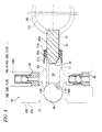
Fig. 7 is a side sectional view showing a plunger pump according to still another embodiment, in which a plurality of coil springs are employed. - Next, an embodiment of the invention will be explained in detail with reference to accompanying drawings.
- The embodiment will be explained, as an example, as to a plunger pump which is used as a hydraulic pressure generating device for a brake fluid pressure control apparatus to be mounted on a vehicle such as an automobile.
- In the following explanation, one end side and the other end side correspond to the left and right side in
Fig, 1 , respectively. - As shown in
Fig. 1 , aplunger pump 1 includes apump body 100 having acylinder hole 10, alid member 20 for sealing the one end of thecylinder hole 10, aplunger 40 slidably attached within thecylinder hole 10, and acoil spring 50 which is disposed Within apump chamber 30 and presses theplunger 40 on aneccentric cum 140 side, wherein one end of the plunger defines thepump chamber 30 between the one end and thelid member 20 and the other end of the plunger abuts against the eccentric cum 140 ("driving member" in claims). Theplunger pump 1 is arranged in a manner that when theplunger 40 reciprocally moves in an axial direction within thecylinder 10, brake fluid sucked into thepump chamber 30 from asuction port 110 is discharged from theejection port 120 of thepump chamber 30. - The
pump body 100 is a metal component of an almost rectangular parallelepiped shape to be mounted on a vehicle. A plurality of oil passages (not shown) are formed within the pump body, and the pump body is provided with thecylinder hole 10 of a circular sectional shape into which theplunger pump 1 is inserted (seeFig. 2 ). - The
cylinder hole 10 has a circular sectional shape. The one end of the cylinder hole is opened at the onesurface 101 of thepump body 100 and the other end thereof communicates with abearing hole 130. That is, thecylinder hole 10 extends in the right direction from the onesurface 101 of thepump body 100 toward the center portion thereof inFig. 1 . - A stepped
large diameter portion 11 of a cylindrical shape is formed at a portion on the one end side (the onesurface 101 side of the pump body 100) with respect to the center portion in the axis line direction of thecylinder hole 10. A small diameter portion of a cylindrical shape is formed at a portion on the other end side (thebearing hole 130 side) with respect to the center portion in the axis line direction of thecylinder hole 10. Anopening portion 13 on the one end side of thecylinder hole 10 is formed to have a diameter larger than that of thelarge diameter portion 11 and is provided with anannular bottom portion 13a. Aguide surface 13b formed in a tapered shape is formed at the inner peripheral portion of thebottom portion 13a. - The
lid member 20 of a metal spherical body is fit into thelarge diameter portion 11 of the cylinder hole 10 (seeFig. 2 ). Thelid member 20 seals the one end of thecylinder hole 10. The outer diameter of thelid member 20 is formed to be slightly larger than the inner diameter of thelarge diameter portion 11 of thecylinder hole 10. Thelid member 20 is pressed into thelarge diameter potion 11 of thecylinder hole 10. Further, aretaining portion 11a for thelid member 20 is formed on the one end side of thecylinder hole 10 with respect to the center of thelid member 20. Theretaining portion 11a is formed by plastically reforming the inner peripheral surface (hole wall portion) of thecylinder hole 10. - The explanation will be made as to a procedure of attaching the
lid member 20 at thelarge diameter portion 11 of thecylinder hole 10. - First, as shown in
Fig. 3A , thelid member 20 is pushed and pressed into thelarge diameter portion 11 from the openingportion 13 on the one end side of thecylinder hole 10 by using a jig J, whereby thelid member 20 is fit within the one end of thelarge diameter portion 11. In this case, since thelid member 20 is pushed into thelarge diameter portion 11 while being guided along theguide surface 13b formed at the inner peripheral portion of thebottom portion 13a, thelid member 20 is pressed into thelarge diameter portion 11 in a state that the center of thelid member 20 and the center of thelarge diameter portion 11 are aligned. - Then, as shown in
Fig. 3B , while further pressing theportion 20 into the other end side of thelarge diameter portion 11, thebottom portion 13a is crushed from the openingportion 13 side by using the outer circumferential portion J1 of the jig J so that thebottom portion 13a of the openingportion 13 protrudes toward the inner direction of thelarge diameter portion 11, whereby thelid member 20 is locked by the inner peripheral surface of thelarge diameter portion 11 to thereby form the retainingportion 11a of thelid member 20 on the one end side of thecylinder hole 10 with respect to the center of thelid member 20. - As shown in
Fig. 1 , aneccentric cam 140 provided at the output shaft of an electric motor (not shows) attached to thepump body 100 is housed within thebearing hole 130. The center position of theeccentric cam 140 is eccentric with respect to the shaft center of the output shaft which is disposed coaxially as to thebearing hole 130. Theeccentric cam 140 rotates around the shaft center of the output shaft in accordance with the rotation of the output shaft of theeccentric cam 140. - The
plunger 40 is a metal component having a circular sectional shape to be inserted into thesmall diameter portion 12 of the cylinder hole 10 (seeFig. 2 ). The oneend 40a of the plunger protrudes into thelarge diameter portion 11 and theother end 40b thereof protrudes into thebearing hole 130. When theplunger 40 is reciprocally moved in the axial direction within thesmall diameter portion 12 of thecylinder hole 10, the outer periphery of theplunger 40 slides along the inner periphery of thesmall diameter portion 12. - A
seal groove 40c is formed along the entire circumferential periphery at the center position in the axial direction on the outer circumferential surface of the plunger 40 (seeFig. 2 ). Anannular seal member 40d is fit into theseal groove 40c to thereby fluid-tightly seal between the outer circumferential surface of theplunger 40 and the inner circumferential surface of thesmall diameter portion 12. - The
pump chamber 30 is defined within thecylinder hole 10 by the inner circumferential surface of thelarge diameter portion 11 of thecylinder hole 10, the outer surface of the oneend 40a of theplunger 40 protruded within thelarge diameter portion 11 of thecylinder hole 10, and the surface of thelid member 20. - The end surface on the
other end 40b side of theplunger 40 abuts against thecam surface 141 of theeccentric cam 140. Since theeccentric cam 140 rotates in an eccentric manner around the output shaft of the electric motor (not shown), when output shaft (not shown) of the electric motor is rotated, theplunger 40 is pushed by thecam surface 141 of theeccentric cam 140 and moves in the axial direction toward thepump chamber 30 side. - A receiving
portion 41 for receiving the other end of thecoil spring 50 described later is formed at the end surface on the oneend 40a side of theplunger 40. The receivingportion 41 includes anannular receiving surface 41a provided at the end surface of theplunger 40 and aprojection portion 41b protrusively provided at the center portion of the end surface of theplunger 40. - The
coil spring 50 is disposed within thepump chamber 30 in a compressed state in a manner that the oneend 51 abuts against the surface (spherical surface) of thelid member 20 and theother end 52 engages with the receivingportion 41 provided at the oneend 40a of theplunger 40. - A part of the surface of the
lid member 20 enters into the opening portion of the oneend 51 of thecoil spring 50, whereby the one end of thecoil spring 50 is guided by the surface (spherical surface) of thelid member 20. Thus, since the shaft center of thecoil spring 50 and the center of thelid member 20 are adjusted, so that thecoil spring 50 and thelid member 20 are coaxially disposed. - The
other end 52 of thecoil spring 50 abuts against the receivingsurface 41a in a state that theprojection portion 41b of the receivingportion 41 of theplunger 40 is fit into the opening portion of the other end, and hence thecoil spring 50 and theplunger 40 are coaxially disposed. - In this manner, according to the
plunger pump 1 of this embodiment, the oneend 51 of thecoil spring 50 is received by the spherical surface of thelid member 20 and theother end 52 of thecoil spring 50 is received by the receivingportion 41 provided at the oneend 40a of theplunger 40. - Since the
coil spring 50 presses theplunger 40 toward theeccentric cam 140 side, when thecam surface 141 of theeccentric cam 140 deviates toward a direction separating from theplunger 40 after theplunger 40 is pushed by theeccentric cam 140 and moves to thepump chamber 30 side, the coil spring moves theplunger 40 toward theeccentric cam 140 side. That is, theplunger 40 moves in the axial direction toward theeccentric cam 140 side by the pressing force from thecoil spring 50. As a result, the end surface on theother end 40b side of theplunger 40 is kept in an abutted state against thecam surface 141. - The
suction port 110 and theejection port 120 opened at thepump chamber 30 are formed at the inner circumferential surface of thelarge diameter portion 11 of thecylinder hole 10. - The
suction port 110 communicates with asuction fluid passage 110A formed within thepump body 100. The brake fluid is sucked into thepump chamber 30 from thesuction fluid passage 110A via thesuction port 110. - The
ejection port 120 communicates with anejection fluid passage 120A formed within thepump body 100. The brake fluid within thepump chamber 30 is ejected to theejection fluid passage 120A via theejection port 120. - The
suction fluid passage 110A is provided with asuction valve 60 acting as a stop valve for allowing the brake fluid only to flow into thepump chamber 30. - The
suction valve 60 includes acylindrical member 64 through which asuction hole 65 penetrates, asuction valve body 61 for sealing the opening portion on thepump chamber 30 side of thesuction hole 65, aretainer 62 for housing thesuction valve body 61 and aspring member 63 housed within theretainer 62. - The
cylindrical member 64 is a cylindrical metal component and is fit within thesuction fluid passage 110A. A valve seat which diameter is enlarged in a funnel shape is formed at the opening edge potion on thepump chamber 30 side of thesuction hole 65 which is formed at the center portion of thecylindrical member 64. Thesuction valve body 61 is a metal component of a spherical shape. The suction valve body seals the opening portion of thesuction hole 65 when abutted against the valve seat of thesuction hole 65. - The
retainer 62 is a cylindrical lid member having a bottom portion. The end portion on thepump chamber 30 side of thesuction hole 65 is fit into the opening portion of theretainer 62. Thesuction valve body 61 is housed within theretainer 62. A plurality of communicating holes are formed in theretainer 62 to thereby communicate theretainer 62 with thesuction fluid passage 110A. - The
spring member 63 is a coil spring disposed in a compressed state between the inner surface of the bottom portion of theretainer 62 and thesuction valve body 61. The spring member presses thesuction valve body 61 to thesuction hole 65 side. - When a value obtained by subtracting the brake fluid pressure on the upstream side (pump
chamber 30 side) of thesuction fluid passage 110A from the brake fluid pressure on the downstream side thereof becomes equal to or larger than a valve opening pressure (a biasing force of the spring member 63), thesuction valve body 61 separates from thesuction hole 65 of thecylindrical member 64 against the biasing force of thespring member 63 to thereby open thesuction valve 60. - The
ejection fluid passage 120A is provided with anejection valve 70 acting as a stop valve for allowing the brake fluid only to flow out from thepump chamber 30. - The
ejection valve 70 includes acylindrical member 74 through which anejection hole 75 penetrates, anejection valve body 71 for sealing the opening portion on thepump chamber 30 side of theejection hole 75, aretainer 72 for housing theejection valve body 71 and aspring member 73 housed within theretainer 72. - The
ejection valve 70 is the stop valve having the same structure as thesuction valve 60. When a value obtained by subtracting the brake fluid pressure on the down stream side of theejection fluid passage 120A from the brake fluid pressure on the upstream side (pumpchamber 30 side) thereof becomes equal to or larger than a valve opening pressure (a biasing force of the spring member 73), theejection valve body 71 separates from theejection hole 75 of thecylindrical member 74 against the biasing force of thespring member 73 to thereby open theejection valve 70. - Next, the explanation will be made as to the operation of the
plunger pump 1 according to the embodiment. - As shown in
Fig. 1 , in a state that the brake fluid is filled within thepump chamber 30, when theplunger 40 is pushed by thecam surface 141 of theeccentric cam 140 being rotated and hence moves forwardly in the axial direction toward the one end side (lid member 20 side), the capacity of thepump chamber 30 reduces and so the fluid pressure of the brake fluid within thepump chamber 30 increases. Thus, since theejection valve 70 is opened, the brake fluid within thepump chamber 30 is ejected to theejection fluid passage 120A via theejection port 120. - Succeedingly, after the
plunger 40 reaches the end point (top dead center) of the one end side and the capacity of thepump chamber 30 becomes the minimum, thecam surface 141 of theeccentric cam 140 being rotated deviates toward a direction separating from theplunger 40. In this case, theplunger 40 moves backwardly in the axial direction toward theeccentric cam 140 side by the pressing force from thecoil spring 50 to thereby increase the capacity of thepump chamber 30. - When the capacity of the
pump chamber 30 increases, thepump chamber 30 is placed in a negative pressure state. Thus, thesuction valve 60 is opened, whereby the brake fluid is sucked into thepump chamber 30 from thesuction fluid passage 110A via thesuction port 110. - Then, after the
plunger 40 moves backwardly to thereby reach the end point (bottom dead center) of the other end side and the capacity of thepump chamber 30 becomes the maximum, theplunger 40 is pushed by thecam surface 141 of theeccentric cam 140 being rotated and hence moves again forwardly. Then, like the case of the aforesaid forward movement, the brake fluid within thepump chamber 30 is increased in its pressure and so ejected to theejection fluid passage 120A. - According to the
plunger pump 1 configured in the aforesaid manner, as shown inFig.1 , since the one end of the coil spring is received by the surface (spherical surface) of thelid member 20 as a sphere, the shaft center of thecoil spring 50 and the center of thelid member 20 are automatically adjusted so as to be aligned and so thecoil spring 50 is disposed at the center portion of thepump chamber 30. Thus, the extensible coil spring '50 can be guided while thecoil spring 50 is prevented from being rubbed against the inner circumferential surface of thepump chamber 30, and so swarf can be prevented from being generated within thepump chamber 30. - Further, since the
lid member 20 is configured in a simple shape, that is, a sphere, the assembling method of the lid member to thecylinder hole 10 is not limited. Thus, the assembling property of the lid member to thecylinder hole 10 can be improved. - Furthermore, the
lid member 20 is pressed into thecylinder hole 10, and the retainingportion 11a for thelid member 20 is formed on the one end side of thecylinder hole 10 with respect to the center of thelid member 20. Thus, since thelid member 20 as the sphere can be surely fixed with respect to thecylinder hole 10, the one end of thecylinder hole 10 can be sealed. - Furthermore, since the receiving
portion 41 of theplunger 40 receives the other end of thecoil spring 50, the both ends of thecoil spring 50 can be disposed at the center portion of thepump chamber 30. Thus, thecoil spring 50 can be surely prevented from being rubbed against the inner circumferential surface of thepump chamber 30. - Although the embodiment according to the invention is explained above, the invention is not limited to the aforesaid embodiment and may be suitably changed in a range not departing from the gist thereof.
- For example, in the aforesaid embodiment, as shown in
Fig. 1 , theseal member 40d is fit into theseal groove 40c formed on the outer circumferential surface of theplunger 40. However, like aplunger pump 1A shown inFig. 4 , without forming a seal groove on the outer circumferential surface of a plunger 40A, anannular seal member 40e may be fit on the outer circumferential surface of the plunger 40A. According to this configuration, theseal member 40e is disposed between twoannular stoppers 11a and 11b which are fit in thelarge diameter portion 11 of thecylinder hole 10 to thereby position theseal member 40e by thestoppers 11a, 11b. - In this manner, since the
seal member 40e is fit on the outer circumferential surface of the plunger 40A, the length of the plunger 40A in the axial direction can be made short and hence theplunger pump 1A can be made small in its size. - Further, like a
plunger pump 1B shown inFig. 5 , aseal member 40e may be fit on the outer circumferential surface of aplunger 40B and a receivingportion 42 may be formed separately from theplunger 40B. The receivingportion 42 is formed in a cylindrical shape having a bottom portion and configured in a manner that the bottom portion thereof is provided with aprojection portion 42a which is to be inserted into the opening portion on theother end 52 side of thecoil spring 50 and the opening portion of the receivingportion 42 is fit on the oneend 40a of theplunger 40B. That is, the receivingportion 42 covers the oneend 40a of theplunger 40B. - According to this configuration, the shape of the one
end 40a side of theplunger 40B is same as that of theother end 40b side thereof. Thus, at the time of assembling theplunger 40B to thecylinder hole 10, since the assembling direction of the plunger to thecylinder hole 10 is not limited, the assembling property to thecylinder hole 10 can be improved. - Further, like a plunger pump 1C shown in
Fig. 6 , in the case where the receivingportion 43 of a plunger 40C has aspherical surface 43a, when theother end 52 of thecoil spring 50 is received by thespherical surface 43a, the shaft center of thecoil spring 50 and the center of thespherical surface 43a of the receivingportion 43 are automatically adjusted so as to be aligned and so theother end 52 of thecoil spring 50 is disposed at the center portion of thepump chamber 30. - According to this configuration, since the both ends 51, 52 of the
coil spring 50 are disposed at the center position of thepump chamber 30, theextensible coil spring 50 can be surely prevented from being rubbed against the inner circumferential surface of thepump chamber 30. Further, the receivingportion 43 of the plunger 40C can be processed easily. - Further, like a
plunger pump 1D shown inFig. 7 , twocoil springs pump chamber 30. According to thisplunger pump 1D, the twocoil springs other coil spring 50a is inserted into the onecoil spring 50b, whereby the one ends 51, 51 of thecoil springs lid member 20. - According to this configuration, since the one ends 51, 51 of the
coil springs lid member 20, the shaft centers of thecoil springs lid member 20 are automatically adjusted so as to be aligned and so thecoil springs pump chamber 30. - Further, since the pressing force for pressing the
plunger 40B to theeccentric cam 140 side is shared by thecoil springs coil springs plunger pump 1D can be miniaturized. - Furthermore, since the length and the diameter of each of the
coil springs pump chamber 30 can be reduced, whereby the ejection efficiency of theplunger pump 1D can be enhanced. - Although the
plunger pump 1D shown inFig. 7 employs the twocoil springs - Further, according to the
plunger pump 1D shown inFig. 7 , although theseal member 40e is fit on the outer circumferential surface of theplunger 40B and the receivingportion 42 for receiving the other ends 52, 52 of thecoil springs plunger 40B, the configurations of the seal member and the receiving portion are not limited thereto. For example, the invention may employ such configurations that theseal member 40e is fit into the seal groove of theplunger 40B and that a receiving portion is formed at the oneend 40a of theplunger 40B.
Claims (5)
- A plunger pump comprising:a pump body having a cylinder hole;a lid member configured to seal one end of the cylinder hole;a plunger which is slidably attached within the cylinder hole, one end of the plunger defining a pump chamber between the one end and the lid member and the other end of the plunger abutting against a driving member; anda coil spring which is disposed within the pump chamber and presses the plunger toward the driving member side, wherein:when the plunger reciprocally moves in an axial direction within the cylinder hole, fluid sucked into the pump chamber from a suction port is ejected from an ejection port of the pump chamber; andthe lid member has a spherical shape and one end of the coil spring is received by a surface of the lid member.
- The plunger pump according to claim 1, wherein:the lid member is pressed into the cylinder hole;a retaining portion for the lid member is formed at the one end side of the cylinder hole with respect to a center of the lid member; andthe retaining portion is formed by plastically deforming an inner circumferential surface of the cylinder hole.
- The plunger pump according to claim 1 or 2, wherein:the plunger is provided with a receiving portion configured to receive the other end of the coil spring; andthe receiving portion has a receiving surface where the other end of the coil spring abuts and a projection portion which is inserted into an opening portion at the other end of the coil spring.
- The plunger pump according to claim 1 or 2, wherein:the plunger is provided with a receiving portion configured to receive the other end of the coil spring; andthe receiving portion has a spherical surface where the other end of the coil spring abuts.
- A plunger pump comprising:a pump body having a cylinder hole;a lid member configured to seal one end of the cylinder hole;a plunger which is slidably attached within the cylinder hole, one end of the plunger defining a pump chamber between the one end and the lid member and the other end of the plunger abutting against a driving member; anda plurality of the coil springs arranged in a radial direction within the pump chamber, the plurality of the coil springs pressing the plunger toward the driving member side, wherein:when the plunger reciprocally moves in an axial direction within the cylinder hole, fluid sucked into the pump chamber from a suction port is ejected from an ejection port of the pump chamber; andthe lid member has a spherical shape and one ends of the plurality of the coil springs are received by a surface of the lid member.
Applications Claiming Priority (1)
| Application Number | Priority Date | Filing Date | Title |
|---|---|---|---|
| JP2009215243A JP4871381B2 (en) | 2009-09-17 | 2009-09-17 | Plunger pump |
Publications (3)
| Publication Number | Publication Date |
|---|---|
| EP2306012A2 true EP2306012A2 (en) | 2011-04-06 |
| EP2306012A3 EP2306012A3 (en) | 2014-04-30 |
| EP2306012B1 EP2306012B1 (en) | 2018-01-24 |
Family
ID=43066892
Family Applications (1)
| Application Number | Title | Priority Date | Filing Date |
|---|---|---|---|
| EP10177315.8A Not-in-force EP2306012B1 (en) | 2009-09-17 | 2010-09-17 | Plunger pump |
Country Status (2)
| Country | Link |
|---|---|
| EP (1) | EP2306012B1 (en) |
| JP (1) | JP4871381B2 (en) |
Cited By (6)
| Publication number | Priority date | Publication date | Assignee | Title |
|---|---|---|---|---|
| CN102853238A (en) * | 2012-03-21 | 2013-01-02 | 马鞍山友邦重工机械有限公司 | Plunger pump used for planomiller mill head box |
| CN103939721A (en) * | 2014-05-15 | 2014-07-23 | 常州机电职业技术学院 | Volumetric motor lubricating oil pump |
| CN104832392A (en) * | 2015-05-20 | 2015-08-12 | 贵州珍酒酿酒有限公司 | Pressure stabilizing pump for white spirit microporous membrane filtration |
| GB2538287A (en) * | 2015-05-14 | 2016-11-16 | Gm Global Tech Operations Llc | Method and system for operating a cam-driven pump |
| CN109630799A (en) * | 2019-01-18 | 2019-04-16 | 湖南和广生物科技有限公司 | High-pressure fluid weakening constant-current stabilizer |
| US10359030B2 (en) | 2011-11-17 | 2019-07-23 | Nissin Kogyo Co., Ltd. | Plunger pump |
Families Citing this family (2)
| Publication number | Priority date | Publication date | Assignee | Title |
|---|---|---|---|---|
| JP5702687B2 (en) * | 2011-08-23 | 2015-04-15 | 日信工業株式会社 | Plunger pump and method for manufacturing base for plunger pump |
| KR102435946B1 (en) | 2021-11-01 | 2022-08-24 | 주식회사 미코바이오메드 | Plunger and module moving solution |
Citations (1)
| Publication number | Priority date | Publication date | Assignee | Title |
|---|---|---|---|---|
| JPH1143034A (en) | 1997-07-28 | 1999-02-16 | Denso Corp | Brake fluid pressure control device |
Family Cites Families (5)
| Publication number | Priority date | Publication date | Assignee | Title |
|---|---|---|---|---|
| DE3126917C2 (en) * | 1981-07-08 | 1984-06-14 | Zahnradfabrik Friedrichshafen Ag, 7990 Friedrichshafen | Radial piston pump |
| DE4107979C2 (en) * | 1991-03-13 | 1998-07-09 | Bosch Gmbh Robert | Hydraulic high pressure pump for motor vehicle brake systems |
| JPH10507982A (en) * | 1993-07-23 | 1998-08-04 | アイティーティー・オートモーティブ・ヨーロップ・ゲーエムベーハー | Hydraulic brake system with brake slip control and traction slip control |
| JP3706760B2 (en) * | 1999-01-11 | 2005-10-19 | 日信工業株式会社 | Plunger type hydraulic pump |
| JP4960278B2 (en) * | 2008-02-28 | 2012-06-27 | 日立オートモティブシステムズ株式会社 | Reciprocating pump |
-
2009
- 2009-09-17 JP JP2009215243A patent/JP4871381B2/en not_active Expired - Fee Related
-
2010
- 2010-09-17 EP EP10177315.8A patent/EP2306012B1/en not_active Not-in-force
Patent Citations (1)
| Publication number | Priority date | Publication date | Assignee | Title |
|---|---|---|---|---|
| JPH1143034A (en) | 1997-07-28 | 1999-02-16 | Denso Corp | Brake fluid pressure control device |
Cited By (8)
| Publication number | Priority date | Publication date | Assignee | Title |
|---|---|---|---|---|
| US10359030B2 (en) | 2011-11-17 | 2019-07-23 | Nissin Kogyo Co., Ltd. | Plunger pump |
| CN102853238A (en) * | 2012-03-21 | 2013-01-02 | 马鞍山友邦重工机械有限公司 | Plunger pump used for planomiller mill head box |
| CN103939721A (en) * | 2014-05-15 | 2014-07-23 | 常州机电职业技术学院 | Volumetric motor lubricating oil pump |
| GB2538287A (en) * | 2015-05-14 | 2016-11-16 | Gm Global Tech Operations Llc | Method and system for operating a cam-driven pump |
| US9874151B2 (en) | 2015-05-14 | 2018-01-23 | GM Global Technology Operatons LLC | Method and system for operating a cam-driven pump |
| CN104832392A (en) * | 2015-05-20 | 2015-08-12 | 贵州珍酒酿酒有限公司 | Pressure stabilizing pump for white spirit microporous membrane filtration |
| CN109630799A (en) * | 2019-01-18 | 2019-04-16 | 湖南和广生物科技有限公司 | High-pressure fluid weakening constant-current stabilizer |
| CN109630799B (en) * | 2019-01-18 | 2024-05-03 | 湖南和广生物科技有限公司 | High-pressure fluid vibration-eliminating and flow-stabilizing device |
Also Published As
| Publication number | Publication date |
|---|---|
| EP2306012A3 (en) | 2014-04-30 |
| JP2011064129A (en) | 2011-03-31 |
| EP2306012B1 (en) | 2018-01-24 |
| JP4871381B2 (en) | 2012-02-08 |
Similar Documents
| Publication | Publication Date | Title |
|---|---|---|
| EP2306012B1 (en) | Plunger pump | |
| JP5477614B2 (en) | Valve structure | |
| JP4143841B2 (en) | Piston pump | |
| CN103717873A (en) | Fuel pump | |
| US11773848B2 (en) | Cartridge vane pump and pump device including same | |
| US20220178456A1 (en) | Relief valve | |
| EP2687724B1 (en) | Piston pump | |
| US6499974B2 (en) | Piston pump | |
| KR20110065400A (en) | Piston Pump with Closed Body on Inlet Valve | |
| EP2781745B1 (en) | Plunger pump | |
| JP4847923B2 (en) | Plunger pump | |
| JP5498412B2 (en) | Plunger pump manufacturing method and plunger pump | |
| JP5662837B2 (en) | Plunger pump and manufacturing method of plunger pump | |
| JP2006274996A (en) | Plunger pump | |
| JP2012007622A (en) | Plunger pump and method of manufacturing the same | |
| JP4052077B2 (en) | Piston pump | |
| JP2003254192A (en) | Pumps for fuel injectors, especially for internal combustion engines | |
| KR102148655B1 (en) | Piston for a piston pump of a vehicle braking system | |
| JP2009144576A (en) | Piston pump | |
| JP2005113880A (en) | Piston pump | |
| JP5702687B2 (en) | Plunger pump and method for manufacturing base for plunger pump | |
| JPH11351152A (en) | Press-fit structure of shaft-shaped plug member | |
| JP2008286083A (en) | Plunger pump | |
| JP2014214713A (en) | Plunger pump | |
| JPH10122156A (en) | Pump device |
Legal Events
| Date | Code | Title | Description |
|---|---|---|---|
| PUAI | Public reference made under article 153(3) epc to a published international application that has entered the european phase |
Free format text: ORIGINAL CODE: 0009012 |
|
| AK | Designated contracting states |
Kind code of ref document: A2 Designated state(s): AL AT BE BG CH CY CZ DE DK EE ES FI FR GB GR HR HU IE IS IT LI LT LU LV MC MK MT NL NO PL PT RO SE SI SK SM TR |
|
| AX | Request for extension of the european patent |
Extension state: BA ME RS |
|
| PUAL | Search report despatched |
Free format text: ORIGINAL CODE: 0009013 |
|
| AK | Designated contracting states |
Kind code of ref document: A3 Designated state(s): AL AT BE BG CH CY CZ DE DK EE ES FI FR GB GR HR HU IE IS IT LI LT LU LV MC MK MT NL NO PL PT RO SE SI SK SM TR |
|
| AX | Request for extension of the european patent |
Extension state: BA ME RS |
|
| RIC1 | Information provided on ipc code assigned before grant |
Ipc: F04B 1/053 20060101ALI20140327BHEP Ipc: F04B 53/00 20060101ALI20140327BHEP Ipc: F04B 53/16 20060101ALI20140327BHEP Ipc: B60T 8/40 20060101ALI20140327BHEP Ipc: F04B 1/04 20060101AFI20140327BHEP Ipc: F04B 53/14 20060101ALI20140327BHEP Ipc: F04B 39/12 20060101ALI20140327BHEP |
|
| 17P | Request for examination filed |
Effective date: 20141027 |
|
| RBV | Designated contracting states (corrected) |
Designated state(s): AL AT BE BG CH CY CZ DE DK EE ES FI FR GB GR HR HU IE IS IT LI LT LU LV MC MK MT NL NO PL PT RO SE SI SK SM TR |
|
| 17Q | First examination report despatched |
Effective date: 20160607 |
|
| GRAP | Despatch of communication of intention to grant a patent |
Free format text: ORIGINAL CODE: EPIDOSNIGR1 |
|
| INTG | Intention to grant announced |
Effective date: 20170816 |
|
| GRAS | Grant fee paid |
Free format text: ORIGINAL CODE: EPIDOSNIGR3 |
|
| GRAA | (expected) grant |
Free format text: ORIGINAL CODE: 0009210 |
|
| RAP1 | Party data changed (applicant data changed or rights of an application transferred) |
Owner name: NISSIN KOGYO CO., LTD. |
|
| RIN1 | Information on inventor provided before grant (corrected) |
Inventor name: KODAMA, TAKURO Inventor name: NAKAMURA, MOTOYASU |
|
| AK | Designated contracting states |
Kind code of ref document: B1 Designated state(s): AL AT BE BG CH CY CZ DE DK EE ES FI FR GB GR HR HU IE IS IT LI LT LU LV MC MK MT NL NO PL PT RO SE SI SK SM TR |
|
| REG | Reference to a national code |
Ref country code: GB Ref legal event code: FG4D |
|
| REG | Reference to a national code |
Ref country code: CH Ref legal event code: EP |
|
| RIN2 | Information on inventor provided after grant (corrected) |
Inventor name: KODAMA, TAKURO Inventor name: NAKAMURA, MOTOYASU |
|
| REG | Reference to a national code |
Ref country code: AT Ref legal event code: REF Ref document number: 965935 Country of ref document: AT Kind code of ref document: T Effective date: 20180215 |
|
| REG | Reference to a national code |
Ref country code: IE Ref legal event code: FG4D |
|
| REG | Reference to a national code |
Ref country code: DE Ref legal event code: R096 Ref document number: 602010048201 Country of ref document: DE |
|
| REG | Reference to a national code |
Ref country code: NL Ref legal event code: MP Effective date: 20180124 |
|
| REG | Reference to a national code |
Ref country code: LT Ref legal event code: MG4D |
|
| REG | Reference to a national code |
Ref country code: AT Ref legal event code: MK05 Ref document number: 965935 Country of ref document: AT Kind code of ref document: T Effective date: 20180124 |
|
| PG25 | Lapsed in a contracting state [announced via postgrant information from national office to epo] |
Ref country code: NL Free format text: LAPSE BECAUSE OF FAILURE TO SUBMIT A TRANSLATION OF THE DESCRIPTION OR TO PAY THE FEE WITHIN THE PRESCRIBED TIME-LIMIT Effective date: 20180124 |
|
| PG25 | Lapsed in a contracting state [announced via postgrant information from national office to epo] |
Ref country code: FI Free format text: LAPSE BECAUSE OF FAILURE TO SUBMIT A TRANSLATION OF THE DESCRIPTION OR TO PAY THE FEE WITHIN THE PRESCRIBED TIME-LIMIT Effective date: 20180124 Ref country code: CY Free format text: LAPSE BECAUSE OF FAILURE TO SUBMIT A TRANSLATION OF THE DESCRIPTION OR TO PAY THE FEE WITHIN THE PRESCRIBED TIME-LIMIT Effective date: 20180124 Ref country code: NO Free format text: LAPSE BECAUSE OF FAILURE TO SUBMIT A TRANSLATION OF THE DESCRIPTION OR TO PAY THE FEE WITHIN THE PRESCRIBED TIME-LIMIT Effective date: 20180424 Ref country code: HR Free format text: LAPSE BECAUSE OF FAILURE TO SUBMIT A TRANSLATION OF THE DESCRIPTION OR TO PAY THE FEE WITHIN THE PRESCRIBED TIME-LIMIT Effective date: 20180124 Ref country code: LT Free format text: LAPSE BECAUSE OF FAILURE TO SUBMIT A TRANSLATION OF THE DESCRIPTION OR TO PAY THE FEE WITHIN THE PRESCRIBED TIME-LIMIT Effective date: 20180124 Ref country code: ES Free format text: LAPSE BECAUSE OF FAILURE TO SUBMIT A TRANSLATION OF THE DESCRIPTION OR TO PAY THE FEE WITHIN THE PRESCRIBED TIME-LIMIT Effective date: 20180124 |
|
| PG25 | Lapsed in a contracting state [announced via postgrant information from national office to epo] |
Ref country code: GR Free format text: LAPSE BECAUSE OF FAILURE TO SUBMIT A TRANSLATION OF THE DESCRIPTION OR TO PAY THE FEE WITHIN THE PRESCRIBED TIME-LIMIT Effective date: 20180425 Ref country code: PL Free format text: LAPSE BECAUSE OF FAILURE TO SUBMIT A TRANSLATION OF THE DESCRIPTION OR TO PAY THE FEE WITHIN THE PRESCRIBED TIME-LIMIT Effective date: 20180124 Ref country code: LV Free format text: LAPSE BECAUSE OF FAILURE TO SUBMIT A TRANSLATION OF THE DESCRIPTION OR TO PAY THE FEE WITHIN THE PRESCRIBED TIME-LIMIT Effective date: 20180124 Ref country code: SE Free format text: LAPSE BECAUSE OF FAILURE TO SUBMIT A TRANSLATION OF THE DESCRIPTION OR TO PAY THE FEE WITHIN THE PRESCRIBED TIME-LIMIT Effective date: 20180124 Ref country code: AT Free format text: LAPSE BECAUSE OF FAILURE TO SUBMIT A TRANSLATION OF THE DESCRIPTION OR TO PAY THE FEE WITHIN THE PRESCRIBED TIME-LIMIT Effective date: 20180124 Ref country code: IS Free format text: LAPSE BECAUSE OF FAILURE TO SUBMIT A TRANSLATION OF THE DESCRIPTION OR TO PAY THE FEE WITHIN THE PRESCRIBED TIME-LIMIT Effective date: 20180524 Ref country code: BG Free format text: LAPSE BECAUSE OF FAILURE TO SUBMIT A TRANSLATION OF THE DESCRIPTION OR TO PAY THE FEE WITHIN THE PRESCRIBED TIME-LIMIT Effective date: 20180424 |
|
| REG | Reference to a national code |
Ref country code: DE Ref legal event code: R097 Ref document number: 602010048201 Country of ref document: DE |
|
| PG25 | Lapsed in a contracting state [announced via postgrant information from national office to epo] |
Ref country code: AL Free format text: LAPSE BECAUSE OF FAILURE TO SUBMIT A TRANSLATION OF THE DESCRIPTION OR TO PAY THE FEE WITHIN THE PRESCRIBED TIME-LIMIT Effective date: 20180124 Ref country code: EE Free format text: LAPSE BECAUSE OF FAILURE TO SUBMIT A TRANSLATION OF THE DESCRIPTION OR TO PAY THE FEE WITHIN THE PRESCRIBED TIME-LIMIT Effective date: 20180124 Ref country code: RO Free format text: LAPSE BECAUSE OF FAILURE TO SUBMIT A TRANSLATION OF THE DESCRIPTION OR TO PAY THE FEE WITHIN THE PRESCRIBED TIME-LIMIT Effective date: 20180124 |
|
| PG25 | Lapsed in a contracting state [announced via postgrant information from national office to epo] |
Ref country code: CZ Free format text: LAPSE BECAUSE OF FAILURE TO SUBMIT A TRANSLATION OF THE DESCRIPTION OR TO PAY THE FEE WITHIN THE PRESCRIBED TIME-LIMIT Effective date: 20180124 Ref country code: SM Free format text: LAPSE BECAUSE OF FAILURE TO SUBMIT A TRANSLATION OF THE DESCRIPTION OR TO PAY THE FEE WITHIN THE PRESCRIBED TIME-LIMIT Effective date: 20180124 Ref country code: DK Free format text: LAPSE BECAUSE OF FAILURE TO SUBMIT A TRANSLATION OF THE DESCRIPTION OR TO PAY THE FEE WITHIN THE PRESCRIBED TIME-LIMIT Effective date: 20180124 Ref country code: SK Free format text: LAPSE BECAUSE OF FAILURE TO SUBMIT A TRANSLATION OF THE DESCRIPTION OR TO PAY THE FEE WITHIN THE PRESCRIBED TIME-LIMIT Effective date: 20180124 |
|
| PLBE | No opposition filed within time limit |
Free format text: ORIGINAL CODE: 0009261 |
|
| STAA | Information on the status of an ep patent application or granted ep patent |
Free format text: STATUS: NO OPPOSITION FILED WITHIN TIME LIMIT |
|
| 26N | No opposition filed |
Effective date: 20181025 |
|
| PG25 | Lapsed in a contracting state [announced via postgrant information from national office to epo] |
Ref country code: SI Free format text: LAPSE BECAUSE OF FAILURE TO SUBMIT A TRANSLATION OF THE DESCRIPTION OR TO PAY THE FEE WITHIN THE PRESCRIBED TIME-LIMIT Effective date: 20180124 |
|
| PG25 | Lapsed in a contracting state [announced via postgrant information from national office to epo] |
Ref country code: MC Free format text: LAPSE BECAUSE OF FAILURE TO SUBMIT A TRANSLATION OF THE DESCRIPTION OR TO PAY THE FEE WITHIN THE PRESCRIBED TIME-LIMIT Effective date: 20180124 |
|
| REG | Reference to a national code |
Ref country code: CH Ref legal event code: PL |
|
| REG | Reference to a national code |
Ref country code: BE Ref legal event code: MM Effective date: 20180930 |
|
| REG | Reference to a national code |
Ref country code: IE Ref legal event code: MM4A |
|
| PG25 | Lapsed in a contracting state [announced via postgrant information from national office to epo] |
Ref country code: LU Free format text: LAPSE BECAUSE OF NON-PAYMENT OF DUE FEES Effective date: 20180917 |
|
| PG25 | Lapsed in a contracting state [announced via postgrant information from national office to epo] |
Ref country code: IE Free format text: LAPSE BECAUSE OF NON-PAYMENT OF DUE FEES Effective date: 20180917 |
|
| PG25 | Lapsed in a contracting state [announced via postgrant information from national office to epo] |
Ref country code: CH Free format text: LAPSE BECAUSE OF NON-PAYMENT OF DUE FEES Effective date: 20180930 Ref country code: LI Free format text: LAPSE BECAUSE OF NON-PAYMENT OF DUE FEES Effective date: 20180930 Ref country code: FR Free format text: LAPSE BECAUSE OF NON-PAYMENT OF DUE FEES Effective date: 20180930 Ref country code: BE Free format text: LAPSE BECAUSE OF NON-PAYMENT OF DUE FEES Effective date: 20180930 |
|
| PG25 | Lapsed in a contracting state [announced via postgrant information from national office to epo] |
Ref country code: MT Free format text: LAPSE BECAUSE OF NON-PAYMENT OF DUE FEES Effective date: 20180917 |
|
| PG25 | Lapsed in a contracting state [announced via postgrant information from national office to epo] |
Ref country code: TR Free format text: LAPSE BECAUSE OF FAILURE TO SUBMIT A TRANSLATION OF THE DESCRIPTION OR TO PAY THE FEE WITHIN THE PRESCRIBED TIME-LIMIT Effective date: 20180124 |
|
| PG25 | Lapsed in a contracting state [announced via postgrant information from national office to epo] |
Ref country code: PT Free format text: LAPSE BECAUSE OF FAILURE TO SUBMIT A TRANSLATION OF THE DESCRIPTION OR TO PAY THE FEE WITHIN THE PRESCRIBED TIME-LIMIT Effective date: 20180124 Ref country code: HU Free format text: LAPSE BECAUSE OF FAILURE TO SUBMIT A TRANSLATION OF THE DESCRIPTION OR TO PAY THE FEE WITHIN THE PRESCRIBED TIME-LIMIT; INVALID AB INITIO Effective date: 20100917 |
|
| PG25 | Lapsed in a contracting state [announced via postgrant information from national office to epo] |
Ref country code: MK Free format text: LAPSE BECAUSE OF NON-PAYMENT OF DUE FEES Effective date: 20180124 |
|
| REG | Reference to a national code |
Ref country code: DE Ref legal event code: R081 Ref document number: 602010048201 Country of ref document: DE Owner name: HITACHI ASTEMO, LTD., HITACHINAKA-SHI, JP Free format text: FORMER OWNER: NISSIN KOGYO CO., LTD., TOMI-CITY, NAGANO, JP |
|
| REG | Reference to a national code |
Ref country code: GB Ref legal event code: 732E Free format text: REGISTERED BETWEEN 20211210 AND 20211215 |
|
| PGFP | Annual fee paid to national office [announced via postgrant information from national office to epo] |
Ref country code: IT Payment date: 20230810 Year of fee payment: 14 Ref country code: GB Payment date: 20230727 Year of fee payment: 14 |
|
| PGFP | Annual fee paid to national office [announced via postgrant information from national office to epo] |
Ref country code: DE Payment date: 20230802 Year of fee payment: 14 |
|
| REG | Reference to a national code |
Ref country code: DE Ref legal event code: R119 Ref document number: 602010048201 Country of ref document: DE |
|
| GBPC | Gb: european patent ceased through non-payment of renewal fee |
Effective date: 20240917 |
|
| PG25 | Lapsed in a contracting state [announced via postgrant information from national office to epo] |
Ref country code: DE Free format text: LAPSE BECAUSE OF NON-PAYMENT OF DUE FEES Effective date: 20250401 |
|
| PG25 | Lapsed in a contracting state [announced via postgrant information from national office to epo] |
Ref country code: GB Free format text: LAPSE BECAUSE OF NON-PAYMENT OF DUE FEES Effective date: 20240917 |
|
| PG25 | Lapsed in a contracting state [announced via postgrant information from national office to epo] |
Ref country code: IT Free format text: LAPSE BECAUSE OF NON-PAYMENT OF DUE FEES Effective date: 20240917 |