EP2305953A2 - Hollow turbine blade - Google Patents
Hollow turbine blade Download PDFInfo
- Publication number
- EP2305953A2 EP2305953A2 EP10174257A EP10174257A EP2305953A2 EP 2305953 A2 EP2305953 A2 EP 2305953A2 EP 10174257 A EP10174257 A EP 10174257A EP 10174257 A EP10174257 A EP 10174257A EP 2305953 A2 EP2305953 A2 EP 2305953A2
- Authority
- EP
- European Patent Office
- Prior art keywords
- blade
- webs
- panels
- filler
- strain
- Prior art date
- Legal status (The legal status is an assumption and is not a legal conclusion. Google has not performed a legal analysis and makes no representation as to the accuracy of the status listed.)
- Granted
Links
- 238000000034 method Methods 0.000 claims abstract description 15
- 239000000945 filler Substances 0.000 claims abstract description 10
- 230000002787 reinforcement Effects 0.000 claims abstract description 7
- 238000006073 displacement reaction Methods 0.000 claims description 5
- 229910001069 Ti alloy Inorganic materials 0.000 claims description 2
- 230000015572 biosynthetic process Effects 0.000 claims 1
- 238000013016 damping Methods 0.000 abstract description 18
- 239000000463 material Substances 0.000 description 7
- 230000000694 effects Effects 0.000 description 6
- 230000003014 reinforcing effect Effects 0.000 description 3
- 230000006835 compression Effects 0.000 description 2
- 238000007906 compression Methods 0.000 description 2
- 238000004519 manufacturing process Methods 0.000 description 2
- 239000012528 membrane Substances 0.000 description 2
- 229910052751 metal Inorganic materials 0.000 description 2
- 239000002184 metal Substances 0.000 description 2
- 238000012986 modification Methods 0.000 description 2
- 230000004048 modification Effects 0.000 description 2
- 229920000642 polymer Polymers 0.000 description 2
- 238000005728 strengthening Methods 0.000 description 2
- 239000004593 Epoxy Substances 0.000 description 1
- 230000003321 amplification Effects 0.000 description 1
- 238000005452 bending Methods 0.000 description 1
- 239000000919 ceramic Substances 0.000 description 1
- 230000001010 compromised effect Effects 0.000 description 1
- 238000010276 construction Methods 0.000 description 1
- 230000001419 dependent effect Effects 0.000 description 1
- 239000011521 glass Substances 0.000 description 1
- 238000011068 loading method Methods 0.000 description 1
- 239000004005 microsphere Substances 0.000 description 1
- 239000000203 mixture Substances 0.000 description 1
- 238000003199 nucleic acid amplification method Methods 0.000 description 1
- 239000002861 polymer material Substances 0.000 description 1
- 239000004814 polyurethane Substances 0.000 description 1
- 229920002635 polyurethane Polymers 0.000 description 1
- 238000010008 shearing Methods 0.000 description 1
- 239000007787 solid Substances 0.000 description 1
- 230000003068 static effect Effects 0.000 description 1
- 239000003190 viscoelastic substance Substances 0.000 description 1
Images


Classifications
-
- F—MECHANICAL ENGINEERING; LIGHTING; HEATING; WEAPONS; BLASTING
- F01—MACHINES OR ENGINES IN GENERAL; ENGINE PLANTS IN GENERAL; STEAM ENGINES
- F01D—NON-POSITIVE DISPLACEMENT MACHINES OR ENGINES, e.g. STEAM TURBINES
- F01D5/00—Blades; Blade-carrying members; Heating, heat-insulating, cooling or antivibration means on the blades or the members
- F01D5/12—Blades
- F01D5/14—Form or construction
- F01D5/147—Construction, i.e. structural features, e.g. of weight-saving hollow blades
-
- B—PERFORMING OPERATIONS; TRANSPORTING
- B21—MECHANICAL METAL-WORKING WITHOUT ESSENTIALLY REMOVING MATERIAL; PUNCHING METAL
- B21D—WORKING OR PROCESSING OF SHEET METAL OR METAL TUBES, RODS OR PROFILES WITHOUT ESSENTIALLY REMOVING MATERIAL; PUNCHING METAL
- B21D26/00—Shaping without cutting otherwise than using rigid devices or tools or yieldable or resilient pads, i.e. applying fluid pressure or magnetic forces
- B21D26/02—Shaping without cutting otherwise than using rigid devices or tools or yieldable or resilient pads, i.e. applying fluid pressure or magnetic forces by applying fluid pressure
- B21D26/053—Shaping without cutting otherwise than using rigid devices or tools or yieldable or resilient pads, i.e. applying fluid pressure or magnetic forces by applying fluid pressure characterised by the material of the blanks
- B21D26/055—Blanks having super-plastic properties
-
- B—PERFORMING OPERATIONS; TRANSPORTING
- B21—MECHANICAL METAL-WORKING WITHOUT ESSENTIALLY REMOVING MATERIAL; PUNCHING METAL
- B21D—WORKING OR PROCESSING OF SHEET METAL OR METAL TUBES, RODS OR PROFILES WITHOUT ESSENTIALLY REMOVING MATERIAL; PUNCHING METAL
- B21D53/00—Making other particular articles
- B21D53/78—Making other particular articles propeller blades; turbine blades
-
- F—MECHANICAL ENGINEERING; LIGHTING; HEATING; WEAPONS; BLASTING
- F01—MACHINES OR ENGINES IN GENERAL; ENGINE PLANTS IN GENERAL; STEAM ENGINES
- F01D—NON-POSITIVE DISPLACEMENT MACHINES OR ENGINES, e.g. STEAM TURBINES
- F01D5/00—Blades; Blade-carrying members; Heating, heat-insulating, cooling or antivibration means on the blades or the members
- F01D5/12—Blades
- F01D5/14—Form or construction
- F01D5/16—Form or construction for counteracting blade vibration
-
- F—MECHANICAL ENGINEERING; LIGHTING; HEATING; WEAPONS; BLASTING
- F01—MACHINES OR ENGINES IN GENERAL; ENGINE PLANTS IN GENERAL; STEAM ENGINES
- F01D—NON-POSITIVE DISPLACEMENT MACHINES OR ENGINES, e.g. STEAM TURBINES
- F01D5/00—Blades; Blade-carrying members; Heating, heat-insulating, cooling or antivibration means on the blades or the members
- F01D5/12—Blades
- F01D5/14—Form or construction
- F01D5/18—Hollow blades, i.e. blades with cooling or heating channels or cavities; Heating, heat-insulating or cooling means on blades
-
- F—MECHANICAL ENGINEERING; LIGHTING; HEATING; WEAPONS; BLASTING
- F05—INDEXING SCHEMES RELATING TO ENGINES OR PUMPS IN VARIOUS SUBCLASSES OF CLASSES F01-F04
- F05D—INDEXING SCHEME FOR ASPECTS RELATING TO NON-POSITIVE-DISPLACEMENT MACHINES OR ENGINES, GAS-TURBINES OR JET-PROPULSION PLANTS
- F05D2230/00—Manufacture
- F05D2230/20—Manufacture essentially without removing material
- F05D2230/23—Manufacture essentially without removing material by permanently joining parts together
- F05D2230/232—Manufacture essentially without removing material by permanently joining parts together by welding
- F05D2230/236—Diffusion bonding
-
- F—MECHANICAL ENGINEERING; LIGHTING; HEATING; WEAPONS; BLASTING
- F05—INDEXING SCHEMES RELATING TO ENGINES OR PUMPS IN VARIOUS SUBCLASSES OF CLASSES F01-F04
- F05D—INDEXING SCHEME FOR ASPECTS RELATING TO NON-POSITIVE-DISPLACEMENT MACHINES OR ENGINES, GAS-TURBINES OR JET-PROPULSION PLANTS
- F05D2300/00—Materials; Properties thereof
- F05D2300/10—Metals, alloys or intermetallic compounds
- F05D2300/13—Refractory metals, i.e. Ti, V, Cr, Zr, Nb, Mo, Hf, Ta, W
- F05D2300/133—Titanium
-
- Y—GENERAL TAGGING OF NEW TECHNOLOGICAL DEVELOPMENTS; GENERAL TAGGING OF CROSS-SECTIONAL TECHNOLOGIES SPANNING OVER SEVERAL SECTIONS OF THE IPC; TECHNICAL SUBJECTS COVERED BY FORMER USPC CROSS-REFERENCE ART COLLECTIONS [XRACs] AND DIGESTS
- Y10—TECHNICAL SUBJECTS COVERED BY FORMER USPC
- Y10T—TECHNICAL SUBJECTS COVERED BY FORMER US CLASSIFICATION
- Y10T29/00—Metal working
- Y10T29/49—Method of mechanical manufacture
- Y10T29/49316—Impeller making
- Y10T29/49336—Blade making
- Y10T29/49339—Hollow blade
Definitions
- the invention relates in particular to blades for turbine engines, though it may be used for other components that need to be lightweight but also capable of taking up considerable static and dynamic loads.
- Metal blades for larger engines tend to be hollow, to reduce weight and materials costs.
- the cavity is filled with a viscoelastic polymer to damp vibrations in the blade. While the strength of such a blade is adequate for the stresses arising in operation, for additional resistance to impact of foreign objects such as birds some reinforcement is necessary.
- a successful design for strengthening such blades is the diffusion-bonded superplastic-formed (DB/SPF) technique.
- DB/SPF diffusion-bonded superplastic-formed
- two panels forming the outer skin of the blade are placed one on top of the other with a patterned sheet between them that defines the bonding points or lines; these lines generally run longitudinally, perhaps 30 of them in a blade of width 40cm.
- the assembly is then heated to bond the panels at these desired locations and inflated to form a blade shape.
- the blade is usually twisted at the same time.
- the bonded parts pull material from both panels as the structure expands, to form the reinforcing webs; the webs stretch between the panels at an angle of about 45° (to the blade thickness direction).
- This process is widely used and is described, for instance, in Rolls-Royce's earlier applications GB 2269555 and GB 2306353 and in UTC's WO 95/29787 .
- Such a blade is also known as a linecore blade.
- the structural reinforcement is in the form of elongate webs running the length of the blade, the webs being alternately inclined to the blade thickness direction so as to form a kind of corrugation. This is illustrated in US 5581882 (Fowler et al , Rolls Royce) and US 5240376 (McDonnell Douglas ).
- a disadvantage of the SPF/DB technique is that the blade, as well as being stronger, is also more rigid. This means that, if the cavity or cavities are then filled with damping material, the damping effect is largely lost because the blade will not flex enough for a given stress.
- damping material so that they better withstand other structural loads. However, such methods also tend to reduce strain in the damping medium and therefore reduce or negate the damping effect.
- the invention aims to tackle this problem.
- a blade for a turbine engine having a hollow skin and internal reinforcement in the form of webs extending between the two faces of the skin at an inclination to the plane of the blade, in which at least some of the webs are buckled, in the rest stage of the blade, so as to be capable of extension upon deformation of the blade.
- at least part of the remaining space is occupied with a visco-elastic filler, so that when an adjacent web straightens or extends, or indeed is further buckled or compressed, work is done on the filler to damp movement.
- all the webs are buckled, so that the blade can deform at a low modulus in any direction.
- the invention provides a method for making such a blade, in which a skin formed of two overlaid panels is inflated, forming webs between the panels by virtue of local bonding, and the pressure is then released or the panels are compressed or displaced with respect to each other so as to buckle at least some of the webs.
- the invention is preferably applied to a hollow DB/SPF fan blade.
- blades are made of titanium alloys, and the forming/bonding process is done at 800-900°C.
- the webs preferably extend largely longitudinally along the blade, from root to tip. They can all be buckled in the same direction across the width of the blade, or in alternate directions, or randomly.
- the buckling should be at least 0.5mm or so off the plane; for a typical blade thickness of a few centimetres the thickness will normally decrease from perhaps 40-50 mm at the root to 10-15 mm at the tip.
- the efficiency of a strain-based damper is dependent on the strain energy in the damping material relative to the total strain energy in the structure; consequently, damping can be maximised if the strain in the damping material is maximised.
- Figure 1 schematically shows a section through a fan blade, having an outer skin made of two panels, a pressure side panel 1 and a suction side panel 3.
- Generally longitudinal reinforcement webs or membranes 5 extend between the panels in the manner of a corrugation.
- the section is across the blade, showing the webs inclined at an angle of about 45° to the thickness of the blade.
- the blade is made by the SPF/DB process, the webs being formed as the blade is inflated at a high temperature at which the metal is easily deformable and quite viscous.
- the modification envisaged by the invention is to pre-buckle the web of the core structure so that the webs 5 are not flat (planar) but somewhat curved. This is achieved by deforming, preferably compressing, the blade after inflation, as will be described. Hence the webs 5 are not quite flat, as in the prior art, but deformed by maybe 1-5 % from the plane - say, 0.5 mm for a chord of 40-50 mm.
- FIG. 2 shows a different embodiment in which the two panels 1, 3 are deformed by displacement in the plane.
- One web 5a is now taut (flat), so that the damping is less effective for displacements in the same direction as the deformation, but the other 5b is buckled, and so there is good damping at least for reverse displacements.
- Figure 3 The principle of strain amplification is illustrated in Figure 3 .
- This straining effect is in addition to any strain that might occur due to compression or shear of one panel relative to the other; consequently the strain energy in the damping filler is maximised.
- Figure 3(a) shows the same section as Figures 1 and 2 , with the blade undeformed.
- Figure 3(b) (which shows only the web 5, for ease of understanding) shows a shear load of the upper panel 1 to the left; the web 5 straightens.
- Figure 3(c) shows compressive load on the blade, causing the web to buckle further, and Figure 3(d) a tensile load, again straightening the web.
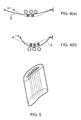
- Figures 4(a) and 4(b) show how the movement of the web 5 in straightening (4a) or further buckling (4b) applies a force to the filler on both faces of the web, amplifying the damping effect.
- Minus signs indicate tensile strain, plus signs indicate compressive strain.
- the load-carrying capability is not compromised since shear loadings (due to relative motion of the panels) are taken by the tensile members.
- the compressive members will tend not to buckle, because of micro-inertial structural effects and also the significant strain-rate strengthening of the viscoelastic filler (a characteristic of polymer materials).
- viscoelastic damping medium e.g. epoxy, polyurethane, etc. or a syntactic mixture (incorporating glass, polymer, ceramic, metallic, etc. solid or hollow microspheres).
- the pre-buckled linecore can be manufactured by using a similar process to the current SPF/DB linecore blade manufacturing route.
- the key difference here is to over-blow the blade to something over the nominal blade thickness and then compress the panels, as shown in Figure 1 .
- the compression could be performed in a second mould, for instance.
- twisting the blade or shearing the panels relative to one another will result in tensile members remaining straight and compressive members becoming buckled, as in Figure 2 .
- the structure allows the blade to deform before the reinforcing membranes are taut, which maximises the strain passed into the viscoelastic filler material; the damping is thus maximised without compromising the other structural and integrity requirements.
- the invention thus describes use of the buckling behaviour of a compressive member to amplify the strain passed into a strain-based damping medium where a structure is in place to provide through-thickness reinforcement.
Landscapes
- Engineering & Computer Science (AREA)
- Mechanical Engineering (AREA)
- General Engineering & Computer Science (AREA)
- Physics & Mathematics (AREA)
- Fluid Mechanics (AREA)
- Architecture (AREA)
- Vibration Dampers (AREA)
- Vibration Prevention Devices (AREA)
- Turbine Rotor Nozzle Sealing (AREA)
Abstract
Description
- The invention relates in particular to blades for turbine engines, though it may be used for other components that need to be lightweight but also capable of taking up considerable static and dynamic loads.
- Metal blades for larger engines tend to be hollow, to reduce weight and materials costs. The cavity is filled with a viscoelastic polymer to damp vibrations in the blade. While the strength of such a blade is adequate for the stresses arising in operation, for additional resistance to impact of foreign objects such as birds some reinforcement is necessary.
- A successful design for strengthening such blades is the diffusion-bonded superplastic-formed (DB/SPF) technique. In this method, two panels forming the outer skin of the blade are placed one on top of the other with a patterned sheet between them that defines the bonding points or lines; these lines generally run longitudinally, perhaps 30 of them in a blade of width 40cm. The assembly is then heated to bond the panels at these desired locations and inflated to form a blade shape. The blade is usually twisted at the same time. At the high temperatures used, the bonded parts pull material from both panels as the structure expands, to form the reinforcing webs; the webs stretch between the panels at an angle of about 45° (to the blade thickness direction). This process is widely used and is described, for instance, in Rolls-Royce's earlier applications
GB 2269555 GB 2306353 WO 95/29787 - Such a blade is also known as a linecore blade. The structural reinforcement is in the form of elongate webs running the length of the blade, the webs being alternately inclined to the blade thickness direction so as to form a kind of corrugation. This is illustrated in
US 5581882 (Fowler et al , Rolls Royce) andUS 5240376 (McDonnell Douglas ). - A disadvantage of the SPF/DB technique is that the blade, as well as being stronger, is also more rigid. This means that, if the cavity or cavities are then filled with damping material, the damping effect is largely lost because the blade will not flex enough for a given stress. There exist various methods of reinforcing damping materials so that they better withstand other structural loads. However, such methods also tend to reduce strain in the damping medium and therefore reduce or negate the damping effect. The invention aims to tackle this problem.
- This invention can use a similar construction to a conventional linecore but makes modifications to the structure; manufacturing methods are also contemplated. According to one aspect of the invention there is provided a blade for a turbine engine, the blade having a hollow skin and internal reinforcement in the form of webs extending between the two faces of the skin at an inclination to the plane of the blade, in which at least some of the webs are buckled, in the rest stage of the blade, so as to be capable of extension upon deformation of the blade. Preferably at least part of the remaining space is occupied with a visco-elastic filler, so that when an adjacent web straightens or extends, or indeed is further buckled or compressed, work is done on the filler to damp movement. Preferably all the webs are buckled, so that the blade can deform at a low modulus in any direction.
- In a second aspect the invention provides a method for making such a blade, in which a skin formed of two overlaid panels is inflated, forming webs between the panels by virtue of local bonding, and the pressure is then released or the panels are compressed or displaced with respect to each other so as to buckle at least some of the webs.
- The invention is preferably applied to a hollow DB/SPF fan blade. Typically such blades are made of titanium alloys, and the forming/bonding process is done at 800-900°C.
- The webs preferably extend largely longitudinally along the blade, from root to tip. They can all be buckled in the same direction across the width of the blade, or in alternate directions, or randomly. The buckling should be at least 0.5mm or so off the plane; for a typical blade thickness of a few centimetres the thickness will normally decrease from perhaps 40-50 mm at the root to 10-15 mm at the tip.
- The efficiency of a strain-based damper is dependent on the strain energy in the damping material relative to the total strain energy in the structure; consequently, damping can be maximised if the strain in the damping material is maximised.
- For a better understanding of the invention, embodiments of it will now be described, by way of example, with reference to the accompanying drawings, in which:
-
Figure 1 shows a section through an embodiment at rest, showing the buckling; -
Figure 2 shows a second embodiment; -
Figure 3 diagrammatically shows various stages in the function of the blade; -
Figure 4 shows how the movement of the web amplifies the damping effects; and -
Figure 5 shows a blade to which the invention can be applied. -
Figure 1 schematically shows a section through a fan blade, having an outer skin made of two panels, apressure side panel 1 and asuction side panel 3. Generally longitudinal reinforcement webs ormembranes 5 extend between the panels in the manner of a corrugation. The section is across the blade, showing the webs inclined at an angle of about 45° to the thickness of the blade. The blade is made by the SPF/DB process, the webs being formed as the blade is inflated at a high temperature at which the metal is easily deformable and quite viscous. The modification envisaged by the invention is to pre-buckle the web of the core structure so that thewebs 5 are not flat (planar) but somewhat curved. This is achieved by deforming, preferably compressing, the blade after inflation, as will be described. Hence thewebs 5 are not quite flat, as in the prior art, but deformed by maybe 1-5 % from the plane - say, 0.5 mm for a chord of 40-50 mm. - Thus when a load is applied to the blade at low strain rates (either radial bending or torsion around the stacking axis during vibration), the webs deform laterally (elastic buckling) and strain the visco-elastic material local to the web.
-
Figure 2 shows a different embodiment in which the twopanels web 5a is now taut (flat), so that the damping is less effective for displacements in the same direction as the deformation, but the other 5b is buckled, and so there is good damping at least for reverse displacements. - The principle of strain amplification is illustrated in
Figure 3 . This straining effect is in addition to any strain that might occur due to compression or shear of one panel relative to the other; consequently the strain energy in the damping filler is maximised.Figure 3(a) shows the same section asFigures 1 and 2 , with the blade undeformed.Figure 3(b) (which shows only theweb 5, for ease of understanding) shows a shear load of theupper panel 1 to the left; theweb 5 straightens.Figure 3(c) shows compressive load on the blade, causing the web to buckle further, andFigure 3(d) a tensile load, again straightening the web. -
Figures 4(a) and 4(b) show how the movement of theweb 5 in straightening (4a) or further buckling (4b) applies a force to the filler on both faces of the web, amplifying the damping effect. Minus signs indicate tensile strain, plus signs indicate compressive strain. - During impact, the load-carrying capability is not compromised since shear loadings (due to relative motion of the panels) are taken by the tensile members. The compressive members will tend not to buckle, because of micro-inertial structural effects and also the significant strain-rate strengthening of the viscoelastic filler (a characteristic of polymer materials).
- Any type of viscoelastic damping medium is suitable, e.g. epoxy, polyurethane, etc. or a syntactic mixture (incorporating glass, polymer, ceramic, metallic, etc. solid or hollow microspheres).
- The pre-buckled linecore can be manufactured by using a similar process to the current SPF/DB linecore blade manufacturing route. The key difference here is to over-blow the blade to something over the nominal blade thickness and then compress the panels, as shown in
Figure 1 . The compression could be performed in a second mould, for instance. - Alternatively, twisting the blade or shearing the panels relative to one another will result in tensile members remaining straight and compressive members becoming buckled, as in
Figure 2 . - The structure allows the blade to deform before the reinforcing membranes are taut, which maximises the strain passed into the viscoelastic filler material; the damping is thus maximised without compromising the other structural and integrity requirements.
- The invention thus describes use of the buckling behaviour of a compressive member to amplify the strain passed into a strain-based damping medium where a structure is in place to provide through-thickness reinforcement.
Claims (9)
- A blade for a machine such as a turbine engine, the blade having a hollow skin formed from two panels (1, 3) and internal reinforcement in the form of webs (5) extending between the two panels so as to reinforce the blade, in which at least some of the webs are buckled so as to be capable of extension upon deformation of the blade.
- A blade according to claim 1, in which the remaining space between the webs is occupied with a visco-elastic filler (7).
- A blade according to claim 1 or 2, in which the webs extend longitudinally with respect to the blade.
- A blade according to any preceding claim, in which the buckling is about 1-5% out of the plane of the webs.
- A blade according to any preceding claim, in which the blade is made of a titanium alloy.
- A turbine engine having turbine blades according to any preceding claim.
- A method for making a hollow blade, in which an initial empty skin made of two panels (1,3) attached to each other at selected points is inflated, forming webs (5) extending at an angle to the thickness of the blade, and the panels are then displaced in order to buckle the webs out of a planar shape.
- A method according to claim 7, in which the displacement of the panels is carried out in the thickness direction by releasing the pressure at the end of the inflation process, or by separately compressing the panels after formation of the blade.
- A method according to claim 7, in which the displacement is performed in the plane of the blade, by moving or twisting the panels with respect to each other.
Applications Claiming Priority (1)
| Application Number | Priority Date | Filing Date | Title |
|---|---|---|---|
| GBGB0917229.7A GB0917229D0 (en) | 2009-10-02 | 2009-10-02 | Hollow turbine blade |
Publications (3)
| Publication Number | Publication Date |
|---|---|
| EP2305953A2 true EP2305953A2 (en) | 2011-04-06 |
| EP2305953A3 EP2305953A3 (en) | 2014-05-14 |
| EP2305953B1 EP2305953B1 (en) | 2017-12-20 |
Family
ID=41393710
Family Applications (1)
| Application Number | Title | Priority Date | Filing Date |
|---|---|---|---|
| EP10174257.5A Not-in-force EP2305953B1 (en) | 2009-10-02 | 2010-08-27 | Hollow turbine blade |
Country Status (3)
| Country | Link |
|---|---|
| US (1) | US8444390B2 (en) |
| EP (1) | EP2305953B1 (en) |
| GB (1) | GB0917229D0 (en) |
Cited By (2)
| Publication number | Priority date | Publication date | Assignee | Title |
|---|---|---|---|---|
| EP3260659A1 (en) * | 2016-06-22 | 2017-12-27 | United Technologies Corporation | Fan blade filler |
| CN111604645A (en) * | 2020-05-23 | 2020-09-01 | 北京普惠三航科技有限公司 | Aircraft engine intake pipe forming method |
Families Citing this family (4)
| Publication number | Priority date | Publication date | Assignee | Title |
|---|---|---|---|---|
| US8763360B2 (en) | 2011-11-03 | 2014-07-01 | United Technologies Corporation | Hollow fan blade tuning using distinct filler materials |
| US10301948B2 (en) * | 2013-03-14 | 2019-05-28 | United Technologies Corporation | Fan blade damping device |
| US10801329B2 (en) | 2017-11-17 | 2020-10-13 | General Electric Company | Vibration-damping components, gas turbine engine and method of forming such components |
| US11242756B2 (en) * | 2020-05-04 | 2022-02-08 | General Electric Company | Damping coating with a constraint layer |
Citations (5)
| Publication number | Priority date | Publication date | Assignee | Title |
|---|---|---|---|---|
| US5240376A (en) | 1991-07-31 | 1993-08-31 | Mcdonnell Douglas Corporation | SPF/DB hollow core fan blade |
| GB2269555A (en) | 1992-08-14 | 1994-02-16 | Rolls Royce Plc | A method of manufacturing an article by superplastic forming and diffusion bonding |
| WO1995029787A1 (en) | 1994-04-29 | 1995-11-09 | United Technologies Corporation | Hollow fan blade fabrication |
| US5581882A (en) | 1994-06-07 | 1996-12-10 | Rolls-Royce Plc | Method of manufacturing an article by superplastic forming and diffusion bonding |
| GB2306353A (en) | 1995-10-28 | 1997-05-07 | Rolls Royce Plc | A method of manufacturing a blade |
Family Cites Families (9)
| Publication number | Priority date | Publication date | Assignee | Title |
|---|---|---|---|---|
| US4811890A (en) * | 1983-05-07 | 1989-03-14 | Rockwell International Corporation | Method of eliminating core distortion in diffusion bonded and uperplastically formed structures |
| US4882823A (en) * | 1988-01-27 | 1989-11-28 | Ontario Technologies Corp. | Superplastic forming diffusion bonding process |
| US5439354A (en) * | 1993-06-15 | 1995-08-08 | General Electric Company | Hollow airfoil impact resistance improvement |
| US5513791A (en) * | 1994-03-28 | 1996-05-07 | General Electric Company | Strippable mask patterning of stop-off for diffusion bond processing |
| US6039542A (en) * | 1997-12-24 | 2000-03-21 | General Electric Company | Panel damped hybrid blade |
| GB2400055B (en) * | 2003-03-29 | 2006-01-11 | Rolls Royce Plc | A hollow component with internal damping |
| FR2853572B1 (en) * | 2003-04-10 | 2005-05-27 | Snecma Moteurs | METHOD FOR MANUFACTURING A HOLLOW MECHANICAL WELDING-DIFFUSION MECHANICAL PIECE AND SUPERPLASTIC FORMING |
| GB2450934B (en) * | 2007-07-13 | 2009-10-07 | Rolls Royce Plc | A Component with a damping filler |
| GB2450935B (en) * | 2007-07-13 | 2009-06-03 | Rolls Royce Plc | Component with internal damping |
-
2009
- 2009-10-02 GB GBGB0917229.7A patent/GB0917229D0/en not_active Ceased
-
2010
- 2010-08-27 EP EP10174257.5A patent/EP2305953B1/en not_active Not-in-force
- 2010-08-27 US US12/870,115 patent/US8444390B2/en not_active Expired - Fee Related
Patent Citations (5)
| Publication number | Priority date | Publication date | Assignee | Title |
|---|---|---|---|---|
| US5240376A (en) | 1991-07-31 | 1993-08-31 | Mcdonnell Douglas Corporation | SPF/DB hollow core fan blade |
| GB2269555A (en) | 1992-08-14 | 1994-02-16 | Rolls Royce Plc | A method of manufacturing an article by superplastic forming and diffusion bonding |
| WO1995029787A1 (en) | 1994-04-29 | 1995-11-09 | United Technologies Corporation | Hollow fan blade fabrication |
| US5581882A (en) | 1994-06-07 | 1996-12-10 | Rolls-Royce Plc | Method of manufacturing an article by superplastic forming and diffusion bonding |
| GB2306353A (en) | 1995-10-28 | 1997-05-07 | Rolls Royce Plc | A method of manufacturing a blade |
Cited By (2)
| Publication number | Priority date | Publication date | Assignee | Title |
|---|---|---|---|---|
| EP3260659A1 (en) * | 2016-06-22 | 2017-12-27 | United Technologies Corporation | Fan blade filler |
| CN111604645A (en) * | 2020-05-23 | 2020-09-01 | 北京普惠三航科技有限公司 | Aircraft engine intake pipe forming method |
Also Published As
| Publication number | Publication date |
|---|---|
| EP2305953A3 (en) | 2014-05-14 |
| US20110081249A1 (en) | 2011-04-07 |
| EP2305953B1 (en) | 2017-12-20 |
| US8444390B2 (en) | 2013-05-21 |
| GB0917229D0 (en) | 2009-11-18 |
Similar Documents
| Publication | Publication Date | Title |
|---|---|---|
| US8444390B2 (en) | Hollow turbine blade | |
| US8241004B2 (en) | Component structure | |
| EP2014388B1 (en) | Aerofoil for a turbomachine with a damping filler and method of manufacturing thereof | |
| EP3318402A1 (en) | Energy absorbing beam and sandwich panel structure | |
| EP2108083B1 (en) | Reinforced blade for wind turbine | |
| CN101646865B (en) | Reinforced aerodynamic profile | |
| JP4556046B2 (en) | Aircraft wing and flap, and wing shape control method | |
| CN102884309B (en) | The airfoil body strengthened | |
| US20150144256A1 (en) | Part comprising a structure and a shape memory alloy element | |
| US20080152858A1 (en) | Hybrid fan blade and method for its manufacture | |
| CN101611225A (en) | Reinforced blades for wind turbines | |
| CN102317620A (en) | A rotor blade for a wind turbine and a method for making the same | |
| US9970357B2 (en) | Superelastic fluid conduit for a gas turbine engine | |
| JP4420830B2 (en) | Shock absorbing member | |
| EP3526468B1 (en) | Wind tubine blade with variable deflection-dependent stiffness | |
| Hwang et al. | Development of a bendable pyramidal kagome structure and its structural characteristics | |
| JP5113734B2 (en) | Flex beam cross section determination method and flex beam | |
| US20180171876A1 (en) | Mount structure | |
| EP3228819B1 (en) | Blade comprising cmc layers | |
| GB2536707A (en) | Turbomachinery blade | |
| EP3680091B1 (en) | Joint structure | |
| CN113053472A (en) | PVA fiber cement-based composite material laminated plate and curvature ductility calculation method | |
| JP3938718B2 (en) | Reinforced concrete beam structure | |
| JP7477381B2 (en) | Timber joints, timber joint structures and surface-bearing walls | |
| KR200298950Y1 (en) | Concrete structure with fiber reinforced plastic bar as reinforcement thereof |
Legal Events
| Date | Code | Title | Description |
|---|---|---|---|
| PUAI | Public reference made under article 153(3) epc to a published international application that has entered the european phase |
Free format text: ORIGINAL CODE: 0009012 |
|
| AK | Designated contracting states |
Kind code of ref document: A2 Designated state(s): AL AT BE BG CH CY CZ DE DK EE ES FI FR GB GR HR HU IE IS IT LI LT LU LV MC MK MT NL NO PL PT RO SE SI SK SM TR |
|
| AX | Request for extension of the european patent |
Extension state: BA ME RS |
|
| PUAL | Search report despatched |
Free format text: ORIGINAL CODE: 0009013 |
|
| AK | Designated contracting states |
Kind code of ref document: A3 Designated state(s): AL AT BE BG CH CY CZ DE DK EE ES FI FR GB GR HR HU IE IS IT LI LT LU LV MC MK MT NL NO PL PT RO SE SI SK SM TR |
|
| AX | Request for extension of the european patent |
Extension state: BA ME RS |
|
| RIC1 | Information provided on ipc code assigned before grant |
Ipc: F01D 5/16 20060101ALI20140409BHEP Ipc: F01D 5/14 20060101AFI20140409BHEP Ipc: F01D 5/18 20060101ALI20140409BHEP Ipc: B21D 26/055 20110101ALI20140409BHEP Ipc: B21D 53/78 20060101ALI20140409BHEP |
|
| 17P | Request for examination filed |
Effective date: 20141112 |
|
| RBV | Designated contracting states (corrected) |
Designated state(s): AL AT BE BG CH CY CZ DE DK EE ES FI FR GB GR HR HU IE IS IT LI LT LU LV MC MK MT NL NO PL PT RO SE SI SK SM TR |
|
| RAP1 | Party data changed (applicant data changed or rights of an application transferred) |
Owner name: ROLLS-ROYCE PLC |
|
| GRAP | Despatch of communication of intention to grant a patent |
Free format text: ORIGINAL CODE: EPIDOSNIGR1 |
|
| STAA | Information on the status of an ep patent application or granted ep patent |
Free format text: STATUS: GRANT OF PATENT IS INTENDED |
|
| GRAS | Grant fee paid |
Free format text: ORIGINAL CODE: EPIDOSNIGR3 |
|
| GRAA | (expected) grant |
Free format text: ORIGINAL CODE: 0009210 |
|
| STAA | Information on the status of an ep patent application or granted ep patent |
Free format text: STATUS: THE PATENT HAS BEEN GRANTED |
|
| INTG | Intention to grant announced |
Effective date: 20171026 |
|
| AK | Designated contracting states |
Kind code of ref document: B1 Designated state(s): AL AT BE BG CH CY CZ DE DK EE ES FI FR GB GR HR HU IE IS IT LI LT LU LV MC MK MT NL NO PL PT RO SE SI SK SM TR |
|
| REG | Reference to a national code |
Ref country code: GB Ref legal event code: FG4D |
|
| REG | Reference to a national code |
Ref country code: CH Ref legal event code: EP |
|
| REG | Reference to a national code |
Ref country code: IE Ref legal event code: FG4D |
|
| REG | Reference to a national code |
Ref country code: AT Ref legal event code: REF Ref document number: 956585 Country of ref document: AT Kind code of ref document: T Effective date: 20180115 |
|
| REG | Reference to a national code |
Ref country code: DE Ref legal event code: R096 Ref document number: 602010047445 Country of ref document: DE |
|
| REG | Reference to a national code |
Ref country code: NL Ref legal event code: MP Effective date: 20171220 |
|
| PG25 | Lapsed in a contracting state [announced via postgrant information from national office to epo] |
Ref country code: LT Free format text: LAPSE BECAUSE OF FAILURE TO SUBMIT A TRANSLATION OF THE DESCRIPTION OR TO PAY THE FEE WITHIN THE PRESCRIBED TIME-LIMIT Effective date: 20171220 Ref country code: SE Free format text: LAPSE BECAUSE OF FAILURE TO SUBMIT A TRANSLATION OF THE DESCRIPTION OR TO PAY THE FEE WITHIN THE PRESCRIBED TIME-LIMIT Effective date: 20171220 Ref country code: NO Free format text: LAPSE BECAUSE OF FAILURE TO SUBMIT A TRANSLATION OF THE DESCRIPTION OR TO PAY THE FEE WITHIN THE PRESCRIBED TIME-LIMIT Effective date: 20180320 Ref country code: FI Free format text: LAPSE BECAUSE OF FAILURE TO SUBMIT A TRANSLATION OF THE DESCRIPTION OR TO PAY THE FEE WITHIN THE PRESCRIBED TIME-LIMIT Effective date: 20171220 |
|
| REG | Reference to a national code |
Ref country code: LT Ref legal event code: MG4D |
|
| REG | Reference to a national code |
Ref country code: AT Ref legal event code: MK05 Ref document number: 956585 Country of ref document: AT Kind code of ref document: T Effective date: 20171220 |
|
| PG25 | Lapsed in a contracting state [announced via postgrant information from national office to epo] |
Ref country code: GR Free format text: LAPSE BECAUSE OF FAILURE TO SUBMIT A TRANSLATION OF THE DESCRIPTION OR TO PAY THE FEE WITHIN THE PRESCRIBED TIME-LIMIT Effective date: 20180321 Ref country code: LV Free format text: LAPSE BECAUSE OF FAILURE TO SUBMIT A TRANSLATION OF THE DESCRIPTION OR TO PAY THE FEE WITHIN THE PRESCRIBED TIME-LIMIT Effective date: 20171220 Ref country code: HR Free format text: LAPSE BECAUSE OF FAILURE TO SUBMIT A TRANSLATION OF THE DESCRIPTION OR TO PAY THE FEE WITHIN THE PRESCRIBED TIME-LIMIT Effective date: 20171220 Ref country code: BG Free format text: LAPSE BECAUSE OF FAILURE TO SUBMIT A TRANSLATION OF THE DESCRIPTION OR TO PAY THE FEE WITHIN THE PRESCRIBED TIME-LIMIT Effective date: 20180320 |
|
| PG25 | Lapsed in a contracting state [announced via postgrant information from national office to epo] |
Ref country code: NL Free format text: LAPSE BECAUSE OF FAILURE TO SUBMIT A TRANSLATION OF THE DESCRIPTION OR TO PAY THE FEE WITHIN THE PRESCRIBED TIME-LIMIT Effective date: 20171220 |
|
| PG25 | Lapsed in a contracting state [announced via postgrant information from national office to epo] |
Ref country code: CY Free format text: LAPSE BECAUSE OF FAILURE TO SUBMIT A TRANSLATION OF THE DESCRIPTION OR TO PAY THE FEE WITHIN THE PRESCRIBED TIME-LIMIT Effective date: 20171220 Ref country code: CZ Free format text: LAPSE BECAUSE OF FAILURE TO SUBMIT A TRANSLATION OF THE DESCRIPTION OR TO PAY THE FEE WITHIN THE PRESCRIBED TIME-LIMIT Effective date: 20171220 Ref country code: ES Free format text: LAPSE BECAUSE OF FAILURE TO SUBMIT A TRANSLATION OF THE DESCRIPTION OR TO PAY THE FEE WITHIN THE PRESCRIBED TIME-LIMIT Effective date: 20171220 Ref country code: SK Free format text: LAPSE BECAUSE OF FAILURE TO SUBMIT A TRANSLATION OF THE DESCRIPTION OR TO PAY THE FEE WITHIN THE PRESCRIBED TIME-LIMIT Effective date: 20171220 Ref country code: EE Free format text: LAPSE BECAUSE OF FAILURE TO SUBMIT A TRANSLATION OF THE DESCRIPTION OR TO PAY THE FEE WITHIN THE PRESCRIBED TIME-LIMIT Effective date: 20171220 |
|
| REG | Reference to a national code |
Ref country code: FR Ref legal event code: PLFP Year of fee payment: 9 |
|
| PG25 | Lapsed in a contracting state [announced via postgrant information from national office to epo] |
Ref country code: AT Free format text: LAPSE BECAUSE OF FAILURE TO SUBMIT A TRANSLATION OF THE DESCRIPTION OR TO PAY THE FEE WITHIN THE PRESCRIBED TIME-LIMIT Effective date: 20171220 Ref country code: PL Free format text: LAPSE BECAUSE OF FAILURE TO SUBMIT A TRANSLATION OF THE DESCRIPTION OR TO PAY THE FEE WITHIN THE PRESCRIBED TIME-LIMIT Effective date: 20171220 Ref country code: RO Free format text: LAPSE BECAUSE OF FAILURE TO SUBMIT A TRANSLATION OF THE DESCRIPTION OR TO PAY THE FEE WITHIN THE PRESCRIBED TIME-LIMIT Effective date: 20171220 Ref country code: IS Free format text: LAPSE BECAUSE OF FAILURE TO SUBMIT A TRANSLATION OF THE DESCRIPTION OR TO PAY THE FEE WITHIN THE PRESCRIBED TIME-LIMIT Effective date: 20180420 Ref country code: IT Free format text: LAPSE BECAUSE OF FAILURE TO SUBMIT A TRANSLATION OF THE DESCRIPTION OR TO PAY THE FEE WITHIN THE PRESCRIBED TIME-LIMIT Effective date: 20171220 Ref country code: SM Free format text: LAPSE BECAUSE OF FAILURE TO SUBMIT A TRANSLATION OF THE DESCRIPTION OR TO PAY THE FEE WITHIN THE PRESCRIBED TIME-LIMIT Effective date: 20171220 |
|
| REG | Reference to a national code |
Ref country code: DE Ref legal event code: R097 Ref document number: 602010047445 Country of ref document: DE |
|
| PLBE | No opposition filed within time limit |
Free format text: ORIGINAL CODE: 0009261 |
|
| STAA | Information on the status of an ep patent application or granted ep patent |
Free format text: STATUS: NO OPPOSITION FILED WITHIN TIME LIMIT |
|
| 26N | No opposition filed |
Effective date: 20180921 |
|
| PG25 | Lapsed in a contracting state [announced via postgrant information from national office to epo] |
Ref country code: DK Free format text: LAPSE BECAUSE OF FAILURE TO SUBMIT A TRANSLATION OF THE DESCRIPTION OR TO PAY THE FEE WITHIN THE PRESCRIBED TIME-LIMIT Effective date: 20171220 |
|
| PG25 | Lapsed in a contracting state [announced via postgrant information from national office to epo] |
Ref country code: SI Free format text: LAPSE BECAUSE OF FAILURE TO SUBMIT A TRANSLATION OF THE DESCRIPTION OR TO PAY THE FEE WITHIN THE PRESCRIBED TIME-LIMIT Effective date: 20171220 |
|
| PG25 | Lapsed in a contracting state [announced via postgrant information from national office to epo] |
Ref country code: MC Free format text: LAPSE BECAUSE OF FAILURE TO SUBMIT A TRANSLATION OF THE DESCRIPTION OR TO PAY THE FEE WITHIN THE PRESCRIBED TIME-LIMIT Effective date: 20171220 |
|
| REG | Reference to a national code |
Ref country code: CH Ref legal event code: PL |
|
| PG25 | Lapsed in a contracting state [announced via postgrant information from national office to epo] |
Ref country code: LU Free format text: LAPSE BECAUSE OF NON-PAYMENT OF DUE FEES Effective date: 20180827 Ref country code: CH Free format text: LAPSE BECAUSE OF NON-PAYMENT OF DUE FEES Effective date: 20180831 Ref country code: LI Free format text: LAPSE BECAUSE OF NON-PAYMENT OF DUE FEES Effective date: 20180831 |
|
| REG | Reference to a national code |
Ref country code: BE Ref legal event code: MM Effective date: 20180831 |
|
| PG25 | Lapsed in a contracting state [announced via postgrant information from national office to epo] |
Ref country code: BE Free format text: LAPSE BECAUSE OF NON-PAYMENT OF DUE FEES Effective date: 20180831 |
|
| PGFP | Annual fee paid to national office [announced via postgrant information from national office to epo] |
Ref country code: FR Payment date: 20190826 Year of fee payment: 10 Ref country code: DE Payment date: 20190828 Year of fee payment: 10 |
|
| PGFP | Annual fee paid to national office [announced via postgrant information from national office to epo] |
Ref country code: GB Payment date: 20190827 Year of fee payment: 10 |
|
| PG25 | Lapsed in a contracting state [announced via postgrant information from national office to epo] |
Ref country code: MT Free format text: LAPSE BECAUSE OF NON-PAYMENT OF DUE FEES Effective date: 20180827 |
|
| PG25 | Lapsed in a contracting state [announced via postgrant information from national office to epo] |
Ref country code: TR Free format text: LAPSE BECAUSE OF FAILURE TO SUBMIT A TRANSLATION OF THE DESCRIPTION OR TO PAY THE FEE WITHIN THE PRESCRIBED TIME-LIMIT Effective date: 20171220 |
|
| PG25 | Lapsed in a contracting state [announced via postgrant information from national office to epo] |
Ref country code: PT Free format text: LAPSE BECAUSE OF FAILURE TO SUBMIT A TRANSLATION OF THE DESCRIPTION OR TO PAY THE FEE WITHIN THE PRESCRIBED TIME-LIMIT Effective date: 20171220 Ref country code: HU Free format text: LAPSE BECAUSE OF FAILURE TO SUBMIT A TRANSLATION OF THE DESCRIPTION OR TO PAY THE FEE WITHIN THE PRESCRIBED TIME-LIMIT; INVALID AB INITIO Effective date: 20100827 |
|
| PG25 | Lapsed in a contracting state [announced via postgrant information from national office to epo] |
Ref country code: MK Free format text: LAPSE BECAUSE OF NON-PAYMENT OF DUE FEES Effective date: 20171220 Ref country code: IE Free format text: LAPSE BECAUSE OF NON-PAYMENT OF DUE FEES Effective date: 20180827 |
|
| PG25 | Lapsed in a contracting state [announced via postgrant information from national office to epo] |
Ref country code: AL Free format text: LAPSE BECAUSE OF FAILURE TO SUBMIT A TRANSLATION OF THE DESCRIPTION OR TO PAY THE FEE WITHIN THE PRESCRIBED TIME-LIMIT Effective date: 20171220 |
|
| REG | Reference to a national code |
Ref country code: DE Ref legal event code: R119 Ref document number: 602010047445 Country of ref document: DE |
|
| GBPC | Gb: european patent ceased through non-payment of renewal fee |
Effective date: 20200827 |
|
| PG25 | Lapsed in a contracting state [announced via postgrant information from national office to epo] |
Ref country code: DE Free format text: LAPSE BECAUSE OF NON-PAYMENT OF DUE FEES Effective date: 20210302 Ref country code: FR Free format text: LAPSE BECAUSE OF NON-PAYMENT OF DUE FEES Effective date: 20200831 |
|
| PG25 | Lapsed in a contracting state [announced via postgrant information from national office to epo] |
Ref country code: GB Free format text: LAPSE BECAUSE OF NON-PAYMENT OF DUE FEES Effective date: 20200827 |