EP2305914A2 - An arrangement for mounting a roof window - Google Patents
An arrangement for mounting a roof window Download PDFInfo
- Publication number
- EP2305914A2 EP2305914A2 EP10176970A EP10176970A EP2305914A2 EP 2305914 A2 EP2305914 A2 EP 2305914A2 EP 10176970 A EP10176970 A EP 10176970A EP 10176970 A EP10176970 A EP 10176970A EP 2305914 A2 EP2305914 A2 EP 2305914A2
- Authority
- EP
- European Patent Office
- Prior art keywords
- roof window
- roof
- arrangement
- mounting
- installing
- Prior art date
- Legal status (The legal status is an assumption and is not a legal conclusion. Google has not performed a legal analysis and makes no representation as to the accuracy of the status listed.)
- Withdrawn
Links
Images


Classifications
-
- E—FIXED CONSTRUCTIONS
- E04—BUILDING
- E04D—ROOF COVERINGS; SKY-LIGHTS; GUTTERS; ROOF-WORKING TOOLS
- E04D13/00—Special arrangements or devices in connection with roof coverings; Protection against birds; Roof drainage; Sky-lights
- E04D13/03—Sky-lights; Domes; Ventilating sky-lights
- E04D13/0305—Supports or connecting means for sky-lights of flat or domed shape
- E04D13/031—Supports or connecting means for sky-lights of flat or domed shape characterised by a frame for connection to an inclined roof
Landscapes
- Engineering & Computer Science (AREA)
- Architecture (AREA)
- Civil Engineering (AREA)
- Structural Engineering (AREA)
- Window Of Vehicle (AREA)
- Securing Of Glass Panes Or The Like (AREA)
- Roof Covering Using Slabs Or Stiff Sheets (AREA)
Abstract
Description
- The present invention relates to an arrangement for mounting a roof window and in particular to an arrangement for mounting a roof window to accommodate different types of tiles and slates and mounting roof windows at variable depths relative to the main plane of the roof.
- Roof windows are often mounted on an inclined surface of a roof to provide skylights into the working and living space of buildings. An opening must be made in the roof to allow a roof window frame to be structurally mounted onto the roof rafters or support structures associated with the rafters. A difficult aspect for the person installing a roof window centers around calculating the distance the roof window frame should protrude out of the inclined surface of the roof in order to sit in flush alignment with the type of roof covering material to be used on the job. Additionally, in view of various types of battens and other roof structure components, an installer is often required to adjust the depth of the roof window frame relative to the roof. When this position is accurately worked out, the installer still has to measure and locate mounting brackets on the frame of the roof window to ensure the roof window protrudes by the required distance. All of this work has to be done on the roof of a building taking into account the particular structural peculiarities of each job. A variety of roof covering materials are available with slates having a depth of 4, 5 or 6 mm requiring the roof window frame to be mounted at one depth relative to the roof. Slates having a depth of 7, 8, 9 or 10 mm and all tiles require the roof frame to be mounted at a second depth relative to the roof.
- Several roof window mounting arrangements have been developed to ease the burden on persons installing roof windows and to allow roof windows to be mounted at different positions/depths relative to the roof. The earliest technologies used mounting brackets with spikes spaced apart horizontally in use for engagement with vertically spaced apart longitudinal grooves cut into the side members of the roof window frame. The longitudinal grooves were spaced apart along the depth of the window frame to allow a range of locations for insertion of the spikes of the mounting brackets. This positional adjustment of the mounting brackets allowed the roof window to be set into the roof at variable depths. Further mounting arrangements provide longitudinal slots in the mounting bracket allowing the installer to adjust the position of the mounting bracket by sliding the bracket along the fixing members via the slot. Other technologies provide a mounting bracket with longitudinal markings having a graduated scale. This allows the installer to select the position that the mounting bracket is fixed to the roof window by screwing fixing members into the mounting bracket at the required position of the graduated scale.
- It is an object of the present invention to provide a novel arrangement to allow roof windows to be mounted to the roof at various depths to accommodate alignment between the roof window and the roof to accommodate different types of roof covering material for example.
- Accordingly, the present invention provides an arrangement for installing a roof window at variable depths relative to the planar surface of the roof structure comprising a roof window having a roof window frame comprising two side members, a top member and a bottom member, at least two mounting brackets and variable depth guide means operable between the roof window frame and each mounting bracket, the variable depth guide means comprising at least two spaced apart mounting means and one locating means or at least two spaced apart locating means and one mounting means with the at least two spaced apart locating means having barrier means mounted therein.
- Preferably, the locating means are female members and the mounting means are male members.
- In one embodiment of variable depth guide means, the at least two spaced apart locating means are recesses having barrier means removably mounted therein and the mounting means is formed for insertion into the locating means.
- Advantageously, the mounting bracket can not be mounted on the roof window frame until a positive decision has been made regarding which of the two spaced apart mounting means should be removed or which of the barrier means should be removed from which female member. In this way the person installing the roof window is forced into positively discriminating between at least two mounting means or at least two barrier means and so a selection must be made which will determine the depth at which the roof window is mounted onto the roof. This decision is determined by the depth of roof covering material used on the roof in one situation and can be determined by the type of battens used or other considerations which effect the depth that the roof window is to be mounted into the roof.
- In one embodiment, the locating means is provided on the roof window frame and the mounting means is provided on the mounting bracket.
- In a second embodiment, the locating means is provided on the mounting bracket and the mounting means is provided on the roof window frame.
- In a third embodiment, the locating means is provided on a member fixable to the roof window frame and the mounting means is provided on the mounting bracket.
- In a fourth embodiment, the mounting means is provided on a member fixable to the roof window frame and the locating means is provided on the mounting bracket.
- Ideally, the mounting bracket has a roof window frame engaging portion for contacting the roof window frame and a roof engaging portion for contacting the roof.
- Preferably, the roof window frame engaging portion has mounting means protruding there from for insertion into a recess when a barrier member has been removed.
- Ideally, at least one pair of spaced apart recesses having a removable barrier member in each recess is provided on mutually opposing window frame components. Advantageously, the spaced apart recesses are provided on the external surfaces of the top, bottom and/or side members of the roof window frame.
- Preferably, at least one pair of spaced apart recesses having a removable barrier member in each recess is provided on each window frame component.
- Ideally, the pair of spaced apart recesses is provided by a pair of substantially parallel spaced apart longitudinal slots. It will of course be appreciated that the invention is in no way limited to recesses comprising longitudinal slots and that recesses of any shape or size can be used to accommodate the mounting means provided they engage with the mounting means to the degree required to carry out their intended purpose.
- Preferably, the recesses are spaced apart the required distance to ensure the roof window sits in substantial alignment with the roof or roof covering material.
- Ideally, the barrier members are provided with indicia means.
- Preferably, the indicia means comprise a pair of different coloured barrier members. Advantageously, the barrier members with different colours indicate which slot is to be used with which roof covering material. The different colours provide an instantly recognizable visual cue to the person installing the roof window.
- Alternatively, the recesses are provided with indicia means.
- Ideally, the two recesses have different lengths. Advantageously, the recesses with different lengths indicate which recess is to be used with which roof covering material. The different lengths of the recesses provide an instantly recognizable visual cue to the person installing the roof window.
- Alternatively, the mounting means are provided with indicia means. Advantageously, the indicia means indicate which mounting means is to be used with which roof covering material.
- Preferably, the recesses are spaced apart laterally along the width of the component members of the roof window frame.
- Ideally, the mounting means are spaced apart vertically in use.
- Ideally, two pairs of recesses are provided on each component member of the roof window frame.
- Preferably, one pair of recesses are provided on one component member proximal to one corner of the roof window and the other pair of recesses are provided on the same component member proximal another corner of the roof window frame.
- Preferably, fixing means are provided for fixing the mounting bracket to the roof window and the roof.
- Ideally, the mounting bracket comprises an angle bracket. Advantageously, the mounting bracket can be temporarily secured at a corner of the window frame for transport and storage.
- Preferably, the angle bracket has a pair of plate members defining apertures for receiving the fixing means such as wood screws.
- Ideally, the mounting bracket has stiffening means at the angle. Advantageously, the stiffening means increases the strength of the angle bracket.
- Preferably, the mounting bracket is punched from a metal sheet.
- Ideally, the mounting means comprise at least one tongue protruding from the roof window frame engaging portion of the mounting bracket.
- Preferably, the mounting means comprises a pair of tongues protruding from opposing corners of the roof window frame engaging portion of the mounting bracket.
- Ideally, the tongues bend away from the roof window frame engaging portion of the mounting bracket in the same direction as each other.
- Preferably, the barrier members are provided by disposable plug inserts.
- The invention will now be described with reference to the accompanying drawings which show by way of example only one embodiment of an arrangement for mounting a roof window to a roof in accordance with the invention. In the drawings:-
-
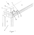
Figure 1 is a partial perspective view of an arrangement for mounting a roof window to a roof; -
Figure 2 is a partial perspective view of a first embodiment of a locating arrangement; -
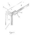
Figure 3 is a second partial perspective view of an arrangement for mounting a roof window to a roof; -
Figure 4 is a second partial perspective view of a first embodiment of a locating arrangement; -
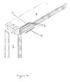
Figure 5 is a third partial perspective view of an arrangement for mounting a roof window to a roof; -
Figure 6 is a fourth partial perspective view of an arrangement for mounting a roof window to a roof in a transport/storage position. - Referring initially to
Figures 1 and2 , there is shown an arrangement indicated generally by the reference numeral 1 for mounting aroof window 2 to aroof 3, seeFig. 5 . The arrangement 1 is provided to accommodate installing aroof window 2 at variable depths relative to the planar surface of theroof 3. The arrangement 1 has aroof window 2 with a roof window frame 4 made up of components being twoside members 5, atop member 6 and a bottom member 7. The arrangement also has at least two mountingbrackets 8 and preferably four mountingbrackets 8. A variable depth guide arrangement is operable between the roof window frame 4 and each mountingbracket 8. The variable depth guide arrangement has locatingmembers 9 and mountingmembers 10, the locatingmembers 9 being provided by two spaced apart recesses 11 havingbarrier elements 14 removably mounted in the recesses 11. The mountingmembers 10 are formed for insertion into the locatingmembers 9. - Advantageously, the mounting
bracket 8 can not be mounted correctly on the roof window frame 4 until a positive decision has been made regarding whichbarrier element 14 should be removed from which recess 11. Alternatively, in the event that two spaced apart mounting members are provided on a mounting bracket and one locating member is provided on the window frame, the installer must make a decision as to which mounting member must be flattened or snapped off. In this way the person installing theroof window 2 is forced into positively discriminating between at least twobarrier elements 14 or mounting members and so a selection must be made which will determine the distance theroof window 2 is set into theroof 3. This decision is determined by the depth of roof covering material used on the roof. InFigures 1 and2 , thebarrier element 14 proximal to the edge of theroof window 2 has been removed to accommodate 7mm, 8mm, 9mm or 10mm slates or any tiles. - In the embodiment shown in the drawings, the locating
members 9 are provided on the roof window frame 4 and the mountingmembers 10 are provided on the mountingbracket 8. - In a second embodiment not shown in the drawings, the locating members are provided on the mounting bracket and the mounting members are provided on the roof window frame. In a third embodiment not shown in the drawings, the locating members are provided on a member fixable to the roof window frame such as a prefixed plate and the mounting members are provided on the mounting bracket. In a fourth embodiment not shown in the drawings, the mounting members are provided on a member fixable to the roof window frame such as a prefixed plate and the locating members are provided on the mounting bracket.
- Referring generally to
Figures 3 ,4 and5 of the drawings, the mountingbracket 8 has a roof window frame engaging portion 15 for contacting the roof window frame 4 and a roof engaging portion 16 for contacting theroof 3. The roof window frame engaging portion 15 has mountingmembers 10 protruding from it for insertion into a recess 11 when abarrier element 14 has been removed. One pair of spaced apart recesses 11 having aremovable barrier element 14 in each recess 11 is provided on mutually opposingwindow frame components 6 and 7. Advantageously, the spaced apart recesses 11 are provided on the external surfaces of the top 6, bottom 7 and/orside members 5 of the roof window frame 4. Infigures 3 and4 , thebarrier element 14 distal to the edge of the roof window frame 4 has been removed where 4mm, 5mm or 6mm slates are to be fitted to the roof. Whilst different depths of roof covering materials is provided as an example of a situation where a variable depth arrangement is required between the roof window frame and the roof, many other situations arise where the variable depth arrangement of the present invention can be used and the invention is in no way limited to use with different depths of roof covering tiles or slates. - In an alternative arrangement, one pair of spaced apart recesses 11 having a
removable barrier element 14 in each recess 11 is provided on eachwindow frame component Figure 4 . It will of course be appreciated that the invention is in no way limited to recesses 11 comprising longitudinal slots 21 and that recesses 11 of any shape or size can be used to accommodate the mountingmembers 10 provided they engage with the mountingmembers 10 to the degree required to carry out their intended purpose. The recesses 11 are spaced apart the required distance to ensure theroof window 2 sits in substantial alignment with the roof covering material. - The
barrier elements 14 are provided with an indicia arrangement and in the embodiment shown in the drawings, the indicia arrangement is provided by a pair ofbarrier elements 14 having a different colour. Advantageously, thebarrier elements 14 with different colours indicate which longitudinal slot 21 is to be used with which roof covering material. The different colours provide an instantly recognizable visual cue to the person installing theroof window 2. Alternatively, the recesses 11 are provided with an indicia arrangement where the two recesses 11 have different lengths. Advantageously, the recesses 11 with different lengths indicate which recess 11 is to be used with which roof covering material. The different lengths of the recesses 11 provide an instantly recognizable visual cue to the person installing the roof window. - The recesses 11 are spaced apart laterally along the width of the
component members component member roof 3. One pair of recesses 11 are provided on onecomponent member roof window 2 and the other pair of recesses 11 are provided on thesame component member - Fixing
members 31, seeFigure 6 are provided for fixing the mountingbracket 8 to theroof window 2 and theroof 3, seeFigure 5 . The mountingbracket 8 is anangle bracket 8. Advantageously, the mountingbracket 8 can be temporarily secured at a corner of the window frame 4 for transport and storage. Theangle bracket 8 has a pair ofplate members 32, 33 definingapertures members 31 such as wood screws. The mountingbracket 8 has stiffeningmembers 37 at the angle and is punched from a metal sheet. Advantageously, the stiffeningmembers 37 increase the strength of theangle bracket 8. The mountingmembers 10 have a pair of tongues 38 protruding from opposing corners of the roof window frame engaging portion 15 of the mountingbracket 8. The tongues 38 bend away from the roof window frame engaging portion 15 of the mountingbracket 8 in the same direction. Thebarrier members 14 are provided by disposable plug inserts. - In use, and referring initially to
figure 6 , the mountingbracket 8 can be temporarily secured at a corner of the window frame 4 for transport and storage. Theangle bracket 8 has a pair ofplate members 32, 33 definingapertures members 31 such as wood screws to fix the mountingbracket 8 in position for transport. When theroof window 2 is ready to be mounted on aroof 3, the installer removes the wood screws 31 from theapertures 35 and takes the mountingbracket 8 away from the corner of the roof window frame 4. The installer is now confronted withbarrier elements 14 located in both recesses 11. The fitting instructions provide the installer with the information that thebarrier element 14 proximal to the edge of the roof window frame 4 coloured blue for example must be removed if 7mm, 8mm, 9mm or 10mm slates or any type of tiles are to be fitted to theroof 3 as shown inFigures 1 and2 . Alternatively, if 4mm, 5mm or 6mm slates are to be fitted to the roof, thebarrier element 14 distal to the edge of the roof window frame 4 coloured red for example must be removed as shown inFigures 3 and4 . The installer removes therelevant barrier element 14 with a screw driver or the likes and locates the roof window frame engaging portion 15 of the mountingbracket 8 onto the correct position of the roof window frame 4 by locating the tongues 38 into the longitudinal slot 21 with thebarrier element 14 removed. The wood screws 31 are now screwed into the roof window frame 4 viaapertures 36 to fasten the mountingbracket 8 securely to theroof window 2, seeFigures 1 and3 . The installer repeats this procedure at each location of the roof window frame 4 where mountingbrackets 8 are to be fixed and theroof window 2 is set into the opening created in theroof 3, seeFigure 5 . The installer then screws additional wood screws 31 in to theapertures 35 of each mountingbracket 8 to fix theroof window 2 securely to theroof 3. - The features disclosed in the foregoing description or the following drawings, expressed in their specific forms or in terms of a means for performing a disclosed function, or a method or a process of attaining the disclosed result, as appropriate, may separately, or in any combination of such features be utilised for realising the invention in diverse forms thereof as defined in the appended claims.
Claims (15)
- An arrangement (1) for installing a roof window (2) at variable depths relative to the planar surface of the roof structure (3) comprising a roof window (2) having a roof window frame (4) comprising two side members (5), a top member (6) and a bottom member (7), at least two mounting brackets (8) and variable depth guide means operable between the roof window frame (4) and each mounting bracket (8), the variable depth guide means comprising at least two spaced apart mounting means (10) and one locating means (9) or at least two spaced apart locating means (9) and one mounting means (10) with the at least two spaced apart locating means (9) having barrier means (14) mounted therein.
- An arrangement (1) for installing a roof window (2) as claimed in claim 1, wherein the locating means (9) are female members and the mounting means (10) are male members.
- An arrangement (1) for installing a roof window (2) as claimed in claim 1 or claim 2, wherein the variable depth guide means has at least two spaced apart locating means (9) provided by recesses (11) having barrier means (14) removably mounted therein and the mounting means (10) is formed for insertion into the locating means (9).
- An arrangement (1) for installing a roof window (2) as claimed in any one of the preceding claims, wherein the locating means (9) is provided on the roof window frame (4) and the mounting means (10) is provided on the mounting bracket (8).
- An arrangement (1) for installing a roof window (2) as claimed in any one of claims 1 to 3, wherein the locating means (9) is provided on the mounting bracket (8) and the mounting means (10) is provided on the roof window frame (4).
- An arrangement (1) for installing a roof window (2) as claimed in any one of claims 1 to 4, wherein the locating means (9) is provided on a member fixable to the roof window frame (4) and the mounting means (10) is provided on the mounting bracket (8).
- An arrangement (1) for installing a roof window (2) as claimed in any one of claims 1 to 3 and 5, wherein the mounting means (10) is provided on a member fixable to the roof window frame (4) and the locating means (9) is provided on the mounting bracket (8).
- An arrangement (1) for installing a roof window (2) as claimed in any one of the preceding claims, wherein the mounting bracket (8) has a roof window frame engaging portion (15) for contacting the roof window frame (4) and a roof engaging portion (16) for contacting the roof (3) wherein the roof window frame engaging portion (15) has mounting means (10) protruding there from for insertion into a recess (11) when a barrier member (14) has been removed.
- An arrangement (1) for installing a roof window (2) as claimed in any one of claims 3, 4, 6 or 8, wherein at least one pair of spaced apart recesses (11) having a removable barrier member (14) in each recess (11) is provided on mutually opposing window frame components.
- An arrangement (1) for installing a roof window (2) as claimed in claim 9 wherein at least one pair of spaced apart recesses (11) having a removable barrier member (14) in each recess (11) is provided on each window frame component.
- An arrangement (1) for installing a roof window (2) as claimed in any one of claims 3 to 10, wherein the pair of spaced apart recesses (11) is provided by a pair of substantially parallel spaced apart longitudinal slots 21.
- An arrangement (1) for installing a roof window (2) as claimed in any one of claims 3 to 11, wherein the recesses (11) are spaced apart the required distance to ensure the roof window (2) sits in substantial alignment with the roof (3) or roof covering material.
- An arrangement (1) for installing a roof window (2) as claimed in any preceding claim, wherein the barrier members (14), the recesses (11) or the mounting means (10) are provided with indicia means.
- An arrangement (1) for installing a roof window (2) as claimed in claim 13, wherein the indicia means comprise a pair of different coloured barrier members (14) or two recesses (11) having different lengths or indicia means on the mounting means (10).
- An arrangement (1) for installing a roof window (2) as claimed in any preceding claim, wherein the at least two spaced apart mounting means (10) are vertically spaced apart in use.
Applications Claiming Priority (1)
| Application Number | Priority Date | Filing Date | Title |
|---|---|---|---|
| GB0916409A GB0916409D0 (en) | 2009-09-18 | 2009-09-18 | An arrangement for mounting a roof window |
Publications (2)
| Publication Number | Publication Date |
|---|---|
| EP2305914A2 true EP2305914A2 (en) | 2011-04-06 |
| EP2305914A3 EP2305914A3 (en) | 2012-04-18 |
Family
ID=41277940
Family Applications (1)
| Application Number | Title | Priority Date | Filing Date |
|---|---|---|---|
| EP10176970A Withdrawn EP2305914A3 (en) | 2009-09-18 | 2010-09-15 | An arrangement for mounting a roof window |
Country Status (2)
| Country | Link |
|---|---|
| EP (1) | EP2305914A3 (en) |
| GB (1) | GB0916409D0 (en) |
Family Cites Families (2)
| Publication number | Priority date | Publication date | Assignee | Title |
|---|---|---|---|---|
| DE3642464A1 (en) * | 1986-12-12 | 1988-07-28 | Rasmussen Kann Ind As | FASTENING ARRANGEMENT AND METHOD FOR ROOF WINDOWS |
| DE50312930D1 (en) * | 2003-08-30 | 2010-09-09 | Roto Frank Ag | Mounting angle device for roof windows |
-
2009
- 2009-09-18 GB GB0916409A patent/GB0916409D0/en not_active Ceased
-
2010
- 2010-09-15 EP EP10176970A patent/EP2305914A3/en not_active Withdrawn
Non-Patent Citations (1)
| Title |
|---|
| None |
Also Published As
| Publication number | Publication date |
|---|---|
| GB0916409D0 (en) | 2009-10-28 |
| EP2305914A3 (en) | 2012-04-18 |
Similar Documents
| Publication | Publication Date | Title |
|---|---|---|
| US9593490B2 (en) | Siding system | |
| US9428909B2 (en) | Mounting bracket for a window | |
| US7373730B2 (en) | Tool for installing electrical boxes | |
| US8099878B2 (en) | Electrical box template | |
| US9428921B2 (en) | Method for installing trim system with a hidden fastener | |
| CN102741488B (en) | fixed device for fastening siding panels on surface | |
| US7086171B2 (en) | Template for positioning vents or boots for an HVAC system | |
| US7509746B1 (en) | Casing measurement and marking tool | |
| EP2128945A1 (en) | Device for the application of electrical cases to a wall | |
| WO2004081307A2 (en) | Siding and overhang attachment and alignment system | |
| US20190186156A1 (en) | Skirting and architrave installation system | |
| US7987649B1 (en) | Vent strip for installation with soffit boards of different thicknesses | |
| EP2860487B1 (en) | A measuring tool for preparation of a window lining, an installation kit comprising such a measuring tool, and a method for preparation of a window lining | |
| EP2305914A2 (en) | An arrangement for mounting a roof window | |
| CA2606394C (en) | Lighting fixture mounting platform | |
| US20080222908A1 (en) | Tool for Plumbing,Squaring and Attaching | |
| EP0287362B1 (en) | Window frame panel kit and an auxiliary device for producing a window frame | |
| US20210135438A1 (en) | Electrical Box Installation Tool | |
| US6804891B1 (en) | Door and drawer pull jig | |
| US20150033571A1 (en) | Siding Installation Tool | |
| US20020100181A1 (en) | Siding spacer with level | |
| US10390613B2 (en) | Securement apparatus and methods of using same | |
| GB2401121A (en) | Stud wall perimeter channel | |
| US20160207118A1 (en) | Drilling template for assisting in the installation of mounting brackets such as for curtains and blinds for windows | |
| US8621820B2 (en) | Wall leveling device and method for manufacturing and using the same |
Legal Events
| Date | Code | Title | Description |
|---|---|---|---|
| PUAI | Public reference made under article 153(3) epc to a published international application that has entered the european phase |
Free format text: ORIGINAL CODE: 0009012 |
|
| AK | Designated contracting states |
Kind code of ref document: A2 Designated state(s): AL AT BE BG CH CY CZ DE DK EE ES FI FR GB GR HR HU IE IS IT LI LT LU LV MC MK MT NL NO PL PT RO SE SI SK SM TR |
|
| AX | Request for extension of the european patent |
Extension state: BA ME RS |
|
| PUAL | Search report despatched |
Free format text: ORIGINAL CODE: 0009013 |
|
| AK | Designated contracting states |
Kind code of ref document: A3 Designated state(s): AL AT BE BG CH CY CZ DE DK EE ES FI FR GB GR HR HU IE IS IT LI LT LU LV MC MK MT NL NO PL PT RO SE SI SK SM TR |
|
| AX | Request for extension of the european patent |
Extension state: BA ME RS |
|
| RIC1 | Information provided on ipc code assigned before grant |
Ipc: E04D 13/03 20060101AFI20120313BHEP |
|
| STAA | Information on the status of an ep patent application or granted ep patent |
Free format text: STATUS: THE APPLICATION IS DEEMED TO BE WITHDRAWN |
|
| 18D | Application deemed to be withdrawn |
Effective date: 20121019 |