EP2305592A1 - Landing door loock - Google Patents
Landing door loock Download PDFInfo
- Publication number
- EP2305592A1 EP2305592A1 EP10010468A EP10010468A EP2305592A1 EP 2305592 A1 EP2305592 A1 EP 2305592A1 EP 10010468 A EP10010468 A EP 10010468A EP 10010468 A EP10010468 A EP 10010468A EP 2305592 A1 EP2305592 A1 EP 2305592A1
- Authority
- EP
- European Patent Office
- Prior art keywords
- doors
- bolt
- arm
- door
- lock
- Prior art date
- Legal status (The legal status is an assumption and is not a legal conclusion. Google has not performed a legal analysis and makes no representation as to the accuracy of the status listed.)
- Granted
Links
Images


Classifications
-
- B—PERFORMING OPERATIONS; TRANSPORTING
- B66—HOISTING; LIFTING; HAULING
- B66B—ELEVATORS; ESCALATORS OR MOVING WALKWAYS
- B66B13/00—Doors, gates, or other apparatus controlling access to, or exit from, cages or lift well landings
- B66B13/02—Door or gate operation
- B66B13/14—Control systems or devices
- B66B13/16—Door or gate locking devices controlled or primarily controlled by condition of cage, e.g. movement or position
Definitions
- the present invention relates to an improved device for locking floor doors of lifts.
- the present invention relates to a device suitable for locking the floor doors with a double safety closure, that is, not just at the top but also at or in the proximity of the bottom end.
- floor doors of lift systems with automatic opening are provided with a safety lock that keeps them side by side in closed position until the cabin arrives.
- the corresponding doors are released by the effect of the slide that engages the wheels of the safety lock and rotates them; in this way, the floor doors may open and allow access to the cabin or the exit therefrom.
- a device is known from EP 0 498 025 for locking the floor doors of lifts that comprises a primary keyhole and a secondary keyhole whereto a pivoting lock is connected; said device also comprises a second lock located at the bottom.
- the two locks are independent of one another and this solution therefore does not guarantee adequate safety in the event of need of a quick emergency opening of the doors.
- the object of the present invention is to obviate the disadvantages mentioned hereinabove.
- the object of the present invention is to provide an improved device for locking lift floor doors suitable for preventing the deviation of the bottom part of the relevant doors in the event of forced opening attempts.
- a further object of the invention is to provide a device as defined above suitable for preventing the deviation and the non-alignment of the same doors in the bottom part during the testing operation of the lift system.
- a further object of the invention is to provide an improved device suitable for allowing easy and quick opening of the doors in the event of an emergency.
- another object of the invention is to provide an improved device suitable for obtaining a bottom lock that is not object of vandalic actions with consequent harmful events of great importance and hazard, because with the release the floor doors may be opened also when the cabin is absent.
- a further object of the invention is to provide the users with an improved device for locking the floor doors of lifts suitable for ensuring high level of resistance and reliability over time, also such as to be easily and inexpensively constructed.
- the improved device for locking the floor doors of lifts of the present invention which, applied to a pair of doors or panels of a floor door, sliding along an upper track through respective slides and along a lower threshold, which comprises a primary keyhole fixed to the crosspiece of said floor door, whereto a pivoting lock is connected, provided with a bolt engaged with a primary keyhole and a secondary keyhole and which is characterised in that it comprises a second bolt, placed at or in the proximity of, the lower end of the floor door and fixed inside one of said doors, said second bolt being articulated on a support and pivoting along a plane parallel to the plane that identifies the inside and/outside surface of the doors themselves.
- figure 1 schematically shows a front partially dissected view of the device of the present invention, applied to the floor doors of a lift system closed with a dual lock;
- the improved device for locking the floor doors of lifts of the present invention is applied to a pair of doors or panels 10, 12 of a floor door, sliding along a top track 14 through respective slides 18, 20 and along a bottom threshold 16.
- a primary lock 24 is fixed to crosspiece 22 of the floor door, whereto a pivoting lock 26 constituting the primary lock is fixed.
- Said lock comprises a hook or bolt 28 that when the primary lock is active, engages with keyholes 24 and 30, the latter mounted on slide 18 with the function of ensuring the safe locking of door 12.
- the improved device for locking the floor doors of lifts comprises a second bolt 32, arranged at or in the proximity of the bottom end of the floor door and fixed inside one of doors 10 or 12.
- the second bolt 32 in particular, is articulated on a support 34 constrained inside door 12, in the extreme lower end thereof, and can pivot along a plane parallel to those identifying the inside and outside surfaces of doors 10 and 12.
- the pivoting of the second bolt 32, which forms the secondary lock, is obtained through a plurality of linkages, as explained hereinafter.
- a first bar-shaped arm 36 or top connection extends vertically, starting from the pivoting lock 26 whereto it is connected by the top end thereof, in door 12 reaching with the opposite end a second arm 38, with a considerable shorter extension, whereto it is articulated in a substantially central position.
- Said second arm or intermediate arm 38 is turnably fixed with an end inside door 12; the same end carries a lock or emergency release 40, of the known type.
- the opposite end of the second arm 38 is articulated on a third arm 42, which in opposite position reaches and articulated-wise connects at 32' to the second bolt 32, articulated on support 34. Said latter is connected to the relevant support 34 so as to protrude during the pivoting of door 12 and partly insert into door 10 next to the first one.
- both said doors are provided, along the vertical side band that defines their approach face, with respective vertical slits 44, 46, visible in particular in figures 2A and 3A ; through such slits, bolt 32 exits from door 12 and fits into door 10, releasing it.
- the primary lock formed by the pivoting lock 26 is active, since bolt 28 is hooked to keyholes 24 and 30 and thus prevents the deviation and the opening of doors 10, 12 in the top part.
- the secondary lock consisting of the second bolt 32 is active since said bolt comes out of door 12 and hooks door 10 crossing the vertical slits 44 and 46 of the same doors; in this condition, the floor door is closed with dual safety, that is, also in the bottom part as well as in the top one.
- the pivoting of the second bolt 32 that hooks door 10 is determined by the fact that the pivoting lock is lowered and lever 36 is equally lowered; this also leads arm 42 or second connection to lower, moving the second bolt 32, articulated in 32' to the same arm, to hook door 10.
- Said second bottom connection in fact, lifts with the end of the third arm 42 connected to the intermediate arm 38, moving along slot 48 created in door 12 wherefrom it partly protrudes. While said slot allows lifting the second bolt 32 during any vandalic actions, however it does not allow also the release of bolt 28, thus preventing the opening of the floor door.
- the emergency release actuated by a triangular key is of the known type and carries a lever that actuates the primary connection causing the opening of the primary lock; at the same time, said emergency release lifts the bottom connection that lifts the secondary lock, thus allowing the opening of the floor door.
- the improved device for locking floor doors of lifts of the present invention ensures excellent safety levels also against possible vandalic actions.
- This last hypothesis for which reference shall be made to figure 3 has a great importance considering that any tampering with release of the second bolt 32 is not sufficient to open doors 10 and 12, which remain closed and constrained to one another thanks to the top bolt 28.
- the advantage consequent to the adoption of the dual safety according to the invention is also clear in the testing step, as the bottom bolt 32 does not allow the deviation of doors 10 and 12 during the tests required by the regulations in force.
Landscapes
- Engineering & Computer Science (AREA)
- Automation & Control Theory (AREA)
- Lock And Its Accessories (AREA)
- Elevator Door Apparatuses (AREA)
- Wing Frames And Configurations (AREA)
Abstract
Description
- The present invention relates to an improved device for locking floor doors of lifts.
- More in particular, the present invention relates to a device suitable for locking the floor doors with a double safety closure, that is, not just at the top but also at or in the proximity of the bottom end.
- As is known, floor doors of lift systems with automatic opening are provided with a safety lock that keeps them side by side in closed position until the cabin arrives. When the cabin reaches a predetermined floor, the corresponding doors are released by the effect of the slide that engages the wheels of the safety lock and rotates them; in this way, the floor doors may open and allow access to the cabin or the exit therefrom.
- It has been noted that this traditional solution has some considerable drawbacks. In the first place, any forcing for opening the floor doors manually may cause a deviation in the central-bottom part, with consequent misalignment and need for a restoration intervention; this is because said doors are locked to one another only in the top part, while in opposite position there are no similar retaining means.
- Moreover, also during the testing, if the operator tries to forcedly open the doors, applying a predetermined force, the same doors may deviate by an excessive extent that requires corrective interventions.
- A device is known from
EP 0 498 025 for locking the floor doors of lifts that comprises a primary keyhole and a secondary keyhole whereto a pivoting lock is connected; said device also comprises a second lock located at the bottom. The two locks, however, are independent of one another and this solution therefore does not guarantee adequate safety in the event of need of a quick emergency opening of the doors. - The object of the present invention is to obviate the disadvantages mentioned hereinabove.
- More in particular, the object of the present invention is to provide an improved device for locking lift floor doors suitable for preventing the deviation of the bottom part of the relevant doors in the event of forced opening attempts.
- A further object of the invention is to provide a device as defined above suitable for preventing the deviation and the non-alignment of the same doors in the bottom part during the testing operation of the lift system.
- A further object of the invention is to provide an improved device suitable for allowing easy and quick opening of the doors in the event of an emergency.
- Last but not least, another object of the invention is to provide an improved device suitable for obtaining a bottom lock that is not object of vandalic actions with consequent harmful events of great importance and hazard, because with the release the floor doors may be opened also when the cabin is absent.
- A further object of the invention is to provide the users with an improved device for locking the floor doors of lifts suitable for ensuring high level of resistance and reliability over time, also such as to be easily and inexpensively constructed.
- These and yet other objects are achieved by the improved device for locking the floor doors of lifts of the present invention which, applied to a pair of doors or panels of a floor door, sliding along an upper track through respective slides and along a lower threshold, which comprises a primary keyhole fixed to the crosspiece of said floor door, whereto a pivoting lock is connected, provided with a bolt engaged with a primary keyhole and a secondary keyhole and which is characterised in that it comprises a second bolt, placed at or in the proximity of, the lower end of the floor door and fixed inside one of said doors, said second bolt being articulated on a support and pivoting along a plane parallel to the plane that identifies the inside and/outside surface of the doors themselves.
- The construction and functional features of the improved device for locking the floor doors of lifts of the present invention shall be better understood from the following detailed description, wherein reference is made to the annexed drawing tables showing a preferred and non-limiting embodiment thereof, and wherein:
figure 1 schematically shows a front partially dissected view of the device of the present invention, applied to the floor doors of a lift system closed with a dual lock; -
figure 1A shows an enlarged detail offigure 1 , highlighting the arrangement of locking means arranged in the bottom part of floor doors; -
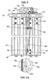
figure 2 schematically shows a front partially dissected view of the device of the present invention, applied to the same floor doors and arranged so as to allow the opening of the relevant doors; -
figure 2A schematically shows an enlarged detail offigure 1 , highlighting the arrangement of locking means arranged in the bottom part of floor doors; -
figure 3 schematically shows a front partially dissected view of the same device wherein one of the locking means is active; -
figure 3A schematically shows an enlarged detail offigure 3 highlighting the position of the only active locking means. - With initial reference to
figure 1 , the improved device for locking the floor doors of lifts of the present invention is applied to a pair of doors orpanels respective slides bottom threshold 16. According to a known embodiment, aprimary lock 24 is fixed tocrosspiece 22 of the floor door, whereto apivoting lock 26 constituting the primary lock is fixed. Said lock comprises a hook orbolt 28 that when the primary lock is active, engages withkeyholes slide 18 with the function of ensuring the safe locking ofdoor 12. - According to the invention, the improved device for locking the floor doors of lifts comprises a
second bolt 32, arranged at or in the proximity of the bottom end of the floor door and fixed inside one ofdoors second bolt 32, in particular, is articulated on asupport 34 constrained insidedoor 12, in the extreme lower end thereof, and can pivot along a plane parallel to those identifying the inside and outside surfaces ofdoors second bolt 32, which forms the secondary lock, is obtained through a plurality of linkages, as explained hereinafter. A first bar-shaped arm 36 or top connection extends vertically, starting from thepivoting lock 26 whereto it is connected by the top end thereof, indoor 12 reaching with the opposite end asecond arm 38, with a considerable shorter extension, whereto it is articulated in a substantially central position. Said second arm orintermediate arm 38 is turnably fixed with an end insidedoor 12; the same end carries a lock oremergency release 40, of the known type. The opposite end of thesecond arm 38 is articulated on athird arm 42, which in opposite position reaches and articulated-wise connects at 32' to thesecond bolt 32, articulated onsupport 34. Said latter is connected to therelevant support 34 so as to protrude during the pivoting ofdoor 12 and partly insert intodoor 10 next to the first one. For this reason, both said doors are provided, along the vertical side band that defines their approach face, with respectivevertical slits figures 2A and3A ; through such slits, bolt 32 exits fromdoor 12 and fits intodoor 10, releasing it. - Such movement requires the intervention of levers or
arms - Starting from the condition shown in
figure 1 , it is noted that the primary lock formed by thepivoting lock 26 is active, sincebolt 28 is hooked tokeyholes doors figure 1 it is also noted that the secondary lock consisting of thesecond bolt 32 is active since said bolt comes out ofdoor 12 andhooks door 10 crossing thevertical slits second bolt 32 thathooks door 10 is determined by the fact that the pivoting lock is lowered andlever 36 is equally lowered; this also leadsarm 42 or second connection to lower, moving thesecond bolt 32, articulated in 32' to the same arm, to hookdoor 10. - The simple pivoting of
lock 26, which occurs when the cabin slide (not shown) engages the wheels of thepivoting lock 26 and closing, partially rotates the same lock, releasesbolt 28; as a consequence, the top connection formed by thefirst arm 36 lifts and it also lifts the bottom connection consisting of thethird arm 42 whereto thesecond bolt 32 is connected. In this way, the two safeties, top and bottom, lock in a synchronous manner as shown infigure 2 and partly infigure 2A . - Said second bottom connection, in fact, lifts with the end of the
third arm 42 connected to theintermediate arm 38, moving along slot 48 created indoor 12 wherefrom it partly protrudes. While said slot allows lifting thesecond bolt 32 during any vandalic actions, however it does not allow also the release ofbolt 28, thus preventing the opening of the floor door. The emergency release actuated by a triangular key is of the known type and carries a lever that actuates the primary connection causing the opening of the primary lock; at the same time, said emergency release lifts the bottom connection that lifts the secondary lock, thus allowing the opening of the floor door. - As can be noticed from the above, the advantages achieved by the invention are clear. The improved device for locking floor doors of lifts of the present invention ensures excellent safety levels also against possible vandalic actions. This last hypothesis for which reference shall be made to
figure 3 , has a great importance considering that any tampering with release of thesecond bolt 32 is not sufficient to opendoors top bolt 28. The advantage consequent to the adoption of the dual safety according to the invention is also clear in the testing step, as thebottom bolt 32 does not allow the deviation ofdoors - Even if the invention has been described hereinbefore with particular reference to an embodiment thereof made by way of a non-limiting example, several changes and variations will appear clearly to a man skilled in the art in the light of the above description. This invention therefore is intended to include any changes and variations thereof falling within the spirit and the scope of protection of the following claims.
Claims (4)
- An improved device for locking the floor door of lifts, applied to a pair of doors or panels (10-12) of a floor door, sliding along an upper track (14) through respective slides (18-20) and along a lower threshold (16), comprising a primary keyhole (24), fixed to the crosspiece (22) of said floor door, whereto a pivoting lock (26) is connected, provided with a bolt (28) engaged with a primary keyhole (24) and a secondary keyhole (30), further comprising a second bolt (32), placed at or in the proximity of, the lower end of the floor door and fixed inside one of said doors (10) or (12), said second bolt being articulated on a support (34) connected to a plurality of linkages, characterised in that said plurality of linkages comprises a first top connection or arm (36) connected by an end to the pivoting lock (26) and at the opposite end, to an intermediate arm (38) provided with an emergency release (40) and with a slot (48) wherefrom it partially protrudes.
- The device according to claim 1, characterised in that said intermediate arm (38) is articulated, in a position opposite that of the emergency release (40), to a third arm or lower connection (42) that connects articulated-wise to the support (34) of the second bolt (32), said latter pivoting along a plane parallel to the plane that defines the inside and/or outside surface of the doors (10-12).
- The device according to claim 1, characterised in that the first arm or upper connection (36), the intermediate arm (38) and the third arm or lower connection (34) are actuated by the pivoting of the lock (26).
- The device according to claim 1, characterised in that the doors (10-12) are provided, along the vertical side band that defines their approach face, with respective slits (44-46) wherethrough the bolt (32) arranges during the coupling or safety engagement.
Applications Claiming Priority (1)
| Application Number | Priority Date | Filing Date | Title |
|---|---|---|---|
| ITMI2009A001682A IT1398157B1 (en) | 2009-09-30 | 2009-09-30 | IMPROVED DEVICE FOR LOCKING THE LIFT FLOOR DOORS |
Publications (2)
| Publication Number | Publication Date |
|---|---|
| EP2305592A1 true EP2305592A1 (en) | 2011-04-06 |
| EP2305592B1 EP2305592B1 (en) | 2013-01-23 |
Family
ID=42077040
Family Applications (1)
| Application Number | Title | Priority Date | Filing Date |
|---|---|---|---|
| EP20100010468 Active EP2305592B1 (en) | 2009-09-30 | 2010-09-24 | Landing door lock |
Country Status (2)
| Country | Link |
|---|---|
| EP (1) | EP2305592B1 (en) |
| IT (1) | IT1398157B1 (en) |
Cited By (1)
| Publication number | Priority date | Publication date | Assignee | Title |
|---|---|---|---|---|
| CN102951529A (en) * | 2011-08-17 | 2013-03-06 | 上海三菱电梯有限公司 | Elevator car door locking device |
Citations (2)
| Publication number | Priority date | Publication date | Assignee | Title |
|---|---|---|---|---|
| US1525215A (en) * | 1922-06-14 | 1925-02-03 | George F Botscheider | Elevator switch lock |
| EP0498025A2 (en) | 1991-02-08 | 1992-08-12 | C. HAUSHAHN GmbH & Co. | Locking device |
-
2009
- 2009-09-30 IT ITMI2009A001682A patent/IT1398157B1/en active
-
2010
- 2010-09-24 EP EP20100010468 patent/EP2305592B1/en active Active
Patent Citations (2)
| Publication number | Priority date | Publication date | Assignee | Title |
|---|---|---|---|---|
| US1525215A (en) * | 1922-06-14 | 1925-02-03 | George F Botscheider | Elevator switch lock |
| EP0498025A2 (en) | 1991-02-08 | 1992-08-12 | C. HAUSHAHN GmbH & Co. | Locking device |
Cited By (2)
| Publication number | Priority date | Publication date | Assignee | Title |
|---|---|---|---|---|
| CN102951529A (en) * | 2011-08-17 | 2013-03-06 | 上海三菱电梯有限公司 | Elevator car door locking device |
| CN102951529B (en) * | 2011-08-17 | 2015-04-01 | 上海三菱电梯有限公司 | Elevator car door locking device |
Also Published As
| Publication number | Publication date |
|---|---|
| ITMI20091682A1 (en) | 2011-04-01 |
| EP2305592B1 (en) | 2013-01-23 |
| IT1398157B1 (en) | 2013-02-14 |
Similar Documents
| Publication | Publication Date | Title |
|---|---|---|
| CA2166841C (en) | Temporary working space protection | |
| EP1110900B1 (en) | Shaft safety system for an elevator | |
| US8936064B1 (en) | Trolley lock for a garage door opener | |
| KR100984073B1 (en) | Locking apparatus of the platform screen door system | |
| CN109573796B (en) | Machinery shaft entrance control device | |
| CN105307964A (en) | Elevator shaft with reduced shaft pit or reduced shaft top | |
| JP5888262B2 (en) | Elevator hall door unlocking device | |
| CN106081820B (en) | Elevator car door locking device and elevator | |
| EP2305592B1 (en) | Landing door lock | |
| KR102094885B1 (en) | Elevator door locking implement | |
| CN203715014U (en) | Device for stopping human body during abnormal starting of elevator landing door | |
| CN203922351U (en) | An elevator floor door accidental opening limiter device | |
| US20250388434A1 (en) | Coupling and locking device for synchronous doors of an elevator equipment | |
| JP2002293488A (en) | lift device | |
| JP6777033B2 (en) | Elevator landing door unlocking device | |
| US5855253A (en) | Mechanical security device for elevators used between two levels | |
| WO2017017702A1 (en) | Lock strike plate provided with an emergency unlocking system, and lock-ing device comprising said lock strike plate | |
| CN117228485A (en) | A kind of hall door interlocking mechanism to ensure the safety of maintenance personnel | |
| CN207017812U (en) | It is a kind of with the elevator inlay door locking device opened in advance | |
| US3998484A (en) | Sliding door locking device | |
| JPH0522545Y2 (en) | ||
| KR200474195Y1 (en) | Goods lift | |
| CN218160060U (en) | Grounding switch padlock device | |
| CN113682928B (en) | Elevator layer door lock structure | |
| KR20110046898A (en) | Departure preventing device for landing door of elevator |
Legal Events
| Date | Code | Title | Description |
|---|---|---|---|
| PUAI | Public reference made under article 153(3) epc to a published international application that has entered the european phase |
Free format text: ORIGINAL CODE: 0009012 |
|
| AK | Designated contracting states |
Kind code of ref document: A1 Designated state(s): AL AT BE BG CH CY CZ DE DK EE ES FI FR GB GR HR HU IE IS IT LI LT LU LV MC MK MT NL NO PL PT RO SE SI SK SM TR |
|
| AX | Request for extension of the european patent |
Extension state: BA ME RS |
|
| 17P | Request for examination filed |
Effective date: 20111005 |
|
| RAP1 | Party data changed (applicant data changed or rights of an application transferred) |
Owner name: SEMATIC S.P.A. |
|
| GRAP | Despatch of communication of intention to grant a patent |
Free format text: ORIGINAL CODE: EPIDOSNIGR1 |
|
| GRAS | Grant fee paid |
Free format text: ORIGINAL CODE: EPIDOSNIGR3 |
|
| GRAA | (expected) grant |
Free format text: ORIGINAL CODE: 0009210 |
|
| AK | Designated contracting states |
Kind code of ref document: B1 Designated state(s): AL AT BE BG CH CY CZ DE DK EE ES FI FR GB GR HR HU IE IS IT LI LT LU LV MC MK MT NL NO PL PT RO SE SI SK SM TR |
|
| REG | Reference to a national code |
Ref country code: GB Ref legal event code: FG4D |
|
| REG | Reference to a national code |
Ref country code: CH Ref legal event code: EP |
|
| REG | Reference to a national code |
Ref country code: AT Ref legal event code: REF Ref document number: 594841 Country of ref document: AT Kind code of ref document: T Effective date: 20130215 Ref country code: CH Ref legal event code: EP |
|
| REG | Reference to a national code |
Ref country code: IE Ref legal event code: FG4D |
|
| REG | Reference to a national code |
Ref country code: CH Ref legal event code: NV Representative=s name: JACOBACCI AND PARTNERS S.P.A., CH |
|
| REG | Reference to a national code |
Ref country code: DE Ref legal event code: R096 Ref document number: 602010004753 Country of ref document: DE Effective date: 20130321 |
|
| REG | Reference to a national code |
Ref country code: AT Ref legal event code: MK05 Ref document number: 594841 Country of ref document: AT Kind code of ref document: T Effective date: 20130123 |
|
| REG | Reference to a national code |
Ref country code: LT Ref legal event code: MG4D |
|
| REG | Reference to a national code |
Ref country code: NL Ref legal event code: VDEP Effective date: 20130123 |
|
| PG25 | Lapsed in a contracting state [announced via postgrant information from national office to epo] |
Ref country code: NO Free format text: LAPSE BECAUSE OF FAILURE TO SUBMIT A TRANSLATION OF THE DESCRIPTION OR TO PAY THE FEE WITHIN THE PRESCRIBED TIME-LIMIT Effective date: 20130423 Ref country code: BE Free format text: LAPSE BECAUSE OF FAILURE TO SUBMIT A TRANSLATION OF THE DESCRIPTION OR TO PAY THE FEE WITHIN THE PRESCRIBED TIME-LIMIT Effective date: 20130123 Ref country code: ES Free format text: LAPSE BECAUSE OF FAILURE TO SUBMIT A TRANSLATION OF THE DESCRIPTION OR TO PAY THE FEE WITHIN THE PRESCRIBED TIME-LIMIT Effective date: 20130504 Ref country code: IS Free format text: LAPSE BECAUSE OF FAILURE TO SUBMIT A TRANSLATION OF THE DESCRIPTION OR TO PAY THE FEE WITHIN THE PRESCRIBED TIME-LIMIT Effective date: 20130523 Ref country code: BG Free format text: LAPSE BECAUSE OF FAILURE TO SUBMIT A TRANSLATION OF THE DESCRIPTION OR TO PAY THE FEE WITHIN THE PRESCRIBED TIME-LIMIT Effective date: 20130423 Ref country code: AT Free format text: LAPSE BECAUSE OF FAILURE TO SUBMIT A TRANSLATION OF THE DESCRIPTION OR TO PAY THE FEE WITHIN THE PRESCRIBED TIME-LIMIT Effective date: 20130123 Ref country code: LT Free format text: LAPSE BECAUSE OF FAILURE TO SUBMIT A TRANSLATION OF THE DESCRIPTION OR TO PAY THE FEE WITHIN THE PRESCRIBED TIME-LIMIT Effective date: 20130123 Ref country code: SE Free format text: LAPSE BECAUSE OF FAILURE TO SUBMIT A TRANSLATION OF THE DESCRIPTION OR TO PAY THE FEE WITHIN THE PRESCRIBED TIME-LIMIT Effective date: 20130123 |
|
| PG25 | Lapsed in a contracting state [announced via postgrant information from national office to epo] |
Ref country code: LV Free format text: LAPSE BECAUSE OF FAILURE TO SUBMIT A TRANSLATION OF THE DESCRIPTION OR TO PAY THE FEE WITHIN THE PRESCRIBED TIME-LIMIT Effective date: 20130123 Ref country code: NL Free format text: LAPSE BECAUSE OF FAILURE TO SUBMIT A TRANSLATION OF THE DESCRIPTION OR TO PAY THE FEE WITHIN THE PRESCRIBED TIME-LIMIT Effective date: 20130123 Ref country code: PT Free format text: LAPSE BECAUSE OF FAILURE TO SUBMIT A TRANSLATION OF THE DESCRIPTION OR TO PAY THE FEE WITHIN THE PRESCRIBED TIME-LIMIT Effective date: 20130523 Ref country code: GR Free format text: LAPSE BECAUSE OF FAILURE TO SUBMIT A TRANSLATION OF THE DESCRIPTION OR TO PAY THE FEE WITHIN THE PRESCRIBED TIME-LIMIT Effective date: 20130424 Ref country code: PL Free format text: LAPSE BECAUSE OF FAILURE TO SUBMIT A TRANSLATION OF THE DESCRIPTION OR TO PAY THE FEE WITHIN THE PRESCRIBED TIME-LIMIT Effective date: 20130123 Ref country code: FI Free format text: LAPSE BECAUSE OF FAILURE TO SUBMIT A TRANSLATION OF THE DESCRIPTION OR TO PAY THE FEE WITHIN THE PRESCRIBED TIME-LIMIT Effective date: 20130123 Ref country code: SI Free format text: LAPSE BECAUSE OF FAILURE TO SUBMIT A TRANSLATION OF THE DESCRIPTION OR TO PAY THE FEE WITHIN THE PRESCRIBED TIME-LIMIT Effective date: 20130123 |
|
| PG25 | Lapsed in a contracting state [announced via postgrant information from national office to epo] |
Ref country code: HR Free format text: LAPSE BECAUSE OF FAILURE TO SUBMIT A TRANSLATION OF THE DESCRIPTION OR TO PAY THE FEE WITHIN THE PRESCRIBED TIME-LIMIT Effective date: 20130123 |
|
| REG | Reference to a national code |
Ref country code: HU Ref legal event code: AG4A Ref document number: E016536 Country of ref document: HU |
|
| PG25 | Lapsed in a contracting state [announced via postgrant information from national office to epo] |
Ref country code: CZ Free format text: LAPSE BECAUSE OF FAILURE TO SUBMIT A TRANSLATION OF THE DESCRIPTION OR TO PAY THE FEE WITHIN THE PRESCRIBED TIME-LIMIT Effective date: 20130123 Ref country code: EE Free format text: LAPSE BECAUSE OF FAILURE TO SUBMIT A TRANSLATION OF THE DESCRIPTION OR TO PAY THE FEE WITHIN THE PRESCRIBED TIME-LIMIT Effective date: 20130123 Ref country code: DK Free format text: LAPSE BECAUSE OF FAILURE TO SUBMIT A TRANSLATION OF THE DESCRIPTION OR TO PAY THE FEE WITHIN THE PRESCRIBED TIME-LIMIT Effective date: 20130123 Ref country code: RO Free format text: LAPSE BECAUSE OF FAILURE TO SUBMIT A TRANSLATION OF THE DESCRIPTION OR TO PAY THE FEE WITHIN THE PRESCRIBED TIME-LIMIT Effective date: 20130123 Ref country code: SK Free format text: LAPSE BECAUSE OF FAILURE TO SUBMIT A TRANSLATION OF THE DESCRIPTION OR TO PAY THE FEE WITHIN THE PRESCRIBED TIME-LIMIT Effective date: 20130123 |
|
| PG25 | Lapsed in a contracting state [announced via postgrant information from national office to epo] |
Ref country code: CY Free format text: LAPSE BECAUSE OF FAILURE TO SUBMIT A TRANSLATION OF THE DESCRIPTION OR TO PAY THE FEE WITHIN THE PRESCRIBED TIME-LIMIT Effective date: 20130123 |
|
| PLBE | No opposition filed within time limit |
Free format text: ORIGINAL CODE: 0009261 |
|
| STAA | Information on the status of an ep patent application or granted ep patent |
Free format text: STATUS: NO OPPOSITION FILED WITHIN TIME LIMIT |
|
| 26N | No opposition filed |
Effective date: 20131024 |
|
| REG | Reference to a national code |
Ref country code: DE Ref legal event code: R097 Ref document number: 602010004753 Country of ref document: DE Effective date: 20131024 |
|
| PG25 | Lapsed in a contracting state [announced via postgrant information from national office to epo] |
Ref country code: MC Free format text: LAPSE BECAUSE OF FAILURE TO SUBMIT A TRANSLATION OF THE DESCRIPTION OR TO PAY THE FEE WITHIN THE PRESCRIBED TIME-LIMIT Effective date: 20130123 |
|
| REG | Reference to a national code |
Ref country code: IE Ref legal event code: MM4A |
|
| PG25 | Lapsed in a contracting state [announced via postgrant information from national office to epo] |
Ref country code: IE Free format text: LAPSE BECAUSE OF NON-PAYMENT OF DUE FEES Effective date: 20130924 |
|
| REG | Reference to a national code |
Ref country code: CH Ref legal event code: PCAR Free format text: NEW ADDRESS: VIA LUGANETTO 3, 6962 LUGANO (CH) |
|
| GBPC | Gb: european patent ceased through non-payment of renewal fee |
Effective date: 20140924 |
|
| PG25 | Lapsed in a contracting state [announced via postgrant information from national office to epo] |
Ref country code: SM Free format text: LAPSE BECAUSE OF FAILURE TO SUBMIT A TRANSLATION OF THE DESCRIPTION OR TO PAY THE FEE WITHIN THE PRESCRIBED TIME-LIMIT Effective date: 20130123 |
|
| PG25 | Lapsed in a contracting state [announced via postgrant information from national office to epo] |
Ref country code: TR Free format text: LAPSE BECAUSE OF FAILURE TO SUBMIT A TRANSLATION OF THE DESCRIPTION OR TO PAY THE FEE WITHIN THE PRESCRIBED TIME-LIMIT Effective date: 20130123 Ref country code: MT Free format text: LAPSE BECAUSE OF FAILURE TO SUBMIT A TRANSLATION OF THE DESCRIPTION OR TO PAY THE FEE WITHIN THE PRESCRIBED TIME-LIMIT Effective date: 20130123 |
|
| PG25 | Lapsed in a contracting state [announced via postgrant information from national office to epo] |
Ref country code: LU Free format text: LAPSE BECAUSE OF NON-PAYMENT OF DUE FEES Effective date: 20130924 Ref country code: GB Free format text: LAPSE BECAUSE OF NON-PAYMENT OF DUE FEES Effective date: 20140924 Ref country code: MK Free format text: LAPSE BECAUSE OF FAILURE TO SUBMIT A TRANSLATION OF THE DESCRIPTION OR TO PAY THE FEE WITHIN THE PRESCRIBED TIME-LIMIT Effective date: 20130123 |
|
| REG | Reference to a national code |
Ref country code: FR Ref legal event code: PLFP Year of fee payment: 7 |
|
| REG | Reference to a national code |
Ref country code: FR Ref legal event code: PLFP Year of fee payment: 8 |
|
| REG | Reference to a national code |
Ref country code: FR Ref legal event code: PLFP Year of fee payment: 9 |
|
| PG25 | Lapsed in a contracting state [announced via postgrant information from national office to epo] |
Ref country code: AL Free format text: LAPSE BECAUSE OF FAILURE TO SUBMIT A TRANSLATION OF THE DESCRIPTION OR TO PAY THE FEE WITHIN THE PRESCRIBED TIME-LIMIT Effective date: 20130123 |
|
| PGFP | Annual fee paid to national office [announced via postgrant information from national office to epo] |
Ref country code: HU Payment date: 20220920 Year of fee payment: 13 |
|
| PGFP | Annual fee paid to national office [announced via postgrant information from national office to epo] |
Ref country code: CH Payment date: 20220928 Year of fee payment: 13 |
|
| REG | Reference to a national code |
Ref country code: CH Ref legal event code: PL |
|
| PG25 | Lapsed in a contracting state [announced via postgrant information from national office to epo] |
Ref country code: CH Free format text: LAPSE BECAUSE OF NON-PAYMENT OF DUE FEES Effective date: 20230930 |
|
| PG25 | Lapsed in a contracting state [announced via postgrant information from national office to epo] |
Ref country code: CH Free format text: LAPSE BECAUSE OF NON-PAYMENT OF DUE FEES Effective date: 20230930 |
|
| PG25 | Lapsed in a contracting state [announced via postgrant information from national office to epo] |
Ref country code: HU Free format text: LAPSE BECAUSE OF NON-PAYMENT OF DUE FEES Effective date: 20230925 |
|
| PGFP | Annual fee paid to national office [announced via postgrant information from national office to epo] |
Ref country code: DE Payment date: 20240911 Year of fee payment: 15 |
|
| PGFP | Annual fee paid to national office [announced via postgrant information from national office to epo] |
Ref country code: FR Payment date: 20240829 Year of fee payment: 15 |
|
| PGFP | Annual fee paid to national office [announced via postgrant information from national office to epo] |
Ref country code: IT Payment date: 20240806 Year of fee payment: 15 |
|
| REG | Reference to a national code |
Ref country code: DE Ref legal event code: R119 Ref document number: 602010004753 Country of ref document: DE |
|
| PG25 | Lapsed in a contracting state [announced via postgrant information from national office to epo] |
Ref country code: IT Free format text: LAPSE BECAUSE OF NON-PAYMENT OF DUE FEES Effective date: 20250924 |
|
| PG25 | Lapsed in a contracting state [announced via postgrant information from national office to epo] |
Ref country code: DE Free format text: LAPSE BECAUSE OF NON-PAYMENT OF DUE FEES Effective date: 20260401 |
|
| PG25 | Lapsed in a contracting state [announced via postgrant information from national office to epo] |
Ref country code: FR Free format text: LAPSE BECAUSE OF NON-PAYMENT OF DUE FEES Effective date: 20250930 |