EP2305552A2 - System and method for reducing volatile organic compounds for an oil carrier - Google Patents
System and method for reducing volatile organic compounds for an oil carrier Download PDFInfo
- Publication number
- EP2305552A2 EP2305552A2 EP09798097A EP09798097A EP2305552A2 EP 2305552 A2 EP2305552 A2 EP 2305552A2 EP 09798097 A EP09798097 A EP 09798097A EP 09798097 A EP09798097 A EP 09798097A EP 2305552 A2 EP2305552 A2 EP 2305552A2
- Authority
- EP
- European Patent Office
- Prior art keywords
- crude oil
- storage tank
- pipe
- oil storage
- load pipe
- Prior art date
- Legal status (The legal status is an assumption and is not a legal conclusion. Google has not performed a legal analysis and makes no representation as to the accuracy of the status listed.)
- Granted
Links
Images
Classifications
-
- B—PERFORMING OPERATIONS; TRANSPORTING
- B63—SHIPS OR OTHER WATERBORNE VESSELS; RELATED EQUIPMENT
- B63B—SHIPS OR OTHER WATERBORNE VESSELS; EQUIPMENT FOR SHIPPING
- B63B11/00—Interior subdivision of hulls
- B63B11/04—Constructional features of bunkers, e.g. structural fuel tanks, or ballast tanks, e.g. with elastic walls
-
- B—PERFORMING OPERATIONS; TRANSPORTING
- B63—SHIPS OR OTHER WATERBORNE VESSELS; RELATED EQUIPMENT
- B63B—SHIPS OR OTHER WATERBORNE VESSELS; EQUIPMENT FOR SHIPPING
- B63B27/00—Arrangement of ship-based loading or unloading equipment for cargo or passengers
- B63B27/24—Arrangement of ship-based loading or unloading equipment for cargo or passengers of pipe-lines
-
- B—PERFORMING OPERATIONS; TRANSPORTING
- B63—SHIPS OR OTHER WATERBORNE VESSELS; RELATED EQUIPMENT
- B63B—SHIPS OR OTHER WATERBORNE VESSELS; EQUIPMENT FOR SHIPPING
- B63B25/00—Load-accommodating arrangements, e.g. stowing, trimming; Vessels characterised thereby
- B63B25/02—Load-accommodating arrangements, e.g. stowing, trimming; Vessels characterised thereby for bulk goods
- B63B25/08—Load-accommodating arrangements, e.g. stowing, trimming; Vessels characterised thereby for bulk goods fluid
-
- B—PERFORMING OPERATIONS; TRANSPORTING
- B63—SHIPS OR OTHER WATERBORNE VESSELS; RELATED EQUIPMENT
- B63B—SHIPS OR OTHER WATERBORNE VESSELS; EQUIPMENT FOR SHIPPING
- B63B25/00—Load-accommodating arrangements, e.g. stowing, trimming; Vessels characterised thereby
- B63B25/02—Load-accommodating arrangements, e.g. stowing, trimming; Vessels characterised thereby for bulk goods
- B63B25/08—Load-accommodating arrangements, e.g. stowing, trimming; Vessels characterised thereby for bulk goods fluid
- B63B25/12—Load-accommodating arrangements, e.g. stowing, trimming; Vessels characterised thereby for bulk goods fluid closed
-
- Y—GENERAL TAGGING OF NEW TECHNOLOGICAL DEVELOPMENTS; GENERAL TAGGING OF CROSS-SECTIONAL TECHNOLOGIES SPANNING OVER SEVERAL SECTIONS OF THE IPC; TECHNICAL SUBJECTS COVERED BY FORMER USPC CROSS-REFERENCE ART COLLECTIONS [XRACs] AND DIGESTS
- Y10—TECHNICAL SUBJECTS COVERED BY FORMER USPC
- Y10T—TECHNICAL SUBJECTS COVERED BY FORMER US CLASSIFICATION
- Y10T137/00—Fluid handling
- Y10T137/0318—Processes
- Y10T137/0324—With control of flow by a condition or characteristic of a fluid
- Y10T137/0379—By fluid pressure
-
- Y—GENERAL TAGGING OF NEW TECHNOLOGICAL DEVELOPMENTS; GENERAL TAGGING OF CROSS-SECTIONAL TECHNOLOGIES SPANNING OVER SEVERAL SECTIONS OF THE IPC; TECHNICAL SUBJECTS COVERED BY FORMER USPC CROSS-REFERENCE ART COLLECTIONS [XRACs] AND DIGESTS
- Y10—TECHNICAL SUBJECTS COVERED BY FORMER USPC
- Y10T—TECHNICAL SUBJECTS COVERED BY FORMER US CLASSIFICATION
- Y10T137/00—Fluid handling
- Y10T137/6851—With casing, support, protector or static constructional installations
- Y10T137/6966—Static constructional installations
- Y10T137/6991—Ground supporting enclosure
- Y10T137/7025—Pipe line transport
Definitions
- the present invention relates to a system and method for decreasing volatile organic compounds (VOC) in a crude oil tanker, and more particularly, to a system and method for decreasing VOC in a crude oil tanker, which occur while the crude oil tanker is loaded with crude oil.
- VOC volatile organic compounds
- crude oil is extracted from an oil field, loaded into a crude oil tanker, and then transported to a destination at a long distance.
- a supply pipe is horizontally installed at an upper part of the crude oil tanker, that is, over the crude oil storage tank of the crude oil tanker.
- the supply pipe has an end connected to the crude oil storage tank on land.
- a load pipe is vertically connected to the bottom surface of the supply pipe.
- the load pipe vertically passes through the crude oil storage tank of the crude oil tanker and communicates with a lower part of the crude oil storage tank of the crude oil tanker.
- a distribution pipe is installed at a lower end of the load pipe.
- a flow cavitation may be caused at the upper end part of the load pipe by an excessive pressure drop which occurs while the flow rate of the crude oil increases. That is, when the static pressure of flow inside the load pipe is smaller than the vapor pressure of the flow, a flow cavitation occurs. When the static pressure of the flow is smaller than saturation pressure, flow evaporation occurs. As a result, the crude oil evaporates to generate VOC.
- VOC generated in such a manner are discharged to the air or sent back to the crude oil storage tank on land.
- the VOC When discharged to the air, the VOC may cause serious environmental problems such as ozone layer damage. Furthermore, although the VOC are sent back to the crude oil storage tank on land, the VOC should be treated. In this case, the facility and cost are required for treating the VOC.
- An embodiment of the present invention is directed to a system and method for decreasing VOC in a crude oil tanker, which is capable of preventing a flow cavitation from occurring at an upper end part of a crude oil load pipe.
- a system for decreasing VOC in a crude oil tanker includes: a supply pipe horizontally installed over a crude oil storage tank of the crude oil tanker and having an end connected to a crude oil storage tank on land; a load pipe vertically connected to a bottom surface of the supply pipe, vertically passing through the crude oil storage tank of the crude oil tanker, and communicating with a lower part of the crude oil storage tank; a distribution pipe horizontally connected to a lower end of the load pipe; and a pressure control unit installed at a lower end portion of the load pipe.
- a method for decreasing VOC in a crude oil tanker including: supplying and loading crude oil into a crude oil storage tank of the crude oil tanker from a crude oil storage tank on land through a supply pipe horizontally installed over the crude oil storage tank of the crude oil tanker and having an end connected to the crude oil storage tank on land; a load pipe vertically connected to a bottom surface of the supply pipe, vertically passing through the crude oil storage tank of the crude oil tanker, and communicating with a lower part of the crude oil storage tank; and a distribution pipe horizontally connected to a lower end of the load pipe. Pressure inside the load pipe is controlled and maintained to vapor pressure of the crude oil or more.
- the pressure inside the load pipe is controlled at the lower end part of the load pipe and maintained to the vapor pressure of the crude oil or more. Therefore, although the crude oil horizontally-supplied from the horizontal supply pipe suddenly falls down at a portion where the crude oil meets the vertical load pipe, that is, at the upper end part of the load pipe and thus the flow rate of the crude oil increases, a flow cavitation does not occur at the upper end part of the load pipe. That is, when the static pressure of flow inside the load pipe is larger than the vapor pressure of the flow, a flow cavitation does not occur. Therefore, since the crude oil is not evaporated at the upper end part of the load pipe, VOC do not occur
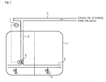
- FIG. 1 is a schematic view of a system for decreasing VOC in a crude oil tanker according to one embodiment of the present invention.
- FIG. 1 is a schematic view of a system for decreasing VOC in a crude oil tanker according to one embodiment of the present invention.
- a supply pipe 2 is horizontally installed at an upper part of the crude oil tanker, that is, over a crude oil storage tank 1 of the crude oil tanker.
- the supply pipe 2 has an end connected to a crude oil storage tank on land such that crude oil is supplied to the crude oil tanker from the crude oil storage tank on land.
- a load pipe 3 is vertically connected to the bottom surface of the supply pipe 2.
- the load pipe 3 vertically passes through the crude storage tank 1 of the crude oil tanker and communicates with a lower part of the crude storage tank 1 of the crude oil tanker.
- the load pipe 3 is used to load the crude oil, which is supplied through the supply pipe 2 from the crude oil storage tank on land, into the crude oil storage tank 1 of the crude oil tanker.
- a distribution pipe 4 is installed at the lower end of the load pipe 3.
- the distribution pipe 4 is used to distribute the crude oil, which is loaded into the crude oil storage tank 1 of the crude oil tanker through the load pipe 3, into the crude oil storage tank 1 of the crude oil tanker, and the distribution pipe 4 includes a distribution valve 5 installed thereon.
- a pressure control valve 6 is installed inside a lower end part of the load pipe 3.
- the pressure control valve 6 may include an anti-cavitation valve which may be formed by combining a relief valve and a check valve.
- the anti-cavitation valve is well-known in a valve-related technique field. Therefore, the detailed descriptions thereof will be omitted.
- the pressure control valve 6 is connected to a pressure transducer 7 for measuring pressure at the upper end part of the load pipe 3.
- the pressure control valve 6 controls the pressure inside the load pipe 3 based on the pressure at the upper end part of the load pipe 3, which is transmitted by the pressure transducer 7, and maintains the pressure to the stream pressure of the crude oil or more.
- the pressure inside the load pipe 3 is controlled at the lower end part of the load pipe 3 and maintained to the vapor pressure of the crude oil or more. Therefore, although the crude oil horizontally-supplied from the horizontal supply pipe 2 suddenly falls down at a portion where the crude oil meets the vertical load pipe 3, that is, at the upper end part of the load pipe 3 and thus the flow rate of the crude oil increases, a flow cavitation does not occur at the upper end part of the load pipe 3. That is, when the static pressure of flow inside the load pipe 3 is larger than the vapor pressure of the flow, a flow cavitation does not occur. Therefore, since the crude oil is not evaporated at the upper end part of the load pipe 3, VOC do not occur.
Landscapes
- Chemical & Material Sciences (AREA)
- Engineering & Computer Science (AREA)
- Combustion & Propulsion (AREA)
- Mechanical Engineering (AREA)
- Ocean & Marine Engineering (AREA)
- Production Of Liquid Hydrocarbon Mixture For Refining Petroleum (AREA)
- Loading And Unloading Of Fuel Tanks Or Ships (AREA)
Abstract
Description
- The present invention relates to a system and method for decreasing volatile organic compounds (VOC) in a crude oil tanker, and more particularly, to a system and method for decreasing VOC in a crude oil tanker, which occur while the crude oil tanker is loaded with crude oil.
- In general, crude oil is extracted from an oil field, loaded into a crude oil tanker, and then transported to a destination at a long distance.
- In a conventional crude oil tanker, a large amount of VOC occurs while crude oil is loaded into a crude oil storage tank of the crude oil tanker from a crude oil storage tank on land.
- In order to supply crude oil to the crude oil storage tank of the crude oil tanker from the crude oil storage tank on the land, a supply pipe is horizontally installed at an upper part of the crude oil tanker, that is, over the crude oil storage tank of the crude oil tanker. The supply pipe has an end connected to the crude oil storage tank on land. In order to load the crude oil, which is supplied from the crude oil storage tank on land through the supply pipe, into the crude oil storage tank of the crude oil tanker, a load pipe is vertically connected to the bottom surface of the supply pipe. The load pipe vertically passes through the crude oil storage tank of the crude oil tanker and communicates with a lower part of the crude oil storage tank of the crude oil tanker. Furthermore, in order to distribute the crude oil, which is loaded into the crude oil storage tank of the crude oil tanker through the load pipe, into the crude oil storage tank of the crude oil tanker, a distribution pipe is installed at a lower end of the load pipe.
- When the crude oil meets the vertical load pipe, that is, the upper end part of the load pipe while horizontally supplied from the horizontal supply pipe, the crude oil suddenly falls down. In this case, a flow cavitation may be caused at the upper end part of the load pipe by an excessive pressure drop which occurs while the flow rate of the crude oil increases. That is, when the static pressure of flow inside the load pipe is smaller than the vapor pressure of the flow, a flow cavitation occurs. When the static pressure of the flow is smaller than saturation pressure, flow evaporation occurs. As a result, the crude oil evaporates to generate VOC.
- The VOC generated in such a manner are discharged to the air or sent back to the crude oil storage tank on land.
- When discharged to the air, the VOC may cause serious environmental problems such as ozone layer damage. Furthermore, although the VOC are sent back to the crude oil storage tank on land, the VOC should be treated. In this case, the facility and cost are required for treating the VOC.
- An embodiment of the present invention is directed to a system and method for decreasing VOC in a crude oil tanker, which is capable of preventing a flow cavitation from occurring at an upper end part of a crude oil load pipe.
- According to an aspect of the present invention, a system for decreasing VOC in a crude oil tanker includes: a supply pipe horizontally installed over a crude oil storage tank of the crude oil tanker and having an end connected to a crude oil storage tank on land; a load pipe vertically connected to a bottom surface of the supply pipe, vertically passing through the crude oil storage tank of the crude oil tanker, and communicating with a lower part of the crude oil storage tank; a distribution pipe horizontally connected to a lower end of the load pipe; and a pressure control unit installed at a lower end portion of the load pipe.
- According to another aspect of the present invention, there is provided a method for decreasing VOC in a crude oil tanker, including: supplying and loading crude oil into a crude oil storage tank of the crude oil tanker from a crude oil storage tank on land through a supply pipe horizontally installed over the crude oil storage tank of the crude oil tanker and having an end connected to the crude oil storage tank on land; a load pipe vertically connected to a bottom surface of the supply pipe, vertically passing through the crude oil storage tank of the crude oil tanker, and communicating with a lower part of the crude oil storage tank; and a distribution pipe horizontally connected to a lower end of the load pipe. Pressure inside the load pipe is controlled and maintained to vapor pressure of the crude oil or more.
- It should be understood that different embodiments of the invention, including those described under different aspects of the invention, are meant to be generally applicable to all aspects of the invention. Any embodiment may be combined with any other embodiment unless inappropriate. All examples are illustrative and non-limiting.
- According to the embodiment of the present invention, the pressure inside the load pipe is controlled at the lower end part of the load pipe and maintained to the vapor pressure of the crude oil or more. Therefore, although the crude oil horizontally-supplied from the horizontal supply pipe suddenly falls down at a portion where the crude oil meets the vertical load pipe, that is, at the upper end part of the load pipe and thus the flow rate of the crude oil increases, a flow cavitation does not occur at the upper end part of the load pipe. That is, when the static pressure of flow inside the load pipe is larger than the vapor pressure of the flow, a flow cavitation does not occur. Therefore, since the crude oil is not evaporated at the upper end part of the load pipe, VOC do not occur
-
FIG. 1 is a schematic view of a system for decreasing VOC in a crude oil tanker according to one embodiment of the present invention. - Exemplary embodiments of the present invention will be described below in more detail with reference to the accompanying drawings. The present invention may, however, be embodied in different forms and should not be constructed as limited to the embodiments set forth herein. Rather, these embodiments are provided so that this disclosure will be thorough and complete, and will fully convey the scope of the present invention to those skilled in the art. Throughout the disclosure, like reference numerals refer to like parts throughout the various figures and embodiments of the present invention.
-
FIG. 1 is a schematic view of a system for decreasing VOC in a crude oil tanker according to one embodiment of the present invention. - Referring to
FIG. 1 , asupply pipe 2 is horizontally installed at an upper part of the crude oil tanker, that is, over a crude oil storage tank 1 of the crude oil tanker. Thesupply pipe 2 has an end connected to a crude oil storage tank on land such that crude oil is supplied to the crude oil tanker from the crude oil storage tank on land. - Furthermore, a
load pipe 3 is vertically connected to the bottom surface of thesupply pipe 2. Theload pipe 3 vertically passes through the crude storage tank 1 of the crude oil tanker and communicates with a lower part of the crude storage tank 1 of the crude oil tanker. Theload pipe 3 is used to load the crude oil, which is supplied through thesupply pipe 2 from the crude oil storage tank on land, into the crude oil storage tank 1 of the crude oil tanker. - Furthermore, a distribution pipe 4 is installed at the lower end of the
load pipe 3. The distribution pipe 4 is used to distribute the crude oil, which is loaded into the crude oil storage tank 1 of the crude oil tanker through theload pipe 3, into the crude oil storage tank 1 of the crude oil tanker, and the distribution pipe 4 includes adistribution valve 5 installed thereon. - Furthermore, a
pressure control valve 6 is installed inside a lower end part of theload pipe 3. Thepressure control valve 6 may include an anti-cavitation valve which may be formed by combining a relief valve and a check valve. The anti-cavitation valve is well-known in a valve-related technique field. Therefore, the detailed descriptions thereof will be omitted. - The
pressure control valve 6 is connected to a pressure transducer 7 for measuring pressure at the upper end part of theload pipe 3. Thepressure control valve 6 controls the pressure inside theload pipe 3 based on the pressure at the upper end part of theload pipe 3, which is transmitted by the pressure transducer 7, and maintains the pressure to the stream pressure of the crude oil or more. - In this embodiment, the pressure inside the
load pipe 3 is controlled at the lower end part of theload pipe 3 and maintained to the vapor pressure of the crude oil or more. Therefore, although the crude oil horizontally-supplied from thehorizontal supply pipe 2 suddenly falls down at a portion where the crude oil meets thevertical load pipe 3, that is, at the upper end part of theload pipe 3 and thus the flow rate of the crude oil increases, a flow cavitation does not occur at the upper end part of theload pipe 3. That is, when the static pressure of flow inside theload pipe 3 is larger than the vapor pressure of the flow, a flow cavitation does not occur. Therefore, since the crude oil is not evaporated at the upper end part of theload pipe 3, VOC do not occur. - While the present invention has been described with respect to the specific embodiments, it will be apparent to those skilled in the art that various changes and modifications may be made without departing from the spirit and scope of the invention as defined in the following claims.
Claims (6)
- A system for decreasing volatile organic compounds (VOC) in a crude oil tanker, comprising:a supply pipe horizontally installed over a crude oil storage tank of the crude oil tanker and having an end connected to a crude oil storage tank on land;a load pipe vertically connected to a bottom surface of the supply pipe, vertically passing through the crude oil storage tank of the crude oil tanker, and communicating with a lower part of the crude oil storage tank;a distribution pipe horizontally connected to a lower end of the load pipe; anda pressure control unit installed at a lower end portion of the load pipe.
- The system according to claim 1, further comprising a pressure transducer measuring pressure at an upper end part of the load pipe and transmitting the measured pressure to the pressure control unit.
- The system according to claim 1 or 2, wherein the pressure control unit comprises an anti-cavitation valve.
- A method for decreasing VOC in a crude oil tanker, comprising:supplying and loading crude oil into a crude oil storage tank of the crude oil tanker from a crude oil storage tank on land through a supply pipe horizontally installed over the crude oil storage tank of the crude oil tanker and having an end connected to the crude oil storage tank on land; a load pipe vertically connected to a bottom surface of the supply pipe, vertically passing through the crude oil storage tank of the crude oil tanker, and communicating with a lower part of the crude oil storage tank; and a distribution pipe horizontally connected to a lower end of the load pipe,wherein pressure inside the load pipe is controlled and maintained to vapor pressure of the crude oil or more.
- The method according to claim 4, wherein the pressure inside the load pipe is controlled at a lower end part of the load pipe.
- The method according to claim 4 or 5, wherein pressure at an upper end part of the load pipe is measured, and the pressure inside the load pipe is controlled on the basis of the measured pressure.
Applications Claiming Priority (2)
| Application Number | Priority Date | Filing Date | Title |
|---|---|---|---|
| KR1020080069017A KR101012643B1 (en) | 2008-07-16 | 2008-07-16 | System and Method for Reducing Volatile Organic Compounds in Crude Oil Carriers |
| PCT/KR2009/003880 WO2010008194A2 (en) | 2008-07-16 | 2009-07-15 | System and method for reducing volatile organic compounds for an oil carrier |
Publications (3)
| Publication Number | Publication Date |
|---|---|
| EP2305552A2 true EP2305552A2 (en) | 2011-04-06 |
| EP2305552A4 EP2305552A4 (en) | 2013-05-01 |
| EP2305552B1 EP2305552B1 (en) | 2014-09-24 |
Family
ID=41550837
Family Applications (1)
| Application Number | Title | Priority Date | Filing Date |
|---|---|---|---|
| EP20090798097 Active EP2305552B1 (en) | 2008-07-16 | 2009-07-15 | System and method for reducing volatile organic compounds for an oil carrier |
Country Status (6)
| Country | Link |
|---|---|
| US (1) | US8561634B2 (en) |
| EP (1) | EP2305552B1 (en) |
| JP (3) | JP5520943B2 (en) |
| KR (1) | KR101012643B1 (en) |
| CN (2) | CN103991835A (en) |
| WO (1) | WO2010008194A2 (en) |
Cited By (1)
| Publication number | Priority date | Publication date | Assignee | Title |
|---|---|---|---|---|
| EP2902310A4 (en) * | 2012-09-27 | 2016-05-25 | Samsung Heavy Ind | OIL SUPPLY DEVICE AND OIL BARRIER HAVING THE SAME |
Families Citing this family (19)
| Publication number | Priority date | Publication date | Assignee | Title |
|---|---|---|---|---|
| KR101012643B1 (en) * | 2008-07-16 | 2011-02-09 | 대우조선해양 주식회사 | System and Method for Reducing Volatile Organic Compounds in Crude Oil Carriers |
| KR101460251B1 (en) * | 2009-11-12 | 2014-11-10 | 대우조선해양 주식회사 | Crude oil tanker |
| NO331559B1 (en) * | 2010-03-08 | 2012-01-23 | Hamworthy Oil & Gas Systems As | System for reducing emissions from volatile liquid cargo |
| KR101138347B1 (en) * | 2010-03-10 | 2012-04-26 | 삼성중공업 주식회사 | System for loading crude oil and oil tanker have the same |
| KR101665320B1 (en) * | 2010-06-24 | 2016-10-13 | 대우조선해양 주식회사 | Apparatus for decreasing volatile organic components |
| KR101224918B1 (en) * | 2010-07-23 | 2013-01-22 | 삼성중공업 주식회사 | Lng loading pipe device and loading method using the same |
| KR101291352B1 (en) * | 2011-03-04 | 2013-07-30 | 삼성중공업 주식회사 | Oil loading and unloading apparatus for oil tanker |
| KR101239986B1 (en) * | 2011-05-18 | 2013-03-06 | 삼성중공업 주식회사 | Liquid cargo storage tank |
| KR101291357B1 (en) * | 2011-06-22 | 2013-07-30 | 삼성중공업 주식회사 | VOC reducing apparatus for liquid cargo storage tank |
| KR101291360B1 (en) * | 2011-07-01 | 2013-07-30 | 삼성중공업 주식회사 | VOC reducing apparatus for liquid cargo storage tank |
| KR101291361B1 (en) * | 2011-07-06 | 2013-07-30 | 삼성중공업 주식회사 | Liquid cargo storage equipment |
| KR101465685B1 (en) * | 2012-06-27 | 2014-11-26 | 삼성중공업 주식회사 | Apparatus for loading storage tank with oil and oil carrier having the same |
| KR101408347B1 (en) * | 2013-09-06 | 2014-06-17 | 대우조선해양 주식회사 | Vaporization reducing system and method of liquid cargo for a ship |
| KR101444380B1 (en) * | 2013-11-04 | 2014-09-29 | 삼성중공업 주식회사 | Apparatus for loading storage tank with oil and oil carrier having the same |
| KR101571411B1 (en) * | 2014-07-04 | 2015-11-24 | 삼성중공업 주식회사 | Valve and oil loading system including the same |
| KR101707514B1 (en) | 2015-01-21 | 2017-02-16 | 대우조선해양 주식회사 | Vaporization reducing system and method of liquid cargo |
| RU2689458C1 (en) * | 2018-04-26 | 2019-05-28 | Публичное акционерное общество "Транснефть" (ПАО "Транснефть") | Method for oil compounding and system for its implementation |
| US10988214B1 (en) | 2020-02-04 | 2021-04-27 | G Squared V LLC | Offshore transfer and destruction of volatile organic compounds |
| NO347384B1 (en) * | 2021-10-26 | 2023-10-09 | Gba Marine As | Liquid loading assembly for loading a ship-hold or tank |
Family Cites Families (17)
| Publication number | Priority date | Publication date | Assignee | Title |
|---|---|---|---|---|
| GB847199A (en) * | 1958-10-10 | 1960-09-07 | Shell Res Ltd | Improvements in or relating to the construction and operation of oil tankers |
| US3213632A (en) * | 1960-03-07 | 1965-10-26 | California Texas Oil Corp | Ship for transporting liquefied gases and other liquids |
| NO148481C (en) * | 1980-07-08 | 1983-10-19 | Moss Rosenberg Verft As | PROCEDURE FOR TRANSPORTING OIL AND GAS UNDER HIGH PRESSURE IN TANKER ON BOARD OF A SHIP |
| JPS6215097U (en) * | 1985-07-12 | 1987-01-29 | ||
| JPS6233597U (en) * | 1985-08-15 | 1987-02-27 | ||
| US4981153A (en) * | 1990-05-21 | 1991-01-01 | Atlantic Richfield Company | Method and apparatus for reducing hydrocarbon vapor emission from a storage tank |
| JPH05187410A (en) * | 1992-01-16 | 1993-07-27 | Yutani Heavy Ind Ltd | Cavitation preventing device for hydraulic cylinder |
| HUP9800578A1 (en) * | 1998-03-16 | 1999-11-29 | István Szakály | Process and apparatus for eliminating filling and evaporation loss of volatile materials storaged in tank, and for protection of corrosion of the storaged product and tank |
| NO315214B1 (en) * | 2001-04-03 | 2003-07-28 | Knutsen Oas Shipping As | Method and device for petroleum loading. (Evaporative tank over tire and compressors with pressure storage tanks) |
| NO319972B1 (en) * | 2001-06-26 | 2005-10-03 | Knutsen Oas Shipping As | Method and apparatus for reducing the separation of volatile organic compounds from oil during tank filling |
| NO315293B1 (en) * | 2001-10-31 | 2003-08-11 | Procyss As | Process for absorbing vapors and gases in the control of overpressure storage tanks for liquids and application of the process |
| NO315417B1 (en) * | 2001-12-06 | 2003-09-01 | Knutsen Oas Shipping As | Method and arrangement of loading column |
| NO316739B1 (en) * | 2002-05-31 | 2004-04-19 | Knutsen Oas Shipping As | Process for reducing the separation of volatile organic compounds from oil during filling of tanks |
| NO321880B1 (en) * | 2002-12-23 | 2006-07-17 | Knutsen Oas Shipping As | Device for reducing VOC evaporation |
| US20060243336A1 (en) * | 2005-04-13 | 2006-11-02 | Ingenieria Equipos Y Control Ltda | Anti-cavitation system in pipelines which avoids that the fluid reaches its vapour pressure at the output of a given contraction using a device that connects the output section of the contraction with its downstream pressure |
| EP2160539B1 (en) * | 2007-03-02 | 2017-05-03 | Enersea Transport LLC | Apparatus and method for flowing compressed fluids into and out of containment |
| KR101012643B1 (en) * | 2008-07-16 | 2011-02-09 | 대우조선해양 주식회사 | System and Method for Reducing Volatile Organic Compounds in Crude Oil Carriers |
-
2008
- 2008-07-16 KR KR1020080069017A patent/KR101012643B1/en active Active
-
2009
- 2009-05-11 CN CN201410136411.3A patent/CN103991835A/en active Pending
- 2009-05-11 CN CN200910136477.1A patent/CN101628703B/en active Active
- 2009-07-15 WO PCT/KR2009/003880 patent/WO2010008194A2/en not_active Ceased
- 2009-07-15 US US13/003,866 patent/US8561634B2/en active Active
- 2009-07-15 JP JP2011517360A patent/JP5520943B2/en active Active
- 2009-07-15 EP EP20090798097 patent/EP2305552B1/en active Active
-
2013
- 2013-06-04 JP JP2013118137A patent/JP5676684B2/en not_active Expired - Fee Related
-
2014
- 2014-07-08 JP JP2014140108A patent/JP5844857B2/en active Active
Cited By (1)
| Publication number | Priority date | Publication date | Assignee | Title |
|---|---|---|---|---|
| EP2902310A4 (en) * | 2012-09-27 | 2016-05-25 | Samsung Heavy Ind | OIL SUPPLY DEVICE AND OIL BARRIER HAVING THE SAME |
Also Published As
| Publication number | Publication date |
|---|---|
| JP5676684B2 (en) | 2015-02-25 |
| US8561634B2 (en) | 2013-10-22 |
| JP5520943B2 (en) | 2014-06-11 |
| JP2014221637A (en) | 2014-11-27 |
| JP2013209091A (en) | 2013-10-10 |
| KR20090123742A (en) | 2009-12-02 |
| WO2010008194A3 (en) | 2010-04-22 |
| CN101628703B (en) | 2014-05-07 |
| CN101628703A (en) | 2010-01-20 |
| US20110108129A1 (en) | 2011-05-12 |
| CN103991835A (en) | 2014-08-20 |
| WO2010008194A2 (en) | 2010-01-21 |
| KR101012643B1 (en) | 2011-02-09 |
| JP2011527265A (en) | 2011-10-27 |
| EP2305552A4 (en) | 2013-05-01 |
| JP5844857B2 (en) | 2016-01-20 |
| EP2305552B1 (en) | 2014-09-24 |
Similar Documents
| Publication | Publication Date | Title |
|---|---|---|
| EP2305552B1 (en) | System and method for reducing volatile organic compounds for an oil carrier | |
| US20140311591A1 (en) | Liquid Natural Gas Cooling On The Fly | |
| KR101826685B1 (en) | Vaporization Reducing System and Method of Liquid Cargo | |
| KR101710997B1 (en) | Loading device for lng | |
| WO2006028918A3 (en) | Marine vapor separator with bypass line | |
| JP4998037B2 (en) | Deoxygenated water supply system | |
| KR102095079B1 (en) | Closed inclination change system | |
| KR101635061B1 (en) | Lng cargo handling system | |
| NO20090390L (en) | Fuel supply facility for on-board energy production plants on ships | |
| CN102791615B (en) | System for reduction system for reduction of emissions from volatile liquid cargo | |
| KR101626583B1 (en) | Boil off gas treatment device using supersonic ejector | |
| KR102584151B1 (en) | Ammonia treatment system of ship | |
| KR20140089211A (en) | The ship for water ballasting pressurization system | |
| KR20110060049A (en) | OCO reduction device in oil carrier | |
| KR20110052259A (en) | Crude oil tanker | |
| KR20200043594A (en) | Regasification System of liquefied Gas and Ship Having the Same | |
| KR20130034702A (en) | Loading and unloading method of lng | |
| CN101014493A (en) | A method and a device for supplying fill gas to a cargo tank | |
| JP5482218B2 (en) | Piping equipment | |
| KR100556108B1 (en) | Yuda's Fluid Vapor Recovery System | |
| WO2005090269A3 (en) | Process for treating a loaded solvent stream having a time-varying concentration of contaminant | |
| KR101807545B1 (en) | Liquefied natural gas supply system | |
| KR20160018922A (en) | System and method for decreasing voc in crude oil tanker | |
| US20120151942A1 (en) | Compact, high efficiency vessel blanketing system | |
| US9522592B2 (en) | Fuel system venting configuration |
Legal Events
| Date | Code | Title | Description |
|---|---|---|---|
| PUAI | Public reference made under article 153(3) epc to a published international application that has entered the european phase |
Free format text: ORIGINAL CODE: 0009012 |
|
| 17P | Request for examination filed |
Effective date: 20110124 |
|
| AK | Designated contracting states |
Kind code of ref document: A2 Designated state(s): AT BE BG CH CY CZ DE DK EE ES FI FR GB GR HR HU IE IS IT LI LT LU LV MC MK MT NL NO PL PT RO SE SI SK SM TR |
|
| AX | Request for extension of the european patent |
Extension state: AL BA RS |
|
| DAX | Request for extension of the european patent (deleted) | ||
| A4 | Supplementary search report drawn up and despatched |
Effective date: 20130402 |
|
| RIC1 | Information provided on ipc code assigned before grant |
Ipc: B63B 25/12 20060101AFI20130325BHEP Ipc: B63B 27/24 20060101ALI20130325BHEP |
|
| REG | Reference to a national code |
Ref country code: DE Ref legal event code: R079 Ref document number: 602009026858 Country of ref document: DE Free format text: PREVIOUS MAIN CLASS: B63B0011040000 Ipc: B63B0025120000 |
|
| RIC1 | Information provided on ipc code assigned before grant |
Ipc: B63B 27/24 20060101ALI20140129BHEP Ipc: B63B 25/12 20060101AFI20140129BHEP |
|
| GRAJ | Information related to disapproval of communication of intention to grant by the applicant or resumption of examination proceedings by the epo deleted |
Free format text: ORIGINAL CODE: EPIDOSDIGR1 |
|
| GRAP | Despatch of communication of intention to grant a patent |
Free format text: ORIGINAL CODE: EPIDOSNIGR1 |
|
| INTG | Intention to grant announced |
Effective date: 20140415 |
|
| GRAS | Grant fee paid |
Free format text: ORIGINAL CODE: EPIDOSNIGR3 |
|
| GRAA | (expected) grant |
Free format text: ORIGINAL CODE: 0009210 |
|
| AK | Designated contracting states |
Kind code of ref document: B1 Designated state(s): AT BE BG CH CY CZ DE DK EE ES FI FR GB GR HR HU IE IS IT LI LT LU LV MC MK MT NL NO PL PT RO SE SI SK SM TR |
|
| REG | Reference to a national code |
Ref country code: GB Ref legal event code: FG4D |
|
| REG | Reference to a national code |
Ref country code: CH Ref legal event code: EP |
|
| REG | Reference to a national code |
Ref country code: AT Ref legal event code: REF Ref document number: 688487 Country of ref document: AT Kind code of ref document: T Effective date: 20141015 |
|
| REG | Reference to a national code |
Ref country code: IE Ref legal event code: FG4D |
|
| REG | Reference to a national code |
Ref country code: DE Ref legal event code: R096 Ref document number: 602009026858 Country of ref document: DE Effective date: 20141106 |
|
| REG | Reference to a national code |
Ref country code: RO Ref legal event code: EPE |
|
| PG25 | Lapsed in a contracting state [announced via postgrant information from national office to epo] |
Ref country code: SE Free format text: LAPSE BECAUSE OF FAILURE TO SUBMIT A TRANSLATION OF THE DESCRIPTION OR TO PAY THE FEE WITHIN THE PRESCRIBED TIME-LIMIT Effective date: 20140924 Ref country code: FI Free format text: LAPSE BECAUSE OF FAILURE TO SUBMIT A TRANSLATION OF THE DESCRIPTION OR TO PAY THE FEE WITHIN THE PRESCRIBED TIME-LIMIT Effective date: 20140924 Ref country code: LT Free format text: LAPSE BECAUSE OF FAILURE TO SUBMIT A TRANSLATION OF THE DESCRIPTION OR TO PAY THE FEE WITHIN THE PRESCRIBED TIME-LIMIT Effective date: 20140924 |
|
| REG | Reference to a national code |
Ref country code: LT Ref legal event code: MG4D Ref country code: NL Ref legal event code: VDEP Effective date: 20140924 |
|
| PG25 | Lapsed in a contracting state [announced via postgrant information from national office to epo] |
Ref country code: LV Free format text: LAPSE BECAUSE OF FAILURE TO SUBMIT A TRANSLATION OF THE DESCRIPTION OR TO PAY THE FEE WITHIN THE PRESCRIBED TIME-LIMIT Effective date: 20140924 Ref country code: HR Free format text: LAPSE BECAUSE OF FAILURE TO SUBMIT A TRANSLATION OF THE DESCRIPTION OR TO PAY THE FEE WITHIN THE PRESCRIBED TIME-LIMIT Effective date: 20140924 Ref country code: CY Free format text: LAPSE BECAUSE OF FAILURE TO SUBMIT A TRANSLATION OF THE DESCRIPTION OR TO PAY THE FEE WITHIN THE PRESCRIBED TIME-LIMIT Effective date: 20140924 |
|
| REG | Reference to a national code |
Ref country code: NO Ref legal event code: T2 Effective date: 20140924 |
|
| REG | Reference to a national code |
Ref country code: GR Ref legal event code: EP Ref document number: 20140402582 Country of ref document: GR Effective date: 20150128 |
|
| REG | Reference to a national code |
Ref country code: AT Ref legal event code: MK05 Ref document number: 688487 Country of ref document: AT Kind code of ref document: T Effective date: 20140924 |
|
| PG25 | Lapsed in a contracting state [announced via postgrant information from national office to epo] |
Ref country code: NL Free format text: LAPSE BECAUSE OF FAILURE TO SUBMIT A TRANSLATION OF THE DESCRIPTION OR TO PAY THE FEE WITHIN THE PRESCRIBED TIME-LIMIT Effective date: 20140924 |
|
| PG25 | Lapsed in a contracting state [announced via postgrant information from national office to epo] |
Ref country code: SK Free format text: LAPSE BECAUSE OF FAILURE TO SUBMIT A TRANSLATION OF THE DESCRIPTION OR TO PAY THE FEE WITHIN THE PRESCRIBED TIME-LIMIT Effective date: 20140924 Ref country code: PT Free format text: LAPSE BECAUSE OF FAILURE TO SUBMIT A TRANSLATION OF THE DESCRIPTION OR TO PAY THE FEE WITHIN THE PRESCRIBED TIME-LIMIT Effective date: 20150126 Ref country code: CZ Free format text: LAPSE BECAUSE OF FAILURE TO SUBMIT A TRANSLATION OF THE DESCRIPTION OR TO PAY THE FEE WITHIN THE PRESCRIBED TIME-LIMIT Effective date: 20140924 Ref country code: IS Free format text: LAPSE BECAUSE OF FAILURE TO SUBMIT A TRANSLATION OF THE DESCRIPTION OR TO PAY THE FEE WITHIN THE PRESCRIBED TIME-LIMIT Effective date: 20150124 Ref country code: ES Free format text: LAPSE BECAUSE OF FAILURE TO SUBMIT A TRANSLATION OF THE DESCRIPTION OR TO PAY THE FEE WITHIN THE PRESCRIBED TIME-LIMIT Effective date: 20140924 Ref country code: EE Free format text: LAPSE BECAUSE OF FAILURE TO SUBMIT A TRANSLATION OF THE DESCRIPTION OR TO PAY THE FEE WITHIN THE PRESCRIBED TIME-LIMIT Effective date: 20140924 |
|
| PG25 | Lapsed in a contracting state [announced via postgrant information from national office to epo] |
Ref country code: AT Free format text: LAPSE BECAUSE OF FAILURE TO SUBMIT A TRANSLATION OF THE DESCRIPTION OR TO PAY THE FEE WITHIN THE PRESCRIBED TIME-LIMIT Effective date: 20140924 Ref country code: PL Free format text: LAPSE BECAUSE OF FAILURE TO SUBMIT A TRANSLATION OF THE DESCRIPTION OR TO PAY THE FEE WITHIN THE PRESCRIBED TIME-LIMIT Effective date: 20140924 |
|
| REG | Reference to a national code |
Ref country code: DE Ref legal event code: R097 Ref document number: 602009026858 Country of ref document: DE |
|
| PG25 | Lapsed in a contracting state [announced via postgrant information from national office to epo] |
Ref country code: DK Free format text: LAPSE BECAUSE OF FAILURE TO SUBMIT A TRANSLATION OF THE DESCRIPTION OR TO PAY THE FEE WITHIN THE PRESCRIBED TIME-LIMIT Effective date: 20140924 |
|
| PLBE | No opposition filed within time limit |
Free format text: ORIGINAL CODE: 0009261 |
|
| STAA | Information on the status of an ep patent application or granted ep patent |
Free format text: STATUS: NO OPPOSITION FILED WITHIN TIME LIMIT |
|
| PG25 | Lapsed in a contracting state [announced via postgrant information from national office to epo] |
Ref country code: IT Free format text: LAPSE BECAUSE OF FAILURE TO SUBMIT A TRANSLATION OF THE DESCRIPTION OR TO PAY THE FEE WITHIN THE PRESCRIBED TIME-LIMIT Effective date: 20140924 |
|
| 26N | No opposition filed |
Effective date: 20150625 |
|
| PG25 | Lapsed in a contracting state [announced via postgrant information from national office to epo] |
Ref country code: SI Free format text: LAPSE BECAUSE OF FAILURE TO SUBMIT A TRANSLATION OF THE DESCRIPTION OR TO PAY THE FEE WITHIN THE PRESCRIBED TIME-LIMIT Effective date: 20140924 Ref country code: MC Free format text: LAPSE BECAUSE OF FAILURE TO SUBMIT A TRANSLATION OF THE DESCRIPTION OR TO PAY THE FEE WITHIN THE PRESCRIBED TIME-LIMIT Effective date: 20140924 |
|
| REG | Reference to a national code |
Ref country code: CH Ref legal event code: PL |
|
| PG25 | Lapsed in a contracting state [announced via postgrant information from national office to epo] |
Ref country code: LU Free format text: LAPSE BECAUSE OF FAILURE TO SUBMIT A TRANSLATION OF THE DESCRIPTION OR TO PAY THE FEE WITHIN THE PRESCRIBED TIME-LIMIT Effective date: 20150715 |
|
| REG | Reference to a national code |
Ref country code: IE Ref legal event code: MM4A |
|
| PG25 | Lapsed in a contracting state [announced via postgrant information from national office to epo] |
Ref country code: CH Free format text: LAPSE BECAUSE OF NON-PAYMENT OF DUE FEES Effective date: 20150731 Ref country code: LI Free format text: LAPSE BECAUSE OF NON-PAYMENT OF DUE FEES Effective date: 20150731 |
|
| REG | Reference to a national code |
Ref country code: FR Ref legal event code: ST Effective date: 20160331 |
|
| PG25 | Lapsed in a contracting state [announced via postgrant information from national office to epo] |
Ref country code: FR Free format text: LAPSE BECAUSE OF NON-PAYMENT OF DUE FEES Effective date: 20150731 |
|
| PG25 | Lapsed in a contracting state [announced via postgrant information from national office to epo] |
Ref country code: IE Free format text: LAPSE BECAUSE OF NON-PAYMENT OF DUE FEES Effective date: 20150715 |
|
| PG25 | Lapsed in a contracting state [announced via postgrant information from national office to epo] |
Ref country code: MT Free format text: LAPSE BECAUSE OF FAILURE TO SUBMIT A TRANSLATION OF THE DESCRIPTION OR TO PAY THE FEE WITHIN THE PRESCRIBED TIME-LIMIT Effective date: 20140924 |
|
| PG25 | Lapsed in a contracting state [announced via postgrant information from national office to epo] |
Ref country code: SM Free format text: LAPSE BECAUSE OF FAILURE TO SUBMIT A TRANSLATION OF THE DESCRIPTION OR TO PAY THE FEE WITHIN THE PRESCRIBED TIME-LIMIT Effective date: 20140924 Ref country code: HU Free format text: LAPSE BECAUSE OF FAILURE TO SUBMIT A TRANSLATION OF THE DESCRIPTION OR TO PAY THE FEE WITHIN THE PRESCRIBED TIME-LIMIT; INVALID AB INITIO Effective date: 20090715 Ref country code: BG Free format text: LAPSE BECAUSE OF FAILURE TO SUBMIT A TRANSLATION OF THE DESCRIPTION OR TO PAY THE FEE WITHIN THE PRESCRIBED TIME-LIMIT Effective date: 20140924 |
|
| PG25 | Lapsed in a contracting state [announced via postgrant information from national office to epo] |
Ref country code: TR Free format text: LAPSE BECAUSE OF FAILURE TO SUBMIT A TRANSLATION OF THE DESCRIPTION OR TO PAY THE FEE WITHIN THE PRESCRIBED TIME-LIMIT Effective date: 20140924 |
|
| PG25 | Lapsed in a contracting state [announced via postgrant information from national office to epo] |
Ref country code: BE Free format text: LAPSE BECAUSE OF FAILURE TO SUBMIT A TRANSLATION OF THE DESCRIPTION OR TO PAY THE FEE WITHIN THE PRESCRIBED TIME-LIMIT Effective date: 20140924 |
|
| PG25 | Lapsed in a contracting state [announced via postgrant information from national office to epo] |
Ref country code: MK Free format text: LAPSE BECAUSE OF FAILURE TO SUBMIT A TRANSLATION OF THE DESCRIPTION OR TO PAY THE FEE WITHIN THE PRESCRIBED TIME-LIMIT Effective date: 20140924 |
|
| PGFP | Annual fee paid to national office [announced via postgrant information from national office to epo] |
Ref country code: HU Payment date: 20180731 Year of fee payment: 6 |
|
| PGFP | Annual fee paid to national office [announced via postgrant information from national office to epo] |
Ref country code: GR Payment date: 20180724 Year of fee payment: 10 Ref country code: GB Payment date: 20180725 Year of fee payment: 10 |
|
| REG | Reference to a national code |
Ref country code: NO Ref legal event code: MMEP |
|
| GBPC | Gb: european patent ceased through non-payment of renewal fee |
Effective date: 20190715 |
|
| PG25 | Lapsed in a contracting state [announced via postgrant information from national office to epo] |
Ref country code: NO Free format text: LAPSE BECAUSE OF NON-PAYMENT OF DUE FEES Effective date: 20190731 Ref country code: GB Free format text: LAPSE BECAUSE OF NON-PAYMENT OF DUE FEES Effective date: 20190715 Ref country code: GR Free format text: LAPSE BECAUSE OF NON-PAYMENT OF DUE FEES Effective date: 20200206 |
|
| REG | Reference to a national code |
Ref country code: DE Ref legal event code: R081 Ref document number: 602009026858 Country of ref document: DE Owner name: HANWHA OCEAN CO., LTD., GEOJE-SI, KR Free format text: FORMER OWNER: DAEWOO SHIPBUILDING & MARINE ENGINEERING CO., LTD., SEOUL, KR |
|
| PGFP | Annual fee paid to national office [announced via postgrant information from national office to epo] |
Ref country code: DE Payment date: 20250707 Year of fee payment: 17 |
|
| PGFP | Annual fee paid to national office [announced via postgrant information from national office to epo] |
Ref country code: RO Payment date: 20250704 Year of fee payment: 17 |