EP2305548A2 - Electric motorcycle - Google Patents
Electric motorcycle Download PDFInfo
- Publication number
- EP2305548A2 EP2305548A2 EP10183905A EP10183905A EP2305548A2 EP 2305548 A2 EP2305548 A2 EP 2305548A2 EP 10183905 A EP10183905 A EP 10183905A EP 10183905 A EP10183905 A EP 10183905A EP 2305548 A2 EP2305548 A2 EP 2305548A2
- Authority
- EP
- European Patent Office
- Prior art keywords
- electric
- frame
- seat
- electric charger
- supporting portion
- Prior art date
- Legal status (The legal status is an assumption and is not a legal conclusion. Google has not performed a legal analysis and makes no representation as to the accuracy of the status listed.)
- Granted
Links
Images


Classifications
-
- B—PERFORMING OPERATIONS; TRANSPORTING
- B62—LAND VEHICLES FOR TRAVELLING OTHERWISE THAN ON RAILS
- B62K—CYCLES; CYCLE FRAMES; CYCLE STEERING DEVICES; RIDER-OPERATED TERMINAL CONTROLS SPECIALLY ADAPTED FOR CYCLES; CYCLE AXLE SUSPENSIONS; CYCLE SIDE-CARS, FORECARS, OR THE LIKE
- B62K11/00—Motorcycles, engine-assisted cycles or motor scooters with one or two wheels
- B62K11/02—Frames
- B62K11/10—Frames characterised by the engine being over or beside driven rear wheel
-
- B—PERFORMING OPERATIONS; TRANSPORTING
- B62—LAND VEHICLES FOR TRAVELLING OTHERWISE THAN ON RAILS
- B62J—CYCLE SADDLES OR SEATS; AUXILIARY DEVICES OR ACCESSORIES SPECIALLY ADAPTED TO CYCLES AND NOT OTHERWISE PROVIDED FOR, e.g. ARTICLE CARRIERS OR CYCLE PROTECTORS
- B62J43/00—Arrangements of batteries
- B62J43/10—Arrangements of batteries for propulsion
- B62J43/16—Arrangements of batteries for propulsion on motorcycles or the like
-
- B—PERFORMING OPERATIONS; TRANSPORTING
- B62—LAND VEHICLES FOR TRAVELLING OTHERWISE THAN ON RAILS
- B62J—CYCLE SADDLES OR SEATS; AUXILIARY DEVICES OR ACCESSORIES SPECIALLY ADAPTED TO CYCLES AND NOT OTHERWISE PROVIDED FOR, e.g. ARTICLE CARRIERS OR CYCLE PROTECTORS
- B62J43/00—Arrangements of batteries
- B62J43/20—Arrangements of batteries characterised by the mounting
-
- B—PERFORMING OPERATIONS; TRANSPORTING
- B62—LAND VEHICLES FOR TRAVELLING OTHERWISE THAN ON RAILS
- B62K—CYCLES; CYCLE FRAMES; CYCLE STEERING DEVICES; RIDER-OPERATED TERMINAL CONTROLS SPECIALLY ADAPTED FOR CYCLES; CYCLE AXLE SUSPENSIONS; CYCLE SIDE-CARS, FORECARS, OR THE LIKE
- B62K2202/00—Motorised scooters
-
- B—PERFORMING OPERATIONS; TRANSPORTING
- B62—LAND VEHICLES FOR TRAVELLING OTHERWISE THAN ON RAILS
- B62K—CYCLES; CYCLE FRAMES; CYCLE STEERING DEVICES; RIDER-OPERATED TERMINAL CONTROLS SPECIALLY ADAPTED FOR CYCLES; CYCLE AXLE SUSPENSIONS; CYCLE SIDE-CARS, FORECARS, OR THE LIKE
- B62K2204/00—Adaptations for driving cycles by electric motor
Abstract
Description
- The present invention relates to electric motorcycles, and more specifically to an electric motorcycle including a battery and an electric charger.
- Conventional art of this kind is disclosed in
WO2004/069638 for example. -
WO2004/069638 discloses an electric motorcycle, which includes a left-and-right pair of down tubes, and a left-and-right pair of rear frames connected with the left-and-right pair of down tubes. With this arrangement, a battery is disposed between the left-and-right pair of rear frames, with appropriate bank angle clearance and consideration to water submersion risk of the battery. A bracket is hung from the left-and-right pair of rear frames, and an electric charger is disposed on this bracket. - A primary object of the present invention is to provide an electric motorcycle which has reduced vibration transmission to the electric charger.
- According to an aspect of the present invention, there is provided an electric motorcycle which includes a motorcycle body frame having a rear frame; a seat supported by the rear frame, for a rider to sit on; a foot rest disposed at a more forward and lower position than part of the seat and supported by the motorcycle body frame; a rear arm having a fore end portion connected with the motorcycle body frame; an electric motor provided in the rear arm; a rear wheel supported at a rear end portion of the rear arm and driven by the electric motor; a battery for supplying electric power to the electric motor; and an electric charger disposed below the seat, above the rear wheel for charging the battery. With the above arrangement, the rear frame includes a left-and-right pair of first frame portions extending in an obliquely upward and rearward direction from a more rearward position than the foot rest; a left-and-right pair of second frame portions connected with the pair of first frame portions at a lower position than the electric charger and extending rearward below the electric charger; an electric charger supporting portion provided in the second frame portions and supporting the electric charger; a first seat supporting portion supporting a fore portion of the seat; and a second seat supporting portion disposed at a more rearward position than the first seat supporting portion, connecting the pair of second frame portions with each other and supporting the seat. Further, the battery is provided between the pair of first frame portions so as to overlap connecting spots of the first frame portions and the second frame portions in a side view. At least part of the second seat supporting portion is located at a more forward position than the electric charger supporting portion.
- In the present invention, the first frame portions are shorter than in conventional arrangements, and the connecting spots of the first frame portions and the second frame portions are located at a lower position than the electric charger and overlap the battery in a side view. Also, the second frame portions are shorter than in conventional arrangements and extend below the electric charger in a rearward direction. The arrangement makes it possible to substantially shorten a length of the members (a route) from the connecting spot (an end portion) of the rear frame in the motorcycle body frame to the electric charger in comparison with conventional arrangements. Therefore, it is possible to reduce vibration which is transmitted from the connecting spots, via the rear frame, to the electric charger. Also, by connecting the pair of second frame portions with each other using the second seat supporting portion, the arrangement provides rigid support to the second frame portions, which also contributes to reduction of vibration to the electric charger. Further, it should be noted that connecting the second supporting portion to, e.g., a rear end of the second frame portion will obviously result in increased vibration of the second frame portion. Such a disadvantage is substantial since the second seat supporting portion receives the weight of the motorcycle rider. According to the present invention, disadvantageous load concentration on the rear end of the second frame portion is avoided by an arrangement that the second seat supporting portion connects the pair of second frame portions with each other so that at least part of the second seat supporting portion is located at a more forward position than the electric charger supporting portion. The arrangement reduces vibration of the second frame portions, thereby reducing vibration to the electric charger. As described, a combination of a plurality of structural characteristics, which includes a shortened rear frame; a rigidly supported pair of second frame portions; a well-considered selection of a mounting position for the second seat supporting portion; etc. leads to reduced vibration to the electric charger.
- Preferably, the second seat supporting portion connects the pair of second frame portions with each other while straddling the electric charger. By connecting the second frame portions with each other in such a fashion that the second seat supporting portion straddles the electric charger, the arrangement ensures that the second seat supporting portion is not an obstacle in disposing the electric charger, allowing the electric charger to be disposed at a forward position. As a result, the electric charger supporting portion, which supports the electric charger, can also be at a forward position. The arrangement can shorten the second frame portions which are provided with the electric charger supporting portion. Therefore, it is possible to further shorten the length of the members (the route) from the connecting spots of the rear frame in the motorcycle body frame to the electric charger, and to further reduce vibration which is transmitted to the electric charger.
- Further preferably, the second seat supporting portion includes a pair of lower portions connected with the pair of second frame portions, and a pair of upper portions connected with the pair of lower portions and located between the pair of lower portions and the seat. Each of the upper portions is at least partially located on a more laterally inward side of the motorcycle than the lower portion to which said upper portion is connected. In cases where the electric motorcycle has a charging cord connected with the electric charger, the charging cord is laid on the outer sides of the upper portions of the second seat supporting portion, whereby the charging cord can be stored smoothly without flipping.
- Further, preferably, the electric charger has a fore end located at a more forward position than a rear end of the battery. When the electric charger is disposed so that its fore end is located at a more forward position than the rear end of the battery, the rear end of the electric charger is located accordingly at a forward position. Therefore, the second frame portions which support the electric charger can be shortened for further reduction of vibration which is transmitted to the electric charger.
- Preferably, the electric motorcycle further includes a connecting portion which connects the first seat supporting portion and the second seat supporting portion with each other. Connecting the first seat supporting portion and the second seat supporting portion with each other by the connecting portion provides a more rigid support to the second seat supporting portion and also to the second frame portions. This leads to further reduction in vibration transmitted to the electric charger.
- Further preferably, the electric motorcycle further includes a charging cord which is connected with the electric charger and stored between the seat and the electric charger. In this case, it is possible to provide a large storage space for the charging cord. The space can easily accommodate a long charging cord. This provides increased convenience for the motorcycle rider to perform battery charging operations. Also, the arrangement allows the charging cord to be stored at a small curvature, which extends life of the charging cord.
- Further, preferably, the battery is disposed at a rearward tilt; the electric charger has its fore end located at a lower position than an upper end of the battery; and the electric charger is disposed at a forward tilt. In this case, it is possible to provide a large storage space for the charging cord between the electric charger and the seat.
- The electric motorcycle is subject to vibration due to uneven surface of the road for example. The magnitude of vibration transmitted to the electric charger depends on a length from a connecting spot of the down tube and the rear frame, through the rear frame and the bracket, to the electric charger. In
WO2004/069638 , there is a large length from the connecting spot of the down tube and the rear frame, through the rear frame and the bracket, to the electric charger. This means that the electric charger is subject to a large magnitude of vibration, which is not desirable for the electric charger. According to the invention, this length may be reduced and, therefore, the magnitude of vibration transmitted to the electrical charger may be reduced. - The above-described object and other objects, characteristics, aspects and advantages of the present invention will become clearer from the following detailed description of embodiments of the present invention to be made with reference to the attached drawings.
-
-
Fig. 1 is a left side view of an electric motorcycle according to an embodiment of the present invention. -
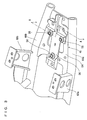
Fig. 2 is a perspective view, showing an example of rear frame. -
Fig. 3 is a perspective view, showing an example of electric charger supporting portion which connects a pair of second frame portions with each other, and a region surrounding the electric charger supporting portion. -
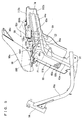
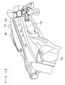
Fig. 4 is a perspective view, showing a rear frame, a battery and an electric charger as examples. -
Fig. 5 is an explanatory side view, showing the rear frame, the battery, the electric charger and an example of seat. -
Fig. 6 is a perspective view, showing an example of the electric charger mounted to the electric charger supporting portion. -
Fig. 7 is an explanatory sectional view, showing a section taken in lines A-A inFig. 3 . -
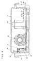
Fig. 8 is an explanatory drawing, showing an example of internal structure of the electric charger. -
Fig. 9 is a perspective view, showing an example of an electric cord storage tray, with a charger cord stored therein. -
Fig. 10 is a plan view, showing the electric cord storage tray, with the charger cord stored therein, as an example. -
Fig. 11 is a perspective view, showing an electric cord storage tray, a rear upper cover and a rear lower cover as examples. -
Fig. 12 is a perspective view, showing an example of heat dissipation opening provided in a rear lower cover. -
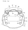
Fig. 13 is an explanatory sectional view for describing the heat dissipation openings provided in the rear lower cover. -
Fig. 14 is an explanatory drawing, showing a battery main body and a service plug of a battery as examples. -
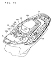
Fig. 15 is a perspective view, showing an electric cord storage tray and a plug cover as examples. -
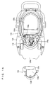
Fig. 16 is a plan view, showing the electric cord storage tray, with the plug cover removed, as an example. -
Fig. 17 is a perspective view, showing the electric cord storage tray, with the plug cover attached. -
Fig. 18 is a perspective view, showing the electric cord storage tray, with the plug cover removed. -
Fig. 19 is a perspective view, showing the electric cord storage tray and an example of battery main body, with the plug cover and the service plug removed. - Hereinafter, embodiments of the present invention will be described with reference to the drawings.
- It is noted that the terms right and left, front and rear, up and down as used in embodiments of the present invention are determined from the rider' s position on a
seat 98 of anelectric motorcycle 10, with the rider facing toward ahandlebar 24. - Referring to
Fig. 1 , anelectric motorcycle 10 according to an embodiment of the present invention includes amotorcycle body frame 12. Themotorcycle body frame 12 has ahead pipe 14; afront frame 16 extending from thehead pipe 14 in an obliquely rearward and downward direction; and arear frame 18 connected with a rear portion of thefront frame 16 and erected in an obliquely rearward and upward direction. - A steering
shaft 20 is pivotably inserted through thehead pipe 14. The steeringshaft 20 has an upper end mounted with ahandlebar supporting portion 22. Ahandlebar 24 is fixed to thehandlebar supporting portion 22. The steeringshaft 20 has a lower end mounted with afront fork 26. Afront wheel 28 is rotatably mounted to lower ends of thefront fork 26. In front of thehead pipe 14, a DC-DC converter 30 is provided in order to convert an output voltage from a battery 68 (to be described later) to a lower voltage (from 48 V to 12 V in this embodiment) for power supply to the motorcycle's system components. - The
front frame 16 includes a left-and-right pair ofdown tubes Fig. 2 ). Each of thedown tubes down tubes down tubes brackets brackets rear arm 34 via apivot shaft 17c so that therear arm 34 is pivotable. Therear arm 34 has arear end portion 34a, which incorporates anelectric motor 36 of an axial gap type for example. Theelectric motor 36 is connected with arear wheel 38 for driving thereby rotating therear wheel 38. Therear arm 34 incorporates adrive unit 40. Thedrive unit 40 is electrically connected with theelectric motor 36 and controls the rotating drive of theelectric motor 36. - Referring to
Fig. 2 , therear frame 18 includes a left-and-right pair offirst frame portions second frame portions charger supporting portion 46; a firstseat supporting portion 48; a secondseat supporting portion 50; and asuspension mounting portion 52. - The pair of
first frame portions down tubes second frame portions first frame portions first frame portions first frame portion 42a and thesecond frame portion 44a are made as a single piece by curving a frame into a generally V-shaped look, so a center region of the curved portion represents a connecting spot P1 of thefirst frame portion 42a and thesecond frame portion 44a. Likewise, thefirst frame portion 42b and thesecond frame portion 44b are made as a single piece by curving a frame into a generally V-shaped look, so a center region of the curved portion represents a connecting spot P2 of thefirst frame portion 42b and thesecond frame portion 44b. - Referring also to
Fig. 3 , the electriccharger supporting portion 46 is a platy portion which provides rectilinear connection between the pair ofsecond frame portions charger supporting portion 46 includes aplaty connecting portion 54 which connects rear end portions of thesecond frame portions insulation plate 56 attached onto the connectingportion 54. The connectingportion 54 and theinsulation plate 56 are fastened to each other by a plurality (three in this embodiment) offasteners 58 such as bolts. - Referring to
Fig. 2 andFig. 4 , the secondseat supporting portion 50 is at a more rearward position than the firstseat supporting portion 48, connects thesecond frame portions charger supporting portion 46, and supports theseat 98. The secondseat supporting portion 50 includes a pair oflower portions charger supporting portion 46, which are also substantially central region in the pair ofsecond frame portions upper portions lower portions platy connecting portion 62c which connects the pair ofupper portions seat 98. The pair oflower portions upper portions bolts 63. The pair ofupper portions upper portions portion 62c form a generally pi- (n-) shaped structure. - The first
seat supporting portion 48 includes apipe 65, which has a generally U-shaped look in a plan view, connects the pair ofsecond frame portions seat supporting portion 50, and projects in the forward direction; and a connecting portion 100 (to be described later), which is provided at a fore end portion of thepipe 65 and supports a front portion of theseat 98. Thepipe 65 has two ends, which are connected with thelower portions seat supporting portion 50 by connectingportions support pipes pipe 65 to a vicinity of the connecting spot P1 of thefirst frame portion 42a and thesecond frame portion 44a, and to a vicinity of the connecting spot P2 of thefirst frame portion 42b and thesecond frame portion 44b. Thesuspension mounting portion 52 is in a vicinity of an upper end portion (the connecting spot P1) of the left-sidefirst frame portion 42a. - Referring to
Fig. 4 andFig. 5 , between the pair offirst frame portions rear frame 18 described so far, abattery 68 is provided which supplies electric power to theelectric motor 36 and to the DC-DC converter 30. At a slightly lower position than a longitudinal center region of thefirst frame portions first frame portions battery holder 70 is provided. At a fore end region of the firstseat supporting portion 48, a rearward-facing hold-downportion 72 is provided. Thebattery 68 is supported by thebattery holder 70. Thebattery 68 has an upper surface held down by the hold-downportion 72. With the arrangement described above, thebattery 68 overlaps, in a side view, the connecting spot P1 (P2) of thefirst frame portion 42a (42b) and thesecond frame portion 44a (44b). Also, thebattery 68 is tilted rearward so that its upper front corner portion C1 is higher than its upper rear corner portion C2. Thebattery 68 includes a plurality ofcells 68a provided by lithium ion cells for example. Eachcell 68a is disposed so that itslongitudinal axis 68b lies in the motorcycle's width direction (left-right direction). The arrangement can prevent the motorcycle from having an excessively large length compared to arrangements where eachcell 68a is disposed so that itslongitudinal axis 68b lies in the motorcycle's fore-aft direction, even in cases where the battery is of an increased capacity. - Behind the
battery 68, a BMC (Battery Management Controller) 69 is provided. TheBMC 69 is electrically connected with thedrive unit 40, thebattery 68 and theelectric charger 74. - Referring also to
Fig. 6 andFig. 7 , theelectric charger 74 is mounted on theinsulation plate 56 of the electriccharger supporting portion 46, for charging thebattery 68. Theelectric charger 74 is disposed so that it partially lies beneath the secondseat supporting portion 50. Theelectric charger 74 has a bottom surface formed with a plurality (three in the present embodiment) of projectedportions 76 provided by generally prismatic bodies for example. Each projectedportion 76 is connected with theinsulation plate 56 by afastener 78 such as a bolt. As described above, theelectric charger 74 is disposed at a position which is beneath theseat 98 and above therear wheel 38. Theelectric charger 74 has its fore end F located at a more forward position than the rear end (corner portion C2) of the battery 68 (seeFig. 5 ) . Also, in a side view, theelectric charger 74 is located at a higher position than thesecond frame portions electric charger 74 above thesecond frame portions first frame portions electric charger 74 and than conventional arrangements. Further, the fore end F of theelectric charger 74 is at a lower position than the upper end (corner portion C1) of thebattery 68, and theelectric charger 74 is disposed at a forward tilting angle (seeFig. 5 ). - Referring to
Fig. 8 , theelectric charger 74 includes an upwardly openingcase 80 made of aluminum for example. Thecase 80 has a side surface formed with a plurality ofheat dissipation fins 81. Alid 82 which is made of resin for example, is attached to an upper surface of thecase 80. Thecase 80 incorporates anIC substrate 84. Aheat dissipation plate 86 contacting to an inner wall of thecase 80 is attached to theIC substrate 84, and atransistor 88 is provided in contact with theheat dissipation plate 86. Thetransistor 88 is urged onto theheat dissipation plate 86 by anurge member 90. Also, theIC substrate 84 has acoil 92, atransformer 94, etc. provided thereon. TheIC substrate 84 is potted in apotting agent 96 which is poured into thecase 80 to a level just enough to cover theIC substrate 84. - By pouring the
potting agent 96 as described to a level enough to cover theIC substrate 84 which is susceptible to vibrations, the arrangement can reduce the amount of use of thepotting agent 96 and keep theelectric charger 74 light while reducing unwanted influences from vibrations of therear frame 18. - Also, by providing the
heat dissipation plate 86 on an inner wall of thecase 80, the arrangement can improve heat dissipating capability together with the heat dissipation openings 114 (to be described later) which are provided in the rearlower cover 112a. Moreover, by urging thetransistor 88, which is a heat-generating component, onto theheat dissipation plate 86 with theurge member 90, the arrangement can further improve heat dissipating capability. - Referring to
Fig. 1 ,Fig. 5 andFig. 13 , theseat 98 includes a seatmain body 98a; a plurality ofprojections 98b provided in a lower surface of the seatmain body 98a; and acover 98c provided at a rear end portion of the seatmain body 98a. Referring also toFig. 4 andFig. 5 , the seatmain body 98a has a fore end portion attached to a vicinity of a fore-end portion of a lower surface of the firstseat supporting portion 48 via the connectingportion 100. Thus, theseat 98 is openable/closable (pivotable) around the connectingportion 100. When theseat 98 is closed, theprojections 98b have their flat bottom surfaces contacting onto an upper surface of the connectingportion 62c in the secondseat supporting portion 50, and keeps theseat 98 in position. Returning toFig. 1 , thesuspension mounting portion 52 and theswing arm 34 are connected with each other by asuspension 102. - Referring then to
Fig. 5 ,Fig. 9 andFig. 10 , an electriccord storage tray 104 is disposed above the firstseat supporting portion 48, the secondseat supporting portion 50 and theelectric charger 74. - The electric
cord storage tray 104 includes a traymain body 104a which is elongate in the fore-aft direction. The traymain body 104a has a fore end region formed as a forwardly uphillsloped portion 104b. The slopedportion 104b has two sides formed with a pair offitting portions fitting portions pipe 65 on respective sides of the motorcycle. Near thefitting portion 104c, a through-hole 104e is provided for acharging cord 106 to go out for connection to theelectric charger 74. A slightlycurved engager 104f is formed between thefitting portions charging cord 106 to engage with. The traymain body 104a has a rear region formed as an upwardly projectingprojection 104g. Theprojection 104g includes afront wall 104h; a left and aright side walls rear wall 104k; and aceiling plate 1041. Theprojection 104g is provided with a through-hole 104m at a position surrounded by thefront wall 104h and the left-and-right side walls upper portions seat supporting portion 50. When the pair ofupper portions hole 104m, the connectingportion 62c is exposed from the through-hole 104m. A nail-like clip tub 104n is erected in front of thefront wall 104h. Thefront wall 104h and theclip tub 104n are spaced from each other so that aplug 106a of thecharging cord 106 can be clipped and held in between. The traymain body 104a has its rear half region formed with a generally semielliptical outer wall 104o. - The
charging cord 106 is stored on the above-described electriccord storage tray 104, and therefore thecharging cord 106 is stored between theseat 98 and theelectric charger 74. When being stored, thecharging cord 106 is routed between the outer wall 104o and theprojection 104g, being wound around along theside wall 104i, therear wall 104k and theside wall 104j of theprojection 104g, and then the engager 104f, so that theplug 106a is caught between thefront wall 104h of theprojection 104g and theclip tub 104n. Agrip portion 107 is provided near the electriccord storage tray 104. - Referring to
Fig. 1 , afront panel 108 is attached to a front portion of thehead pipe 14, covering the DC-DC converter 30. Afront cover 110 is attached near thefront frame 16. A rearlower cover 112a and a rearupper cover 112b engaged therewith are provided near therear frame 18. - Referring to
Fig. 11 through Fig. 13 , along a left and a right side surfaces of theelectric charger 74, a plurality (five on each side in the present embodiment) ofheat dissipation openings 114 are provided in the rearlower cover 112a. Eachheat dissipation opening 114 is an elongate hole for example. - According to the
electric motorcycle 10 as described thus far, thefirst frame portion 42a (42b) is shorter than in conventional arrangement. The connecting spot P1 (P2) of thefirst frame portion 42a (42b) and thesecond frame portion 44a (44b) is at a lower position than theelectric charger 74, and overlaps thebattery 74 in a side view. Also, thesecond frame portion 44a (44b) is shorter than in conventional arrangements and extends below theelectric charger 74 in a rearward direction. Therefore, a total length of thefirst frame portion 42a (42b) and thesecond frame portion 44a (44b) is shorter than in conventional arrangement. With the above-described arrangement, theelectric charger 74 is supported by the electriccharger supporting portion 46 which provides rectilinear connection between the twosecond frame portions rear frame 18 which is shorter than conventional ones, and by using the electriccharger supporting portion 46 which provides rectilinear connection between thesecond frame portions front frame 16 and the rear frame 18 (seeFig. 2 andFig. 5 ), through thefirst frame portion 42a (42b), thesecond frame portion 44a (44b) and the electriccharger supporting portion 46, to theelectric charger 74; namely, a length of members (a route) from the connecting spot X1 (X2) of thefront frame 16 and therear frame 18 to theelectric charger 74, in comparison with conventional arrangements. Therefore, it is possible to reduce vibration which is transmitted from the connecting spot X1 (X2) via therear frame 18 to theelectric charger 74. Also, by connecting thesecond frame portions seat supporting portion 50, the arrangement provides rigid support to thesecond frame portions electric charger 74. Further, while the secondseat supporting portion 50 connects thesecond frame portions seat supporting portion 50 is located at a more forward position than the electriccharger supporting portion 46. In this arrangement, load concentration onto rear ends of thesecond frame portions second frame portions electric charger 74. As has been described, a combination of a plurality of structural characteristics including a shortenedrear frame 18; a rigidly supported pair ofsecond frame portions seat supporting portion 50; etc. leads to reduced vibration to theelectric charger 74. - The second
seat supporting portion 50 connects thesecond frame portions electric charger 74. In this arrangement, the secondseat supporting portion 50 is not an obstacle in disposing theelectric charger 74, and theelectric charger 74 can be disposed at a forward position. As a result, the electriccharger supporting portion 46, which supports theelectric charger 74, can also be at a forward position. The arrangement can shorten thesecond frame portions charger supporting portion 46. Therefore, it becomes possible to further shorten the length of members (the route) from the connecting spot X1 (X2) of thefront frame 16 and therear frame 18 to theelectric charger 74 and hence, to further reduce vibration which is transmitted to theelectric charger 74. - The
upper portion 62a of the secondseat supporting portion 50 is at least partially located on a more laterally inward side of the motorcycle than thelower portion 60a to which theupper portion 62a is connected. Likewise, theupper portion 62b is at least partially located on a more laterally inward side of the motorcycle than thelower portion 60b to which theupper portion 62b is connected. Therefore, when thecharging cord 106 is laid on the outer sides of theupper portions seat supporting portion 50, thecharging cord 106 can be stored smoothly without flipping. - Since the
electric charger 74 is disposed so that its fore end is located at a more forward position than the rear end of thebattery 68, the rear end of theelectric charger 74 is located accordingly at a forward position. Therefore, thesecond frame portions electric charger 74 can be shortened for further reduction of vibration which is transmitted to theelectric charger 74. - Since the first
seat supporting portion 48 and the secondseat supporting portion 50 are connected with each other by the connectingportions seat supporting portion 50 and also to thesecond frame portions electric charger 74. - The
charging cord 106 is stored between theseat 98 and theelectric charger 74. In this case, it is possible to provide a large storage space for thecharging cord 106. The space can easily accommodate a long (e.g. 2-meter) chargingcord 106. This also provides increased convenience for the motorcycle rider to perform charging operations. Also, the arrangement allows thecharging cord 106 to be stored at a small curvature, which extends life of thecharging cord 106. - The
battery 68 is disposed at a rearward tilt; the fore end F of theelectric charger 74 is located at a lower height than the upper end (corner portion C1) of thebattery 68; and theelectric charger 74 is disposed at a forward tile. Therefore, it is possible to provide a large storage space for thecharging cord 106 between theelectric charger 74 and theseat 98. - In storage, the
charging cord 106 is routed between the outer wall 104o and theprojection 104g in the electriccord storage tray 104. The arrangement provides easy storage of thecharging cord 106 without flipping. - Also, the
charging cord 106 is wound around, while being fitted into the engager 104f and therear wall 104k provided in the front and in the rear of the traymain body 104a respectively. The arrangement reduces flipping of thecharging cord 106, making it easy to store. - Further, since the
plug 106a is caught by thefront wall 104h of theprojection 104g and theclip tub 104n, flipping of thecharging cord 106 is reduced, making it easy to store thecharging cord 106. - The
electric charger 74 and thecharging cord 106 provided in theelectric motorcycle 10 allow for charging from any standard power source available, and therefore increase convenience. - The
insulation plate 56 placed between theelectric charger 74 and the connectingportion 54 provides insulation between theelectric charger 74 and thesecond frame portions - It should be noted here that with reference to
Fig. 4 ,Fig. 5 ,Fig. 14 andFig. 19 , thebattery 68 includes a batterymain body 116 which stores a plurality ofcells 68a; and aservice plug 118 which is attachable to and detachable from the batterymain body 116. Theservice plug 118 is used to establish a reliable, mechanical circuit breakage within thebattery 68. The batterymain body 116 has aplug receptacle 120 at a generally central region in its upper surface (seeFig. 19 ). As theservice plug 118 is attached to theplug receptacle 120, aconnection conductor 122 of theservice plug 118 is inserted intosockets 124 of the batterymain body 116, and circuit continuity is established within thebattery 68. On the other hand, removing theservice plug 118 from theplug receptacle 120 removes contact of theconnection conductor 122 of theservice plug 118 from thesockets 124 of the batterymain body 116, breaking the circuit continuity within thebattery 68. - Referring also to
Fig. 16 , when theservice plug 118 is attached to theplug receptacle 120 of the batterymain body 116, theservice plug 118 is at a generally central region of a motorcycle width (in the left-right direction) in a plan view; surrounded by the firstseat supporting portion 48 from three directions; and is ahead of theelectric charger 74 in a side view. - For improved access to the
service plug 118 as described above, the electriccord storage tray 104 may be replaced by an electriccord storage tray 126 and aplug cover 128, for example, as shown inFig. 15 andFig. 16 . - The electric
cord storage tray 126 is disposed above the firstseat supporting portion 48, the secondseat supporting portion 50, thebattery 68 and theelectric charger 74. The electriccord storage tray 126 has a through-hole 126a at a position corresponding to theservice plug 118 of thebattery 68. The electriccord storage tray 126 includes afore tray portion 126b which is provided above the firstseat supporting portion 48; arear tray portion 126c which is provided above the secondseat supporting portion 50; and a generally semiellipticalouter wall 126d which is provided along therear tray portion 126c. - The
plug cover 128 includes a covermain body 128a; anengager 128b erected from a fore portion of the covermain body 128a and curving sideways; and aplaty portion 128c provided on the covermain body 128a. Theplug cover 128 is attachable to and detachable from the electriccord storage tray 126, capable of closing the through-hole 126a, and can be disposed above theservice plug 118 of thebattery 68. When theplug cover 128 is attached, theplug cover 128 is positioned so that the engager 128b is at a fore position. - When storing a
charging cord 130, thecharging cord 130 is wound around therear tray portion 126c and the engager 128b, and theplug 130a is stored between thefore tray portion 126b and therear tray portion 126c. - When using the electric
cord storage tray 126 and theplug cover 128 as described, access to theservice plug 118 is made as follows: - First, under a state shown in
Fig. 17 , the engager 128b of theplug cover 128 is pulled by hand to pull up and remove theplug cover 128. As shown inFig. 18 , the removal exposes theservice plug 118 which is beneath theplug cover 128. Then, access can be made to theservice plug 118 from above, for removal of theservice plug 118 from the batterymain body 116 as shown inFig. 19 . - By using the electric
cord storage tray 126 and theplug cover 128 as described, theservice plug 118 is stored without being exposed to the outside during normal use of the motorcycle. Meanwhile, theservice plug 118 is easily accessible, being located at a generally central region of the motorcycle width (in the left-right direction) in a plan view, and in an upper surface of batterymain body 116. Thus, simple removal of theplug cover 128 provides easy access from above to theservice plug 118. - Also, the
service plug 118 is at a generally central region in the upper surface of the rearward-tilted batterymain body 116. Therefore, the batterymain body 116 with theservice plug 118 attached thereto does not give an additional height to thebattery 68, so it is possible to provide a space above thebattery 68. - Further, the
plug receptacle 120 is below theseat 98. Therefore, even if theplug cover 128 is removed and theservice plug 118 is removed from the batterymain body 116, theplug receptacle 120 can be covered by simply flipping down theseat 98, and this prevents debris and other foreign objects from entering the batterymain body 116 through theplug receptacle 120. - It should be noted here that in the embodiment described above, the pair of
second frame portions first frame portions second frame portions - Also, in the embodiment described above, the
first frame portion 42a and thesecond frame portion 44a are a single frame which is curved into a generally V-shaped look. However, the present invention is not limited to these. Thefirst frame portion 42a and thesecond frame portion 44a may be formed by bending a single frame. In this case, the bent portion represents the connecting spot P1 of thefirst frame portion 42a and thesecond frame portion 44a. Also, thefirst frame portion 42a and thesecond frame portion 44a may be formed as individual frames and then connected with each other by welding for example. The same applies to thefirst frame portion 42b and thesecond frame portion 44b. - In the embodiment described above, the pair of
upper portions sheet supporting portion 50 increasingly come closer to each other at their higher positions. However, the present invention is not limited to this. It is preferable that theupper portion 62a is at least partially located on a more laterally inward side of the motorcycle than thelower portion 60a to which theupper portion 62a is connected. Likewise, it is preferable that theupper portion 62b is at least partially located on a more laterally inward side of the motorcycle than thelower portion 60b to which theupper portion 62b is connected. - It is preferable that the foot rests 32 are disposed at a position which is more forward and lower than part of the
seat 98. - The electric
charger supporting portion 46 may only be connected with one of thesecond frame portions - It is preferable that the second
seat supporting portion 50 has at least part of it located at a more forward position than the electriccharger supporting portion 46. - The present invention being thus far described in terms of preferred embodiments, it is obvious that these may be varied in many ways within the scope and the spirit of the present invention. The scope of the present invention is only limited by the accompanied claims.
-
- 10
- Electric motorcycle
- 12
- Motorcycle body frame
- 16
- Front frame
- 18
- Rear frame
- 32
- Foot rest
- 34
- Rear arm
- 36
- Electric motor
- 38
- Rear wheel
- 42a, 42b
- First frame portions
- 44a, 44b
- Second frame portions
- 46
- Electric charger supporting portion
- 48
- First seat supporting portion
- 50
- Second seat supporting portion
- 52
- Suspension mounting portion
- 54, 62c, 64a, 64b
- Connecting portions
- 56
- Insulation plate
- 60a, 60b
- Lower portions
- 62a, 62b
- Upper portions
- 68
- Battery
- 70
- Battery holder
- 72
- Hold-down portion
- 74
- Electric charger
- 98
- Seat
- 104, 126
- Electric cord storage trays
- 106, 130
- Charging cords
- 112a
- Rear upper cover
- 112b
- Rear lower cover
- 114
- Heat dissipation opening
- 116
- Battery main body
- 118
- Service plug
- 120
- Plug receptacle
- 126a
- Through-hole
- 128
- Plug cover
- C1
- Corner portion (upper end) of battery
- C2
- Corner portion (rear end) of battery
- F
- Fore end of electric charger
- P1, P2
- Connecting spot of first frame portion and second frame portion
- X1, X2
- Connecting spot of front frame and rear frame
Claims (7)
- An electric motorcycle comprising:a motorcycle body frame including a rear frame;a seat supported by the rear frame, for a rider to sit on;a foot rest disposed at a more forward and lower position than part of the seat and supported by the motorcycle body frame;a rear arm having a fore end portion connected with the motorcycle body frame;an electric motor provided in the rear arm;a rear wheel supported at a rear end portion of the rear arm and driven by the electric motor;a battery for supplying electric power to the electric motor; andan electric charger disposed below the seat, above the rear wheel for charging the battery;wherein the rear frame includes: a left-and-right pair of first frame portions extending in an obliquely upward and rearward direction, from a more rearward position than the foot rest; a left-and-right pair of second frame portions connected with the pair of first frame portions at a lower position than the electric charger and extending rearward below the electric charger; an electric charger supporting portion provided in the second frame portions and supporting the electric charger; a first seat supporting portion supporting a fore portion of the seat; and a second seat supporting portion disposed at a more rearward position than the first seat supporting portion, connecting the pair of second frame portions with each other and supporting the seat; andwherein the battery is provided between the pair of first frame portions so as to overlap connecting spots of the first frame portions and the second frame portions in a side view; at least part of the second seat supporting portion being located at a more forward position than the electric charger supporting portion.
- The electric motorcycle according to Claim 1, wherein the second seat supporting portion connects the pair of second frame portions with each other while straddling the electric charger.
- The electric motorcycle according to Claim 2, wherein the second seat supporting portion includes a pair of lower portions connected with the pair of second frame portions, and a pair of upper portions connected with the pair of lower portions and located between the pair of lower portions and the seat; each of the upper portions being at least partially located on a more laterally inward side of the motorcycle than the lower portion to which said upper portion is connected.
- The electric motorcycle according to one of Claims 1 to 3, wherein the electric charger has a fore end located at a more forward position than a rear end of the battery.
- The electric motorcycle according to one of Claims 1 to 4, further comprising a connecting portion which connects the first seat supporting portion and the second seat supporting portion with each other.
- The electric motorcycle according to one of Claims 1 to 5, further comprising a charging cord connected with the electric charger and stored between the seat and the electric charger.
- The electric motorcycle according to Claim 6, wherein the battery is disposed at a rearward tilt, the electric charger having its fore end located at a lower position than an upper end of the battery, the electric charger being disposed at a forward tilt.
Priority Applications (1)
| Application Number | Priority Date | Filing Date | Title |
|---|---|---|---|
| EP14164810.5A EP2783965A1 (en) | 2009-09-30 | 2010-09-30 | Electric motorcycle |
Applications Claiming Priority (2)
| Application Number | Priority Date | Filing Date | Title |
|---|---|---|---|
| JP2009229053 | 2009-09-30 | ||
| JP2009294090A JP5443152B2 (en) | 2009-09-30 | 2009-12-25 | Electric motorcycle |
Related Child Applications (2)
| Application Number | Title | Priority Date | Filing Date |
|---|---|---|---|
| EP14164810.5A Division EP2783965A1 (en) | 2009-09-30 | 2010-09-30 | Electric motorcycle |
| EP14164810.5A Previously-Filed-Application EP2783965A1 (en) | 2009-09-30 | 2010-09-30 | Electric motorcycle |
Publications (3)
| Publication Number | Publication Date |
|---|---|
| EP2305548A2 true EP2305548A2 (en) | 2011-04-06 |
| EP2305548A3 EP2305548A3 (en) | 2013-01-23 |
| EP2305548B1 EP2305548B1 (en) | 2014-04-23 |
Family
ID=43413971
Family Applications (2)
| Application Number | Title | Priority Date | Filing Date |
|---|---|---|---|
| EP10183905.8A Not-in-force EP2305548B1 (en) | 2009-09-30 | 2010-09-30 | Electric motorcycle |
| EP14164810.5A Withdrawn EP2783965A1 (en) | 2009-09-30 | 2010-09-30 | Electric motorcycle |
Family Applications After (1)
| Application Number | Title | Priority Date | Filing Date |
|---|---|---|---|
| EP14164810.5A Withdrawn EP2783965A1 (en) | 2009-09-30 | 2010-09-30 | Electric motorcycle |
Country Status (5)
| Country | Link |
|---|---|
| EP (2) | EP2305548B1 (en) |
| JP (1) | JP5443152B2 (en) |
| CN (1) | CN102030062A (en) |
| ES (1) | ES2470667T3 (en) |
| TW (1) | TWI417219B (en) |
Cited By (4)
| Publication number | Priority date | Publication date | Assignee | Title |
|---|---|---|---|---|
| CN103448839A (en) * | 2012-05-29 | 2013-12-18 | 雅马哈发动机株式会社 | Motor vehicle cushion structure and cushion hinge thereof |
| WO2019086449A1 (en) | 2017-11-02 | 2019-05-09 | Piaggio & C. S.P.A. | Electric drive motorcycle |
| DE102019115466A1 (en) * | 2019-06-07 | 2020-12-10 | Bayerische Motoren Werke Aktiengesellschaft | Motorcycle and method of operating a motorcycle |
| US11390350B2 (en) * | 2018-08-07 | 2022-07-19 | Harley-Davidson Motor Company Group, LLC | Seat caddy for charging cable |
Families Citing this family (7)
| Publication number | Priority date | Publication date | Assignee | Title |
|---|---|---|---|---|
| CN103507910B (en) * | 2013-10-28 | 2016-01-27 | 孙剑山 | The shockproof heat abstractor of vehicle-mounted electrical vehicle charger |
| ITUB20151030A1 (en) * | 2015-05-29 | 2016-11-29 | Selle Royal Spa | ERGONOMIC SEAT FOR A VEHICLE |
| JP7097979B2 (en) * | 2018-08-28 | 2022-07-08 | 本田技研工業株式会社 | Saddle-type vehicle |
| CN217508298U (en) * | 2019-09-27 | 2022-09-27 | 本田技研工业株式会社 | Charger for mobile storage battery |
| ES1291268Y (en) | 2019-10-31 | 2022-08-30 | Zapp Electric Vehicles Ltd | ELECTRIC MOTORCYCLE |
| JP7347167B2 (en) * | 2019-11-29 | 2023-09-20 | スズキ株式会社 | saddle type vehicle |
| CN212022872U (en) * | 2020-04-17 | 2020-11-27 | 浙江欧凯车业有限公司 | Intelligent safety frame capable of easily replacing and protecting battery |
Citations (1)
| Publication number | Priority date | Publication date | Assignee | Title |
|---|---|---|---|---|
| WO2004069638A1 (en) | 2003-02-07 | 2004-08-19 | Yamaha Hatsudoki Kabushiki Kaisha | Electrically powered motorcycle |
Family Cites Families (11)
| Publication number | Priority date | Publication date | Assignee | Title |
|---|---|---|---|---|
| JPH06278667A (en) * | 1993-01-26 | 1994-10-04 | Honda Motor Co Ltd | Electric vehicle |
| JP3324192B2 (en) * | 1993-04-09 | 2002-09-17 | スズキ株式会社 | Electric scooter type vehicle |
| JP3347433B2 (en) * | 1993-10-19 | 2002-11-20 | 本田技研工業株式会社 | Electric vehicle charging cord storage structure |
| CN2353645Y (en) * | 1999-01-24 | 1999-12-15 | 吴希民 | Frame of electric vehicle |
| JP4454188B2 (en) * | 2001-06-25 | 2010-04-21 | 本田技研工業株式会社 | Battery device for electric vehicle |
| US6691813B2 (en) * | 2002-05-16 | 2004-02-17 | The Electric Cycle Company | Frames for electric motor driven cycles |
| JP4274759B2 (en) * | 2002-08-16 | 2009-06-10 | ヤマハ発動機株式会社 | Electric motorcycle |
| JP2004187329A (en) * | 2002-10-11 | 2004-07-02 | Yamaha Motor Co Ltd | Electrically driven vehicle |
| US7210550B2 (en) * | 2003-05-30 | 2007-05-01 | Honda Motor Co., Ltd. | Under-seat structure for a motorcycle |
| JP2007015641A (en) * | 2005-07-11 | 2007-01-25 | Yamaha Motor Co Ltd | Power-assisted bicycle |
| CN101486368A (en) * | 2009-02-25 | 2009-07-22 | 无锡亿威车辆科技有限公司 | Electric motor vehicle |
-
2009
- 2009-12-25 JP JP2009294090A patent/JP5443152B2/en not_active Expired - Fee Related
-
2010
- 2010-09-28 TW TW099132851A patent/TWI417219B/en not_active IP Right Cessation
- 2010-09-30 CN CN2010105039828A patent/CN102030062A/en active Pending
- 2010-09-30 EP EP10183905.8A patent/EP2305548B1/en not_active Not-in-force
- 2010-09-30 EP EP14164810.5A patent/EP2783965A1/en not_active Withdrawn
- 2010-09-30 ES ES10183905.8T patent/ES2470667T3/en active Active
Patent Citations (1)
| Publication number | Priority date | Publication date | Assignee | Title |
|---|---|---|---|---|
| WO2004069638A1 (en) | 2003-02-07 | 2004-08-19 | Yamaha Hatsudoki Kabushiki Kaisha | Electrically powered motorcycle |
Cited By (6)
| Publication number | Priority date | Publication date | Assignee | Title |
|---|---|---|---|---|
| CN103448839A (en) * | 2012-05-29 | 2013-12-18 | 雅马哈发动机株式会社 | Motor vehicle cushion structure and cushion hinge thereof |
| CN103448839B (en) * | 2012-05-29 | 2016-03-30 | 雅马哈发动机株式会社 | Engine cushion structure and cushion hinge thereof |
| WO2019086449A1 (en) | 2017-11-02 | 2019-05-09 | Piaggio & C. S.P.A. | Electric drive motorcycle |
| US11319014B2 (en) | 2017-11-02 | 2022-05-03 | Piaggio & C. S.P.A. | Electric drive motorcycle |
| US11390350B2 (en) * | 2018-08-07 | 2022-07-19 | Harley-Davidson Motor Company Group, LLC | Seat caddy for charging cable |
| DE102019115466A1 (en) * | 2019-06-07 | 2020-12-10 | Bayerische Motoren Werke Aktiengesellschaft | Motorcycle and method of operating a motorcycle |
Also Published As
| Publication number | Publication date |
|---|---|
| CN102030062A (en) | 2011-04-27 |
| EP2305548B1 (en) | 2014-04-23 |
| EP2783965A1 (en) | 2014-10-01 |
| TWI417219B (en) | 2013-12-01 |
| ES2470667T3 (en) | 2014-06-24 |
| EP2305548A3 (en) | 2013-01-23 |
| JP2011093510A (en) | 2011-05-12 |
| TW201134720A (en) | 2011-10-16 |
| JP5443152B2 (en) | 2014-03-19 |
Similar Documents
| Publication | Publication Date | Title |
|---|---|---|
| EP2305548B1 (en) | Electric motorcycle | |
| US7210548B2 (en) | Electric powered vehicle | |
| JP6284746B2 (en) | Straddle-type electric vehicle | |
| JP5605376B2 (en) | Electric motorcycle | |
| JP6245946B2 (en) | Battery and saddle riding type electric vehicle equipped with the same | |
| JP5741592B2 (en) | Electric motorcycle | |
| US9669898B2 (en) | Electric vehicle | |
| US20120111651A1 (en) | Saddle-type electric vehicle | |
| JP2015089754A (en) | Saddle-riding type electric vehicle | |
| TW201012669A (en) | Electric motorcycle | |
| JP5632789B2 (en) | Saddle riding | |
| JP5594229B2 (en) | Scooter type vehicle | |
| JP5588825B2 (en) | Electric motorcycle | |
| JP5764644B2 (en) | Electric motorcycle | |
| JP2010076531A (en) | Battery arrangement structure in motor-driven vehicle | |
| JP2012201318A (en) | Battery holding device of vehicle | |
| JP2011031818A (en) | Motorcycle | |
| EP3689724B1 (en) | Hybrid vehicle | |
| CN112874675A (en) | Straddle-type vehicle | |
| JP7285941B2 (en) | portable battery charger | |
| CN112874680B (en) | Straddle-type vehicle | |
| JP7367496B2 (en) | saddle type vehicle | |
| EP4012827A1 (en) | Battery | |
| TWI777998B (en) | A vehicle with low-slung power unit and a frame thereof | |
| JP2023116134A (en) | Electric straddle-type vehicle |
Legal Events
| Date | Code | Title | Description |
|---|---|---|---|
| PUAI | Public reference made under article 153(3) epc to a published international application that has entered the european phase |
Free format text: ORIGINAL CODE: 0009012 |
|
| AK | Designated contracting states |
Kind code of ref document: A2 Designated state(s): AL AT BE BG CH CY CZ DE DK EE ES FI FR GB GR HR HU IE IS IT LI LT LU LV MC MK MT NL NO PL PT RO SE SI SK SM TR |
|
| AX | Request for extension of the european patent |
Extension state: BA ME RS |
|
| PUAL | Search report despatched |
Free format text: ORIGINAL CODE: 0009013 |
|
| AK | Designated contracting states |
Kind code of ref document: A3 Designated state(s): AL AT BE BG CH CY CZ DE DK EE ES FI FR GB GR HR HU IE IS IT LI LT LU LV MC MK MT NL NO PL PT RO SE SI SK SM TR |
|
| AX | Request for extension of the european patent |
Extension state: BA ME RS |
|
| RIC1 | Information provided on ipc code assigned before grant |
Ipc: B62K 11/10 20060101AFI20121214BHEP |
|
| 17P | Request for examination filed |
Effective date: 20130722 |
|
| RBV | Designated contracting states (corrected) |
Designated state(s): AL AT BE BG CH CY CZ DE DK EE ES FI FR GB GR HR HU IE IS IT LI LT LU LV MC MK MT NL NO PL PT RO SE SI SK SM TR |
|
| GRAP | Despatch of communication of intention to grant a patent |
Free format text: ORIGINAL CODE: EPIDOSNIGR1 |
|
| INTG | Intention to grant announced |
Effective date: 20131031 |
|
| GRAS | Grant fee paid |
Free format text: ORIGINAL CODE: EPIDOSNIGR3 |
|
| GRAA | (expected) grant |
Free format text: ORIGINAL CODE: 0009210 |
|
| AK | Designated contracting states |
Kind code of ref document: B1 Designated state(s): AL AT BE BG CH CY CZ DE DK EE ES FI FR GB GR HR HU IE IS IT LI LT LU LV MC MK MT NL NO PL PT RO SE SI SK SM TR |
|
| REG | Reference to a national code |
Ref country code: GB Ref legal event code: FG4D |
|
| REG | Reference to a national code |
Ref country code: CH Ref legal event code: EP |
|
| REG | Reference to a national code |
Ref country code: AT Ref legal event code: REF Ref document number: 663655 Country of ref document: AT Kind code of ref document: T Effective date: 20140515 |
|
| REG | Reference to a national code |
Ref country code: IE Ref legal event code: FG4D |
|
| REG | Reference to a national code |
Ref country code: DE Ref legal event code: R096 Ref document number: 602010015328 Country of ref document: DE Effective date: 20140528 |
|
| REG | Reference to a national code |
Ref country code: NL Ref legal event code: T3 |
|
| REG | Reference to a national code |
Ref country code: ES Ref legal event code: FG2A Ref document number: 2470667 Country of ref document: ES Kind code of ref document: T3 Effective date: 20140624 |
|
| REG | Reference to a national code |
Ref country code: AT Ref legal event code: MK05 Ref document number: 663655 Country of ref document: AT Kind code of ref document: T Effective date: 20140423 |
|
| REG | Reference to a national code |
Ref country code: LT Ref legal event code: MG4D |
|
| PG25 | Lapsed in a contracting state [announced via postgrant information from national office to epo] |
Ref country code: FI Free format text: LAPSE BECAUSE OF FAILURE TO SUBMIT A TRANSLATION OF THE DESCRIPTION OR TO PAY THE FEE WITHIN THE PRESCRIBED TIME-LIMIT Effective date: 20140423 Ref country code: IS Free format text: LAPSE BECAUSE OF FAILURE TO SUBMIT A TRANSLATION OF THE DESCRIPTION OR TO PAY THE FEE WITHIN THE PRESCRIBED TIME-LIMIT Effective date: 20140823 Ref country code: NO Free format text: LAPSE BECAUSE OF FAILURE TO SUBMIT A TRANSLATION OF THE DESCRIPTION OR TO PAY THE FEE WITHIN THE PRESCRIBED TIME-LIMIT Effective date: 20140723 Ref country code: CY Free format text: LAPSE BECAUSE OF FAILURE TO SUBMIT A TRANSLATION OF THE DESCRIPTION OR TO PAY THE FEE WITHIN THE PRESCRIBED TIME-LIMIT Effective date: 20140423 Ref country code: LT Free format text: LAPSE BECAUSE OF FAILURE TO SUBMIT A TRANSLATION OF THE DESCRIPTION OR TO PAY THE FEE WITHIN THE PRESCRIBED TIME-LIMIT Effective date: 20140423 Ref country code: BG Free format text: LAPSE BECAUSE OF FAILURE TO SUBMIT A TRANSLATION OF THE DESCRIPTION OR TO PAY THE FEE WITHIN THE PRESCRIBED TIME-LIMIT Effective date: 20140723 Ref country code: GR Free format text: LAPSE BECAUSE OF FAILURE TO SUBMIT A TRANSLATION OF THE DESCRIPTION OR TO PAY THE FEE WITHIN THE PRESCRIBED TIME-LIMIT Effective date: 20140724 |
|
| PG25 | Lapsed in a contracting state [announced via postgrant information from national office to epo] |
Ref country code: PL Free format text: LAPSE BECAUSE OF FAILURE TO SUBMIT A TRANSLATION OF THE DESCRIPTION OR TO PAY THE FEE WITHIN THE PRESCRIBED TIME-LIMIT Effective date: 20140423 Ref country code: LV Free format text: LAPSE BECAUSE OF FAILURE TO SUBMIT A TRANSLATION OF THE DESCRIPTION OR TO PAY THE FEE WITHIN THE PRESCRIBED TIME-LIMIT Effective date: 20140423 Ref country code: AT Free format text: LAPSE BECAUSE OF FAILURE TO SUBMIT A TRANSLATION OF THE DESCRIPTION OR TO PAY THE FEE WITHIN THE PRESCRIBED TIME-LIMIT Effective date: 20140423 Ref country code: SE Free format text: LAPSE BECAUSE OF FAILURE TO SUBMIT A TRANSLATION OF THE DESCRIPTION OR TO PAY THE FEE WITHIN THE PRESCRIBED TIME-LIMIT Effective date: 20140423 Ref country code: HR Free format text: LAPSE BECAUSE OF FAILURE TO SUBMIT A TRANSLATION OF THE DESCRIPTION OR TO PAY THE FEE WITHIN THE PRESCRIBED TIME-LIMIT Effective date: 20140423 |
|
| PG25 | Lapsed in a contracting state [announced via postgrant information from national office to epo] |
Ref country code: PT Free format text: LAPSE BECAUSE OF FAILURE TO SUBMIT A TRANSLATION OF THE DESCRIPTION OR TO PAY THE FEE WITHIN THE PRESCRIBED TIME-LIMIT Effective date: 20140825 |
|
| REG | Reference to a national code |
Ref country code: DE Ref legal event code: R097 Ref document number: 602010015328 Country of ref document: DE |
|
| PG25 | Lapsed in a contracting state [announced via postgrant information from national office to epo] |
Ref country code: EE Free format text: LAPSE BECAUSE OF FAILURE TO SUBMIT A TRANSLATION OF THE DESCRIPTION OR TO PAY THE FEE WITHIN THE PRESCRIBED TIME-LIMIT Effective date: 20140423 Ref country code: BE Free format text: LAPSE BECAUSE OF FAILURE TO SUBMIT A TRANSLATION OF THE DESCRIPTION OR TO PAY THE FEE WITHIN THE PRESCRIBED TIME-LIMIT Effective date: 20140423 Ref country code: SK Free format text: LAPSE BECAUSE OF FAILURE TO SUBMIT A TRANSLATION OF THE DESCRIPTION OR TO PAY THE FEE WITHIN THE PRESCRIBED TIME-LIMIT Effective date: 20140423 Ref country code: CZ Free format text: LAPSE BECAUSE OF FAILURE TO SUBMIT A TRANSLATION OF THE DESCRIPTION OR TO PAY THE FEE WITHIN THE PRESCRIBED TIME-LIMIT Effective date: 20140423 Ref country code: RO Free format text: LAPSE BECAUSE OF FAILURE TO SUBMIT A TRANSLATION OF THE DESCRIPTION OR TO PAY THE FEE WITHIN THE PRESCRIBED TIME-LIMIT Effective date: 20140423 Ref country code: DK Free format text: LAPSE BECAUSE OF FAILURE TO SUBMIT A TRANSLATION OF THE DESCRIPTION OR TO PAY THE FEE WITHIN THE PRESCRIBED TIME-LIMIT Effective date: 20140423 |
|
| PLBE | No opposition filed within time limit |
Free format text: ORIGINAL CODE: 0009261 |
|
| STAA | Information on the status of an ep patent application or granted ep patent |
Free format text: STATUS: NO OPPOSITION FILED WITHIN TIME LIMIT |
|
| 26N | No opposition filed |
Effective date: 20150126 |
|
| PG25 | Lapsed in a contracting state [announced via postgrant information from national office to epo] |
Ref country code: LU Free format text: LAPSE BECAUSE OF FAILURE TO SUBMIT A TRANSLATION OF THE DESCRIPTION OR TO PAY THE FEE WITHIN THE PRESCRIBED TIME-LIMIT Effective date: 20140930 Ref country code: MC Free format text: LAPSE BECAUSE OF FAILURE TO SUBMIT A TRANSLATION OF THE DESCRIPTION OR TO PAY THE FEE WITHIN THE PRESCRIBED TIME-LIMIT Effective date: 20140423 |
|
| REG | Reference to a national code |
Ref country code: CH Ref legal event code: PL |
|
| REG | Reference to a national code |
Ref country code: DE Ref legal event code: R097 Ref document number: 602010015328 Country of ref document: DE Effective date: 20150126 |
|
| GBPC | Gb: european patent ceased through non-payment of renewal fee |
Effective date: 20140930 |
|
| REG | Reference to a national code |
Ref country code: IE Ref legal event code: MM4A |
|
| PG25 | Lapsed in a contracting state [announced via postgrant information from national office to epo] |
Ref country code: LI Free format text: LAPSE BECAUSE OF NON-PAYMENT OF DUE FEES Effective date: 20140930 Ref country code: GB Free format text: LAPSE BECAUSE OF NON-PAYMENT OF DUE FEES Effective date: 20140930 Ref country code: CH Free format text: LAPSE BECAUSE OF NON-PAYMENT OF DUE FEES Effective date: 20140930 Ref country code: SI Free format text: LAPSE BECAUSE OF FAILURE TO SUBMIT A TRANSLATION OF THE DESCRIPTION OR TO PAY THE FEE WITHIN THE PRESCRIBED TIME-LIMIT Effective date: 20140423 |
|
| PG25 | Lapsed in a contracting state [announced via postgrant information from national office to epo] |
Ref country code: IE Free format text: LAPSE BECAUSE OF NON-PAYMENT OF DUE FEES Effective date: 20140930 |
|
| PG25 | Lapsed in a contracting state [announced via postgrant information from national office to epo] |
Ref country code: SM Free format text: LAPSE BECAUSE OF FAILURE TO SUBMIT A TRANSLATION OF THE DESCRIPTION OR TO PAY THE FEE WITHIN THE PRESCRIBED TIME-LIMIT Effective date: 20140423 |
|
| PG25 | Lapsed in a contracting state [announced via postgrant information from national office to epo] |
Ref country code: MT Free format text: LAPSE BECAUSE OF FAILURE TO SUBMIT A TRANSLATION OF THE DESCRIPTION OR TO PAY THE FEE WITHIN THE PRESCRIBED TIME-LIMIT Effective date: 20140423 |
|
| PG25 | Lapsed in a contracting state [announced via postgrant information from national office to epo] |
Ref country code: TR Free format text: LAPSE BECAUSE OF FAILURE TO SUBMIT A TRANSLATION OF THE DESCRIPTION OR TO PAY THE FEE WITHIN THE PRESCRIBED TIME-LIMIT Effective date: 20140423 Ref country code: HU Free format text: LAPSE BECAUSE OF FAILURE TO SUBMIT A TRANSLATION OF THE DESCRIPTION OR TO PAY THE FEE WITHIN THE PRESCRIBED TIME-LIMIT; INVALID AB INITIO Effective date: 20100930 |
|
| REG | Reference to a national code |
Ref country code: FR Ref legal event code: PLFP Year of fee payment: 7 |
|
| PGFP | Annual fee paid to national office [announced via postgrant information from national office to epo] |
Ref country code: NL Payment date: 20160920 Year of fee payment: 7 Ref country code: DE Payment date: 20160921 Year of fee payment: 7 |
|
| PGFP | Annual fee paid to national office [announced via postgrant information from national office to epo] |
Ref country code: FR Payment date: 20160921 Year of fee payment: 7 |
|
| PGFP | Annual fee paid to national office [announced via postgrant information from national office to epo] |
Ref country code: ES Payment date: 20160916 Year of fee payment: 7 |
|
| PGFP | Annual fee paid to national office [announced via postgrant information from national office to epo] |
Ref country code: IT Payment date: 20160922 Year of fee payment: 7 |
|
| REG | Reference to a national code |
Ref country code: DE Ref legal event code: R119 Ref document number: 602010015328 Country of ref document: DE |
|
| REG | Reference to a national code |
Ref country code: NL Ref legal event code: MM Effective date: 20171001 |
|
| PG25 | Lapsed in a contracting state [announced via postgrant information from national office to epo] |
Ref country code: NL Free format text: LAPSE BECAUSE OF NON-PAYMENT OF DUE FEES Effective date: 20171001 Ref country code: MK Free format text: LAPSE BECAUSE OF FAILURE TO SUBMIT A TRANSLATION OF THE DESCRIPTION OR TO PAY THE FEE WITHIN THE PRESCRIBED TIME-LIMIT Effective date: 20140423 |
|
| REG | Reference to a national code |
Ref country code: FR Ref legal event code: ST Effective date: 20180531 |
|
| PG25 | Lapsed in a contracting state [announced via postgrant information from national office to epo] |
Ref country code: DE Free format text: LAPSE BECAUSE OF NON-PAYMENT OF DUE FEES Effective date: 20180404 |
|
| PG25 | Lapsed in a contracting state [announced via postgrant information from national office to epo] |
Ref country code: FR Free format text: LAPSE BECAUSE OF NON-PAYMENT OF DUE FEES Effective date: 20171002 Ref country code: IT Free format text: LAPSE BECAUSE OF NON-PAYMENT OF DUE FEES Effective date: 20170930 |
|
| REG | Reference to a national code |
Ref country code: ES Ref legal event code: FD2A Effective date: 20181017 |
|
| PG25 | Lapsed in a contracting state [announced via postgrant information from national office to epo] |
Ref country code: AL Free format text: LAPSE BECAUSE OF FAILURE TO SUBMIT A TRANSLATION OF THE DESCRIPTION OR TO PAY THE FEE WITHIN THE PRESCRIBED TIME-LIMIT Effective date: 20140423 |
|
| PG25 | Lapsed in a contracting state [announced via postgrant information from national office to epo] |
Ref country code: ES Free format text: LAPSE BECAUSE OF NON-PAYMENT OF DUE FEES Effective date: 20171001 |