EP2305517B1 - Vehicle ceiling structure - Google Patents
Vehicle ceiling structure Download PDFInfo
- Publication number
- EP2305517B1 EP2305517B1 EP09800250A EP09800250A EP2305517B1 EP 2305517 B1 EP2305517 B1 EP 2305517B1 EP 09800250 A EP09800250 A EP 09800250A EP 09800250 A EP09800250 A EP 09800250A EP 2305517 B1 EP2305517 B1 EP 2305517B1
- Authority
- EP
- European Patent Office
- Prior art keywords
- segmented
- rib
- protrusion
- segmented rib
- ceiling member
- Prior art date
- Legal status (The legal status is an assumption and is not a legal conclusion. Google has not performed a legal analysis and makes no representation as to the accuracy of the status listed.)
- Not-in-force
Links
- 230000003014 reinforcing effect Effects 0.000 claims description 71
- 229920005989 resin Polymers 0.000 claims description 24
- 239000011347 resin Substances 0.000 claims description 24
- 239000004831 Hot glue Substances 0.000 claims description 15
- 239000011358 absorbing material Substances 0.000 claims description 5
- 239000000853 adhesive Substances 0.000 description 13
- 230000001070 adhesive effect Effects 0.000 description 13
- 230000008602 contraction Effects 0.000 description 13
- 239000004743 Polypropylene Substances 0.000 description 6
- 238000005452 bending Methods 0.000 description 6
- 230000037303 wrinkles Effects 0.000 description 6
- 229920000122 acrylonitrile butadiene styrene Polymers 0.000 description 5
- 238000010586 diagram Methods 0.000 description 5
- 230000008878 coupling Effects 0.000 description 4
- 238000010168 coupling process Methods 0.000 description 4
- 238000005859 coupling reaction Methods 0.000 description 4
- 239000000463 material Substances 0.000 description 4
- 238000010521 absorption reaction Methods 0.000 description 3
- 230000015572 biosynthetic process Effects 0.000 description 3
- 230000000694 effects Effects 0.000 description 3
- 230000002708 enhancing effect Effects 0.000 description 3
- -1 polypropylene Polymers 0.000 description 3
- 239000004952 Polyamide Substances 0.000 description 2
- 229920002522 Wood fibre Polymers 0.000 description 2
- 239000004676 acrylonitrile butadiene styrene Substances 0.000 description 2
- 238000004873 anchoring Methods 0.000 description 2
- 239000000203 mixture Substances 0.000 description 2
- 229920002647 polyamide Polymers 0.000 description 2
- 229920000515 polycarbonate Polymers 0.000 description 2
- 239000004417 polycarbonate Substances 0.000 description 2
- 229920001155 polypropylene Polymers 0.000 description 2
- 229920005992 thermoplastic resin Polymers 0.000 description 2
- 239000002025 wood fiber Substances 0.000 description 2
- 239000004727 Noryl Substances 0.000 description 1
- 229920001207 Noryl Polymers 0.000 description 1
- 239000004698 Polyethylene Substances 0.000 description 1
- 239000000835 fiber Substances 0.000 description 1
- 239000003365 glass fiber Substances 0.000 description 1
- 229920000728 polyester Polymers 0.000 description 1
- 229920000139 polyethylene terephthalate Polymers 0.000 description 1
- 239000005020 polyethylene terephthalate Substances 0.000 description 1
- 229920000098 polyolefin Polymers 0.000 description 1
- 229920002635 polyurethane Polymers 0.000 description 1
- 239000004814 polyurethane Substances 0.000 description 1
- 229920003051 synthetic elastomer Polymers 0.000 description 1
- 239000005061 synthetic rubber Substances 0.000 description 1
Images


Classifications
-
- B—PERFORMING OPERATIONS; TRANSPORTING
- B60—VEHICLES IN GENERAL
- B60R—VEHICLES, VEHICLE FITTINGS, OR VEHICLE PARTS, NOT OTHERWISE PROVIDED FOR
- B60R13/00—Elements for body-finishing, identifying, or decorating; Arrangements or adaptations for advertising purposes
- B60R13/02—Internal Trim mouldings ; Internal Ledges; Wall liners for passenger compartments; Roof liners
- B60R13/0212—Roof or head liners
- B60R13/0231—Roof or head liners specially adapted for roofs with openings
-
- B—PERFORMING OPERATIONS; TRANSPORTING
- B60—VEHICLES IN GENERAL
- B60R—VEHICLES, VEHICLE FITTINGS, OR VEHICLE PARTS, NOT OTHERWISE PROVIDED FOR
- B60R21/00—Arrangements or fittings on vehicles for protecting or preventing injuries to occupants or pedestrians in case of accidents or other traffic risks
- B60R21/02—Occupant safety arrangements or fittings, e.g. crash pads
- B60R21/04—Padded linings for the vehicle interior ; Energy absorbing structures associated with padded or non-padded linings
- B60R2021/0414—Padded linings for the vehicle interior ; Energy absorbing structures associated with padded or non-padded linings using energy absorbing ribs
-
- B—PERFORMING OPERATIONS; TRANSPORTING
- B60—VEHICLES IN GENERAL
- B60R—VEHICLES, VEHICLE FITTINGS, OR VEHICLE PARTS, NOT OTHERWISE PROVIDED FOR
- B60R21/00—Arrangements or fittings on vehicles for protecting or preventing injuries to occupants or pedestrians in case of accidents or other traffic risks
- B60R21/02—Occupant safety arrangements or fittings, e.g. crash pads
- B60R21/04—Padded linings for the vehicle interior ; Energy absorbing structures associated with padded or non-padded linings
- B60R2021/0442—Padded linings for the vehicle interior ; Energy absorbing structures associated with padded or non-padded linings associated with the roof panel
-
- F—MECHANICAL ENGINEERING; LIGHTING; HEATING; WEAPONS; BLASTING
- F16—ENGINEERING ELEMENTS AND UNITS; GENERAL MEASURES FOR PRODUCING AND MAINTAINING EFFECTIVE FUNCTIONING OF MACHINES OR INSTALLATIONS; THERMAL INSULATION IN GENERAL
- F16B—DEVICES FOR FASTENING OR SECURING CONSTRUCTIONAL ELEMENTS OR MACHINE PARTS TOGETHER, e.g. NAILS, BOLTS, CIRCLIPS, CLAMPS, CLIPS OR WEDGES; JOINTS OR JOINTING
- F16B2200/00—Constructional details of connections not covered for in other groups of this subclass
- F16B2200/97—Constructional details of connections not covered for in other groups of this subclass having differing thermal expansion coefficients
Landscapes
- Engineering & Computer Science (AREA)
- Mechanical Engineering (AREA)
- Vehicle Interior And Exterior Ornaments, Soundproofing, And Insulation (AREA)
- Body Structure For Vehicles (AREA)
Description
- The present invention relates to a vehicle ceiling structure having a reinforcing rib attached to a vehicle ceiling member.
- Ceiling members for vehicles are provided with a reinforcing member for enhancing the rigidity of and thereby reinforcing the ceiling members. Such a reinforcing member may possess an impact absorbing function for absorbing an impact when a head portion of a passenger hits the ceiling member (see
Patent Documents 1 to 3) . As a reinforcing member, for example, a resin molded product having a resin lattice rib as a base is known. Such a reinforcing member (hereinafter referred to as a reinforcing rib) is secured to the ceiling member with an adhesive such as a hot melt adhesive. -
- Patent Document 1: Japanese Published Unexamined Patent Application No.
2003-320915 - Patent Document 2: Japanese Published Unexamined Patent Application No.
2006-1478 - Patent Document 3: Japanese Published Unexamined Patent Application No.
2007-145234 - However, with a long reinforcing rib attached to the ceiling member, when the ceiling member and reinforcing rib undergo thermal expansion and contraction due to temperature changes thereof, there is a difference in the amount of expansion and contraction between them because they have different coefficients of thermal expansion. Generally, for the reinforcing rib, a material (such as resin) having a higher coefficient of thermal expansion than that of the ceiling member is used, because of which the amount of expansion and contraction of the reinforcing rib is larger than that of the ceiling member, which may result in formation of wrinkles in the ceiling member.
- A long reinforcing rib may be divided into a plurality of pieces and attached with a gap between one another in the longitudinal direction, in which case the thermal expansion and contraction occur respectively in each of the segmented reinforcing rib pieces so that the difference in the amount of expansion and contraction between the ceiling member and reinforcing rib can be made smaller. On the other hand, the segmented portions of the reinforcing rib may be subjected to stress during handling when assembling the ceiling member to a vehicle body, which may cause flexing or bending of the ceiling member.
- The present invention was devised in view of such conventional problems, aiming at providing a vehicle ceiling structure that can prevent occurrence of failures such as wrinkles, flexing, bending, and the like of the ceiling member.
- The present invention resides in a vehicle ceiling structure having a long reinforcing rib attached to a ceiling member of the vehicle, the rib being made of a resin having a different coefficient of thermal expansion from that of the ceiling member, wherein
the reinforcing rib comprises a plurality of segmented ribs that are divided by a gap in a longitudinal direction;
one of the segmented ribs adjacent to each other is formed, in upper and lower parts of an end portion thereof, with an upper protrusion and a lower protrusion protruding in the longitudinal direction; and
the one segmented rib and the other segmented rib fit with each other such that a lower face of the upper protrusion and an upper face of the lower protrusion of the one segmented rib respectively face an end portion of the other segmented rib in an up and down direction. - In the vehicle ceiling structure of the present invention, the reinforcing rib is not formed in one piece but comprises a plurality of segmented ribs divided by a gap in the longitudinal direction. Therefore, when the reinforcing rib and ceiling member undergo thermal expansion and contraction due to temperature changes thereof after the reinforcing rib is attached to the ceiling member, the difference in the amount of expansion and contraction caused by the difference in their respective coefficients of thermal expansion can be made smaller. Namely, since thermal expansion and contraction occur respectively in each of the plurality of segmented ribs that are divided of the reinforcing rib, the difference in the amount of expansion and contraction between the reinforcing rib and the ceiling member can be made smaller. Thereby, formation of wrinkles in the ceiling member after the attachment of the reinforcing rib can be prevented.
- Moreover, in the present invention, the one segmented rib and the other segmented rib adjoining each other fit with each other such that a lower face of the upper protrusion and an upper face of the lower protrusion of the one segmented rib respectively face an end portion of the other segmented rib in the up and down direction. Namely, the one segmented rib has the lower face of the upper protrusion and the upper face of the lower protrusion at least in upper and lower parts of its end portion to act as abutting faces to the end portion of the other segmented rib, so that the end portion of the other segmented rib faces these abutting faces in the up and down direction.
- Accordingly, the one segmented rib and the other segmented rib adjacent to each other fit with each other in a state in which the other segmented rib is restricted sufficiently relative to the one segmented rib in the up and down direction. Thereby, during the handling when assembling the ceiling member to the vehicle body after attaching the reinforcing rib to the ceiling member, even if the segmented ribs are subjected to stress in the portion between them (segmented portion), flexing or bending of the ceiling member can be prevented from occurring.
- Accordingly, in the vehicle ceiling structure of the present invention, the problems associated with the difference in the coefficient of thermal expansion between the ceiling member and reinforcing rib can be prevented by forming the reinforcing rib with a plurality of segmented ribs. And, the problem that may occur by forming the reinforcing rib with a plurality of segmented ribs can be prevented by the fitting structure between adjacent segmented ribs.
- As described above, according to the present invention, a vehicle ceiling structure that can prevent occurrence of failures such as wrinkles, flexing, bending or the like of the ceiling member can be provided.
-
-
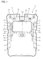
FIG. 1 is an explanatory diagram showing a ceiling member with reinforcing ribs attached thereto in one embodiment. -
FIG. 2 is an enlarged perspective view of part A ofFIG. 1 . -
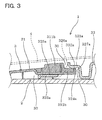
FIG. 3 is a cross-sectional view along A1-A1 ofFIG. 2 . -
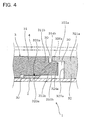
FIG. 4 is an explanatory diagram showing a simplified view of the fitted state of a first segmented rib and a second segmented rib ofFIG. 3 . -
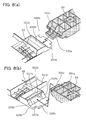
FIG. 5 is an explanatory diagram showing a state immediately before the first segmented rib and the second segmented rib are fitted with each other in the embodiment. -
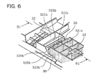
FIG. 6 is an enlarged perspective view of part B ofFIG. 1 . -
FIG. 7 is a cross-sectional view along B1-B1 ofFIG. 6 . -
FIG. 8 is an explanatory diagram showing a state immediately before the second segmented rib and a third segmented rib are fitted with each other in the embodiment. - In the present invention, the one segmented rib and the other segmented rib adjacent to each other are fitted with each other such that they are not twisted in a rotating direction around an axis extending in the longitudinal direction. Namely, the upper protrusion and lower protrusion of the one segmented rib, and the end portion of the other segmented rib, are formed such that they can fit with each other without being twisted in a rotating direction around an axis extending in the longitudinal direction.
- The upper protrusion and lower protrusion of the one segmented rib have respective tips protruding in the longitudinal direction to positions different from each other.
- The lower protrusion of the one segmented rib has its tip positioned to protrude more in the longitudinal direction than that of the upper protrusion.
The other segmented rib can be readily fitted with the one segmented rib secured to the ceiling member prior to the other. More specifically, the end portion of the other segmented rib can be readily fitted diagonally from above in between the upper protrusion and lower protrusion of the one segmented rib. - Further, the ceiling member preferably has an opening for a sunroof.
That is, the ceiling member provided with the opening for the sunroof has a lower rigidity than normal ceiling members. Therefore, attaching the reinforcing rib to the ceiling member by adopting the vehicle ceiling structure of the present invention enables to secure a sufficient rigidity of the ceiling member. - Further, the ceiling member and reinforcing rib are preferably bonded together with a hot melt adhesive.
In this case, the reinforcing rib can be readily and reliably attached to the ceiling member.
For the hot melt adhesive, polyamide, polyolefin, polyester, synthetic rubber hot melt adhesives and the like can be used. - Further, at least part of the reinforcing rib preferably serves also as an impact absorbing material.
In this case, at least part of the reinforcing rib not only serves its function as a reinforcing member for enhancing the rigidity of the ceiling member, but also serves a function as an impact absorbing material for absorbing an impact by deforming and/or breaking by an impact load applied when, for example, a head portion of a passenger inside the vehicle hits the ceiling member. - Further, at least one of the plurality of segmented ribs is preferably made of a different resin from that of other segmented ribs.
In this case, it is possible to use different types of resins depending on the attaching locations and necessary performance properties or the like of the segmented ribs to deal with various configurations. For example, a high-rigidity resin (e.g. ABS resin or the like) can be used for the segmented rib that is attached to a portion where the ceiling member is particularly desired to have enhanced rigidity, while a resin easily deformable and/or breakable for impact and having a relatively low rigidity (e.g. PP (polypropylene) resin or the like) can be used for the segmented rib that is attached to a portion where impact absorption is particularly necessary. - Using different resins for forming respective segmented ribs and bonding them using an adhesive such as a hot melt adhesive will necessitate changing adhesives respectively for the segmented ribs. However, by adopting the vehicle ceiling structure of the present invention, it is possible to use only one type of adhesive.
Namely, even if there is a segmented rib made of a resin that has somewhat lower compatibility with the adhesive used, other segmented ribs made of a resin having good compatibility with the adhesive used and arranged on both sides can provide an anchoring effect due to the fitting structure between the adjacent segmented ribs, whereby the reinforcing rib can be bonded to the ceiling member sufficiently. Thereby, a situation where two types of adhesives would have been required conventionally can be dealt with using only one type of adhesive. - For the material forming the ceiling member, a mixture or the like of a thermoplastic resin such as polypropylene, polyurethane, polyethylene terephthalate, and fiber such as wood fiber, glass fiber, can be used.
For the resin forming the reinforcing member, ABS, PP, Noryl (trademark), polycarbonate, polycarbonate ABS, PE and the like can be used. - The vehicle ceiling structure according to an embodiment of the present invention will be described with reference to
FIGS. 1 to 8 .
In this embodiment, thevehicle ceiling structure 1 is adopted in a vehicle equipped with a sunroof as shown inFIG. 1 , but the present invention is not limited to this. - As shown in the drawing, the
ceiling member 2, which is an interior material of the vehicle interior, is formed with aceiling opening 20 for the sunroof. Theceiling opening 20 is provided on the front side of theceiling member 2 and rectangular.
Long reinforcingribs 3 are respectively attached in a front to back direction on both left and right sides of the ceiling opening 20 of theceiling member 2. The reinforcingribs 3 are bonded to theceiling member 2 with a hot melt adhesive. - In this embodiment, the two reinforcing
ribs 3 attached on both left and right sides of the ceiling opening 20 of theceiling member 2 have the same configuration, except that they are provided symmetrically on the left and right. Accordingly, for convenience of explanation, one of the reinforcingribs 3 attached on the left side of the ceiling opening 20 of theceiling member 2 will be described. - As shown in
FIG. 1 , the reinforcingrib 3 is made up of a plurality of segmented ribs divided in a longitudinal direction thereof, i.e., a firstsegmented rib 31, a secondsegmented rib 32, and a thirdsegmented rib 33 in order from the front side.
As shown inFIGS. 2 and3 , the firstsegmented rib 31 and secondsegmented rib 32 fit with each other withgaps 30 therebetween in the longitudinal direction. Also, as shown inFIGS. 6 and7 , the secondsegmented rib 32 and the thirdsegmented rib 33 fit with each other withgaps 30 therebetween in the longitudinal direction. - In this embodiment, the
ceiling member 2 is formed of a mixture of thermoplastic resin and wood fiber. Further, in the reinforcingrib 3, the firstsegmented rib 31 and thirdsegmented rib 33 are attached to portions where theceiling member 2 is particularly desired to have enhanced rigidity, and therefore formed of an ABS resin having high rigidity. The secondsegmented rib 32 is attached to a portion where impact absorption is particularly necessary and therefore formed of a PP resin having a relatively low rigidity.
The firstsegmented rib 31, secondsegmented rib 32, and thirdsegmented rib 33 forming the reinforcingrib 3 are formed of materials having different coefficients of thermal expansion from that of theceiling member 2. - Next, the fitted state of the first
segmented rib 31 and secondsegmented rib 32 will be described.
As shown inFIGS. 2 to 4 , the firstsegmented rib 31 is provided, at arear end portion 311b thereof, with arear protrusion 312b protruding in a backward direction. The secondsegmented rib 32 is provided, on an upper side of afront end portion 321a thereof, with anupper front protrusion 322a protruding in a forward direction, and on a lower side thereof, with alower front protrusion 323a protruding in the forward direction. Thelower front protrusion 323a has its tip positioned to protrude more in the longitudinal direction than that of theupper front protrusion 322a. - As shown in the same drawings, the
upper front protrusion 322a and lowerfront protrusion 323a are coupled to each other byfront coupling portions 326a provided on both sides of thefront end portion 321a of the secondsegmented rib 32. Between theupper front protrusion 322a and lowerfront protrusion 323a is formed a frontfitting portion 327a for allowing therear protrusion 312b of the firstsegmented rib 31 to fit therewith. - As shown in the same drawings, the first
segmented rib 31 and secondsegmented rib 32 are secured together by making therear protrusion 312b of the firstsegmented rib 31 fit with the frontfitting portion 327a of the secondsegmented rib 32. Alower face 324a of theupper front protrusion 322a of the secondsegmented rib 32 faces anupper face 314b of therear protrusion 312b of the firstsegmented rib 31 in the up and down direction. Anupper face 325a of thelower front protrusion 323a of the secondsegmented rib 32 faces alower face 315b of therear protrusion 312b of the firstsegmented rib 31 in the up and down direction. - Namely, as shown in the same drawings, the first
segmented rib 31 is fitted in such a state that therear protrusion 312b thereof is restricted in the up and down direction by thelower face 324a of theupper front protrusion 322a and theupper face 325a of thelower front protrusion 323a of the secondsegmented rib 32. Further, the firstsegmented rib 31 is fitted in such a state that therear protrusion 312b thereof is restricted in the left and right direction by thefront coupling portions 326a of the secondsegmented rib 32.
FIG. 2 is an enlarged perspective view of part A ofFIG. 1 .FIG. 3 is a cross-sectional view along A1-A1 ofFIG. 2 .FIG. 4 is a diagram showing a simplified view ofFIG. 3 . - Next, the fitted state of the second
segmented rib 32 and thirdsegmented rib 33 will be described.
As shown inFIGS. 6 and7 , the thirdsegmented rib 33 is provided, at afront end portion 331a thereof, with afront protrusion 332a protruding in the forward direction. The secondsegmented rib 32 is provided, on an upper side of arear end portion 321b thereof, with an upperrear protrusion 322b protruding in the backward direction, and on a lower side thereof, with a lowerrear protrusion 323b protruding in the backward direction. The lowerrear protrusion 323b has its tip positioned to protrude more in the longitudinal direction than that of the upperrear protrusion 322b. - As shown in the same drawings, the upper
rear protrusion 322b and lowerrear protrusion 323b are coupled to each other byrear coupling portions 326b provided on both sides of therear end portion 321b of the secondsegmented rib 32. Between the upperrear protrusion 322b and lowerrear protrusion 323b is formed a rearfitting portion 327b for allowing thefront protrusion 332a of the thirdsegmented rib 33 to fit therewith. - As shown in the same drawings, the second
segmented rib 32 and thirdsegmented rib 33 are secured together by making thefront protrusion 332a of the thirdsegmented rib 33 fit with the rearfitting portion 327b of the secondsegmented rib 32. Alower face 324b of the upperrear protrusion 322b of the secondsegmented rib 32 faces anupper face 334a of thefront protrusion 332a of the thirdsegmented rib 33 in the up and down direction. Anupper face 325b of the lowerrear protrusion 323b of the secondsegmented rib 32 faces alower face 335a of thefront protrusion 332a of the thirdsegmented rib 33 in the up and down direction. - Namely, as shown in the same drawings, the third
segmented rib 33 is fitted in such a state that thefront protrusion 332a thereof is restricted in the up and down direction by thelower face 324b of the upperrear protrusion 322b and theupper face 325b of the lowerrear protrusion 323b of the secondsegmented rib 32. Further, the thirdsegmented rib 33 is fitted in such a state that thefront protrusion 332a thereof is restricted in the left and right direction by therear coupling portions 326b of the secondsegmented rib 32.
FIG. 6 is an enlarged perspective view of part B ofFIG. 1 .FIG. 7 is a cross-sectional view along B1-B1 ofFIG. 6 . - Next, steps of attaching the reinforcing
rib 3 to theceiling member 2 will be described.
First, as shown inFIGS. 5(a) and 5(b) , therear protrusion 312b of the firstsegmented rib 31 is inserted and fitted backward into the frontfitting portion 327a of the secondsegmented rib 32 so as to assemble the firstsegmented rib 31 with the secondsegmented rib 32. - Then, as shown in
FIGS. 8(a) and 8(b) , thefront protrusion 332a of the thirdsegmented rib 33 is inserted and fitted forward into the rearfitting portion 327b of the secondsegmented rib 32 so as to assemble the secondsegmented rib 32 with the thirdsegmented rib 33.
Thus the firstsegmented rib 31, secondsegmented rib 32, and thirdsegmented rib 33 are assembled together to obtain the reinforcingrib 3. - Next, hot melt adhesive in a molten state is applied to a location on the
ceiling member 2 where the reinforcingrib 3 is to be attached. For the hot melt adhesive in this embodiment, a polyamide hot melt adhesive was used.
After setting the reinforcingrib 3 on the hot melt adhesive, the hot melt adhesive is cooled and cured to bond the reinforcingrib 3.
The reinforcingrib 3 is thus attached to theceiling member 2. - Further, after that, the
ceiling member 2, with the reinforcingrib 3 attached thereto, is secured to a body member 4 (seeFIGS. 3 ,4 and7 ) forming the vehicle body, together with assist grips, a room lamp, sun visors and the like respectively provided at assistgrip fixing portions 71, a roomlamp fixing portion 72, and sunvisor fixing portions 73 and the like (seeFIG. 1 ). - Next, the effects achieved by the
vehicle ceiling structure 1 of this embodiment will be described.
In thevehicle ceiling structure 1 of this embodiment, the reinforcingrib 3 is not formed in one piece but comprises a plurality ofsegmented ribs 31 to 33 divided bygaps 30 in the longitudinal direction. Therefore, after the reinforcingrib 3 is attached to theceiling member 2 and when they undergo thermal expansion and contraction due to temperature changes thereof, the difference in the amount of expansion and contraction caused by the difference in their respective coefficients of thermal expansion can be made smaller. Namely, since thermal expansion and contraction occur respectively in each of the plurality ofsegmented ribs 31 to 33 that are divided of the reinforcingrib 3, the difference in the amount of expansion and contraction between the reinforcingrib 3 and theceiling member 2 can be made smaller. Thereby, formation of wrinkles in theceiling member 2 after the attachment of the reinforcingrib 3 can be prevented. - Moreover, in this embodiment, as shown in
FIG. 4 , and as will be explained taking the firstsegmented rib 31 and secondsegmented rib 32 adjacent to each other as one example and using the simplified view (simplified view ofFIG. 3 ) of how they fit with each other, the firstsegmented rib 31 and secondsegmented rib 32 fit with each other such that thelower face 324a of theupper front protrusion 322a and theupper face 325a of thelower front protrusion 323a of the secondsegmented rib 32 respectively face therear end portion 312b of the firstsegmented rib 31 in the up and down direction. Namely, the secondsegmented rib 32 has thelower face 324a of theupper front protrusion 322a and theupper face 325a of thelower front protrusion 323a in upper and lower parts of itsfront end portion 321a to act as abutting faces relative to the firstsegmented rib 31, so that therear end portion 312b of the firstsegmented rib 31 faces these abutting faces in the up and down direction. - Accordingly, the first
segmented rib 31 and secondsegmented rib 32 fit with each other in a state in which the firstsegmented rib 31 is restricted relative to the secondsegmented rib 32 sufficiently in the up and down direction. Thereby, during the handling when assembling theceiling member 2 to the vehicle body after attaching the reinforcingrib 3 to theceiling member 2, even if the firstsegmented rib 31 and secondsegmented rib 32 are subjected to stress in the portion between them (segmented portion), flexing or bending of theceiling member 2 can be prevented from occurring. The same applies to the portion between the secondsegmented rib 32 and thirdsegmented rib 33. - Accordingly, in the
vehicle ceiling structure 1 of this embodiment, the problems associated with the difference in the coefficient of thermal expansion between theceiling member 2 and reinforcingrib 3 can be prevented by forming the reinforcingrib 3 with a plurality ofsegmented ribs 31 to 33. And, the problem that may occur by forming the reinforcingrib 3 with a plurality ofsegmented ribs 31 to 33 can be prevented by the fitting structure between adjacentsegmented ribs 31 to 33. - In this embodiment, the first
segmented rib 31 and secondsegmented rib 32 adjacent to each other are fitted with each other such that they are not twisted in a rotating direction around an axis extending in the longitudinal direction. Namely, the firstsegmented rib 31 is fitted in such a state that itsrear protrusion 312b is restricted relative to the secondsegmented rib 32 in the up and down direction as well as in the left and right direction. Thus the firstsegmented rib 31 and secondsegmented rib 32 adjacent to each other can be sufficiently and reliably fitted with each other. - Similarly, the second
segmented rib 32 and thirdsegmented rib 33 adjacent to each other are fitted with each other such that they are not twisted in a rotating direction around an axis extending in the longitudinal direction. Namely, the thirdsegmented rib 33 is fitted in such a state that itsfront protrusion 332a is restricted relative to the secondsegmented rib 32 in the up and down direction as well as in the left and right direction. Thus the secondsegmented rib 32 and thirdsegmented rib 33 adjacent to each other can be sufficiently and reliably fitted with each other. - Further, the
lower front protrusion 323a of the secondsegmented rib 32 has its tip positioned to protrude more in the longitudinal direction than that of theupper front protrusion 322a. Therefore, as shown inFIGS. 5(a) and 5(b) , therear protrusion 312b of the firstsegmented rib 31 can be readily inserted and fitted diagonally from above into the frontfitting portion 327a of the secondsegmented rib 32. - Also, the lower
rear protrusion 323b of the secondsegmented rib 32 has its tip positioned to protrude more in the longitudinal direction than that of the upperrear protrusion 322b. Therefore, as shown inFIGS. 8(a) and 8(b) , thefront protrusion 332a of the thirdsegmented rib 33 can be readily inserted and fitted diagonally from above into the rearfitting portion 327b of the secondsegmented rib 32. - Further, the
ceiling member 2 has anopening 20 for the sunroof. That is, theceiling member 2 provided with theopening 20 for the sunroof has a lower rigidity thannormal ceiling members 2. Therefore, attaching the reinforcingrib 3 to theceiling member 2 by adopting thevehicle ceiling structure 1 of this embodiment enables to secure a sufficient rigidity of theceiling member 2.
Theceiling member 2 and reinforcingrib 3 are bonded together with a hot melt adhesive. Therefore, the reinforcingrib 3 can be readily and reliably attached to theceiling member 2. - Further, part of the reinforcing
rib 3 serves also as an impact absorbing material. In this embodiment, the secondsegmented rib 32 corresponds to this part. Therefore, the secondsegmented rib 32 not only serves its function as a reinforcing member for enhancing the rigidity of theceiling member 2, but also serves a function as an impact absorbing material for absorbing an impact by deforming and/or breaking by an impact load applied when, for example, a head portion of a passenger inside the vehicle hits theceiling member 2. - Further, in the reinforcing
rib 3, the secondsegmented rib 32 is made of a different resin from that of the firstsegmented rib 31 and thirdsegmented rib 33. Namely, dividing up the reinforcingrib 3 into a plurality ofsegmented ribs 31 to 33 has made it possible to use different types of resins depending on the attaching locations and necessary performance properties or the like of thesegmented ribs 31 to 33 to deal with various configurations.
In this embodiment, a high-rigidity resin (ABS resin) is used for the firstsegmented rib 31 and thirdsegmented rib 33 that are attached to portions where theceiling member 2 is particularly desired to have enhanced rigidity, while a resin easily deformable and/or breakable and having a relatively low rigidity (PP resin) is used for the secondsegmented rib 32 that is attached to a portion where impact absorption is particularly necessary. - Using different resins for forming respective
segmented ribs 31 to 33 and bonding them using a hot melt adhesive as in this embodiment will necessitate a change of adhesives respectively for thesegmented ribs 31 to 33. However, by adopting thevehicle ceiling structure 1 of this embodiment, it is possible to use only one type of adhesive.
Namely, even if there is a segmented rib (for example, second segmented rib 32) made of a resin that has somewhat lower compatibility with the hot melt adhesive used, other segmented ribs (for example, firstsegmented rib 31 and third segmented rib 33) made of a resin having good compatibility with the adhesive used and arranged on both sides can provide an anchoring effect due to the fitting structure between adjacentsegmented ribs 31 to 33, whereby the reinforcingrib 3 can be bonded to theceiling member 2 sufficiently. Thereby, a situation where two types of adhesives would have been required conventionally can be dealt with using only one type of adhesive. - As described above, according to this embodiment, a
vehicle ceiling structure 1 that can prevent occurrence of failures such as wrinkles, flexing, bending or the like of theceiling member 2 can be provided.
Claims (5)
- A vehicle ceiling structure (1) having a long reinforcing rib (13) attached to a ceiling member (2) of the vehicle, the rib (13) being made of a resin having a different coefficient of thermal expansion from that of the ceiling member (2), wherein
the reinforcing rib (3) comprises a plurality of segmented ribs (31, 32, 33) that are divided by a gap (30) in a longitudinal direction;
one of the segmented ribs (32) adjacent to each other is formed, in upper and lower parts of an end portion thereof, with an upper protrusion (332a, 322b) and a lower protrusion (323a, 323b) protruding in the longitudinal direction;
the one segmented rib (32) and the other segmented rib (31, 33) fit with each other such that a lower face (324a, 324b) of the upper protrusion (322a, 322b) and an upper face of the lower protrusion of the one segmented rib (32) respectively face an end portion (311b, 331a) of the other segmented rib (31, 33) in an up and down direction; characterized in that
the lower protrusion (323a, 323b) of the one segmented rib (32) has its tip positioned to protrude more in the longitudinal direction than that of the upper protrusion (322a, 322b), - The vehicle ceiling structure (1) according to claim 1, wherein the ceiling member has an opening for sunroof (20).
- The vehicle ceiling structure (1) according to claim 1 or 2, wherein the ceiling member (2) and the reinforcing rib (3) are bonded together with a hot melt adhesives.
- The vehicle ceiling structure (1) according to any one of claims 1 to 3, wherein at least part of the reinforcing rib (3) serves also as an impact absorbing material.
- The vehicle ceiling structure (1) according to any one of claims 1 to 4, wherein at least one of the plurality of segmented ribs is made of a different resin from that of the other segmented ribs (31, 32, 33).
Applications Claiming Priority (2)
| Application Number | Priority Date | Filing Date | Title |
|---|---|---|---|
| JP2008187990A JP5137248B2 (en) | 2008-07-21 | 2008-07-21 | Vehicle ceiling structure |
| PCT/JP2009/055237 WO2010010734A1 (en) | 2008-07-21 | 2009-03-18 | Vehicle ceiling structure |
Publications (3)
| Publication Number | Publication Date |
|---|---|
| EP2305517A1 EP2305517A1 (en) | 2011-04-06 |
| EP2305517A4 EP2305517A4 (en) | 2012-01-04 |
| EP2305517B1 true EP2305517B1 (en) | 2012-12-05 |
Family
ID=41570202
Family Applications (1)
| Application Number | Title | Priority Date | Filing Date |
|---|---|---|---|
| EP09800250A Not-in-force EP2305517B1 (en) | 2008-07-21 | 2009-03-18 | Vehicle ceiling structure |
Country Status (7)
| Country | Link |
|---|---|
| US (1) | US8091953B2 (en) |
| EP (1) | EP2305517B1 (en) |
| JP (1) | JP5137248B2 (en) |
| CN (1) | CN102099224B (en) |
| AU (1) | AU2009275077B2 (en) |
| CA (1) | CA2731540C (en) |
| WO (1) | WO2010010734A1 (en) |
Families Citing this family (7)
| Publication number | Priority date | Publication date | Assignee | Title |
|---|---|---|---|---|
| JP5818097B2 (en) * | 2012-03-30 | 2015-11-18 | トヨタ紡織株式会社 | Vehicle ceiling structure |
| EP3272590B1 (en) | 2015-03-18 | 2018-12-19 | Grupo Antonlín-Ingeniería, S.A. | Headliner for vehicle roof with transparent portion |
| CN106143386B (en) * | 2015-03-30 | 2020-02-04 | 天津博信汽车零部件有限公司 | Roof energy-absorbing structure in car, car roof and vehicle |
| DE102018205683B4 (en) * | 2018-04-13 | 2024-02-29 | Bayerische Motoren Werke Aktiengesellschaft | ROOF SYSTEM FOR A VEHICLE, VEHICLE HAVING SUCH A ROOF SYSTEM, ROOF ELEMENT AND PRODUCTION METHOD |
| JP7331668B2 (en) | 2018-12-03 | 2023-08-23 | トヨタ紡織株式会社 | Adhesion method |
| JP2020094204A (en) * | 2018-12-03 | 2020-06-18 | トヨタ紡織株式会社 | Two agent type hot melt adhesive, solidified product and method for controlling crosslinking time |
| US11648891B2 (en) * | 2019-11-04 | 2023-05-16 | Nyx, Inc. | Low-pressure molded vehicle headliner with bridge |
Family Cites Families (18)
| Publication number | Priority date | Publication date | Assignee | Title |
|---|---|---|---|---|
| JPS5861039A (en) * | 1981-10-05 | 1983-04-11 | Nissan Motor Co Ltd | Garnish interface constitution for vehicle |
| DE19632055C1 (en) * | 1996-08-09 | 1997-11-13 | Benecke Kaliko Ag | Moulding method for vehicle roof lining reinforcement |
| US6267436B1 (en) * | 1998-07-22 | 2001-07-31 | Toyota Jidosha Kabushiki Kaisha | Impact energy absorbing structure in upper vehicle body portion, and impact energy absorbing component |
| US6250711B1 (en) * | 1998-07-31 | 2001-06-26 | Toyota Jidosha Kabushiki Kaisha | Energy absorber securing structure and method |
| US6264238B1 (en) * | 1999-09-28 | 2001-07-24 | Daimlerchrysler Corporation | Reactive surface rib cartridge countermeasure for vehicle interior hard trim applications |
| US6475937B1 (en) * | 2000-03-17 | 2002-11-05 | Patent Holding Company | Lightweight, thermoplastic, vehicle headliner having at least one integrally-formed, energy-absorbing, head-impact mechanism and injection molding method for making same |
| US6588557B2 (en) * | 2001-04-04 | 2003-07-08 | Daimlerchrysler Corporation | Blow molded (HIC) formation with energy buffers |
| CA2454911A1 (en) * | 2001-07-24 | 2003-02-06 | Dario Soto Romero | Procedure for obtaining roof lining with intergrated lighting system and lining so obtained |
| US6779835B2 (en) * | 2001-12-06 | 2004-08-24 | Lear Corporation | Energy absorbing structure for automobile interior |
| US6679544B1 (en) * | 2002-04-05 | 2004-01-20 | Lear Corporation | Molded energy absorber |
| JP2003320915A (en) | 2002-05-07 | 2003-11-11 | Fuji Heavy Ind Ltd | Impact absorption rib structure in cabin |
| US6652021B1 (en) * | 2002-11-06 | 2003-11-25 | Lear Corporation | Integrated headliner assembly |
| US20050168015A1 (en) * | 2004-01-29 | 2005-08-04 | Intier Automotive Inc. | Headliner with integrally-molded energy distribution zone |
| JP4514528B2 (en) | 2004-06-18 | 2010-07-28 | 株式会社イノアックコーポレーション | Shock absorbing member |
| JP4609282B2 (en) * | 2004-12-28 | 2011-01-12 | トヨタ車体株式会社 | Vehicle ceiling material |
| JP4548207B2 (en) * | 2005-04-28 | 2010-09-22 | スズキ株式会社 | Cushioning member mounting structure in vehicle roof |
| JP2007145234A (en) | 2005-11-29 | 2007-06-14 | Kasai Kogyo Co Ltd | Shock absorbing body for vehicle |
| US7841647B2 (en) * | 2006-11-15 | 2010-11-30 | Sika Technology Ag | Baffle assembly |
-
2008
- 2008-07-21 JP JP2008187990A patent/JP5137248B2/en active Active
-
2009
- 2009-03-18 US US13/055,365 patent/US8091953B2/en not_active Expired - Fee Related
- 2009-03-18 CN CN200980128509.1A patent/CN102099224B/en not_active Expired - Fee Related
- 2009-03-18 CA CA2731540A patent/CA2731540C/en not_active Expired - Fee Related
- 2009-03-18 WO PCT/JP2009/055237 patent/WO2010010734A1/en active Application Filing
- 2009-03-18 EP EP09800250A patent/EP2305517B1/en not_active Not-in-force
- 2009-03-18 AU AU2009275077A patent/AU2009275077B2/en not_active Ceased
Also Published As
| Publication number | Publication date |
|---|---|
| EP2305517A1 (en) | 2011-04-06 |
| EP2305517A4 (en) | 2012-01-04 |
| US20110187158A1 (en) | 2011-08-04 |
| AU2009275077A1 (en) | 2010-01-28 |
| WO2010010734A1 (en) | 2010-01-28 |
| CA2731540A1 (en) | 2010-01-28 |
| AU2009275077B2 (en) | 2011-11-03 |
| CN102099224A (en) | 2011-06-15 |
| CA2731540C (en) | 2013-05-28 |
| JP2010023694A (en) | 2010-02-04 |
| CN102099224B (en) | 2012-12-26 |
| JP5137248B2 (en) | 2013-02-06 |
| US8091953B2 (en) | 2012-01-10 |
Similar Documents
| Publication | Publication Date | Title |
|---|---|---|
| EP2305517B1 (en) | Vehicle ceiling structure | |
| EP2796326B1 (en) | Automobile fiber-strengthening resin member and method for producing automobile fiber-strengthening resin member | |
| KR101760523B1 (en) | Transverse-member module for a motor vehicle | |
| US11198477B2 (en) | Opening panel made from plastic, which continues to block the opening in the body shell in the event of an impact | |
| KR20160015331A (en) | Method for producing a structural component for motor vehicles from an organo-sheet | |
| CN107757723B (en) | Reinforced textile wheel arch cover lining | |
| US11273872B2 (en) | Vehicle structural component and method for producing a vehicle structural component | |
| KR101945560B1 (en) | front end module carrier using continuous fiber reinforced thermoplastics and method of manufacturing | |
| CN109080555A (en) | Tape reinforced plastics cladding parts and its manufacturing method | |
| CN111226058A (en) | Bracket for vibration isolator and method for manufacturing bracket for vibration isolator | |
| KR101264173B1 (en) | Impact absorbing structure of door trim for a car with improved maintenance | |
| JP3942597B2 (en) | Molded product assembly and manufacturing method thereof | |
| US11465473B2 (en) | Interfacing element for a lock zone of a motor vehicle door | |
| KR102291228B1 (en) | Lightweight integral window channel assembly | |
| KR102009793B1 (en) | Seat back frame and method of manufacturing the same | |
| KR100826680B1 (en) | Trim molding for motors and the manufacturing method thereof | |
| KR102022550B1 (en) | Lightweight tailgate assembly | |
| US20070087200A1 (en) | Composite vehicle panel | |
| US20240075988A1 (en) | Vehicle Roof Assembly and Method for Manufacturing the Same | |
| JP7060883B2 (en) | How to apply the skin material | |
| JP7156757B2 (en) | Vehicle pillar structure | |
| CN113195201B (en) | Vehicle body element comprising an appearance part glued to a structural part | |
| JPH0924781A (en) | Armature molding structure for bumper made of resin | |
| JP2003145628A (en) | Connecting structure of panels made of frp with each other | |
| JPS61238576A (en) | Outer panel of automobile |
Legal Events
| Date | Code | Title | Description |
|---|---|---|---|
| PUAI | Public reference made under article 153(3) epc to a published international application that has entered the european phase |
Free format text: ORIGINAL CODE: 0009012 |
|
| 17P | Request for examination filed |
Effective date: 20110120 |
|
| AK | Designated contracting states |
Kind code of ref document: A1 Designated state(s): AT BE BG CH CY CZ DE DK EE ES FI FR GB GR HR HU IE IS IT LI LT LU LV MC MK MT NL NO PL PT RO SE SI SK TR |
|
| AX | Request for extension of the european patent |
Extension state: AL BA RS |
|
| DAX | Request for extension of the european patent (deleted) | ||
| A4 | Supplementary search report drawn up and despatched |
Effective date: 20111202 |
|
| RIC1 | Information provided on ipc code assigned before grant |
Ipc: B60R 21/04 20060101ALI20111128BHEP Ipc: B60R 13/02 20060101AFI20111128BHEP |
|
| GRAP | Despatch of communication of intention to grant a patent |
Free format text: ORIGINAL CODE: EPIDOSNIGR1 |
|
| RIC1 | Information provided on ipc code assigned before grant |
Ipc: B60R 13/02 20060101AFI20120608BHEP Ipc: B60R 21/04 20060101ALI20120608BHEP |
|
| GRAS | Grant fee paid |
Free format text: ORIGINAL CODE: EPIDOSNIGR3 |
|
| GRAA | (expected) grant |
Free format text: ORIGINAL CODE: 0009210 |
|
| AK | Designated contracting states |
Kind code of ref document: B1 Designated state(s): AT BE BG CH CY CZ DE DK EE ES FI FR GB GR HR HU IE IS IT LI LT LU LV MC MK MT NL NO PL PT RO SE SI SK TR |
|
| REG | Reference to a national code |
Ref country code: GB Ref legal event code: FG4D |
|
| REG | Reference to a national code |
Ref country code: CH Ref legal event code: EP |
|
| REG | Reference to a national code |
Ref country code: AT Ref legal event code: REF Ref document number: 587082 Country of ref document: AT Kind code of ref document: T Effective date: 20121215 |
|
| REG | Reference to a national code |
Ref country code: IE Ref legal event code: FG4D |
|
| REG | Reference to a national code |
Ref country code: DE Ref legal event code: R096 Ref document number: 602009011814 Country of ref document: DE Effective date: 20130131 |
|
| REG | Reference to a national code |
Ref country code: AT Ref legal event code: MK05 Ref document number: 587082 Country of ref document: AT Kind code of ref document: T Effective date: 20121205 |
|
| PG25 | Lapsed in a contracting state [announced via postgrant information from national office to epo] |
Ref country code: ES Free format text: LAPSE BECAUSE OF FAILURE TO SUBMIT A TRANSLATION OF THE DESCRIPTION OR TO PAY THE FEE WITHIN THE PRESCRIBED TIME-LIMIT Effective date: 20130316 Ref country code: FI Free format text: LAPSE BECAUSE OF FAILURE TO SUBMIT A TRANSLATION OF THE DESCRIPTION OR TO PAY THE FEE WITHIN THE PRESCRIBED TIME-LIMIT Effective date: 20121205 Ref country code: LT Free format text: LAPSE BECAUSE OF FAILURE TO SUBMIT A TRANSLATION OF THE DESCRIPTION OR TO PAY THE FEE WITHIN THE PRESCRIBED TIME-LIMIT Effective date: 20121205 Ref country code: SE Free format text: LAPSE BECAUSE OF FAILURE TO SUBMIT A TRANSLATION OF THE DESCRIPTION OR TO PAY THE FEE WITHIN THE PRESCRIBED TIME-LIMIT Effective date: 20121205 Ref country code: NO Free format text: LAPSE BECAUSE OF FAILURE TO SUBMIT A TRANSLATION OF THE DESCRIPTION OR TO PAY THE FEE WITHIN THE PRESCRIBED TIME-LIMIT Effective date: 20130305 |
|
| REG | Reference to a national code |
Ref country code: NL Ref legal event code: VDEP Effective date: 20121205 |
|
| REG | Reference to a national code |
Ref country code: LT Ref legal event code: MG4D |
|
| PG25 | Lapsed in a contracting state [announced via postgrant information from national office to epo] |
Ref country code: SI Free format text: LAPSE BECAUSE OF FAILURE TO SUBMIT A TRANSLATION OF THE DESCRIPTION OR TO PAY THE FEE WITHIN THE PRESCRIBED TIME-LIMIT Effective date: 20121205 Ref country code: LV Free format text: LAPSE BECAUSE OF FAILURE TO SUBMIT A TRANSLATION OF THE DESCRIPTION OR TO PAY THE FEE WITHIN THE PRESCRIBED TIME-LIMIT Effective date: 20121205 Ref country code: PL Free format text: LAPSE BECAUSE OF FAILURE TO SUBMIT A TRANSLATION OF THE DESCRIPTION OR TO PAY THE FEE WITHIN THE PRESCRIBED TIME-LIMIT Effective date: 20121205 Ref country code: GR Free format text: LAPSE BECAUSE OF FAILURE TO SUBMIT A TRANSLATION OF THE DESCRIPTION OR TO PAY THE FEE WITHIN THE PRESCRIBED TIME-LIMIT Effective date: 20130306 |
|
| PG25 | Lapsed in a contracting state [announced via postgrant information from national office to epo] |
Ref country code: AT Free format text: LAPSE BECAUSE OF FAILURE TO SUBMIT A TRANSLATION OF THE DESCRIPTION OR TO PAY THE FEE WITHIN THE PRESCRIBED TIME-LIMIT Effective date: 20121205 |
|
| PG25 | Lapsed in a contracting state [announced via postgrant information from national office to epo] |
Ref country code: CZ Free format text: LAPSE BECAUSE OF FAILURE TO SUBMIT A TRANSLATION OF THE DESCRIPTION OR TO PAY THE FEE WITHIN THE PRESCRIBED TIME-LIMIT Effective date: 20121205 Ref country code: BG Free format text: LAPSE BECAUSE OF FAILURE TO SUBMIT A TRANSLATION OF THE DESCRIPTION OR TO PAY THE FEE WITHIN THE PRESCRIBED TIME-LIMIT Effective date: 20130305 Ref country code: EE Free format text: LAPSE BECAUSE OF FAILURE TO SUBMIT A TRANSLATION OF THE DESCRIPTION OR TO PAY THE FEE WITHIN THE PRESCRIBED TIME-LIMIT Effective date: 20121205 Ref country code: SK Free format text: LAPSE BECAUSE OF FAILURE TO SUBMIT A TRANSLATION OF THE DESCRIPTION OR TO PAY THE FEE WITHIN THE PRESCRIBED TIME-LIMIT Effective date: 20121205 Ref country code: BE Free format text: LAPSE BECAUSE OF FAILURE TO SUBMIT A TRANSLATION OF THE DESCRIPTION OR TO PAY THE FEE WITHIN THE PRESCRIBED TIME-LIMIT Effective date: 20121205 Ref country code: IS Free format text: LAPSE BECAUSE OF FAILURE TO SUBMIT A TRANSLATION OF THE DESCRIPTION OR TO PAY THE FEE WITHIN THE PRESCRIBED TIME-LIMIT Effective date: 20130405 |
|
| PG25 | Lapsed in a contracting state [announced via postgrant information from national office to epo] |
Ref country code: RO Free format text: LAPSE BECAUSE OF FAILURE TO SUBMIT A TRANSLATION OF THE DESCRIPTION OR TO PAY THE FEE WITHIN THE PRESCRIBED TIME-LIMIT Effective date: 20121205 Ref country code: NL Free format text: LAPSE BECAUSE OF FAILURE TO SUBMIT A TRANSLATION OF THE DESCRIPTION OR TO PAY THE FEE WITHIN THE PRESCRIBED TIME-LIMIT Effective date: 20121205 Ref country code: PT Free format text: LAPSE BECAUSE OF FAILURE TO SUBMIT A TRANSLATION OF THE DESCRIPTION OR TO PAY THE FEE WITHIN THE PRESCRIBED TIME-LIMIT Effective date: 20130405 |
|
| PLBE | No opposition filed within time limit |
Free format text: ORIGINAL CODE: 0009261 |
|
| STAA | Information on the status of an ep patent application or granted ep patent |
Free format text: STATUS: NO OPPOSITION FILED WITHIN TIME LIMIT |
|
| PG25 | Lapsed in a contracting state [announced via postgrant information from national office to epo] |
Ref country code: MC Free format text: LAPSE BECAUSE OF NON-PAYMENT OF DUE FEES Effective date: 20130331 Ref country code: DK Free format text: LAPSE BECAUSE OF FAILURE TO SUBMIT A TRANSLATION OF THE DESCRIPTION OR TO PAY THE FEE WITHIN THE PRESCRIBED TIME-LIMIT Effective date: 20121205 |
|
| REG | Reference to a national code |
Ref country code: CH Ref legal event code: PL |
|
| 26N | No opposition filed |
Effective date: 20130906 |
|
| PG25 | Lapsed in a contracting state [announced via postgrant information from national office to epo] |
Ref country code: CY Free format text: LAPSE BECAUSE OF FAILURE TO SUBMIT A TRANSLATION OF THE DESCRIPTION OR TO PAY THE FEE WITHIN THE PRESCRIBED TIME-LIMIT Effective date: 20121205 |
|
| PG25 | Lapsed in a contracting state [announced via postgrant information from national office to epo] |
Ref country code: IT Free format text: LAPSE BECAUSE OF FAILURE TO SUBMIT A TRANSLATION OF THE DESCRIPTION OR TO PAY THE FEE WITHIN THE PRESCRIBED TIME-LIMIT Effective date: 20121205 |
|
| REG | Reference to a national code |
Ref country code: IE Ref legal event code: MM4A |
|
| REG | Reference to a national code |
Ref country code: DE Ref legal event code: R097 Ref document number: 602009011814 Country of ref document: DE Effective date: 20130906 |
|
| PG25 | Lapsed in a contracting state [announced via postgrant information from national office to epo] |
Ref country code: LI Free format text: LAPSE BECAUSE OF NON-PAYMENT OF DUE FEES Effective date: 20130331 Ref country code: IE Free format text: LAPSE BECAUSE OF NON-PAYMENT OF DUE FEES Effective date: 20130318 Ref country code: CH Free format text: LAPSE BECAUSE OF NON-PAYMENT OF DUE FEES Effective date: 20130331 Ref country code: HR Free format text: LAPSE BECAUSE OF FAILURE TO SUBMIT A TRANSLATION OF THE DESCRIPTION OR TO PAY THE FEE WITHIN THE PRESCRIBED TIME-LIMIT Effective date: 20130731 |
|
| PG25 | Lapsed in a contracting state [announced via postgrant information from national office to epo] |
Ref country code: MT Free format text: LAPSE BECAUSE OF FAILURE TO SUBMIT A TRANSLATION OF THE DESCRIPTION OR TO PAY THE FEE WITHIN THE PRESCRIBED TIME-LIMIT Effective date: 20121205 |
|
| PG25 | Lapsed in a contracting state [announced via postgrant information from national office to epo] |
Ref country code: TR Free format text: LAPSE BECAUSE OF FAILURE TO SUBMIT A TRANSLATION OF THE DESCRIPTION OR TO PAY THE FEE WITHIN THE PRESCRIBED TIME-LIMIT Effective date: 20121205 |
|
| PG25 | Lapsed in a contracting state [announced via postgrant information from national office to epo] |
Ref country code: MK Free format text: LAPSE BECAUSE OF FAILURE TO SUBMIT A TRANSLATION OF THE DESCRIPTION OR TO PAY THE FEE WITHIN THE PRESCRIBED TIME-LIMIT Effective date: 20121205 Ref country code: LU Free format text: LAPSE BECAUSE OF NON-PAYMENT OF DUE FEES Effective date: 20130318 Ref country code: HU Free format text: LAPSE BECAUSE OF FAILURE TO SUBMIT A TRANSLATION OF THE DESCRIPTION OR TO PAY THE FEE WITHIN THE PRESCRIBED TIME-LIMIT; INVALID AB INITIO Effective date: 20090318 |
|
| REG | Reference to a national code |
Ref country code: FR Ref legal event code: PLFP Year of fee payment: 8 |
|
| REG | Reference to a national code |
Ref country code: FR Ref legal event code: PLFP Year of fee payment: 9 |
|
| REG | Reference to a national code |
Ref country code: FR Ref legal event code: PLFP Year of fee payment: 10 |
|
| PGFP | Annual fee paid to national office [announced via postgrant information from national office to epo] |
Ref country code: DE Payment date: 20190305 Year of fee payment: 11 Ref country code: GB Payment date: 20190313 Year of fee payment: 11 |
|
| PGFP | Annual fee paid to national office [announced via postgrant information from national office to epo] |
Ref country code: FR Payment date: 20190213 Year of fee payment: 11 |
|
| REG | Reference to a national code |
Ref country code: DE Ref legal event code: R119 Ref document number: 602009011814 Country of ref document: DE |
|
| PG25 | Lapsed in a contracting state [announced via postgrant information from national office to epo] |
Ref country code: DE Free format text: LAPSE BECAUSE OF NON-PAYMENT OF DUE FEES Effective date: 20201001 Ref country code: FR Free format text: LAPSE BECAUSE OF NON-PAYMENT OF DUE FEES Effective date: 20200331 |
|
| GBPC | Gb: european patent ceased through non-payment of renewal fee |
Effective date: 20200318 |
|
| PG25 | Lapsed in a contracting state [announced via postgrant information from national office to epo] |
Ref country code: GB Free format text: LAPSE BECAUSE OF NON-PAYMENT OF DUE FEES Effective date: 20200318 |