EP2305482A1 - Device for preventing caught-in of label without mount in thermal printer - Google Patents
Device for preventing caught-in of label without mount in thermal printer Download PDFInfo
- Publication number
- EP2305482A1 EP2305482A1 EP09840184A EP09840184A EP2305482A1 EP 2305482 A1 EP2305482 A1 EP 2305482A1 EP 09840184 A EP09840184 A EP 09840184A EP 09840184 A EP09840184 A EP 09840184A EP 2305482 A1 EP2305482 A1 EP 2305482A1
- Authority
- EP
- European Patent Office
- Prior art keywords
- roll
- platen roller
- preventing
- linerless label
- label
- Prior art date
- Legal status (The legal status is an assumption and is not a legal conclusion. Google has not performed a legal analysis and makes no representation as to the accuracy of the status listed.)
- Granted
Links
Images


Classifications
-
- B—PERFORMING OPERATIONS; TRANSPORTING
- B41—PRINTING; LINING MACHINES; TYPEWRITERS; STAMPS
- B41J—TYPEWRITERS; SELECTIVE PRINTING MECHANISMS, i.e. MECHANISMS PRINTING OTHERWISE THAN FROM A FORME; CORRECTION OF TYPOGRAPHICAL ERRORS
- B41J3/00—Typewriters or selective printing or marking mechanisms characterised by the purpose for which they are constructed
- B41J3/407—Typewriters or selective printing or marking mechanisms characterised by the purpose for which they are constructed for marking on special material
- B41J3/4075—Tape printers; Label printers
-
- B—PERFORMING OPERATIONS; TRANSPORTING
- B41—PRINTING; LINING MACHINES; TYPEWRITERS; STAMPS
- B41J—TYPEWRITERS; SELECTIVE PRINTING MECHANISMS, i.e. MECHANISMS PRINTING OTHERWISE THAN FROM A FORME; CORRECTION OF TYPOGRAPHICAL ERRORS
- B41J11/00—Devices or arrangements of selective printing mechanisms, e.g. ink-jet printers or thermal printers, for supporting or handling copy material in sheet or web form
- B41J11/02—Platens
- B41J11/04—Roller platens
- B41J11/057—Structure of the surface
-
- B—PERFORMING OPERATIONS; TRANSPORTING
- B65—CONVEYING; PACKING; STORING; HANDLING THIN OR FILAMENTARY MATERIAL
- B65C—LABELLING OR TAGGING MACHINES, APPARATUS, OR PROCESSES
- B65C11/00—Manually-controlled or manually-operable label dispensers, e.g. modified for the application of labels to articles
- B65C11/02—Manually-controlled or manually-operable label dispensers, e.g. modified for the application of labels to articles having printing equipment
- B65C11/0205—Manually-controlled or manually-operable label dispensers, e.g. modified for the application of labels to articles having printing equipment modified for the application of labels to articles
- B65C11/021—Manually-controlled or manually-operable label dispensers, e.g. modified for the application of labels to articles having printing equipment modified for the application of labels to articles label feeding from strips
- B65C11/0284—Linerless labels
-
- B—PERFORMING OPERATIONS; TRANSPORTING
- B65—CONVEYING; PACKING; STORING; HANDLING THIN OR FILAMENTARY MATERIAL
- B65C—LABELLING OR TAGGING MACHINES, APPARATUS, OR PROCESSES
- B65C9/00—Details of labelling machines or apparatus
- B65C9/08—Label feeding
- B65C9/18—Label feeding from strips, e.g. from rolls
- B65C9/1803—Label feeding from strips, e.g. from rolls the labels being cut from a strip
Definitions
- the present invention relates to a linerless label roll-up preventing device of a thermal printer. More particularly, the present invention relates to a linerless label roll-up preventing device of a thermal printer which performs printing by loading a linerless label.
- FIG. 4 is a schematic side-view diagram of a thermal printer 1, as an example of a conventional linerless label printer.
- Th e thermal printer 1 is, for example, configured to be portable having a printer housing 2, a holding and supplying unit 4 holding a linerless label 3 in a roll, an internal transfer route 5, and a printing unit 6.
- the thermal printer 1 can be portable, for example on the waist W of an operator.
- the linerless label 3 as shown enlarged in the diagram, has a strip-form label base member 8, an adhesive layer 9 formed on the back surface of the label base member 8, and a lower layer thermal color forming agent layer 10 and a upper layer separating agent layer 11 formed on the surface of the label base member 8. Therefore, if the linerless label 3 is loaded in a roll at the holding and supplying unit 4, since the separating agent layer 11 is contacting the adhesive agent layer 9, the inner layer side and the outer layer side of the roll will not adhere with each other, and therefore it is possible to feed out the rolled linerless label 3 in a strip-form to the transfer route 5. Furthermore, by forming perforations (not shown in the diagram) at a predetermined pitch on the linerless label 3, it is possible to cut the printed linerless label 3 in a predetermined size.
- the printing unit 6 has a thermal head 12 and a platen roller 13.
- the printing unit 6 supplies the linerless label 3 between the thermal head 12 and the platen roller 13, and transfers the linerless label 3 by the rotating drive of the platen roller 13 such that it is possible to perform printing of a predetermined contents on the surface of the label base member 8.
- the thermal head 12 is provided at the printer housing 2, and the platen roller 13 is provided rotatably at an end portion of an openable cover 15 around an opening-closing shaft 14 fixed on the printer housing 2.
- the linerless label 3 printed at the printing unit 6 is discharged outside of the printer housing 2 from the label outlet 16 of the printer housing 2, cut at the perforations, and attached to the predetermined portion.
- the parts of the transfer route 5 and the platen roller 13, etc., which contact the adhesive agent layer 9 at the back surface of the linerless label 3 are ensured of non-adhesiveness by themselves, by the use of necessary separable material or by being provided with surface preparation such that the surface has detachability (non-adhesiveness).
- silicone rubber is used for the platen roller 13.
- the non-adhesiveness of the platen roller 13 will deteriorate, so the adhesive agent (adhesive paste) of the adhesive agent layer 9 is gradually infiltrated into the platen roller 13, and furthermore, the adhesive agent adheres to the platen roller 13.
- the printed linerless label 3 is not transferring in the outlet 16 direction, but with the rotation of the platen roller 13, the printed linerless label 3 is adhering to the outer circumferential surface of the platen roller 13. As a result, it causes a problem in issuance and discharge of the linerless label 3 since the label is being rolled-up around this outer circumferential surface.
- the present invention has been made in view of the aforementioned problems.
- the object of the present invention is to provide a linerless label roll-up preventing device of a thermal printer which is not affected by the deterioration of non-adhesiveness of the platen roller due to its continuous usage and by the adhesiveness of the adhesive agent of the linerless label, and which is capable of preventing the roll-up of the linerless label to the platen roller.
- Another object of the present invention is to provide a linerless label roll-up preventing device of a thermal printer which can ensure stable transfer of the linerless label at the platen roller portion.
- Another object of the present invention is to provide a linerless label roll-up preventing device of a thermal printer which is capable of forcibly peeling off the linerless label adhered and rolled-up to the outer circumferential surface of the platen roller.
- Yet another object of the present invention is to provide a linerless label roll-up preventing device of a thermal printer which is capable of utilizing a common platen roller depending on the type of the adhesive agent of the linerless label, without employing an exclusive or a new platen roller which has been enhanced to improve the non-adhesiveness of the platen roller, and by employing the conventional parts as they are.
- the present invention focuses on forming slits with small width in the radial direction of the platen roller, attaching the roll-up preventing plate to the slits, and protrudingly forming the roll-up preventing projections at a portion of the roll-up preventing plate enabling to contact the adhesive agent layer side of the linerless label.
- a first aspect of the present invention includes: a linerless label roll-up preventing device of a thermal printer which supplies a linerless label formed with an adhesive agent layer on back side of a label base member and a separating agent layer on surface of the label base member between a thermal head and a platen roller, transfers the linerless label with rotation of the platen roller, and performs printing of a predetermined content on the surface of label base member,
- the linerless label roll-up preventing device comprising: a roll-up preventing plate capable of fixing to a slit, formed in the radial surface of the platen roller, relatively to the rotating platen roller; and formed with a roll-up preventing projection edge at a portion of the roll-up preventing plate, projecting out slightly from the outer circumferential surface of the platen roller, and capable of contacting the back surface of the linerless label.
- the roll-up preventing plate can be provided with an arcuate fitting portion, which is fitted to a rotating shaft of the platen roller, while ensuring rotation of the rotating shaft, and which forms, at its exterior portion, the roll-up preventing projection edge, such that it is located at a down stream side than the contacting portion of the thermal head and the platen roller between the thermal head and the platen roller; and a pair of right and left fixing ends, which are located at both ends of the arcuate fitting portion, and capable of fixing the roll-up preventing plates relatively to the platen roller.
- the fixing end can be provided with a first fixing end projecting out from the outer circumferential surface of the platen roller in a direction different from the projecting direction of the roll-up preventing projection edge, and capable of preventing forward direction rotation of the roll-up preventing plate against the forward direction rotation of the platen roller; and a second fixing end projecting from the outer circumferential surface of the platen roller in a direction different from the projecting direction of the roll-up preventing projection edge, and capable of preventing counter rotation of the roll-up preventing plate against the counter rotation of the platen roller.
- the roll-up preventing projection edge can be provided with a roll-up preventing contacting surface along a transfer direction of the linerless label between the thermal head and the platen roller.
- the slit is possible of reaching to the outer circumferential surface of the rotating shaft of the platen roller from the outer circumferential surface of the platen roller.
- a pair of the slits is formed at positions evenly located on right and left sides of the platen roller in the axial direction, and a pair of the roll-up preventing plates can be provided on the respective slits.
- the roll-up preventing plates are desirable to be configured with plastic members (such as polyacetal resin, etc.) having resistance to fatigue, resistance to deformation, resistance to abrasion, and resistance to heat, as well as detachability.
- plastic members such as polyacetal resin, etc.
- thermal color forming agent layer On the surface of the label base member, it is desirable to form a thermal color forming agent layer on the lower layer of the separating agent layer, and perform printing by the thermal head.
- the roll-up preventing plates are attached to the roll-up preventing slits formed in the radial surface of the platen roller, protruding to form the roll-up preventing projection edges which are capable of contacting the adhesive agent layer side of the linerless label at a portion of the roll-up preventing plates.
- the linerless label is transferred between the thermal head and the platen roller and printed, contacts the roll-up preventing projection edges, forcibly detached from the outer circumferential surface of the platen roller by running on to the roll-up preventing edges from the outer circumferential surface of the platen roller, and guided to the direction of the outlet, and particularly, by eliminating the influence from the deterioration of the non-adhesiveness of the platen roller and the adhesive agent of the linerless label, a stable transfer, issuance, discharge of the linerless label can be achieved.
- a linerless label roll-up preventing device of a thermal printer which is capable of stable transfer of the linerless label by preventing roll-up of the linerless label to the platen roller with forcible peeling action of the linerless label by the roll-up preventing projection edge protrudingly formed at a part of the roll-up preventing plate.
- Fig. 1 is a perspective view of the cover 15 ( Fig. 4 ) of a thermal printer 20.
- the thermal printer 20, as same as the aforementioned thermal printer 1 ( Fig. 4 ) has a printer housing 2, a supplying and holding unit 4, a transfer route 5, a printing unit 6, and a cover 15, and also a roll-up preventing device 21 of a linerless label 3 at part of the printing unit 6.
- a pair of right and left slits 22 having small width are formed in the radial surface (in the surface perpendicular to the axial direction) of a platen roller 13 which is attached rotatably at the end portion of an openable cover 15.
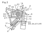
- Fig. 2 is a longitudinal sectional view of the linerless label roll-up preventing device 21 and Fig. 3 is an enlarged sectional view of the linerless label roll-up preventing device 21.
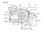
- Fig. 3 is an enlarged sectional view of the linerless label roll-up preventing device 21.
- the slit 22 is reaching the outer circumferential surface of a rotating shaft 24 of the platen roller 13 from the outer circumferential surface of the platen roller 13, and is formed the over the entire circumference of the rotating shaft 24. Furthermore, a pair of the slits 22 is formed at positions evenly located on right and left sides of the platen roller in the axial direction (symmetrical positions to the center portion in lengthwise of the platen roller 13), and a pair of the roll-up preventing plates 23 is provided at the slits 22 respectively.
- the roll-up preventing plate 23 has an arcuate fitting portion 25, and a pair of right and left fixing ends (a first fixing end 26, a second fixing end 27).
- the arcuate fitting portion 25 is fitted to the rotating shaft 24 while ensuring the rotation of the platen roller 13, and on its exterior portion, forms a roll-up preventing edge 29 which is almost in an isosceles triangle shape, such that it is located at a down stream side (outlet 16 direction side) than a contacting portion 28 of the thermal head 12 and the platen roller 13.
- the roll-up preventing edge 29, by being provided with a roll-up preventing contacting surface 29A along the transfer direction of the linerless label between the thermal head 12 and the platen roller 13 and projecting slightly from the outer circumferential surface of the platen roller 13 as a portion of the roll-up preventing plate 23, is capable of contacting the back surface (adhesive agent layer 9) of the linerless label 3.
- the first fixing end 26 and the second fixing end 27, by being located at both ends of the arcuate fitting portions 25, are capable of relatively fixing the roll-up preventing plate 23 to the platen roller 13.
- the first fixing portion 26 is projecting out from the outer circumferential surface of the platen roller 13 in a first direction which is different from the projecting direction of the roll-up preventing projection edge 29, and is capable of preventing forward direction rotation of the roll-up preventing plate 23 against the forward direction rotation (transfer direction rotation) of the platen roller 13.
- the second fixing portion 27 is projecting out from the outer circumferential surface of the platen roller 13 in a second direction which is different from the projecting direction of the roll-up preventing projection edge 29, and is capable of preventing counter rotation of the roll-up preventing plate 23 against the counter rotation (reverse transfer direction rotation) of the platen roller 13.
- a plurality of guide rollers 31 are provided, such that the linerless label 3 is guided to the transfer route 5 between the thermal head 12 and the platen roller 13.
- a label sensor 32 is provided between the platen roller 13 and the guide roller 31, a label sensor 32 is provided.
- the linerless label 3 which is transferred and supplied between the thermal head 12 and the platen roller 13 of the printing unit 6, is transferred by the rotation of the platen roller 13, printed with printing information according to the printing data at the thermal head 12, and headed toward the outlet 16.
- the thermal printer 20 is portable, it does not require much printing pressure, and together with some ingenuity of the print pattern, etc., it will not cause any problem in the printing performance.
Landscapes
- Electronic Switches (AREA)
- Handling Of Sheets (AREA)
- Handling Of Continuous Sheets Of Paper (AREA)
- Labeling Devices (AREA)
- Feeding Of Articles By Means Other Than Belts Or Rollers (AREA)
Abstract
Description
- Priority is claimed on Japanese Patent Application No.
2009-177986, filed July 30, 2009 - The present invention relates to a linerless label roll-up preventing device of a thermal printer. More particularly, the present invention relates to a linerless label roll-up preventing device of a thermal printer which performs printing by loading a linerless label.
- Previously, as a strip-form label sheet, there was a linerless label to save resources by not using a liner (peeling sheet) that is temporary attached to the adhesive layer on the back surface of the label base member. Printers for such a linerless label have also been developed.
Fig. 4 is a schematic side-view diagram of athermal printer 1, as an example of a conventional linerless label printer. Th ethermal printer 1 is, for example, configured to be portable having aprinter housing 2, a holding and supplyingunit 4 holding alinerless label 3 in a roll, aninternal transfer route 5, and aprinting unit 6. - By a belt 7 on the
printer housing 2, thethermal printer 1 can be portable, for example on the waist W of an operator. - The
linerless label 3, as shown enlarged in the diagram, has a strip-formlabel base member 8, an adhesive layer 9 formed on the back surface of thelabel base member 8, and a lower layer thermal color formingagent layer 10 and a upper layer separatingagent layer 11 formed on the surface of thelabel base member 8.
Therefore, if thelinerless label 3 is loaded in a roll at the holding and supplyingunit 4, since theseparating agent layer 11 is contacting the adhesive agent layer 9, the inner layer side and the outer layer side of the roll will not adhere with each other, and therefore it is possible to feed out the rolledlinerless label 3 in a strip-form to thetransfer route 5.
Furthermore, by forming perforations (not shown in the diagram) at a predetermined pitch on thelinerless label 3, it is possible to cut the printedlinerless label 3 in a predetermined size. - The
printing unit 6 has athermal head 12 and aplaten roller 13. Theprinting unit 6 supplies thelinerless label 3 between thethermal head 12 and theplaten roller 13, and transfers thelinerless label 3 by the rotating drive of theplaten roller 13 such that it is possible to perform printing of a predetermined contents on the surface of thelabel base member 8.
Furthermore, thethermal head 12 is provided at theprinter housing 2, and theplaten roller 13 is provided rotatably at an end portion of anopenable cover 15 around an opening-closing shaft 14 fixed on theprinter housing 2.
Thelinerless label 3 printed at theprinting unit 6 is discharged outside of theprinter housing 2 from thelabel outlet 16 of theprinter housing 2, cut at the perforations, and attached to the predetermined portion. - In the
thermal printer 1 having such a configuration, the parts of thetransfer route 5 and theplaten roller 13, etc., which contact the adhesive agent layer 9 at the back surface of thelinerless label 3 are ensured of non-adhesiveness by themselves, by the use of necessary separable material or by being provided with surface preparation such that the surface has detachability (non-adhesiveness). For example, silicone rubber is used for theplaten roller 13. - However, in a prolonged use of the
thermal printer 1 by its continuous use, the non-adhesiveness of theplaten roller 13 will deteriorate, so the adhesive agent (adhesive paste) of the adhesive agent layer 9 is gradually infiltrated into theplaten roller 13, and furthermore, the adhesive agent adheres to theplaten roller 13. Particularly as shown by the virtual line in the diagram, the printedlinerless label 3 is not transferring in theoutlet 16 direction, but with the rotation of theplaten roller 13, the printedlinerless label 3 is adhering to the outer circumferential surface of theplaten roller 13. As a result, it causes a problem in issuance and discharge of thelinerless label 3 since the label is being rolled-up around this outer circumferential surface. - The present invention has been made in view of the aforementioned problems. The object of the present invention is to provide a linerless label roll-up preventing device of a thermal printer which is not affected by the deterioration of non-adhesiveness of the platen roller due to its continuous usage and by the adhesiveness of the adhesive agent of the linerless label, and which is capable of preventing the roll-up of the linerless label to the platen roller.
- Another object of the present invention is to provide a linerless label roll-up preventing device of a thermal printer which can ensure stable transfer of the linerless label at the platen roller portion.
- Another object of the present invention is to provide a linerless label roll-up preventing device of a thermal printer which is capable of forcibly peeling off the linerless label adhered and rolled-up to the outer circumferential surface of the platen roller.
- Yet another object of the present invention is to provide a linerless label roll-up preventing device of a thermal printer which is capable of utilizing a common platen roller depending on the type of the adhesive agent of the linerless label, without employing an exclusive or a new platen roller which has been enhanced to improve the non-adhesiveness of the platen roller, and by employing the conventional parts as they are.
- The present invention focuses on forming slits with small width in the radial direction of the platen roller, attaching the roll-up preventing plate to the slits, and protrudingly forming the roll-up preventing projections at a portion of the roll-up preventing plate enabling to contact the adhesive agent layer side of the linerless label. A first aspect of the present invention includes: a linerless label roll-up preventing device of a thermal printer which supplies a linerless label formed with an adhesive agent layer on back side of a label base member and a separating agent layer on surface of the label base member between a thermal head and a platen roller, transfers the linerless label with rotation of the platen roller, and performs printing of a predetermined content on the surface of label base member, the linerless label roll-up preventing device comprising: a roll-up preventing plate capable of fixing to a slit, formed in the radial surface of the platen roller, relatively to the rotating platen roller; and formed with a roll-up preventing projection edge at a portion of the roll-up preventing plate, projecting out slightly from the outer circumferential surface of the platen roller, and capable of contacting the back surface of the linerless label.
- The roll-up preventing plate can be provided with an arcuate fitting portion, which is fitted to a rotating shaft of the platen roller, while ensuring rotation of the rotating shaft, and which forms, at its exterior portion, the roll-up preventing projection edge, such that it is located at a down stream side than the contacting portion of the thermal head and the platen roller between the thermal head and the platen roller; and a pair of right and left fixing ends, which are located at both ends of the arcuate fitting portion, and capable of fixing the roll-up preventing plates relatively to the platen roller.
- The fixing end can be provided with a first fixing end projecting out from the outer circumferential surface of the platen roller in a direction different from the projecting direction of the roll-up preventing projection edge, and capable of preventing forward direction rotation of the roll-up preventing plate against the forward direction rotation of the platen roller; and a second fixing end projecting from the outer circumferential surface of the platen roller in a direction different from the projecting direction of the roll-up preventing projection edge, and capable of preventing counter rotation of the roll-up preventing plate against the counter rotation of the platen roller.
- The roll-up preventing projection edge can be provided with a roll-up preventing contacting surface along a transfer direction of the linerless label between the thermal head and the platen roller.
- The slit is possible of reaching to the outer circumferential surface of the rotating shaft of the platen roller from the outer circumferential surface of the platen roller.
- A pair of the slits is formed at positions evenly located on right and left sides of the platen roller in the axial direction, and a pair of the roll-up preventing plates can be provided on the respective slits.
- The roll-up preventing plates are desirable to be configured with plastic members (such as polyacetal resin, etc.) having resistance to fatigue, resistance to deformation, resistance to abrasion, and resistance to heat, as well as detachability.
- On the surface of the label base member, it is desirable to form a thermal color forming agent layer on the lower layer of the separating agent layer, and perform printing by the thermal head.
- In a linerless label roll-up preventing device of a thermal printer of the present invention, the roll-up preventing plates are attached to the roll-up preventing slits formed in the radial surface of the platen roller, protruding to form the roll-up preventing projection edges which are capable of contacting the adhesive agent layer side of the linerless label at a portion of the roll-up preventing plates. Since the linerless label is transferred between the thermal head and the platen roller and printed, contacts the roll-up preventing projection edges, forcibly detached from the outer circumferential surface of the platen roller by running on to the roll-up preventing edges from the outer circumferential surface of the platen roller, and guided to the direction of the outlet, and particularly, by eliminating the influence from the deterioration of the non-adhesiveness of the platen roller and the adhesive agent of the linerless label, a stable transfer, issuance, discharge of the linerless label can be achieved..
-
-
Fig. 1 is a perspective view of thecover 15 of thethermal printer 20 equipped with the linerless label roll-up preventing device 21 according to the embodiment of the present invention. -
Fig. 2 is a longitudinal sectional view of the linerless label roll-up preventing device 21 according to the embodiment of the present invention. -
Fig. 3 is an enlarged sectional view of the linerless label roll-up preventing device 21 according to the embodiment of the present invention. -
Fig. 4 is a schematic side view of the conventional printer (thermal printer 1) of a linerless label. - According to the present invention, it is possible to achieve a linerless label roll-up preventing device of a thermal printer which is capable of stable transfer of the linerless label by preventing roll-up of the linerless label to the platen roller with forcible peeling action of the linerless label by the roll-up preventing projection edge protrudingly formed at a part of the roll-up preventing plate.
- Hereinafter, a linerless label roll-up preventing device of a thermal printer that is an embodiment of the present invention will be explained based on
Figs. 1 through 3 . However, the same reference numbers are used for those which are the same as those parts used inFig. 4 , and detailed explanation will be omitted.
Fig. 1 is a perspective view of the cover 15 (Fig. 4 ) of athermal printer 20. Thethermal printer 20, as same as the aforementioned thermal printer 1 (Fig. 4 ) has aprinter housing 2, a supplying andholding unit 4, atransfer route 5, aprinting unit 6, and acover 15, and also a roll-up preventing device 21 of alinerless label 3 at part of theprinting unit 6. - In other words, at the roll-
up preventing device 21 of thelinerless label 3, a pair of right andleft slits 22 having small width are formed in the radial surface (in the surface perpendicular to the axial direction) of aplaten roller 13 which is attached rotatably at the end portion of anopenable cover 15. -
Fig. 2 is a longitudinal sectional view of the linerless label roll-up preventing device 21 andFig. 3 is an enlarged sectional view of the linerless label roll-up preventing device 21. To theslits 22 of theplaten roller 13, roll-up preventingplates 23 which are capable of fixing relatively to the rotatingplaten roller 13 are provided. - The
slit 22, is reaching the outer circumferential surface of a rotatingshaft 24 of theplaten roller 13 from the outer circumferential surface of theplaten roller 13, and is formed the over the entire circumference of therotating shaft 24.
Furthermore, a pair of theslits 22 is formed at positions evenly located on right and left sides of the platen roller in the axial direction (symmetrical positions to the center portion in lengthwise of the platen roller 13), and a pair of the roll-up preventing plates 23 is provided at theslits 22 respectively. - The roll-
up preventing plate 23 has anarcuate fitting portion 25, and a pair of right and left fixing ends (afirst fixing end 26, a second fixing end 27).
Thearcuate fitting portion 25 is fitted to the rotatingshaft 24 while ensuring the rotation of theplaten roller 13, and on its exterior portion, forms a roll-up preventing edge 29 which is almost in an isosceles triangle shape, such that it is located at a down stream side (outlet 16 direction side) than a contactingportion 28 of thethermal head 12 and theplaten roller 13.
The roll-up preventing edge 29, by being provided with a roll-up preventing contactingsurface 29A along the transfer direction of the linerless label between thethermal head 12 and theplaten roller 13 and projecting slightly from the outer circumferential surface of theplaten roller 13 as a portion of the roll-up preventing plate 23, is capable of contacting the back surface (adhesive agent layer 9) of thelinerless label 3. - The
first fixing end 26 and thesecond fixing end 27, by being located at both ends of the arcuate fittingportions 25, are capable of relatively fixing the roll-up preventing plate 23 to theplaten roller 13.
Thefirst fixing portion 26 is projecting out from the outer circumferential surface of theplaten roller 13 in a first direction which is different from the projecting direction of the roll-up preventingprojection edge 29, and is capable of preventing forward direction rotation of the roll-up preventing plate 23 against the forward direction rotation (transfer direction rotation) of theplaten roller 13.
Thesecond fixing portion 27 is projecting out from the outer circumferential surface of theplaten roller 13 in a second direction which is different from the projecting direction of the roll-up preventingprojection edge 29, and is capable of preventing counter rotation of the roll-up preventing plate 23 against the counter rotation (reverse transfer direction rotation) of theplaten roller 13.
In other words, particularly as shown inFig. 3 , thefirst fixing portion 26, by theside bottom portion 26A in abutting contact with afirst stopper surface 30A of thestopper bracket 30 of thecover 15, controls the rotating movement of the roll-up preventing plate 23 around the rotatingshaft 24, in a counterclockwise rotation in the diagram (forward transfer direction of the linerless label).
Thesecond fixing portion 27, formed slightly longer than the first fixingportion 26, by theinner side portion 27A in abutting contact with asecond stopper surface 30B of thestopper bracket 30 of thecover 15, controls the rotating movement of the roll-up preventingplate 23 around the rotatingshaft 24, in a clockwise rotation (counter transfer direction of the linerless label). - Furthermore, as shown in
Fig. 1 , at the upper stream side of theplaten roller 13 of thecover 15, a plurality ofguide rollers 31 are provided, such that thelinerless label 3 is guided to thetransfer route 5 between thethermal head 12 and theplaten roller 13.
In addition, between theplaten roller 13 and theguide roller 31, alabel sensor 32 is provided. - In the
thermal printer 1 and the linerless label roll-up preventingdevice 21 with such configuration, thelinerless label 3 which is transferred and supplied between thethermal head 12 and theplaten roller 13 of theprinting unit 6, is transferred by the rotation of theplaten roller 13, printed with printing information according to the printing data at thethermal head 12, and headed toward theoutlet 16. - Even if the non-adhesiveness of the
platen roller 13 deteriorates, or if the adhesive agent of the adhesive agent layer 9 on thelinerless label 3 adheres to the outer circumferential surface of theplaten roller 13, without having thelinerless label 3 heading in a direction (in dotted arrowed line inFig. 3 ) where thelinerless label 3 rolls-up to theplaten roller 13 while being adhered to theplaten roller 13, and by forcibly peeling off the tip portion of thelinerless label 3 with the roll-up preventing projection edge 29 (roll-up preventing contactingsurface 29A) at the arcuatefitting portion 25 of the roll-up preventingplate 23, it is possible to guide thelinerless label 3 toward theoutlet 16 as shown in solid arrowed line inFig. 3 . - Thus, it is possible to reliably prevent rolling-up of the printed
linerless label 3 to theplaten roller 13, and ensuring stable transfer, printing, and issuance and discharging operations of thelinerless label 3. - Furthermore, by forming the
slits 22 on theplaten roller 13, there is a possibility of reducing the printing pressure put upon thelinerless label 3 transferred along theslit 22 portion. However, since thelinerless label 3, compared to a label with a liner, is provided with a rigidity of a predetermined level or more, and even if thelinerless label 3 passes over the portion of theslits 22, there will not be much effect by the printing pressure put upon thelinerless label 3. In case if thethermal printer 20 is portable, it does not require much printing pressure, and together with some ingenuity of the print pattern, etc., it will not cause any problem in the printing performance. -
- 1
- thermal printer 1 (
Fig. 4 ) - 2
- printer housing
- 3
- linerless label
- 4
- holding and supplying unit
- 5
- transfer route
- 6
- printing unit
- 7
- belt
- 8
- label base member
- 9
- adhesive agent layer
- 10
- thermal color forming agent layer
- 11
- separating agent layer
- 12
- thermal head
- 13
- platen roller
- 14
- opening-closing shaft
- 15
- cover
- 16
- outlet
- 20
- thermal printer (
Fig. 1 ) - 21
- linerless label roll-up preventing device of thermal printer 20 (Embodiment,
Figs. 1 through 3 ) - 22
- a pair of right and left slits
- 23
- a pair of right and left roll-up preventing plates
- 24
- rotating shaft of
platen roller 13 - 25
- arcuate fitting portion
- 26
- first fixing end
- 26A
- side bottom portion of first fixing end 26 (
Fig. 3 ) - 27
- second fixing end
- 27A
- inner side portion of second fixing end 27 (
Fig. 3 ) - 28
- contacting portion of
thermal head 12 and platen roller 13 (Fig. 3 ) - 29
- roll-up preventing projection edge
- 29A
- roll-up preventing contacting surface of roll-up preventing
projection edge 29 - 30
- stopper bracket
- 30A
- first stopper surface of
stopper bracket 30 - 30B
- second stopper surface of
stopper bracket 30 - 31
- guide roller (
Fig. 1 ) - 32
- label sensor
- W
- waist portion of operator (
Fig. 4 ) - Japanese Unexamined Patent Application First Publication No.
2005-47196
Claims (6)
- A linerless label roll-up preventing device of a thermal printer which supplies a linerless label formed with an adhesive agent layer on back side of a label base member and a separating agent layer on surface of the label base member between a thermal head and a platen roller, transfers the linerless label with rotation of the platen roller, and performs printing of a predetermined content on the surface of label base member,
the linerless label roll-up preventing device comprising:a roll-up preventing plate capable of fixing to a slit, formed in the radial surface of the platen roller, relatively to the rotating platen roller; and formed witha roll-up preventing projection edge at a portion of the roll-up preventing plate, projecting out slightly from the outer circumferential surface of the platen roller, and capable of contacting the back surface of the linerless label. - The linerless label roll-up preventing device of a thermal printer according to claim 1, wherein the roll-up preventing plate is provided with
an arcuate fitting portion, which is fitted to a rotating shaft of the platen roller, while ensuring rotation of the rotating shaft, and which forms, at its exterior portion, the roll-up preventing projection edge, such that it is located at a down stream side than the contacting portion of the thermal head and the platen roller between the thermal head and the platen roller; and
a pair of right and left fixing end, which are located at both ends of the arcuate fitting portion, and capable of fixing the roll-up preventing plates relatively to the platen roller. - The linerless label roll-up preventing device of a thermal printer according to claim 2, wherein the fixing end is provided with
a first fixing end projecting out from the outer circumferential surface of the platen roller in a direction different from the projecting direction of the roll-up preventing projection edge, and capable of preventing forward direction rotation of the roll-up preventing plate against the forward direction rotation of the platen roller; and
a second fixing end projecting from the outer circumferential surface of the platen roller in a direction different from the projecting direction of the roll-up preventing projection edge, and capable of preventing counter rotation of the roll-up preventing plate against the counter rotation of the platen roller. - The linerless label roll-up preventing device of a thermal printer according to claim 1, wherein the roll-up preventing projection edge is provided with
a roll-up preventing contacting surface along a transfer direction of the linerless label between the thermal head and the platen roller. - The linerless label roll-up preventing device of a thermal printer according to claim 1, wherein
the slit is reaching to the outer circumferential surface of the rotating shaft of the platen roller from the outer circumferential surface of the platen roller. - The linerless label roll-up preventing device of a thermal printer according to claim 1, wherein
a pair of the slits is formed at positions evenly located on right and left sides of the platen roller in the axial direction, and
a pair of the roll-up preventing plates is provided on the respective slits.
Applications Claiming Priority (2)
| Application Number | Priority Date | Filing Date | Title |
|---|---|---|---|
| JP2009177986A JP5351648B2 (en) | 2009-07-30 | 2009-07-30 | Mount prevention device for non-mounting label in thermal printer |
| PCT/JP2009/004140 WO2011013183A1 (en) | 2009-07-30 | 2009-08-26 | Device for preventing caught-in of label without mount in thermal printer |
Publications (3)
| Publication Number | Publication Date |
|---|---|
| EP2305482A1 true EP2305482A1 (en) | 2011-04-06 |
| EP2305482A4 EP2305482A4 (en) | 2013-08-28 |
| EP2305482B1 EP2305482B1 (en) | 2014-11-05 |
Family
ID=43528864
Family Applications (1)
| Application Number | Title | Priority Date | Filing Date |
|---|---|---|---|
| EP09840184.7A Not-in-force EP2305482B1 (en) | 2009-07-30 | 2009-08-26 | Device for preventing caught-in of label without mount in thermal printer |
Country Status (4)
| Country | Link |
|---|---|
| US (1) | US8379071B2 (en) |
| EP (1) | EP2305482B1 (en) |
| JP (1) | JP5351648B2 (en) |
| WO (1) | WO2011013183A1 (en) |
Cited By (3)
| Publication number | Priority date | Publication date | Assignee | Title |
|---|---|---|---|---|
| CN106132714A (en) * | 2014-03-31 | 2016-11-16 | 佐藤控股株式会社 | Anti-entrapment device for linerless label in thermal printer and method for setting label front end |
| CN106457850A (en) * | 2014-07-10 | 2017-02-22 | 佐藤控股株式会社 | printer |
| WO2018065022A1 (en) * | 2016-10-06 | 2018-04-12 | Gram Equipment A/S | Anti-wrapping device for a web pulling roll |
Families Citing this family (15)
| Publication number | Priority date | Publication date | Assignee | Title |
|---|---|---|---|---|
| JP2012136345A (en) * | 2010-12-28 | 2012-07-19 | Sato Knowledge & Intellectual Property Institute | Label roll-in prevention device |
| DE112012007377B4 (en) | 2011-02-16 | 2025-08-07 | Semiconductor Energy Laboratory Co., Ltd. | Light-emitting element |
| EP2910506B1 (en) | 2012-10-19 | 2018-07-18 | Sato Holdings Kabushiki Kaisha | Elastic body roller |
| JP5558618B1 (en) | 2013-10-09 | 2014-07-23 | サトーホールディングス株式会社 | Elastic roller |
| JP6324213B2 (en) | 2014-05-27 | 2018-05-16 | サトーホールディングス株式会社 | Elastic roller |
| JP6324212B2 (en) | 2014-05-27 | 2018-05-16 | サトーホールディングス株式会社 | Elastic roller |
| JP5852715B1 (en) | 2014-08-18 | 2016-02-03 | サトーホールディングス株式会社 | Printer |
| JP6408834B2 (en) * | 2014-08-29 | 2018-10-17 | サトーホールディングス株式会社 | Platen unit and printer |
| JP6422706B2 (en) | 2014-08-29 | 2018-11-14 | サトーホールディングス株式会社 | Elastic roller |
| JP6380977B2 (en) | 2014-08-29 | 2018-08-29 | サトーホールディングス株式会社 | Elastic roller |
| JP1521369S (en) * | 2014-09-29 | 2015-04-13 | ||
| JP1521368S (en) * | 2014-09-29 | 2015-04-13 | ||
| JP6121510B2 (en) * | 2015-12-04 | 2017-04-26 | サトーホールディングス株式会社 | Printer |
| USD837803S1 (en) * | 2017-05-02 | 2019-01-08 | Avision Inc. | Paper support |
| JP2019217635A (en) * | 2018-06-15 | 2019-12-26 | 富士通コンポーネント株式会社 | Printer device |
Family Cites Families (5)
| Publication number | Priority date | Publication date | Assignee | Title |
|---|---|---|---|---|
| US5674345A (en) * | 1992-07-01 | 1997-10-07 | Moore Business Forms, Inc. | Linerless label printer applicator |
| JPH06328794A (en) * | 1993-05-18 | 1994-11-29 | Canon Inc | Recording device |
| JP4188174B2 (en) | 2003-07-30 | 2008-11-26 | アイリスオーヤマ株式会社 | Laminator |
| US7186043B2 (en) * | 2004-04-08 | 2007-03-06 | Paxar Americas, Inc. | Linerless web utilizing apparatus and methods having dual function stripper element |
| JP4919979B2 (en) | 2008-01-28 | 2012-04-18 | 中国電力株式会社 | Line device |
-
2009
- 2009-07-30 JP JP2009177986A patent/JP5351648B2/en not_active Expired - Fee Related
- 2009-08-26 EP EP09840184.7A patent/EP2305482B1/en not_active Not-in-force
- 2009-08-26 WO PCT/JP2009/004140 patent/WO2011013183A1/en not_active Ceased
- 2009-08-26 US US12/991,276 patent/US8379071B2/en not_active Expired - Fee Related
Non-Patent Citations (2)
| Title |
|---|
| No further relevant documents disclosed * |
| See also references of WO2011013183A1 * |
Cited By (10)
| Publication number | Priority date | Publication date | Assignee | Title |
|---|---|---|---|---|
| CN106132714A (en) * | 2014-03-31 | 2016-11-16 | 佐藤控股株式会社 | Anti-entrapment device for linerless label in thermal printer and method for setting label front end |
| US20170173979A1 (en) * | 2014-03-31 | 2017-06-22 | Sato Holdings Kabushiki Kaisha | Roll-up prevention device and label tip setting method for linerless label in thermal printer |
| EP3127707A4 (en) * | 2014-03-31 | 2017-11-15 | Sato Holdings Kabushiki Kaisha | Device for preventing liner-free label from getting caught in thermal printer and method for putting leading edge of label in place |
| US9994051B2 (en) * | 2014-03-31 | 2018-06-12 | Sato Holdings Kabushiki Kaisha | Roll-up prevention device and label tip setting method for linerless label in thermal printer |
| CN106132714B (en) * | 2014-03-31 | 2018-11-16 | 佐藤控股株式会社 | Anti-entrapment device for linerless label in thermal printer and method for setting label front end |
| CN106457850A (en) * | 2014-07-10 | 2017-02-22 | 佐藤控股株式会社 | printer |
| EP3168050A4 (en) * | 2014-07-10 | 2018-02-28 | Sato Holdings Kabushiki Kaisha | Printer |
| KR101876821B1 (en) * | 2014-07-10 | 2018-07-10 | 사토 홀딩스 가부시키가이샤 | Printer |
| WO2018065022A1 (en) * | 2016-10-06 | 2018-04-12 | Gram Equipment A/S | Anti-wrapping device for a web pulling roll |
| US11401068B2 (en) | 2016-10-06 | 2022-08-02 | Gram Equipment A/S | Apparatus for packing articles and comprising a device for counteracting winding up of film |
Also Published As
| Publication number | Publication date |
|---|---|
| EP2305482A4 (en) | 2013-08-28 |
| US8379071B2 (en) | 2013-02-19 |
| US20110211034A1 (en) | 2011-09-01 |
| JP5351648B2 (en) | 2013-11-27 |
| WO2011013183A1 (en) | 2011-02-03 |
| JP2011031426A (en) | 2011-02-17 |
| EP2305482B1 (en) | 2014-11-05 |
Similar Documents
| Publication | Publication Date | Title |
|---|---|---|
| EP2305482B1 (en) | Device for preventing caught-in of label without mount in thermal printer | |
| US5779370A (en) | Apparatus for printing labels and a self-releasing print roller therefor | |
| KR102296437B1 (en) | Device for preventing liner-free label from getting caught in thermal printer and method for putting leading edge of label in place | |
| JP2007076721A (en) | Label peeling mechanism and printer | |
| JP6408834B2 (en) | Platen unit and printer | |
| JP2013193261A (en) | Platen roller and label printer | |
| WO2012090347A1 (en) | Device for preventing wrapping of label | |
| JP2008284738A (en) | Linerless label printing method and printing system | |
| CN211617073U (en) | Label printer | |
| JP5731264B2 (en) | Transfer roller and printer | |
| JP5311856B2 (en) | Label guide device for automatic labeling machine | |
| US11084304B2 (en) | Cassette including guide for restraining disengagement of tape | |
| JP5693119B2 (en) | Transfer roller and printer | |
| JP4513676B2 (en) | Label peeling mechanism and label printer | |
| JP4277853B2 (en) | Inkjet recording device | |
| EP1672606A3 (en) | Thermal activation apparatus and printer including the same | |
| JP5390176B2 (en) | Label guide mechanism and width guide member thereof in label sticking apparatus | |
| JP2016150805A (en) | Sheet carrier device and printing equipment | |
| JP2003073035A (en) | Printer | |
| JP4878892B2 (en) | Small adhesive label sheet | |
| JP2017030903A (en) | Elastic endless belt and elastic endless belt device | |
| JP2007212693A (en) | No-separator label | |
| JPH08319050A (en) | Paper discharge device for image forming device | |
| JP2004268297A (en) | Printing drum and stencil process printing device | |
| JP2009208853A (en) | Image forming device |
Legal Events
| Date | Code | Title | Description |
|---|---|---|---|
| PUAI | Public reference made under article 153(3) epc to a published international application that has entered the european phase |
Free format text: ORIGINAL CODE: 0009012 |
|
| 17P | Request for examination filed |
Effective date: 20100825 |
|
| AK | Designated contracting states |
Kind code of ref document: A1 Designated state(s): AT BE BG CH CY CZ DE DK EE ES FI FR GB GR HR HU IE IS IT LI LT LU LV MC MK MT NL NO PL PT RO SE SI SK SM TR |
|
| AX | Request for extension of the european patent |
Extension state: AL BA RS |
|
| RIN1 | Information on inventor provided before grant (corrected) |
Inventor name: KATAYAMA, TAMOTSU |
|
| DAX | Request for extension of the european patent (deleted) | ||
| A4 | Supplementary search report drawn up and despatched |
Effective date: 20130725 |
|
| RIC1 | Information provided on ipc code assigned before grant |
Ipc: B41J 11/057 20060101ALI20130719BHEP Ipc: B41J 3/407 20060101AFI20130719BHEP Ipc: B41J 11/04 20060101ALI20130719BHEP Ipc: B65C 11/02 20060101ALI20130719BHEP |
|
| REG | Reference to a national code |
Ref country code: DE Ref legal event code: R079 Ref document number: 602009027641 Country of ref document: DE Free format text: PREVIOUS MAIN CLASS: B41J0011040000 Ipc: B41J0011057000 |
|
| GRAP | Despatch of communication of intention to grant a patent |
Free format text: ORIGINAL CODE: EPIDOSNIGR1 |
|
| RIC1 | Information provided on ipc code assigned before grant |
Ipc: B65C 11/02 20060101ALI20140422BHEP Ipc: B65C 9/18 20060101ALI20140422BHEP Ipc: B41J 11/057 20060101AFI20140422BHEP Ipc: B41J 3/407 20060101ALI20140422BHEP |
|
| INTG | Intention to grant announced |
Effective date: 20140519 |
|
| RAP1 | Party data changed (applicant data changed or rights of an application transferred) |
Owner name: SATO HOLDINGS KABUSHIKI KAISHA |
|
| GRAS | Grant fee paid |
Free format text: ORIGINAL CODE: EPIDOSNIGR3 |
|
| GRAA | (expected) grant |
Free format text: ORIGINAL CODE: 0009210 |
|
| AK | Designated contracting states |
Kind code of ref document: B1 Designated state(s): AT BE BG CH CY CZ DE DK EE ES FI FR GB GR HR HU IE IS IT LI LT LU LV MC MK MT NL NO PL PT RO SE SI SK SM TR |
|
| REG | Reference to a national code |
Ref country code: GB Ref legal event code: FG4D |
|
| REG | Reference to a national code |
Ref country code: CH Ref legal event code: EP |
|
| REG | Reference to a national code |
Ref country code: AT Ref legal event code: REF Ref document number: 694390 Country of ref document: AT Kind code of ref document: T Effective date: 20141115 |
|
| REG | Reference to a national code |
Ref country code: IE Ref legal event code: FG4D |
|
| REG | Reference to a national code |
Ref country code: DE Ref legal event code: R096 Ref document number: 602009027641 Country of ref document: DE Effective date: 20141218 |
|
| REG | Reference to a national code |
Ref country code: AT Ref legal event code: MK05 Ref document number: 694390 Country of ref document: AT Kind code of ref document: T Effective date: 20141105 |
|
| REG | Reference to a national code |
Ref country code: NL Ref legal event code: VDEP Effective date: 20141105 |
|
| REG | Reference to a national code |
Ref country code: LT Ref legal event code: MG4D |
|
| PG25 | Lapsed in a contracting state [announced via postgrant information from national office to epo] |
Ref country code: LT Free format text: LAPSE BECAUSE OF FAILURE TO SUBMIT A TRANSLATION OF THE DESCRIPTION OR TO PAY THE FEE WITHIN THE PRESCRIBED TIME-LIMIT Effective date: 20141105 Ref country code: ES Free format text: LAPSE BECAUSE OF FAILURE TO SUBMIT A TRANSLATION OF THE DESCRIPTION OR TO PAY THE FEE WITHIN THE PRESCRIBED TIME-LIMIT Effective date: 20141105 Ref country code: FI Free format text: LAPSE BECAUSE OF FAILURE TO SUBMIT A TRANSLATION OF THE DESCRIPTION OR TO PAY THE FEE WITHIN THE PRESCRIBED TIME-LIMIT Effective date: 20141105 Ref country code: NO Free format text: LAPSE BECAUSE OF FAILURE TO SUBMIT A TRANSLATION OF THE DESCRIPTION OR TO PAY THE FEE WITHIN THE PRESCRIBED TIME-LIMIT Effective date: 20150205 Ref country code: PT Free format text: LAPSE BECAUSE OF FAILURE TO SUBMIT A TRANSLATION OF THE DESCRIPTION OR TO PAY THE FEE WITHIN THE PRESCRIBED TIME-LIMIT Effective date: 20150305 Ref country code: IS Free format text: LAPSE BECAUSE OF FAILURE TO SUBMIT A TRANSLATION OF THE DESCRIPTION OR TO PAY THE FEE WITHIN THE PRESCRIBED TIME-LIMIT Effective date: 20150305 Ref country code: NL Free format text: LAPSE BECAUSE OF FAILURE TO SUBMIT A TRANSLATION OF THE DESCRIPTION OR TO PAY THE FEE WITHIN THE PRESCRIBED TIME-LIMIT Effective date: 20141105 |
|
| PG25 | Lapsed in a contracting state [announced via postgrant information from national office to epo] |
Ref country code: PL Free format text: LAPSE BECAUSE OF FAILURE TO SUBMIT A TRANSLATION OF THE DESCRIPTION OR TO PAY THE FEE WITHIN THE PRESCRIBED TIME-LIMIT Effective date: 20141105 Ref country code: GR Free format text: LAPSE BECAUSE OF FAILURE TO SUBMIT A TRANSLATION OF THE DESCRIPTION OR TO PAY THE FEE WITHIN THE PRESCRIBED TIME-LIMIT Effective date: 20150206 Ref country code: AT Free format text: LAPSE BECAUSE OF FAILURE TO SUBMIT A TRANSLATION OF THE DESCRIPTION OR TO PAY THE FEE WITHIN THE PRESCRIBED TIME-LIMIT Effective date: 20141105 Ref country code: CY Free format text: LAPSE BECAUSE OF FAILURE TO SUBMIT A TRANSLATION OF THE DESCRIPTION OR TO PAY THE FEE WITHIN THE PRESCRIBED TIME-LIMIT Effective date: 20141105 Ref country code: HR Free format text: LAPSE BECAUSE OF FAILURE TO SUBMIT A TRANSLATION OF THE DESCRIPTION OR TO PAY THE FEE WITHIN THE PRESCRIBED TIME-LIMIT Effective date: 20141105 Ref country code: SE Free format text: LAPSE BECAUSE OF FAILURE TO SUBMIT A TRANSLATION OF THE DESCRIPTION OR TO PAY THE FEE WITHIN THE PRESCRIBED TIME-LIMIT Effective date: 20141105 Ref country code: LV Free format text: LAPSE BECAUSE OF FAILURE TO SUBMIT A TRANSLATION OF THE DESCRIPTION OR TO PAY THE FEE WITHIN THE PRESCRIBED TIME-LIMIT Effective date: 20141105 |
|
| PG25 | Lapsed in a contracting state [announced via postgrant information from national office to epo] |
Ref country code: SK Free format text: LAPSE BECAUSE OF FAILURE TO SUBMIT A TRANSLATION OF THE DESCRIPTION OR TO PAY THE FEE WITHIN THE PRESCRIBED TIME-LIMIT Effective date: 20141105 Ref country code: EE Free format text: LAPSE BECAUSE OF FAILURE TO SUBMIT A TRANSLATION OF THE DESCRIPTION OR TO PAY THE FEE WITHIN THE PRESCRIBED TIME-LIMIT Effective date: 20141105 Ref country code: CZ Free format text: LAPSE BECAUSE OF FAILURE TO SUBMIT A TRANSLATION OF THE DESCRIPTION OR TO PAY THE FEE WITHIN THE PRESCRIBED TIME-LIMIT Effective date: 20141105 Ref country code: RO Free format text: LAPSE BECAUSE OF FAILURE TO SUBMIT A TRANSLATION OF THE DESCRIPTION OR TO PAY THE FEE WITHIN THE PRESCRIBED TIME-LIMIT Effective date: 20141105 Ref country code: DK Free format text: LAPSE BECAUSE OF FAILURE TO SUBMIT A TRANSLATION OF THE DESCRIPTION OR TO PAY THE FEE WITHIN THE PRESCRIBED TIME-LIMIT Effective date: 20141105 |
|
| REG | Reference to a national code |
Ref country code: DE Ref legal event code: R097 Ref document number: 602009027641 Country of ref document: DE |
|
| PLBE | No opposition filed within time limit |
Free format text: ORIGINAL CODE: 0009261 |
|
| STAA | Information on the status of an ep patent application or granted ep patent |
Free format text: STATUS: NO OPPOSITION FILED WITHIN TIME LIMIT |
|
| 26N | No opposition filed |
Effective date: 20150806 |
|
| PG25 | Lapsed in a contracting state [announced via postgrant information from national office to epo] |
Ref country code: IT Free format text: LAPSE BECAUSE OF FAILURE TO SUBMIT A TRANSLATION OF THE DESCRIPTION OR TO PAY THE FEE WITHIN THE PRESCRIBED TIME-LIMIT Effective date: 20141105 |
|
| PG25 | Lapsed in a contracting state [announced via postgrant information from national office to epo] |
Ref country code: SI Free format text: LAPSE BECAUSE OF FAILURE TO SUBMIT A TRANSLATION OF THE DESCRIPTION OR TO PAY THE FEE WITHIN THE PRESCRIBED TIME-LIMIT Effective date: 20141105 |
|
| PG25 | Lapsed in a contracting state [announced via postgrant information from national office to epo] |
Ref country code: LU Free format text: LAPSE BECAUSE OF FAILURE TO SUBMIT A TRANSLATION OF THE DESCRIPTION OR TO PAY THE FEE WITHIN THE PRESCRIBED TIME-LIMIT Effective date: 20150826 Ref country code: MC Free format text: LAPSE BECAUSE OF FAILURE TO SUBMIT A TRANSLATION OF THE DESCRIPTION OR TO PAY THE FEE WITHIN THE PRESCRIBED TIME-LIMIT Effective date: 20141105 |
|
| REG | Reference to a national code |
Ref country code: CH Ref legal event code: PL |
|
| PG25 | Lapsed in a contracting state [announced via postgrant information from national office to epo] |
Ref country code: CH Free format text: LAPSE BECAUSE OF NON-PAYMENT OF DUE FEES Effective date: 20150831 Ref country code: LI Free format text: LAPSE BECAUSE OF NON-PAYMENT OF DUE FEES Effective date: 20150831 |
|
| REG | Reference to a national code |
Ref country code: IE Ref legal event code: MM4A |
|
| REG | Reference to a national code |
Ref country code: FR Ref legal event code: PLFP Year of fee payment: 8 |
|
| PG25 | Lapsed in a contracting state [announced via postgrant information from national office to epo] |
Ref country code: IE Free format text: LAPSE BECAUSE OF NON-PAYMENT OF DUE FEES Effective date: 20150826 |
|
| PG25 | Lapsed in a contracting state [announced via postgrant information from national office to epo] |
Ref country code: MT Free format text: LAPSE BECAUSE OF FAILURE TO SUBMIT A TRANSLATION OF THE DESCRIPTION OR TO PAY THE FEE WITHIN THE PRESCRIBED TIME-LIMIT Effective date: 20141105 |
|
| PG25 | Lapsed in a contracting state [announced via postgrant information from national office to epo] |
Ref country code: HU Free format text: LAPSE BECAUSE OF FAILURE TO SUBMIT A TRANSLATION OF THE DESCRIPTION OR TO PAY THE FEE WITHIN THE PRESCRIBED TIME-LIMIT; INVALID AB INITIO Effective date: 20090826 Ref country code: BG Free format text: LAPSE BECAUSE OF FAILURE TO SUBMIT A TRANSLATION OF THE DESCRIPTION OR TO PAY THE FEE WITHIN THE PRESCRIBED TIME-LIMIT Effective date: 20141105 Ref country code: SM Free format text: LAPSE BECAUSE OF FAILURE TO SUBMIT A TRANSLATION OF THE DESCRIPTION OR TO PAY THE FEE WITHIN THE PRESCRIBED TIME-LIMIT Effective date: 20141105 |
|
| REG | Reference to a national code |
Ref country code: FR Ref legal event code: PLFP Year of fee payment: 9 |
|
| PG25 | Lapsed in a contracting state [announced via postgrant information from national office to epo] |
Ref country code: TR Free format text: LAPSE BECAUSE OF FAILURE TO SUBMIT A TRANSLATION OF THE DESCRIPTION OR TO PAY THE FEE WITHIN THE PRESCRIBED TIME-LIMIT Effective date: 20141105 |
|
| PG25 | Lapsed in a contracting state [announced via postgrant information from national office to epo] |
Ref country code: BE Free format text: LAPSE BECAUSE OF FAILURE TO SUBMIT A TRANSLATION OF THE DESCRIPTION OR TO PAY THE FEE WITHIN THE PRESCRIBED TIME-LIMIT Effective date: 20141105 |
|
| PG25 | Lapsed in a contracting state [announced via postgrant information from national office to epo] |
Ref country code: MK Free format text: LAPSE BECAUSE OF FAILURE TO SUBMIT A TRANSLATION OF THE DESCRIPTION OR TO PAY THE FEE WITHIN THE PRESCRIBED TIME-LIMIT Effective date: 20141105 |
|
| REG | Reference to a national code |
Ref country code: FR Ref legal event code: PLFP Year of fee payment: 10 |
|
| PGFP | Annual fee paid to national office [announced via postgrant information from national office to epo] |
Ref country code: DE Payment date: 20200713 Year of fee payment: 12 Ref country code: GB Payment date: 20200729 Year of fee payment: 12 Ref country code: FR Payment date: 20200716 Year of fee payment: 12 |
|
| REG | Reference to a national code |
Ref country code: DE Ref legal event code: R119 Ref document number: 602009027641 Country of ref document: DE |
|
| GBPC | Gb: european patent ceased through non-payment of renewal fee |
Effective date: 20210826 |
|
| PG25 | Lapsed in a contracting state [announced via postgrant information from national office to epo] |
Ref country code: GB Free format text: LAPSE BECAUSE OF NON-PAYMENT OF DUE FEES Effective date: 20210826 Ref country code: FR Free format text: LAPSE BECAUSE OF NON-PAYMENT OF DUE FEES Effective date: 20210831 Ref country code: DE Free format text: LAPSE BECAUSE OF NON-PAYMENT OF DUE FEES Effective date: 20220301 |