EP2305467B1 - Improvements relating to screen printing apparatus - Google Patents
Improvements relating to screen printing apparatus Download PDFInfo
- Publication number
- EP2305467B1 EP2305467B1 EP10012032.8A EP10012032A EP2305467B1 EP 2305467 B1 EP2305467 B1 EP 2305467B1 EP 10012032 A EP10012032 A EP 10012032A EP 2305467 B1 EP2305467 B1 EP 2305467B1
- Authority
- EP
- European Patent Office
- Prior art keywords
- printing
- print module
- workpiece
- selected print
- screen
- Prior art date
- Legal status (The legal status is an assumption and is not a legal conclusion. Google has not performed a legal analysis and makes no representation as to the accuracy of the status listed.)
- Expired - Lifetime
Links
- 238000007650 screen-printing Methods 0.000 title claims description 25
- 238000007639 printing Methods 0.000 claims abstract description 151
- 239000000463 material Substances 0.000 claims abstract description 30
- 238000000034 method Methods 0.000 claims abstract description 16
- 230000007246 mechanism Effects 0.000 claims description 10
- 238000004140 cleaning Methods 0.000 claims description 5
- 230000008878 coupling Effects 0.000 description 8
- 238000010168 coupling process Methods 0.000 description 8
- 238000005859 coupling reaction Methods 0.000 description 8
- 230000008901 benefit Effects 0.000 description 3
- 238000004519 manufacturing process Methods 0.000 description 3
- 239000000758 substrate Substances 0.000 description 3
- 239000004020 conductor Substances 0.000 description 2
- 230000000712 assembly Effects 0.000 description 1
- 238000000429 assembly Methods 0.000 description 1
- 238000010276 construction Methods 0.000 description 1
- 230000004048 modification Effects 0.000 description 1
- 238000012986 modification Methods 0.000 description 1
- 150000003071 polychlorinated biphenyls Chemical class 0.000 description 1
Images

Classifications
-
- H—ELECTRICITY
- H05—ELECTRIC TECHNIQUES NOT OTHERWISE PROVIDED FOR
- H05K—PRINTED CIRCUITS; CASINGS OR CONSTRUCTIONAL DETAILS OF ELECTRIC APPARATUS; MANUFACTURE OF ASSEMBLAGES OF ELECTRICAL COMPONENTS
- H05K3/00—Apparatus or processes for manufacturing printed circuits
- H05K3/10—Apparatus or processes for manufacturing printed circuits in which conductive material is applied to the insulating support in such a manner as to form the desired conductive pattern
- H05K3/12—Apparatus or processes for manufacturing printed circuits in which conductive material is applied to the insulating support in such a manner as to form the desired conductive pattern using thick film techniques, e.g. printing techniques to apply the conductive material or similar techniques for applying conductive paste or ink patterns
- H05K3/1216—Apparatus or processes for manufacturing printed circuits in which conductive material is applied to the insulating support in such a manner as to form the desired conductive pattern using thick film techniques, e.g. printing techniques to apply the conductive material or similar techniques for applying conductive paste or ink patterns by screen printing or stencil printing
-
- B—PERFORMING OPERATIONS; TRANSPORTING
- B41—PRINTING; LINING MACHINES; TYPEWRITERS; STAMPS
- B41F—PRINTING MACHINES OR PRESSES
- B41F15/00—Screen printers
- B41F15/08—Machines
- B41F15/0804—Machines for printing sheets
- B41F15/0813—Machines for printing sheets with flat screens
-
- B—PERFORMING OPERATIONS; TRANSPORTING
- B41—PRINTING; LINING MACHINES; TYPEWRITERS; STAMPS
- B41P—INDEXING SCHEME RELATING TO PRINTING, LINING MACHINES, TYPEWRITERS, AND TO STAMPS
- B41P2215/00—Screen printing machines
- B41P2215/10—Screen printing machines characterised by their constructional features
- B41P2215/11—Registering devices
- B41P2215/112—Registering devices with means for displacing the frame
Definitions
- the present invention relates to a screen printing apparatus for and method of screen printing predeterminable patterns of material deposits onto workpieces, in particular, though not exclusively, electronic components such as circuit boards and the like.
- Such circuit boards typically comprise a printed circuit board (PCB) or substrate on which various electronic components are mounted and connected to conductive tracks by an electrically-conductive material provided thereon in a predetermined pattern.
- PCB printed circuit board
- an electrically-conductive material is printed on the printed circuit board or substrate through a printing screen.
- electronic components are then mounted to the printed circuit board or substrate such that those components are connected to the conductive tracks to form an electric circuit.
- Figure 3 illustrates a known screen printing apparatus.
- the apparatus comprises a substantially immobile printing screen 203 and a print head 205 which is movable back and forth across the printing screen 203 along a Y axis to drive printing material through a pattern in the printing screen 203 and onto a workpiece disposed therebelow.
- the apparatus further comprises a workpiece transport device which includes a pair of transport rails 207, 209 along which workpieces are transported to the printing zone, and a workpiece support mechanism 211 disposed beneath the printing screen 203.
- the apparatus further comprises a video camera 213 which is movable along X and Y axes to position the camera 213 at known positions between the workpiece and the printing screen 203 to measure any misalignment of the workpiece and the printing screen 203.
- positioning actuators are operated as required to correctly align the workpiece with the printing screen 203 before printing commences.
- X axis, Y axis and ⁇ axis positioning actuators are provided to translate or rotate the printing screen 203. as required, and correctly align the printing screen 203 with the workpiece disposed therebelow.
- any movement of the printing screen 203 is limited to less than 10 mm or 1.5 degrees, and is purely for aligning the printing screen 203 with a workpiece to be printed.
- a further disadvantage is that the prior art screen printing apparatus is of fixed size, each one being limited to printing onto a particular range of workpiece sizes, typically to a range of workpieces that are smaller than the printing screen.
- the prior art screen printing apparatus is also limited to printing onto planar workpieces, as the printing screen is only movable to a limited extent in X, Y and ⁇ axes. As electronic devices become smaller, it is envisaged that printing of non-planar workpieces may be required; such printing of non-planar workpieces not being possible with the prior art apparatus.
- US-A-4063501 discloses a removable module carrying a screen for a screen printing machine.
- the present invention provides a method of printing a predeterminable pattern of deposits of printing material onto a workpiece, the method comprising the steps of: selecting a first print module; positioning the first-selected print module in a predeterminable position above the workpiece in a printing zone; printing deposits of printing material onto a workpiece using the first-selected print module; returning the first-selected print module; selecting a second print module; positioning the second-selected print module in a predeterminable position above the workpiece in the printing zone; and printing deposits of printing material onto the workpiece using the second-selected print module.
- the present invention also provides a screen printing apparatus for printing a predeterminable pattern of deposits of printing material onto a workpiece
- the screen printing apparatus comprising: a plurality of print modules, each comprising, as a unitary assembly, a printing screen, a print head movable across the printing screen, and a drive mechanism for moving the print head with respect to the printing screen; and a positioning unit for positioning, in succession, a first-selected print module in a predeterminable position above the workpiece in a printing zone and a second-selected print module in a predeterminable position above the workpiece in the printing zone.
- the present invention also extends to a screen printing apparatus comprising a plurality of the above-described print modules, each having a different function, and movement means for selecting and moving the print modules.
- the apparatus further comprises a controller for selecting and interchanging the print modules from the printing zone.
- the present invention also relates to the use of a printing screen in a screen printing apparatus for printing a predeterminable pattern of deposits of printing material onto a workpiece, wherein the printing screen has a smaller lateral dimension than that of the workpiece.
- the present invention further relates to the use of a print module, comprising, as a unitary assembly, a printing screen and a print head movable across the printing screen, for printing a predeterminable pattern of deposits of printing material onto a workpiece.
- the printing screen can be easily cleaned by lifting the print module from the workpiece and wiping the same on a cleaning station to remove any excess printing material and other debris from the printing screen. Once clean, the print module can be returned for further printing operations.
- the screen printing apparatus is provided as part of a kit which comprises a plurality of detachable and interchangeable units, such as, for example, a screen printing unit and a component placement unit, means for selecting one or more of the units and respective moving means for moving the one or more selected units with respect to a workpiece.
- a kit which comprises a plurality of detachable and interchangeable units, such as, for example, a screen printing unit and a component placement unit, means for selecting one or more of the units and respective moving means for moving the one or more selected units with respect to a workpiece.
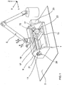
- Figure 1 illustrates a screen printing apparatus in accordance with a first embodiment of the present invention.
- the apparatus comprises a print module 1 for printing a pattern of deposits of a printing material on a workpiece 3, in this embodiment a circuit board, an articulated, robotic positioning arm 5 for positioning the print module 1 on the workpiece 3, and a controller for controlling the print module 1 and the robotic arm 5.
- the apparatus further comprises a workpiece transport device for transporting workpieces 3 to a printing zone in which the print module 1 is operable to print material deposits on a respective workpiece 3.
- the workpiece transport device includes a pair of guide rails along which workpieces 3 are transported to the printing zone.
- the print module 1 is a unitary assembly which comprises a housing 9, a printing screen 11 which is mounted to the housing 9, a print head 13 which is movably disposed relative to the housing 9 to apply printing material to the printing screen 11 and print material deposits on the workpiece 3, and a carriage assembly 15 for supporting and driving the print head 13 over the printing screen 11.
- the print head 13 comprises a squeegee print head or a pressure-driven print head as disclosed, for example, in WO-A-98/16387 .
- the print head 13 is a pressure-driven print head; such a print head 13 advantageously allowing for the printing of inverted workpieces 3.
- the carriage assembly 15 comprises a pair of guide rails 17, 17 which are mounted to the housing 9, a support block 19 which is slideably disposed to the guide rails 17, 17 and supports the print head 13, and a drive unit 20 which includes a motor-driven continuous drive belt 21 for driving the support block 19 and hence the print head 13 over the printing screen 11.
- the carriage assembly 15 could be driven by a worm drive, a pulley system or any other conventional drive mechanism.
- the carriage assembly 15 further comprises at least one actuator 22 for biasing the print head 13 into pressure contact with the printing screen 11 during printing.
- the print module 1 further comprises an alignment system 23 for aligning the print module 1 to the workpiece 3 as required.
- the alignment system 23 includes a video camera for locating fiducials or other locating indicators on the workpiece 3.
- One suitable system is disclosed in WO-A-95/14575 and US-A-5752446 .
- the print module 1 is detachable, preferably automatically, from the robotic arm 5 such that different print modules 1, for example, with differently patterned and/or sized printing screens 11, can be interchanged as required.
- the print module 1 could be interchanged for each print run, potentially comprising a single workpiece 3, to allow for the printing of different patterns and/or differently-sized workpieces 3.
- the print module 1 could be interchanged to allow for the printing of a plurality of different patterns and/or pattern sizes on a single workpiece 3. It is a particular advantage that the print module 1 can be readily interchanged, allowing for the use of print modules 1 having different screen patterns and/or screen sizes.
- the print module 1 has a significantly smaller lateral dimension than the workpiece 3.
- the print module 1 can, for example, be operated to print in a recess in the surface of the workpiece 3, which recess would not be accessible when using a printing screen 11 having the same lateral dimension as the workpiece 3, and also print a plurality of different patterns on the same workpiece 3.
- the present invention thus enables different combinations of circuit patterns to be printed easily and rapidly on a workpiece 3 without the need for dedicated printing screens 11 for each of the particular combinations of circuit patterns.
- the print module 1 could have a lateral dimension the same size or greater than the workpiece 3.
- the robotic arm 5 is configured to provide for movement of the print module 1 in the X. Y and Z axes, which movement allows for the positioning of the print module 1 on the surface of the workpiece 3.
- the robotic arm 5 is configured to provide for angular rotation ⁇ , ⁇ , ⁇ of the print module 1 about each of the X. Y and Z axes.
- angular rotation ⁇ about the Z axis, that is, an axis perpendicular to the plane of the printing screen 11.
- a pattern in the printing screen 11 can be deposited with any orient on a planar surface of the workpiece 3.
- the print module 1 can be translated and rotated to any position in space and allows for printing onto non-planar surfaces.
- the robotic arm 5 is attached to the print module 1 by a mechanical connection.
- the robotic arm 5 includes a clamp and the print module I includes a structural feature, for example, a a protrusion or a handle, which is engaged by the clamp on the robotic arm 5.
- the print module 1 includes a clamp and the robotic arm 5 includes a structural feature, for example, a protrusion or a handle, which is engaged by the clamp on the print module 1.
- the robotic arm 5 can be attached to the print module 1 by a magnetic connection.
- the robotic arm 5 could include an electromagnet which is magnetically clamped to the print module 1.
- the print module 1 could include an electromagnet which is magnetically clamped to the robotic arm 5.
- the controller is a programmable computer.
- the controller can be programmed to position the print module 1 at the required position or sequentially at the required positions and control the operation of the print module 1.
- the controller is programmed to operate the workpiece transport device to inwardly transport a workpiece 3 to the printing zone, and then operate the robotic arm 5 first to pick up a selected print module 1 from a store in an acquiring step, position the selected print module 1 in a predetermined position above the workpiece 3, and then, in a printing step, move the selected print module 1 into abutment with the workpiece 3 and drive the print head 13 across the printing screen 11 to deposit a pattern of deposits of printing material onto the workpiece 3.
- the printing step can then be repeated on further workpieces 3 until a given print run is completed.
- a new workpiece 3 to be printed is transported to the printing zone and a printed workpiece 3 is transported from the printing zone.
- the print module 1 is then returned to the store by the robotic arm 5 under the control of the controller.
- a different print module 1. for example, with a differently-patterned printing screen 11. could be picked up by the robotic arm 5, whereupon the above steps would then be repeated to provide a print run of workpieces 3 having the different printed pattern thereon.
- the printing steps may be interrupted with a cleaning step in which the print module 1 is moved to a cleaning station and the printing screen 11 wiped clean, as required.
- the controller is programmed to operate the workpiece transport device to inwardly transport a workpiece 3 to the printing zone, and then operate the robotic arm 5 to in turn select and operate a plurality of different print modules 1 to achieve the required pattern of deposits of printing material, with the operation of each of the print modules 1 being as described hereinabove.
- the controller is programmable "on-the-fly" so that new instructions can be inputted, for example, for a print run requiring yet another print module 1, without having to interrupt the current print run.
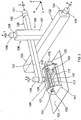
- Figure 2 illustrates a screen printing apparatus in accordance with a second embodiment of the present invention. This embodiment utilises a Cartesian positioning system.
- the apparatus comprises a print module 101 for printing a pattern of deposits of a printing material on a workpiece 103, a positioning assembly 105 for positioning the print module 101 on the workpiece 103, and a controller for controlling the print module 101 and the positioning assembly 105.
- the apparatus further comprises a workpiece transport device for transporting workpieces 103 to a printing zone in which the print module 101 is operable to print material deposits on a respective workpiece 103.
- the workpiece transport device includes a pair of guide rails along which workpieces 103 are transported to the printing zone.
- the print module 101 is a unitary assembly which comprises a housing 109, a printing screen 111 which is mounted to the housing 109, a print head 113 which is movably disposed relative to the housing 109 to apply printing material to the printing screen 111 and print material deposits on the workpiece 103, and a carriage assembly 115 for supporting and driving the print head 13 over the printing screen 111.
- the print head 113 comprises a squeegee print head or a pressure-driven print head as disclosed, for example, in WO-A-98/16387 .
- the print head 113 is a pressure-driven print head; such a print head 113 advantageously allowing for the printing of inverted workpieces 103.
- the carriage assembly 115 comprises a pair of guide rails 117, 117 which are mounted to the housing 109, a support block 119 which is slideably disposed to the guide rails 117, 117 and supports the print head 113, and a drive unit 120 which includes a motor-driven continuous drive belt 121 for driving the support block 119 and hence the print head 113 over the printing screen 111.
- the carriage assembly 115 could be driven by a worm drive, a pulley system or any other conventional drive mechanism.
- the carriage assembly 115 further comprises at least one actuator 122 for biasing the print head 113 into pressure contact with the printing screen 111 during printing.
- the print module 101 further comprises an alignment system 123 for aligning the print module 101 to the workpiece 103 as required.
- the alignment system 123 includes a video camera for locating fiducials or other locating indicators on the workpiece 103.
- One suitable system is disclosed in WO-A-95/14575 and US-A-5752446 .
- the print module 101 is detachable, preferably automatically, from the positioning assembly 105 such that different print modules 101, for example, with differently patterned and/or sized printing screens 111, can be interchanged as required.
- the print module 101 could be interchanged for each print run, potentially comprising a single workpiece 103, to allow for the printing of different patterns and/or differently-sized workpieces 103.
- the print module 101 could be interchanged to allow for the printing of a plurality of different patterns and/or pattern sizes on a single workpiece 103. It is a particular advantage that the print module 101 can be readily interchanged, allowing for the use of print modules 101 having different screen patterns and/or screen sizes.
- the print module 101 has a significantly smaller lateral dimension than the workpiece 103.
- the print module 101 can be operated to print in a recess in the surface of the workpiece 103, which recess would not be accessible when using a printing screen 111 having the same lateral dimension as the workpiece 103, and also print a plurality of different patterns on the same workpiece 103.
- the present invention thus enables different combinations of circuit patterns to be printed easily and rapidly on a workpiece 103 without the need for dedicated printing screens 111 for each of the particular combinations of circuit patterns.
- the print module 101 could have a lateral dimension the same size or greater than the workpiece 103.
- the positioning assembly 105 is configured to provide for movement of the print module 101 in the X. Y and Z axes, which movement allows for the positioning of the print module 101 on the surface of the workpiece 103.
- the positioning assembly 105 includes an arm unit 126 which comprises an arm 127 which extends in a direction substantially parallel to the Y axis, a coupling 128 which is disposed at the distal end of the arm 127 and to which the print module 101 is mounted, a first arm drive member 129, in this embodiment a motor, for providing angular rotation ⁇ of the print module 101 relative to the arm 127 about the Z axis, a second arm drive member 130, in this embodiment a motor, for driving the arm 127 and hence translating the print module 101 in the Y axis, and a third arm drive member 131, in this embodiment a motor, for providing angular rotation ⁇ of the arm 127 and hence the print module 101 about the Y axis.
- an arm unit 126 which comprises an arm 127 which extends in a direction substantially parallel to the Y axis, a coupling 128 which is disposed at the distal end of the arm 127 and to which the print module 101 is mounted, a first arm drive member 129
- the coupling 128 of the arm unit 126 of the positioning assembly 105 is attached to the print module 101 by a mechanical connection.
- the coupling 128 includes a clamp and the print module 101 includes a structural feature, for example, a protrusion or a handle, which is engaged by the clamp on the coupling 128.
- the print module 101 includes a clamp and the coupling 128 includes a structural feature, for example, a protrusion or a handle, which is engaged by the clamp on the print module 1.
- the coupling 128 on the arm unit 126 of the positioning assembly 105 can be attached to the print module 101 by a magnetic connection.
- the coupling 128 could include an electromagnet which is magnetically clamped to the print module 101.
- the print module 101 could include an electromagnet which is magnetically clamped to the coupling 128.
- the positioning assembly 105 further includes a beam unit 132 which comprises a beam 133 which extends in a direction substantially parallel to the X axis and to which the arm 127 of the arm unit 126 is movably disposed, a first beam drive member 134, in this embodiment a motor, for driving the beam 133 and hence translating the print module 101 in the X axis, and a second beam drive member 135 for providing angular rotation ⁇ of the beam 133 and hence the print module 101 about the X axis.
- a beam unit 132 which comprises a beam 133 which extends in a direction substantially parallel to the X axis and to which the arm 127 of the arm unit 126 is movably disposed, a first beam drive member 134, in this embodiment a motor, for driving the beam 133 and hence translating the print module 101 in the X axis, and a second beam drive member 135 for providing angular rotation ⁇ of the beam 133 and hence the print module 101 about the X axis.
- the positioning assembly 105 further includes a pillar unit 136 which comprises a pillar 137 which extends in a direction substantially parallel to the Z axis and to which the beam 133 is movably disposed, a first pillar drive member 138, in this embodiment a motor, for driving the pillar 137 and hence translating the print module 101 in the Z axis, and a second pillar drive member 139 for providing angular rotation ⁇ of the pillar 137 about the Z axis and hence rotate the print module 101 in an arc about the Z axis.
- a pillar unit 136 which comprises a pillar 137 which extends in a direction substantially parallel to the Z axis and to which the beam 133 is movably disposed, a first pillar drive member 138, in this embodiment a motor, for driving the pillar 137 and hence translating the print module 101 in the Z axis, and a second pillar drive member 139 for providing angular rotation ⁇ of the pillar 137 about the Z axis and hence rotate
- angular rotation ⁇ of the print module 101 about the Z axis that is, an axis perpendicular to the plane of the printing screen 111
- a pattern in the printing screen 111 can be deposited with any orient on a planar surface.
- angular rotation ⁇ , ⁇ about the X and Y axes the print module 101 can be translated and rotated to any position in space and allows for the printing onto non-planar surfaces.
- the controller is a programmable computer.
- the controller can be programmed to position the print module 1 at the required position or sequentially at the required positions and control the operation of the print module 1.
- the controller is programmed to operate the workpiece transport device to inwardly transport a workpiece 103 to the printing zone, and then operate the positioning assembly 105 first to pick up a selected print module 101 from a store in an acquiring step, position the selected print module 101 in a predetermined position above the workpiece 103, and then, in a printing step, move the selected print module 101 into abutment with the workpiece 103 and drive the print head 113 across the printing screen 111 to deposit a pattern of deposits of printing material onto the workpiece 103.
- the printing step can then be repeated on further workpieces 103 until a given print run is completed.
- a new workpiece 103 to be printed is transported to the printing zone and a printed workpiece 103 is transported from the printing zone.
- the print module 101 is then returned to the store by the positioning assembly 105 under the control of the controller.
- a different print module 101 for example, with a differently-patterned printing screen 111, could be picked up by the positioning assembly 105, whereupon the above steps would then be repeated to provide a print run of workpieces 103 having the different printed pattern thereon.
- the printing steps may be interrupted with a cleansing step in which the print module 101 is moved to a cleansing station and the printing screen 111 wiped clean, as required.
- the controller is programmed to operate the workpiece transport device to inwardly transport a workpiece 103 to the printing zone, and then operate the positioning assembly 105 to in turn select and operate a plurality of different print modules 101 to achieve the required pattern of deposits of printing material, with the operation of each of the print modules 101 being as described hereinabove.
- the controller is programmable "on-the-fly" so that new instructions can be inputted, for example, for a print run requiring yet another print module 10.1, without having to interrupt the current print run.
- various other mechanisms can be utilised to position the print module 1. 101.
- the only necessary movement of the print module 1. 101 is in the X, Y and Z directions, with angular rotation ⁇ of the print module 1, 101 about the Z axis, that is, an axis perpendicular to the printing screen 11, 111, being preferable.
- the apparatus could include first and second robotic arms 5 or positioning assemblies 105 for separately positioning and operating the printing screen 11, 111 and the print head 13, 113.
- the screen printing apparatus of the present invention need not be used alone as a dedicated screen printer, but could be incorporated in other equipment.
- the screen printing apparatus could form part of another machine with a different function, for example, a component placing mechanism.
Landscapes
- Engineering & Computer Science (AREA)
- Mechanical Engineering (AREA)
- Manufacturing & Machinery (AREA)
- Microelectronics & Electronic Packaging (AREA)
- Screen Printers (AREA)
- Electric Connection Of Electric Components To Printed Circuits (AREA)
- Application Of Or Painting With Fluid Materials (AREA)
- Printing Methods (AREA)
- Paper (AREA)
- Manufacturing Of Printed Wiring (AREA)
Abstract
Description
- The present invention relates to a screen printing apparatus for and method of screen printing predeterminable patterns of material deposits onto workpieces, in particular, though not exclusively, electronic components such as circuit boards and the like.
- Such circuit boards typically comprise a printed circuit board (PCB) or substrate on which various electronic components are mounted and connected to conductive tracks by an electrically-conductive material provided thereon in a predetermined pattern. In a first manufacturing step, an electrically-conductive material is printed on the printed circuit board or substrate through a printing screen. In a further manufacturing step, electronic components are then mounted to the printed circuit board or substrate such that those components are connected to the conductive tracks to form an electric circuit.
-
Figure 3 illustrates a known screen printing apparatus. The apparatus comprises a substantiallyimmobile printing screen 203 and aprint head 205 which is movable back and forth across theprinting screen 203 along a Y axis to drive printing material through a pattern in theprinting screen 203 and onto a workpiece disposed therebelow. The apparatus further comprises a workpiece transport device which includes a pair oftransport rails workpiece support mechanism 211 disposed beneath theprinting screen 203. - The apparatus further comprises a
video camera 213 which is movable along X and Y axes to position thecamera 213 at known positions between the workpiece and theprinting screen 203 to measure any misalignment of the workpiece and theprinting screen 203. Once any misalignment of the workpiece and theprinting screen 203 has been measured, positioning actuators are operated as required to correctly align the workpiece with theprinting screen 203 before printing commences. In this apparatus. X axis, Y axis and θ axis positioning actuators are provided to translate or rotate theprinting screen 203. as required, and correctly align theprinting screen 203 with the workpiece disposed therebelow. Typically, any movement of theprinting screen 203 is limited to less than 10 mm or 1.5 degrees, and is purely for aligning theprinting screen 203 with a workpiece to be printed. - Whilst the above-mentioned prior art screen printing apparatus is highly efficient in the high speed and high throughput production of PCBs, the apparatus lacks flexibility in being dedicated solely to screen printing and cannot easily be combined with other functions.
- A further disadvantage is that the prior art screen printing apparatus is of fixed size, each one being limited to printing onto a particular range of workpiece sizes, typically to a range of workpieces that are smaller than the printing screen.
- The prior art screen printing apparatus is also limited to printing onto planar workpieces, as the printing screen is only movable to a limited extent in X, Y and θ axes. As electronic devices become smaller, it is envisaged that printing of non-planar workpieces may be required; such printing of non-planar workpieces not being possible with the prior art apparatus.
-
US-A-4063501 discloses a removable module carrying a screen for a screen printing machine. - It is therefore an aim of the present invention to address, and preferably alleviate, the impact of at least some of the above-described disadvantages associated with the prior art screen printing apparatus.
- Accordingly, the present invention provides a method of printing a predeterminable pattern of deposits of printing material onto a workpiece, the method comprising the steps of: selecting a first print module; positioning the first-selected print module in a predeterminable position above the workpiece in a printing zone; printing deposits of printing material onto a workpiece using the first-selected print module; returning the first-selected print module; selecting a second print module; positioning the second-selected print module in a predeterminable position above the workpiece in the printing zone; and printing deposits of printing material onto the workpiece using the second-selected print module.
- The present invention also provides a screen printing apparatus for printing a predeterminable pattern of deposits of printing material onto a workpiece, the screen printing apparatus comprising: a plurality of print modules, each comprising, as a unitary assembly, a printing screen, a print head movable across the printing screen, and a drive mechanism for moving the print head with respect to the printing screen; and a positioning unit for positioning, in succession, a first-selected print module in a predeterminable position above the workpiece in a printing zone and a second-selected print module in a predeterminable position above the workpiece in the printing zone.
- The present invention also extends to a screen printing apparatus comprising a plurality of the above-described print modules, each having a different function, and movement means for selecting and moving the print modules. In a preferred embodiment the apparatus further comprises a controller for selecting and interchanging the print modules from the printing zone.
- The present invention also relates to the use of a printing screen in a screen printing apparatus for printing a predeterminable pattern of deposits of printing material onto a workpiece, wherein the printing screen has a smaller lateral dimension than that of the workpiece.
- The present invention further relates to the use of a print module, comprising, as a unitary assembly, a printing screen and a print head movable across the printing screen, for printing a predeterminable pattern of deposits of printing material onto a workpiece.
- It is an advantage of the present invention that the printing screen can be easily cleaned by lifting the print module from the workpiece and wiping the same on a cleaning station to remove any excess printing material and other debris from the printing screen. Once clean, the print module can be returned for further printing operations.
- In one embodiment the screen printing apparatus is provided as part of a kit which comprises a plurality of detachable and interchangeable units, such as, for example, a screen printing unit and a component placement unit, means for selecting one or more of the units and respective moving means for moving the one or more selected units with respect to a workpiece.
- Preferred embodiments of the present invention will now be described hereinbelow by way of example only with reference to the accompanying drawings, in which:
-
Figure 1 illustrates a screen printing apparatus in accordance with a first embodiment of the present invention; -
Figure 2 illustrates a screen printing apparatus in accordance with a second embodiment of the present invention; and -
Figure 3 illustrates a prior art screen printing apparatus. -
Figure 1 illustrates a screen printing apparatus in accordance with a first embodiment of the present invention. - The apparatus comprises a print module 1 for printing a pattern of deposits of a printing material on a
workpiece 3, in this embodiment a circuit board, an articulated,robotic positioning arm 5 for positioning the print module 1 on theworkpiece 3, and a controller for controlling the print module 1 and therobotic arm 5. - The apparatus further comprises a workpiece transport device for transporting
workpieces 3 to a printing zone in which the print module 1 is operable to print material deposits on arespective workpiece 3. In a preferred embodiment the workpiece transport device includes a pair of guide rails along whichworkpieces 3 are transported to the printing zone. - The print module 1 is a unitary assembly which comprises a
housing 9, aprinting screen 11 which is mounted to thehousing 9, aprint head 13 which is movably disposed relative to thehousing 9 to apply printing material to theprinting screen 11 and print material deposits on theworkpiece 3, and acarriage assembly 15 for supporting and driving theprint head 13 over theprinting screen 11. - The
print head 13 comprises a squeegee print head or a pressure-driven print head as disclosed, for example, inWO-A-98/16387 print head 13 is a pressure-driven print head; such aprint head 13 advantageously allowing for the printing of invertedworkpieces 3. - The
carriage assembly 15 comprises a pair ofguide rails housing 9, asupport block 19 which is slideably disposed to theguide rails print head 13, and adrive unit 20 which includes a motor-drivencontinuous drive belt 21 for driving thesupport block 19 and hence theprint head 13 over theprinting screen 11. In alternative embodiments thecarriage assembly 15 could be driven by a worm drive, a pulley system or any other conventional drive mechanism. - The
carriage assembly 15 further comprises at least oneactuator 22 for biasing theprint head 13 into pressure contact with theprinting screen 11 during printing. - The print module 1 further comprises an
alignment system 23 for aligning the print module 1 to theworkpiece 3 as required. In a preferred embodiment thealignment system 23 includes a video camera for locating fiducials or other locating indicators on theworkpiece 3. One suitable system is disclosed inWO-A-95/14575 US-A-5752446 . - In a preferred embodiment the print module 1 is detachable, preferably automatically, from the
robotic arm 5 such that different print modules 1, for example, with differently patterned and/or sizedprinting screens 11, can be interchanged as required. In one embodiment the print module 1 could be interchanged for each print run, potentially comprising asingle workpiece 3, to allow for the printing of different patterns and/or differently-sizedworkpieces 3. In another embodiment the print module 1 could be interchanged to allow for the printing of a plurality of different patterns and/or pattern sizes on asingle workpiece 3. It is a particular advantage that the print module 1 can be readily interchanged, allowing for the use of print modules 1 having different screen patterns and/or screen sizes. - In this embodiment the print module 1 has a significantly smaller lateral dimension than the
workpiece 3. In this way, the print module 1 can, for example, be operated to print in a recess in the surface of theworkpiece 3, which recess would not be accessible when using aprinting screen 11 having the same lateral dimension as theworkpiece 3, and also print a plurality of different patterns on thesame workpiece 3. The present invention thus enables different combinations of circuit patterns to be printed easily and rapidly on aworkpiece 3 without the need fordedicated printing screens 11 for each of the particular combinations of circuit patterns. Of course, in other embodiments the print module 1 could have a lateral dimension the same size or greater than theworkpiece 3. - The
robotic arm 5 is configured to provide for movement of the print module 1 in the X. Y and Z axes, which movement allows for the positioning of the print module 1 on the surface of theworkpiece 3. In this embodiment therobotic arm 5 is configured to provide for angular rotation ϕ, ξ, θ of the print module 1 about each of the X. Y and Z axes. By providing for angular rotation θ about the Z axis, that is, an axis perpendicular to the plane of theprinting screen 11. a pattern in theprinting screen 11 can be deposited with any orient on a planar surface of theworkpiece 3. By further providing for angular rotation ϕ, ξ about the X and Y axes, the print module 1 can be translated and rotated to any position in space and allows for printing onto non-planar surfaces. - In this embodiment the
robotic arm 5 is attached to the print module 1 by a mechanical connection. In this embodiment therobotic arm 5 includes a clamp and the print module I includes a structural feature, for example, a a protrusion or a handle, which is engaged by the clamp on therobotic arm 5. In another embodiment the print module 1 includes a clamp and therobotic arm 5 includes a structural feature, for example, a protrusion or a handle, which is engaged by the clamp on the print module 1. - In another embodiment the
robotic arm 5 can be attached to the print module 1 by a magnetic connection. In one variant therobotic arm 5 could include an electromagnet which is magnetically clamped to the print module 1. In another variant the print module 1 could include an electromagnet which is magnetically clamped to therobotic arm 5. - In this embodiment the controller is a programmable computer. The controller can be programmed to position the print module 1 at the required position or sequentially at the required positions and control the operation of the print module 1.
- In one mode of operation, the controller is programmed to operate the workpiece transport device to inwardly transport a
workpiece 3 to the printing zone, and then operate therobotic arm 5 first to pick up a selected print module 1 from a store in an acquiring step, position the selected print module 1 in a predetermined position above theworkpiece 3, and then, in a printing step, move the selected print module 1 into abutment with theworkpiece 3 and drive theprint head 13 across theprinting screen 11 to deposit a pattern of deposits of printing material onto theworkpiece 3. The printing step can then be repeated onfurther workpieces 3 until a given print run is completed. Where a plurality ofworkpieces 3 are to be printed in a print run, then at the same time, while aworkpiece 3 is being printed, anew workpiece 3 to be printed is transported to the printing zone and a printedworkpiece 3 is transported from the printing zone. The print module 1 is then returned to the store by therobotic arm 5 under the control of the controller. In a subsequent print run, a different print module 1. for example, with a differently-patternedprinting screen 11. could be picked up by therobotic arm 5, whereupon the above steps would then be repeated to provide a print run ofworkpieces 3 having the different printed pattern thereon. The printing steps may be interrupted with a cleaning step in which the print module 1 is moved to a cleaning station and theprinting screen 11 wiped clean, as required. - In another mode of operation, where a customized pattern of deposits is to be printed using a plurality of print modules 1. the controller is programmed to operate the workpiece transport device to inwardly transport a
workpiece 3 to the printing zone, and then operate therobotic arm 5 to in turn select and operate a plurality of different print modules 1 to achieve the required pattern of deposits of printing material, with the operation of each of the print modules 1 being as described hereinabove. - In a preferred embodiment the controller is programmable "on-the-fly" so that new instructions can be inputted, for example, for a print run requiring yet another print module 1, without having to interrupt the current print run.
-
Figure 2 illustrates a screen printing apparatus in accordance with a second embodiment of the present invention. This embodiment utilises a Cartesian positioning system. - The apparatus comprises a
print module 101 for printing a pattern of deposits of a printing material on aworkpiece 103, apositioning assembly 105 for positioning theprint module 101 on theworkpiece 103, and a controller for controlling theprint module 101 and thepositioning assembly 105. - The apparatus further comprises a workpiece transport device for transporting
workpieces 103 to a printing zone in which theprint module 101 is operable to print material deposits on arespective workpiece 103. In a preferred embodiment the workpiece transport device includes a pair of guide rails along which workpieces 103 are transported to the printing zone. - The
print module 101 is a unitary assembly which comprises ahousing 109, aprinting screen 111 which is mounted to thehousing 109, aprint head 113 which is movably disposed relative to thehousing 109 to apply printing material to theprinting screen 111 and print material deposits on theworkpiece 103, and acarriage assembly 115 for supporting and driving theprint head 13 over theprinting screen 111. - The
print head 113 comprises a squeegee print head or a pressure-driven print head as disclosed, for example, inWO-A-98/16387 print head 113 is a pressure-driven print head; such aprint head 113 advantageously allowing for the printing ofinverted workpieces 103. - The
carriage assembly 115 comprises a pair ofguide rails housing 109, asupport block 119 which is slideably disposed to theguide rails print head 113, and adrive unit 120 which includes a motor-drivencontinuous drive belt 121 for driving thesupport block 119 and hence theprint head 113 over theprinting screen 111. In alternative embodiments thecarriage assembly 115 could be driven by a worm drive, a pulley system or any other conventional drive mechanism. - The
carriage assembly 115 further comprises at least oneactuator 122 for biasing theprint head 113 into pressure contact with theprinting screen 111 during printing. - The
print module 101 further comprises analignment system 123 for aligning theprint module 101 to theworkpiece 103 as required. In a preferred embodiment thealignment system 123 includes a video camera for locating fiducials or other locating indicators on theworkpiece 103. One suitable system is disclosed inWO-A-95/14575 US-A-5752446 . - In a preferred embodiment the
print module 101 is detachable, preferably automatically, from thepositioning assembly 105 such thatdifferent print modules 101, for example, with differently patterned and/or sized printing screens 111, can be interchanged as required. In one embodiment theprint module 101 could be interchanged for each print run, potentially comprising asingle workpiece 103, to allow for the printing of different patterns and/or differently-sized workpieces 103. In another embodiment theprint module 101 could be interchanged to allow for the printing of a plurality of different patterns and/or pattern sizes on asingle workpiece 103. It is a particular advantage that theprint module 101 can be readily interchanged, allowing for the use ofprint modules 101 having different screen patterns and/or screen sizes. - In this embodiment the
print module 101 has a significantly smaller lateral dimension than theworkpiece 103. In this way, theprint module 101 can be operated to print in a recess in the surface of theworkpiece 103, which recess would not be accessible when using aprinting screen 111 having the same lateral dimension as theworkpiece 103, and also print a plurality of different patterns on thesame workpiece 103. The present invention thus enables different combinations of circuit patterns to be printed easily and rapidly on aworkpiece 103 without the need fordedicated printing screens 111 for each of the particular combinations of circuit patterns. Of course, in other embodiments theprint module 101 could have a lateral dimension the same size or greater than theworkpiece 103. - The
positioning assembly 105 is configured to provide for movement of theprint module 101 in the X. Y and Z axes, which movement allows for the positioning of theprint module 101 on the surface of theworkpiece 103. - The
positioning assembly 105 includes anarm unit 126 which comprises anarm 127 which extends in a direction substantially parallel to the Y axis, acoupling 128 which is disposed at the distal end of thearm 127 and to which theprint module 101 is mounted, a firstarm drive member 129, in this embodiment a motor, for providing angular rotation θ of theprint module 101 relative to thearm 127 about the Z axis, a secondarm drive member 130, in this embodiment a motor, for driving thearm 127 and hence translating theprint module 101 in the Y axis, and a thirdarm drive member 131, in this embodiment a motor, for providing angular rotation ξ of thearm 127 and hence theprint module 101 about the Y axis. - In this embodiment the
coupling 128 of thearm unit 126 of thepositioning assembly 105 is attached to theprint module 101 by a mechanical connection. In this embodiment thecoupling 128 includes a clamp and theprint module 101 includes a structural feature, for example, a protrusion or a handle, which is engaged by the clamp on thecoupling 128. In another embodiment theprint module 101 includes a clamp and thecoupling 128 includes a structural feature, for example, a protrusion or a handle, which is engaged by the clamp on the print module 1. - In another embodiment the
coupling 128 on thearm unit 126 of thepositioning assembly 105 can be attached to theprint module 101 by a magnetic connection. In one variant thecoupling 128 could include an electromagnet which is magnetically clamped to theprint module 101. In another variant theprint module 101 could include an electromagnet which is magnetically clamped to thecoupling 128. - The
positioning assembly 105 further includes abeam unit 132 which comprises abeam 133 which extends in a direction substantially parallel to the X axis and to which thearm 127 of thearm unit 126 is movably disposed, a firstbeam drive member 134, in this embodiment a motor, for driving thebeam 133 and hence translating theprint module 101 in the X axis, and a secondbeam drive member 135 for providing angular rotation ϕ of thebeam 133 and hence theprint module 101 about the X axis. - The
positioning assembly 105 further includes apillar unit 136 which comprises apillar 137 which extends in a direction substantially parallel to the Z axis and to which thebeam 133 is movably disposed, a firstpillar drive member 138, in this embodiment a motor, for driving thepillar 137 and hence translating theprint module 101 in the Z axis, and a secondpillar drive member 139 for providing angular rotation γ of thepillar 137 about the Z axis and hence rotate theprint module 101 in an arc about the Z axis. - By providing for angular rotation θ of the
print module 101 about the Z axis, that is, an axis perpendicular to the plane of theprinting screen 111, a pattern in theprinting screen 111 can be deposited with any orient on a planar surface. By further providing for angular rotation ϕ, ξ about the X and Y axes, theprint module 101 can be translated and rotated to any position in space and allows for the printing onto non-planar surfaces. - In this embodiment the controller is a programmable computer. The controller can be programmed to position the print module 1 at the required position or sequentially at the required positions and control the operation of the print module 1.
- In one mode of operation, the controller is programmed to operate the workpiece transport device to inwardly transport a
workpiece 103 to the printing zone, and then operate thepositioning assembly 105 first to pick up a selectedprint module 101 from a store in an acquiring step, position the selectedprint module 101 in a predetermined position above theworkpiece 103, and then, in a printing step, move the selectedprint module 101 into abutment with theworkpiece 103 and drive theprint head 113 across theprinting screen 111 to deposit a pattern of deposits of printing material onto theworkpiece 103. The printing step can then be repeated onfurther workpieces 103 until a given print run is completed. Where a plurality ofworkpieces 103 are to be printed in a print run, then at the same time, while aworkpiece 103 is being printed, anew workpiece 103 to be printed is transported to the printing zone and a printedworkpiece 103 is transported from the printing zone. Theprint module 101 is then returned to the store by thepositioning assembly 105 under the control of the controller. In a subsequent print run, adifferent print module 101. for example, with a differently-patternedprinting screen 111, could be picked up by thepositioning assembly 105, whereupon the above steps would then be repeated to provide a print run ofworkpieces 103 having the different printed pattern thereon. The printing steps may be interrupted with a cleansing step in which theprint module 101 is moved to a cleansing station and theprinting screen 111 wiped clean, as required. - In another mode of operation, where a customised pattern of deposits is to be printed using a plurality of
print modules 101. the controller is programmed to operate the workpiece transport device to inwardly transport aworkpiece 103 to the printing zone, and then operate thepositioning assembly 105 to in turn select and operate a plurality ofdifferent print modules 101 to achieve the required pattern of deposits of printing material, with the operation of each of theprint modules 101 being as described hereinabove. - In a preferred embodiment the controller is programmable "on-the-fly" so that new instructions can be inputted, for example, for a print run requiring yet another print module 10.1, without having to interrupt the current print run.
- Finally, it will be understood that the present invention has been described in its preferred embodiments and can be modified in many different ways without departing from the scope of the invention as defined by the appended claims.
- In other embodiments various other mechanisms can be utilised to position the print module 1. 101. The only necessary movement of the print module 1. 101 is in the X, Y and Z directions, with angular rotation θ of the
print module 1, 101 about the Z axis, that is, an axis perpendicular to theprinting screen - In another modification, whilst the above-described embodiments provide a
printing module 1, 101 of unitary construction which is positioned by arobotic arm 5 orpositioning assembly 105, the apparatus could include first and secondrobotic arms 5 orpositioning assemblies 105 for separately positioning and operating theprinting screen print head - It will also be understood that the screen printing apparatus of the present invention need not be used alone as a dedicated screen printer, but could be incorporated in other equipment. In one embodiment the screen printing apparatus could form part of another machine with a different function, for example, a component placing mechanism.
Claims (16)
- A method of printing a predeterminable pattern of deposits of printing material onto a workpiece (3; 103), the method comprising the steps of:selecting a first print module (1; 101);positioning the first-selected print module (1; 101) in a predeterminable position above the workpiece (3; 103) in a printing zone;printing deposits of printing material onto a workpiece (3; 103) using the first-selected print module (1; 101);returning the first-selected print module (1; 101);selecting a second print module (1; 101);positioning the second-selected print module (1; 101) in a predeterminable position above the workpiece (3; 103) in the printing zone; andprinting deposits of printing material onto the workpiece (3; 103) using the second-selected print module (1; 101).
- The method of claim 1, further comprising the steps of:selecting a further print module (1; 101);positioning the further-selected print module (1; 101) in a predeterminable position above the workpiece (3; 103) in the printing zone; andprinting deposits of printing material onto the workpiece (3; 103) using the further-selected print module (1; 101).
- The method of claim 1 or 2, wherein the print module (1; 101) comprises, as a detachable unitary assembly, a printing screen (11; 111), and a print head (13; 113) movable across the printing screen (11; 111).
- The method of claim 3, wherein the print module (1; 101) further comprises a drive mechanism (20; 120) for moving the print head (13; 113) with respect to the printing screen (11; 111).
- The method of claim 4, wherein the drive mechanism (20; 120) comprises a continuous belt (21; 121) connected to the print head (13; 113) and a motor for driving the belt (21; 121) to move the print head (13; 113) across the printing screen (11; 111), and/or the drive mechanism (21; 120) comprises at least one actuator (22; 122) which is operable to drive the print head (13; 113) into pressure contact with the printing screen (11; 111).
- The method of any of claims 1 to 5, wherein the steps of selecting a print module (1; 101), positioning the selected print module (1; 101) and printing using the selected print module (1; 101) comprise the steps of:picking up a print module (1; 101);moving the selected print module (1; 101) to the predeterminable position above the workpiece (3; 103) in the printing zone; andmoving the selected print module (1; 101) into abutment with the workpiece (3; 103); andoperating the selected print module (1; 101) to print deposits of printing material onto the workpiece (3; 103).
- The method of claim 6, wherein the step of returning a selected print module (1; 101) comprises the step of:moving the selected print module (1; 101) out of abutment with the workpiece (3; 103).
- The method of claim 7, wherein the step of returning a selected print module (1; 101) further comprises the steps of:moving the selected print module (1; 101) to a cleaning station; andcleaning the print head (13; 113) of the selected print module (1; 101).
- A screen printing apparatus for printing a predeterminable pattern of deposits of printing material onto a workpiece (3; 103), the screen printing apparatus comprising:a plurality of print modules (1; 101), each comprising, as a unitary assembly, a printing screen (11; 111), a print head (13; 113) movable across the printing screen (11; 111), and a drive mechanism (20; 120) for moving the print head (13; 113) with respect to the printing screen (11; 111); anda positioning unit for positioning, in succession, a first-selected print module in a predeterminable position above the workpiece (3; 103) in a printing zone and a second-selected print module (1; 101) in a predeterminable position above the workpiece (3; 103) in the printing zone.
- The apparatus of claim 9, wherein the print modules (1; 101) are detachably mounted to the positioning unit.
- The apparatus of claim 9 or 10, or the method of any of claims 1 to 8, wherein the print modules (1; 101) each have a different function, and/or the printing screens (11; 111) of the print modules (1; 101) are different.
- The apparatus of any of claims 9 to 11, wherein the positioning unit is configured to move the selected print module (1; 101) in a plane along orthogonal X and Y axes, and vertically towards and away from the workpiece (3; 103) along a Z axis orthogonal to the X and Y axes.
- The apparatus of claim 12, wherein the positioning unit is configured to rotate the selected print module (1; 101) about a point in the plane defined by the X and Y axes, and/or the positioning unit is configured to rotate the selected print module (1; 101) about the Z axis, and/or the positioning unit is configured to rotate the selected print module (1; 101) about the X axis, and/or the positioning unit is configured to rotate the selected print module (1; 101) about the Y axis.
- The apparatus of any of claims 9 to 13, wherein the positioning unit is (i) a robotic positioning arm (5), or (ii) a positioning assembly (105) comprising an arm (127) extending parallel to the Y axis and to which the selected print module (101) is mounted, a beam (133) extending parallel to the X axis, a pillar (137) extending parallel to the Z axis, and drive members (130, 134, 138) for providing relative movement of the arm (127), the beam (133) and the pillar (137).
- The apparatus of claim 14, wherein the positioning assembly (105) further comprises a drive member (129) for rotating the selected print module (101) about the Z axis, and/or drive members (131, 135) for rotating the arm (127) about the Y axis and the beam (133) about the X axis, and/or a drive member (139) for rotating the pillar (137) about the Z axis.
- The apparatus of any of claims 9 to 15, or the method of any of claims 1 to 8, wherein the printing screen (11; 111) has a smaller lateral dimension than that of the workpiece (3; 103).
Applications Claiming Priority (2)
| Application Number | Priority Date | Filing Date | Title |
|---|---|---|---|
| GB0005582A GB2360014A (en) | 2000-03-08 | 2000-03-08 | Screen printing device with movable screen and print head |
| EP01914004A EP1261485B1 (en) | 2000-03-08 | 2001-03-08 | Improvements relating to screen printing apparatus |
Related Parent Applications (2)
| Application Number | Title | Priority Date | Filing Date |
|---|---|---|---|
| EP01914004.5 Division | 2001-03-08 | ||
| EP01914004A Division EP1261485B1 (en) | 2000-03-08 | 2001-03-08 | Improvements relating to screen printing apparatus |
Publications (2)
| Publication Number | Publication Date |
|---|---|
| EP2305467A1 EP2305467A1 (en) | 2011-04-06 |
| EP2305467B1 true EP2305467B1 (en) | 2017-01-11 |
Family
ID=9887216
Family Applications (2)
| Application Number | Title | Priority Date | Filing Date |
|---|---|---|---|
| EP01914004A Expired - Lifetime EP1261485B1 (en) | 2000-03-08 | 2001-03-08 | Improvements relating to screen printing apparatus |
| EP10012032.8A Expired - Lifetime EP2305467B1 (en) | 2000-03-08 | 2001-03-08 | Improvements relating to screen printing apparatus |
Family Applications Before (1)
| Application Number | Title | Priority Date | Filing Date |
|---|---|---|---|
| EP01914004A Expired - Lifetime EP1261485B1 (en) | 2000-03-08 | 2001-03-08 | Improvements relating to screen printing apparatus |
Country Status (6)
| Country | Link |
|---|---|
| US (1) | US20030154868A1 (en) |
| EP (2) | EP1261485B1 (en) |
| AT (1) | ATE500058T1 (en) |
| DE (1) | DE60144143D1 (en) |
| GB (1) | GB2360014A (en) |
| WO (1) | WO2001066350A1 (en) |
Families Citing this family (15)
| Publication number | Priority date | Publication date | Assignee | Title |
|---|---|---|---|---|
| US7293691B2 (en) * | 2003-01-17 | 2007-11-13 | Speedline Technologies, Inc. | Electronic substrate printing |
| ITMI20051388A1 (en) * | 2005-07-20 | 2007-01-21 | Trevisan Cometal S P A | DEVICE AND PROCEDURE FOR PAINTING METAL ELEMENTS |
| FR2920694B1 (en) * | 2007-09-12 | 2010-03-12 | Dubuit Mach | PRINTING DEVICE, ADJUSTING METHOD, AND PRINTING METHOD |
| JP5700951B2 (en) * | 2010-04-27 | 2015-04-15 | 富士機械製造株式会社 | Screen printing machine |
| FR2997038B1 (en) * | 2012-10-19 | 2015-01-16 | Dubuit Mach | PRINTING DEVICE WITH TWO PRINTING MODES |
| US20180257806A1 (en) * | 2016-04-10 | 2018-09-13 | Van Loi Le | Label printer applicator system |
| WO2017180085A1 (en) * | 2016-04-11 | 2017-10-19 | Van Le | Label printer applicator system |
| FR3056147B1 (en) * | 2016-09-21 | 2021-02-12 | Saint Gobain | PRINTING PROCESS ON AN EXTERNAL FACE OF A LAMINATED WINDOW |
| JP6955716B2 (en) * | 2017-08-10 | 2021-10-27 | マイクロ・テック株式会社 | Screen printing device and screen printing method |
| EP3482934B1 (en) * | 2017-11-10 | 2021-06-30 | Exentis Group AG | 3d screen printing system for printing three dimensionally shaped structures |
| EP3482935B1 (en) * | 2017-11-10 | 2022-07-13 | Exentis Group AG | Screen unit for a printing device |
| EP3482939B1 (en) | 2017-11-10 | 2020-05-20 | Exentis Group AG | Screen providing system |
| WO2020213013A1 (en) * | 2019-04-19 | 2020-10-22 | Saint-Gobain Glass France | A heating grid designing apparatus and a method thereof |
| US20200391500A1 (en) * | 2019-06-13 | 2020-12-17 | Illinois Tool Works Inc. | Automated printer smart cart |
| CN115320237B (en) * | 2022-08-17 | 2024-08-16 | 湖南亿龙实业有限公司 | Automatic paper receiving system for printing |
Family Cites Families (18)
| Publication number | Priority date | Publication date | Assignee | Title |
|---|---|---|---|---|
| US3859918A (en) * | 1969-12-30 | 1975-01-14 | Bernard Dargols | Adjustable screen frame holder |
| FR2326295A1 (en) * | 1975-09-30 | 1977-04-29 | Alsacienne Constr Meca | MACHINE INCLUDING REMOVABLE MODULES WITH ROTATING STENCILS FOR PRINTING STRIP PRODUCTS |
| US4315461A (en) * | 1979-10-01 | 1982-02-16 | Harpold C W | Screen printing machine |
| US4463671A (en) * | 1981-06-05 | 1984-08-07 | Rudolph Rome R | Silk-screen printing method and apparatus |
| US4723487A (en) * | 1985-04-25 | 1988-02-09 | Richardson Orland W | Screen printing method and apparatus |
| IT1217455B (en) * | 1988-05-02 | 1990-03-22 | Comec Srl | SCREEN PRINTING MACHINE PARTICULARLY FOR MULTIPLE COLOR PRINTING |
| JP2614946B2 (en) * | 1991-05-27 | 1997-05-28 | 日立テクノエンジニアリング株式会社 | Screen printing machine |
| US5107759A (en) * | 1991-08-12 | 1992-04-28 | Omori Michael K | Solder paste stencil printer |
| US5436028A (en) * | 1992-07-27 | 1995-07-25 | Motorola, Inc. | Method and apparatus for selectively applying solder paste to multiple types of printed circuit boards |
| DE4239995A1 (en) * | 1992-11-27 | 1994-06-01 | Adalbert Fritsch | Device and method for printing on a circuit board |
| GB9323978D0 (en) | 1993-11-22 | 1994-01-12 | Dek Printing Machines Ltd | Alignment systems |
| US5775220A (en) * | 1996-05-22 | 1998-07-07 | Thatcher; Robert M. | Method for multiple frame screen printing |
| FR2754474B1 (en) | 1996-10-15 | 1999-04-30 | Novatec | DEVICE FOR DEPOSITING A VISCOUS OR PASTA ON A SUBSTRATE THROUGH THE OPENINGS OF A STENCIL |
| US5755157A (en) * | 1996-12-27 | 1998-05-26 | Omori; Michael K. | Solder paste stencil printer |
| AU9167698A (en) * | 1997-09-16 | 1999-04-05 | Societe Novatec S.A. | Mini-stencil and device for using same |
| JP3677150B2 (en) * | 1998-05-18 | 2005-07-27 | ニューロング精密工業株式会社 | Curved screen printing device |
| US5988059A (en) * | 1998-10-19 | 1999-11-23 | Olec Corporation | System for registration of work support pallets with screen frames of printing machines |
| DE19921306C1 (en) * | 1999-05-07 | 2000-08-03 | Schott Glas | Screen printing arrangement has individual digitally controlled drives enabling movement of screen about remote imaginary center of movement to be constructed |
-
2000
- 2000-03-08 GB GB0005582A patent/GB2360014A/en not_active Withdrawn
-
2001
- 2001-03-08 AT AT01914004T patent/ATE500058T1/en not_active IP Right Cessation
- 2001-03-08 EP EP01914004A patent/EP1261485B1/en not_active Expired - Lifetime
- 2001-03-08 US US10/220,963 patent/US20030154868A1/en not_active Abandoned
- 2001-03-08 WO PCT/GB2001/000999 patent/WO2001066350A1/en not_active Ceased
- 2001-03-08 EP EP10012032.8A patent/EP2305467B1/en not_active Expired - Lifetime
- 2001-03-08 DE DE60144143T patent/DE60144143D1/en not_active Expired - Lifetime
Non-Patent Citations (1)
| Title |
|---|
| None * |
Also Published As
| Publication number | Publication date |
|---|---|
| GB0005582D0 (en) | 2000-05-03 |
| DE60144143D1 (en) | 2011-04-14 |
| US20030154868A1 (en) | 2003-08-21 |
| ATE500058T1 (en) | 2011-03-15 |
| GB2360014A (en) | 2001-09-12 |
| EP1261485A1 (en) | 2002-12-04 |
| WO2001066350A1 (en) | 2001-09-13 |
| EP1261485B1 (en) | 2011-03-02 |
| EP2305467A1 (en) | 2011-04-06 |
Similar Documents
| Publication | Publication Date | Title |
|---|---|---|
| EP1261485B1 (en) | Improvements relating to screen printing apparatus | |
| EP2690940B1 (en) | Screen printing machine | |
| US9327490B2 (en) | Screen printing machine and method having vision camera coupled to material-dispensing effector | |
| EP3274173B1 (en) | Stencil printer having stencil shuttle assembly | |
| JP4031107B2 (en) | Electronic component mounting apparatus and method | |
| EP3307540B1 (en) | Dual action stencil wiper assembly for stencil printer | |
| JPH09307288A (en) | Electronic component mounting equipment | |
| JP6674541B2 (en) | Screen printing equipment | |
| US9370924B1 (en) | Dual action stencil wiper assembly for stencil printer | |
| HK1155128B (en) | Improvements relating to screen printing apparatus | |
| JP4050396B2 (en) | Electronic component mounting apparatus and mounting head mounting method for electronic component mounting apparatus | |
| JP2012250374A (en) | Screen printing apparatus | |
| HK1155128A (en) | Improvements relating to screen printing apparatus | |
| JP2007090632A (en) | Mark recognition method and printing apparatus | |
| KR101166058B1 (en) | Apparatus and method for mounting electronic component | |
| JP2000124690A (en) | Substrate-setting equipment for mounting apparatus and switching of backup pin | |
| JP4545230B1 (en) | Pattern forming device | |
| JP2001085894A (en) | Surface mounting apparatus and its mounting method | |
| JP4832262B2 (en) | Component mounting equipment | |
| JP3585326B2 (en) | Screen printing equipment | |
| CN223507940U (en) | Ink jet printing apparatus | |
| KR101022704B1 (en) | Dual Screen Printer | |
| JP4031106B2 (en) | Electronic component mounting apparatus and method | |
| JPH1068918A (en) | Substrate positioning method and apparatus | |
| JP2006305822A (en) | Screen printing device |
Legal Events
| Date | Code | Title | Description |
|---|---|---|---|
| PUAI | Public reference made under article 153(3) epc to a published international application that has entered the european phase |
Free format text: ORIGINAL CODE: 0009012 |
|
| AC | Divisional application: reference to earlier application |
Ref document number: 1261485 Country of ref document: EP Kind code of ref document: P |
|
| AK | Designated contracting states |
Kind code of ref document: A1 Designated state(s): AT BE CH CY DE DK ES FI FR GB GR IE IT LI LU MC NL PT SE TR |
|
| 17P | Request for examination filed |
Effective date: 20110825 |
|
| REG | Reference to a national code |
Ref country code: HK Ref legal event code: DE Ref document number: 1155128 Country of ref document: HK |
|
| GRAP | Despatch of communication of intention to grant a patent |
Free format text: ORIGINAL CODE: EPIDOSNIGR1 |
|
| INTG | Intention to grant announced |
Effective date: 20160510 |
|
| GRAS | Grant fee paid |
Free format text: ORIGINAL CODE: EPIDOSNIGR3 |
|
| GRAJ | Information related to disapproval of communication of intention to grant by the applicant or resumption of examination proceedings by the epo deleted |
Free format text: ORIGINAL CODE: EPIDOSDIGR1 |
|
| GRAL | Information related to payment of fee for publishing/printing deleted |
Free format text: ORIGINAL CODE: EPIDOSDIGR3 |
|
| GRAP | Despatch of communication of intention to grant a patent |
Free format text: ORIGINAL CODE: EPIDOSNIGR1 |
|
| INTC | Intention to grant announced (deleted) | ||
| RAP1 | Party data changed (applicant data changed or rights of an application transferred) |
Owner name: ASM ASSEMBLY SYSTEMS SWITZERLAND GMBH |
|
| INTG | Intention to grant announced |
Effective date: 20161021 |
|
| GRAA | (expected) grant |
Free format text: ORIGINAL CODE: 0009210 |
|
| AC | Divisional application: reference to earlier application |
Ref document number: 1261485 Country of ref document: EP Kind code of ref document: P |
|
| AK | Designated contracting states |
Kind code of ref document: B1 Designated state(s): AT BE CH CY DE DK ES FI FR GB GR IE IT LI LU MC NL PT SE TR |
|
| REG | Reference to a national code |
Ref country code: GB Ref legal event code: FG4D |
|
| REG | Reference to a national code |
Ref country code: CH Ref legal event code: EP |
|
| REG | Reference to a national code |
Ref country code: AT Ref legal event code: REF Ref document number: 860891 Country of ref document: AT Kind code of ref document: T Effective date: 20170115 |
|
| REG | Reference to a national code |
Ref country code: IE Ref legal event code: FG4D |
|
| REG | Reference to a national code |
Ref country code: DE Ref legal event code: R096 Ref document number: 60150288 Country of ref document: DE |
|
| REG | Reference to a national code |
Ref country code: FR Ref legal event code: PLFP Year of fee payment: 17 |
|
| REG | Reference to a national code |
Ref country code: NL Ref legal event code: FP |
|
| REG | Reference to a national code |
Ref country code: AT Ref legal event code: MK05 Ref document number: 860891 Country of ref document: AT Kind code of ref document: T Effective date: 20170111 |
|
| PG25 | Lapsed in a contracting state [announced via postgrant information from national office to epo] |
Ref country code: GR Free format text: LAPSE BECAUSE OF FAILURE TO SUBMIT A TRANSLATION OF THE DESCRIPTION OR TO PAY THE FEE WITHIN THE PRESCRIBED TIME-LIMIT Effective date: 20170412 Ref country code: FI Free format text: LAPSE BECAUSE OF FAILURE TO SUBMIT A TRANSLATION OF THE DESCRIPTION OR TO PAY THE FEE WITHIN THE PRESCRIBED TIME-LIMIT Effective date: 20170111 |
|
| RAP2 | Party data changed (patent owner data changed or rights of a patent transferred) |
Owner name: ASM ASSEMBLY SYSTEMS SINGAPORE PTE. LTD. |
|
| PG25 | Lapsed in a contracting state [announced via postgrant information from national office to epo] |
Ref country code: PT Free format text: LAPSE BECAUSE OF FAILURE TO SUBMIT A TRANSLATION OF THE DESCRIPTION OR TO PAY THE FEE WITHIN THE PRESCRIBED TIME-LIMIT Effective date: 20170511 Ref country code: SE Free format text: LAPSE BECAUSE OF FAILURE TO SUBMIT A TRANSLATION OF THE DESCRIPTION OR TO PAY THE FEE WITHIN THE PRESCRIBED TIME-LIMIT Effective date: 20170111 Ref country code: AT Free format text: LAPSE BECAUSE OF FAILURE TO SUBMIT A TRANSLATION OF THE DESCRIPTION OR TO PAY THE FEE WITHIN THE PRESCRIBED TIME-LIMIT Effective date: 20170111 Ref country code: ES Free format text: LAPSE BECAUSE OF FAILURE TO SUBMIT A TRANSLATION OF THE DESCRIPTION OR TO PAY THE FEE WITHIN THE PRESCRIBED TIME-LIMIT Effective date: 20170111 |
|
| REG | Reference to a national code |
Ref country code: DE Ref legal event code: R097 Ref document number: 60150288 Country of ref document: DE |
|
| REG | Reference to a national code |
Ref country code: CH Ref legal event code: PL |
|
| PLBE | No opposition filed within time limit |
Free format text: ORIGINAL CODE: 0009261 |
|
| STAA | Information on the status of an ep patent application or granted ep patent |
Free format text: STATUS: NO OPPOSITION FILED WITHIN TIME LIMIT |
|
| PG25 | Lapsed in a contracting state [announced via postgrant information from national office to epo] |
Ref country code: DK Free format text: LAPSE BECAUSE OF FAILURE TO SUBMIT A TRANSLATION OF THE DESCRIPTION OR TO PAY THE FEE WITHIN THE PRESCRIBED TIME-LIMIT Effective date: 20170111 Ref country code: MC Free format text: LAPSE BECAUSE OF FAILURE TO SUBMIT A TRANSLATION OF THE DESCRIPTION OR TO PAY THE FEE WITHIN THE PRESCRIBED TIME-LIMIT Effective date: 20170111 |
|
| 26N | No opposition filed |
Effective date: 20171012 |
|
| REG | Reference to a national code |
Ref country code: IE Ref legal event code: MM4A |
|
| REG | Reference to a national code |
Ref country code: HK Ref legal event code: GR Ref document number: 1155128 Country of ref document: HK |
|
| PG25 | Lapsed in a contracting state [announced via postgrant information from national office to epo] |
Ref country code: LU Free format text: LAPSE BECAUSE OF NON-PAYMENT OF DUE FEES Effective date: 20170308 |
|
| PG25 | Lapsed in a contracting state [announced via postgrant information from national office to epo] |
Ref country code: LI Free format text: LAPSE BECAUSE OF NON-PAYMENT OF DUE FEES Effective date: 20170331 Ref country code: IE Free format text: LAPSE BECAUSE OF NON-PAYMENT OF DUE FEES Effective date: 20170308 Ref country code: CH Free format text: LAPSE BECAUSE OF NON-PAYMENT OF DUE FEES Effective date: 20170331 |
|
| REG | Reference to a national code |
Ref country code: BE Ref legal event code: MM Effective date: 20170331 |
|
| REG | Reference to a national code |
Ref country code: FR Ref legal event code: PLFP Year of fee payment: 18 |
|
| PG25 | Lapsed in a contracting state [announced via postgrant information from national office to epo] |
Ref country code: BE Free format text: LAPSE BECAUSE OF NON-PAYMENT OF DUE FEES Effective date: 20170331 |
|
| PG25 | Lapsed in a contracting state [announced via postgrant information from national office to epo] |
Ref country code: CY Free format text: LAPSE BECAUSE OF NON-PAYMENT OF DUE FEES Effective date: 20170111 |
|
| REG | Reference to a national code |
Ref country code: DE Ref legal event code: R082 Ref document number: 60150288 Country of ref document: DE Representative=s name: 2K PATENT- UND RECHTSANWAELTE PARTNERSCHAFT MB, DE |
|
| PG25 | Lapsed in a contracting state [announced via postgrant information from national office to epo] |
Ref country code: TR Free format text: LAPSE BECAUSE OF FAILURE TO SUBMIT A TRANSLATION OF THE DESCRIPTION OR TO PAY THE FEE WITHIN THE PRESCRIBED TIME-LIMIT Effective date: 20170111 |
|
| PGFP | Annual fee paid to national office [announced via postgrant information from national office to epo] |
Ref country code: GB Payment date: 20200323 Year of fee payment: 20 Ref country code: NL Payment date: 20200319 Year of fee payment: 20 Ref country code: DE Payment date: 20200320 Year of fee payment: 20 |
|
| PGFP | Annual fee paid to national office [announced via postgrant information from national office to epo] |
Ref country code: FR Payment date: 20200320 Year of fee payment: 20 |
|
| PGFP | Annual fee paid to national office [announced via postgrant information from national office to epo] |
Ref country code: IT Payment date: 20200318 Year of fee payment: 20 |
|
| REG | Reference to a national code |
Ref country code: DE Ref legal event code: R071 Ref document number: 60150288 Country of ref document: DE |
|
| REG | Reference to a national code |
Ref country code: NL Ref legal event code: MK Effective date: 20210307 |
|
| REG | Reference to a national code |
Ref country code: GB Ref legal event code: PE20 Expiry date: 20210307 |
|
| PG25 | Lapsed in a contracting state [announced via postgrant information from national office to epo] |
Ref country code: GB Free format text: LAPSE BECAUSE OF EXPIRATION OF PROTECTION Effective date: 20210307 |