EP2305410A2 - Amorphous metallic material elements and methods for processing same - Google Patents
Amorphous metallic material elements and methods for processing same Download PDFInfo
- Publication number
- EP2305410A2 EP2305410A2 EP10171204A EP10171204A EP2305410A2 EP 2305410 A2 EP2305410 A2 EP 2305410A2 EP 10171204 A EP10171204 A EP 10171204A EP 10171204 A EP10171204 A EP 10171204A EP 2305410 A2 EP2305410 A2 EP 2305410A2
- Authority
- EP
- European Patent Office
- Prior art keywords
- anode
- electrolyte
- cathode
- providing
- glass ribbon
- Prior art date
- Legal status (The legal status is an assumption and is not a legal conclusion. Google has not performed a legal analysis and makes no representation as to the accuracy of the status listed.)
- Withdrawn
Links
- 238000000034 method Methods 0.000 title claims abstract description 85
- 239000007769 metal material Substances 0.000 title claims abstract description 50
- 238000012545 processing Methods 0.000 title description 2
- 239000003792 electrolyte Substances 0.000 claims abstract description 102
- 239000000470 constituent Substances 0.000 claims abstract description 43
- 239000005300 metallic glass Substances 0.000 claims description 42
- NBIIXXVUZAFLBC-UHFFFAOYSA-N Phosphoric acid Chemical compound OP(O)(O)=O NBIIXXVUZAFLBC-UHFFFAOYSA-N 0.000 claims description 24
- XEEYBQQBJWHFJM-UHFFFAOYSA-N Iron Chemical compound [Fe] XEEYBQQBJWHFJM-UHFFFAOYSA-N 0.000 claims description 18
- 229910000147 aluminium phosphate Inorganic materials 0.000 claims description 12
- 230000005294 ferromagnetic effect Effects 0.000 claims description 11
- 238000007496 glass forming Methods 0.000 claims description 10
- 229910052742 iron Inorganic materials 0.000 claims description 9
- 239000007864 aqueous solution Substances 0.000 claims description 8
- 239000010941 cobalt Substances 0.000 claims description 7
- 229910017052 cobalt Inorganic materials 0.000 claims description 7
- GUTLYIVDDKVIGB-UHFFFAOYSA-N cobalt atom Chemical compound [Co] GUTLYIVDDKVIGB-UHFFFAOYSA-N 0.000 claims description 7
- PXHVJJICTQNCMI-UHFFFAOYSA-N Nickel Chemical compound [Ni] PXHVJJICTQNCMI-UHFFFAOYSA-N 0.000 claims description 6
- ZOXJGFHDIHLPTG-UHFFFAOYSA-N Boron Chemical compound [B] ZOXJGFHDIHLPTG-UHFFFAOYSA-N 0.000 claims description 5
- OKTJSMMVPCPJKN-UHFFFAOYSA-N Carbon Chemical compound [C] OKTJSMMVPCPJKN-UHFFFAOYSA-N 0.000 claims description 5
- XUIMIQQOPSSXEZ-UHFFFAOYSA-N Silicon Chemical compound [Si] XUIMIQQOPSSXEZ-UHFFFAOYSA-N 0.000 claims description 5
- 229910052796 boron Inorganic materials 0.000 claims description 5
- 239000010703 silicon Substances 0.000 claims description 5
- 229910052710 silicon Inorganic materials 0.000 claims description 5
- RYGMFSIKBFXOCR-UHFFFAOYSA-N Copper Chemical compound [Cu] RYGMFSIKBFXOCR-UHFFFAOYSA-N 0.000 claims description 4
- ZOKXTWBITQBERF-UHFFFAOYSA-N Molybdenum Chemical compound [Mo] ZOKXTWBITQBERF-UHFFFAOYSA-N 0.000 claims description 4
- 229910052799 carbon Inorganic materials 0.000 claims description 4
- 229910052802 copper Inorganic materials 0.000 claims description 4
- 239000010949 copper Substances 0.000 claims description 4
- BHEPBYXIRTUNPN-UHFFFAOYSA-N hydridophosphorus(.) (triplet) Chemical compound [PH] BHEPBYXIRTUNPN-UHFFFAOYSA-N 0.000 claims description 4
- 229910052750 molybdenum Inorganic materials 0.000 claims description 4
- 239000011733 molybdenum Substances 0.000 claims description 4
- 229910052758 niobium Inorganic materials 0.000 claims description 4
- 239000010955 niobium Substances 0.000 claims description 4
- GUCVJGMIXFAOAE-UHFFFAOYSA-N niobium atom Chemical compound [Nb] GUCVJGMIXFAOAE-UHFFFAOYSA-N 0.000 claims description 4
- QCWXUUIWCKQGHC-UHFFFAOYSA-N Zirconium Chemical compound [Zr] QCWXUUIWCKQGHC-UHFFFAOYSA-N 0.000 claims description 3
- 239000002253 acid Substances 0.000 claims description 3
- 229910052732 germanium Inorganic materials 0.000 claims description 3
- GNPVGFCGXDBREM-UHFFFAOYSA-N germanium atom Chemical compound [Ge] GNPVGFCGXDBREM-UHFFFAOYSA-N 0.000 claims description 3
- 229910052759 nickel Inorganic materials 0.000 claims description 3
- 229910052726 zirconium Inorganic materials 0.000 claims description 3
- 230000008569 process Effects 0.000 description 21
- 239000000463 material Substances 0.000 description 10
- 229910000697 metglas Inorganic materials 0.000 description 10
- 238000004090 dissolution Methods 0.000 description 9
- 230000005291 magnetic effect Effects 0.000 description 9
- 239000000203 mixture Substances 0.000 description 9
- 230000009467 reduction Effects 0.000 description 8
- 238000002074 melt spinning Methods 0.000 description 7
- XLYOFNOQVPJJNP-UHFFFAOYSA-N water Substances O XLYOFNOQVPJJNP-UHFFFAOYSA-N 0.000 description 7
- 230000004075 alteration Effects 0.000 description 6
- 239000008151 electrolyte solution Substances 0.000 description 6
- 101100165186 Caenorhabditis elegans bath-34 gene Proteins 0.000 description 5
- 230000015572 biosynthetic process Effects 0.000 description 5
- 239000010802 sludge Substances 0.000 description 5
- 230000000694 effects Effects 0.000 description 4
- 238000003754 machining Methods 0.000 description 4
- 229910052751 metal Inorganic materials 0.000 description 4
- 239000002184 metal Substances 0.000 description 4
- 239000000126 substance Substances 0.000 description 4
- 238000010924 continuous production Methods 0.000 description 3
- 238000001914 filtration Methods 0.000 description 3
- 150000004679 hydroxides Chemical class 0.000 description 3
- 230000008929 regeneration Effects 0.000 description 3
- 238000011069 regeneration method Methods 0.000 description 3
- QAOWNCQODCNURD-UHFFFAOYSA-N Sulfuric acid Chemical compound OS(O)(=O)=O QAOWNCQODCNURD-UHFFFAOYSA-N 0.000 description 2
- 229910045601 alloy Inorganic materials 0.000 description 2
- 239000000956 alloy Substances 0.000 description 2
- 239000010405 anode material Substances 0.000 description 2
- 239000010406 cathode material Substances 0.000 description 2
- 238000006243 chemical reaction Methods 0.000 description 2
- 238000002425 crystallisation Methods 0.000 description 2
- 230000008025 crystallization Effects 0.000 description 2
- 239000008367 deionised water Substances 0.000 description 2
- 238000003487 electrochemical reaction Methods 0.000 description 2
- 239000011159 matrix material Substances 0.000 description 2
- 229910000000 metal hydroxide Inorganic materials 0.000 description 2
- 150000004692 metal hydroxides Chemical class 0.000 description 2
- 229910021645 metal ion Inorganic materials 0.000 description 2
- 230000000737 periodic effect Effects 0.000 description 2
- BASFCYQUMIYNBI-UHFFFAOYSA-N platinum Chemical compound [Pt] BASFCYQUMIYNBI-UHFFFAOYSA-N 0.000 description 2
- 238000001556 precipitation Methods 0.000 description 2
- VWDWKYIASSYTQR-UHFFFAOYSA-N sodium nitrate Chemical compound [Na+].[O-][N+]([O-])=O VWDWKYIASSYTQR-UHFFFAOYSA-N 0.000 description 2
- 239000000243 solution Substances 0.000 description 2
- 229910001369 Brass Inorganic materials 0.000 description 1
- VEXZGXHMUGYJMC-UHFFFAOYSA-N Hydrochloric acid Chemical class Cl VEXZGXHMUGYJMC-UHFFFAOYSA-N 0.000 description 1
- UFHFLCQGNIYNRP-UHFFFAOYSA-N Hydrogen Chemical compound [H][H] UFHFLCQGNIYNRP-UHFFFAOYSA-N 0.000 description 1
- RTAQQCXQSZGOHL-UHFFFAOYSA-N Titanium Chemical compound [Ti] RTAQQCXQSZGOHL-UHFFFAOYSA-N 0.000 description 1
- 230000002378 acidificating effect Effects 0.000 description 1
- 230000002411 adverse Effects 0.000 description 1
- 150000001450 anions Chemical class 0.000 description 1
- 230000003466 anti-cipated effect Effects 0.000 description 1
- QVGXLLKOCUKJST-UHFFFAOYSA-N atomic oxygen Chemical compound [O] QVGXLLKOCUKJST-UHFFFAOYSA-N 0.000 description 1
- 238000005452 bending Methods 0.000 description 1
- 239000010951 brass Substances 0.000 description 1
- 150000001768 cations Chemical class 0.000 description 1
- 238000001816 cooling Methods 0.000 description 1
- SBYXRAKIOMOBFF-UHFFFAOYSA-N copper tungsten Chemical compound [Cu].[W] SBYXRAKIOMOBFF-UHFFFAOYSA-N 0.000 description 1
- 230000007547 defect Effects 0.000 description 1
- 229910021641 deionized water Inorganic materials 0.000 description 1
- 230000002939 deleterious effect Effects 0.000 description 1
- 238000005868 electrolysis reaction Methods 0.000 description 1
- 230000009477 glass transition Effects 0.000 description 1
- PCHJSUWPFVWCPO-UHFFFAOYSA-N gold Chemical compound [Au] PCHJSUWPFVWCPO-UHFFFAOYSA-N 0.000 description 1
- 229910052737 gold Inorganic materials 0.000 description 1
- 239000010931 gold Substances 0.000 description 1
- 229910002804 graphite Inorganic materials 0.000 description 1
- 239000010439 graphite Substances 0.000 description 1
- 238000010438 heat treatment Methods 0.000 description 1
- 235000011167 hydrochloric acid Nutrition 0.000 description 1
- 239000000696 magnetic material Substances 0.000 description 1
- 230000005415 magnetization Effects 0.000 description 1
- 238000004519 manufacturing process Methods 0.000 description 1
- 150000002739 metals Chemical class 0.000 description 1
- 238000012544 monitoring process Methods 0.000 description 1
- 230000007935 neutral effect Effects 0.000 description 1
- 230000006911 nucleation Effects 0.000 description 1
- 238000010899 nucleation Methods 0.000 description 1
- 230000003647 oxidation Effects 0.000 description 1
- 238000007254 oxidation reaction Methods 0.000 description 1
- 239000001301 oxygen Substances 0.000 description 1
- 229910052760 oxygen Inorganic materials 0.000 description 1
- 230000035699 permeability Effects 0.000 description 1
- 238000007747 plating Methods 0.000 description 1
- 229910052697 platinum Inorganic materials 0.000 description 1
- 238000012805 post-processing Methods 0.000 description 1
- 238000005381 potential energy Methods 0.000 description 1
- 230000001376 precipitating effect Effects 0.000 description 1
- 238000010791 quenching Methods 0.000 description 1
- 238000007712 rapid solidification Methods 0.000 description 1
- 150000003839 salts Chemical class 0.000 description 1
- 238000000926 separation method Methods 0.000 description 1
- 238000007493 shaping process Methods 0.000 description 1
- 235000010344 sodium nitrate Nutrition 0.000 description 1
- 239000004317 sodium nitrate Substances 0.000 description 1
- 229910001220 stainless steel Inorganic materials 0.000 description 1
- 239000010935 stainless steel Substances 0.000 description 1
- 230000007847 structural defect Effects 0.000 description 1
- 239000010936 titanium Substances 0.000 description 1
- 229910052719 titanium Inorganic materials 0.000 description 1
- 230000001988 toxicity Effects 0.000 description 1
- 231100000419 toxicity Toxicity 0.000 description 1
Images

Classifications
-
- B—PERFORMING OPERATIONS; TRANSPORTING
- B23—MACHINE TOOLS; METAL-WORKING NOT OTHERWISE PROVIDED FOR
- B23H—WORKING OF METAL BY THE ACTION OF A HIGH CONCENTRATION OF ELECTRIC CURRENT ON A WORKPIECE USING AN ELECTRODE WHICH TAKES THE PLACE OF A TOOL; SUCH WORKING COMBINED WITH OTHER FORMS OF WORKING OF METAL
- B23H3/00—Electrochemical machining, i.e. removing metal by passing current between an electrode and a workpiece in the presence of an electrolyte
-
- B—PERFORMING OPERATIONS; TRANSPORTING
- B23—MACHINE TOOLS; METAL-WORKING NOT OTHERWISE PROVIDED FOR
- B23H—WORKING OF METAL BY THE ACTION OF A HIGH CONCENTRATION OF ELECTRIC CURRENT ON A WORKPIECE USING AN ELECTRODE WHICH TAKES THE PLACE OF A TOOL; SUCH WORKING COMBINED WITH OTHER FORMS OF WORKING OF METAL
- B23H3/00—Electrochemical machining, i.e. removing metal by passing current between an electrode and a workpiece in the presence of an electrolyte
- B23H3/08—Working media
-
- B—PERFORMING OPERATIONS; TRANSPORTING
- B23—MACHINE TOOLS; METAL-WORKING NOT OTHERWISE PROVIDED FOR
- B23H—WORKING OF METAL BY THE ACTION OF A HIGH CONCENTRATION OF ELECTRIC CURRENT ON A WORKPIECE USING AN ELECTRODE WHICH TAKES THE PLACE OF A TOOL; SUCH WORKING COMBINED WITH OTHER FORMS OF WORKING OF METAL
- B23H9/00—Machining specially adapted for treating particular metal objects or for obtaining special effects or results on metal objects
-
- C—CHEMISTRY; METALLURGY
- C22—METALLURGY; FERROUS OR NON-FERROUS ALLOYS; TREATMENT OF ALLOYS OR NON-FERROUS METALS
- C22C—ALLOYS
- C22C33/00—Making ferrous alloys
- C22C33/003—Making ferrous alloys making amorphous alloys
-
- C—CHEMISTRY; METALLURGY
- C22—METALLURGY; FERROUS OR NON-FERROUS ALLOYS; TREATMENT OF ALLOYS OR NON-FERROUS METALS
- C22C—ALLOYS
- C22C45/00—Amorphous alloys
-
- C—CHEMISTRY; METALLURGY
- C22—METALLURGY; FERROUS OR NON-FERROUS ALLOYS; TREATMENT OF ALLOYS OR NON-FERROUS METALS
- C22C—ALLOYS
- C22C45/00—Amorphous alloys
- C22C45/02—Amorphous alloys with iron as the major constituent
-
- H—ELECTRICITY
- H01—ELECTRIC ELEMENTS
- H01F—MAGNETS; INDUCTANCES; TRANSFORMERS; SELECTION OF MATERIALS FOR THEIR MAGNETIC PROPERTIES
- H01F1/00—Magnets or magnetic bodies characterised by the magnetic materials therefor; Selection of materials for their magnetic properties
- H01F1/01—Magnets or magnetic bodies characterised by the magnetic materials therefor; Selection of materials for their magnetic properties of inorganic materials
- H01F1/03—Magnets or magnetic bodies characterised by the magnetic materials therefor; Selection of materials for their magnetic properties of inorganic materials characterised by their coercivity
- H01F1/12—Magnets or magnetic bodies characterised by the magnetic materials therefor; Selection of materials for their magnetic properties of inorganic materials characterised by their coercivity of soft-magnetic materials
- H01F1/14—Magnets or magnetic bodies characterised by the magnetic materials therefor; Selection of materials for their magnetic properties of inorganic materials characterised by their coercivity of soft-magnetic materials metals or alloys
- H01F1/147—Alloys characterised by their composition
- H01F1/153—Amorphous metallic alloys, e.g. glassy metals
- H01F1/15341—Preparation processes therefor
Definitions
- the invention relates generally to amorphous metallic materials, and particularly to methods for altering a dimension of amorphous metallic materials.
- amorphous metallic materials exhibit high permeability and ease of magnetization.
- cores for electric devices such as transformers, inductors or motors are formed by amorphous metallic materials that are arranged to form a stack or a coil. These stacks or coils are then cut into desired shapes to be employed in the core.
- amorphous metallic materials are formed by rapid solidification of an alloy, that is, by cooling the alloy to a temperature below the glass transition temperature before appreciable nucleation and crystallization has occurred. Melt spinning is typically employed to fabricate metal ribbons or tapes that have some ductility.
- Amorphous metallic materials generally are prepared with small dimensions due to the need to extract heat at a sufficient rate to suppress crystallization.
- the currently employed processes such as melt spinning, often are subject to process limitations that prevent producing articles with desired dimensions.
- amorphous metallic material ribbons produced by employing melt spinning have thickness values higher than desired for certain high frequency applications.
- Metallic glass ribbons with reduced thicknesses are useful for achieving lower core loss properties due to a reduction in the eddy current losses which are proportional to the metallic glass ribbon cross-sectional area.
- One embodiment of the present invention provides a method for altering a dimension of an element made of an amorphous metallic material.
- the method includes providing an anode comprising the amorphous metallic material, wherein the amorphous metallic material comprises at least two primary constituents, providing a cathode disposed in a spaced-apart relationship with the anode, providing an electrolyte in contact with the anode and the cathode, and applying an electrical potential between the anode and the cathode.
- Another embodiment of the present invention provides a method for altering a dimension of an element made of an amorphous metallic material.
- the method includes providing an anode feedstock comprising the amorphous metallic material, wherein the amorphous metallic material comprises at least two primary constituents, providing a cathode; providing an electrolyte in contact with a portion of the anode feedstock and the cathode, wherein the portion of the anode feedstock and the cathode are disposed in a spaced-apart relationship, applying an electrical potential between cathode and the portion of the anode feedstock that is disposed in the electrolyte, and continuously feeding the anode feedstock into the electrolyte.
- Yet another embodiment of the present invention provides a method for uniformly reducing a thickness of a metallic glass ribbon.
- the method includes providing the metallic glass ribbon as an anode feedstock, disposing the metallic glass ribbon in an electrolyte bath, wherein the electrolyte bath comprises phosphoric acid; providing a cathode in a spaced-apart relationship with the metallic glass ribbon, and applying an electrical potential between the metallic glass ribbon and the cathode to remove at least a part of the two primary constituents from the metallic glass ribbon.
- FIG. 1 is a flow chart illustrating an example of various steps involved in the method for altering a dimension of an element made of an amorphous metallic material
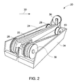
- FIG. 2 is a schematic representation of a system for continuous process for altering a dimension of a metallic glass ribbon.
- Embodiments of the present invention include methods for altering a dimension of an element made of an amorphous metallic material.
- amorphous metallic material refers to a magnetic material where a continuous matrix phase has an amorphous nature, i.e. a disordered atomic-scale structure that does not have long-range crystallographic order.
- the amorphous metallic material may also include crystalline phases within the amorphous matrix.
- the amorphous metallic material is a metallic glass ribbon that exhibits soft magnetic properties.
- the method is based on the principle of electrochemical machining (ECM). ECM uses electrical potential energy to drive chemical reactions that remove material from a workpiece (anode). Typically in ECM, an electrolytic cell is created in an electrolyte medium, with a cathode (tool) and an anode (workpiece).
- amorphous metallic materials are not easy to machine or work into desired shapes.
- Conventional machining may induce defects or stresses that degrade the magnetic properties of the material.
- the methods of fabricating these materials such as melt spinning, for example, are often relied upon to produce the articles of desired shapes, with little or no mechanical post-processing.
- melt spinning for example
- employing the ECM process includes carefully selecting an electrolyte that ensures none or very limited structural damage to the anode.
- the electrolyte is selected such that the component materials of the anode have substantially similar removal rates in the presence of the selected electrolyte solution, to avoid deleterious alteration of the anode composition and properties.
- the method enables the amorphous metallic material to retain its magnetic properties while altering the material shape and dimensions.
- the method includes providing an anode, which comprises the amorphous metallic material.
- the amorphous metallic material of the anode includes at least two primary constituents.
- the two primary constituents are capable of being oxidized during the process.
- a cathode is disposed in a spaced-apart relationship with the anode. Both the anode and cathode are in contact with an electrolyte.
- An electrical potential is applied for a period of time between the anode and the cathode via the electrolyte.
- a high-amperage, low-voltage current is employed to dissolve the two primary constituents from the anode into the electrolyte.
- the current may be a pulsed current.
- the two primary constituents in the anode are oxidized.
- the constituents that are oxidized are primarily from the surface of the anode; the oxidized constituents (metal ions) may form hydroxides that are dissolved or otherwise entrained in the electrolyte.
- the metal hydroxides in the electrolyte form undesired/unwanted sludge in the electrolyte.
- the sludge containing the hydroxides may be removed from the electrolyte by centrifugal separation. Both the electrolyte and the sludge may be recycled and regenerated. Regeneration of the electrolyte is particularly useful when employing a continuous processes. Non-limiting examples of regeneration of the electrolyte may include filtration, reverse plating, and chemical monitoring where "make-up" fresh electrolyte is used to keep electrolyte conductivity within certain process boundaries. In certain embodiments, filtration and periodic addition of fresh solution is used for regeneration of the electrolyte. Filtration may use a porous media.
- the filter may be a bag or a tube that retains and removes the precipitated hydroxides.
- the anode and the cathode may be disposed in a flowing electrolyte solution, such that the flowing electrolyte solution washes the metal ions away from the anode.
- the flowing electrolyte solution may be periodically recycled and regenerated.
- the methods of the present invention may be employed to uniformly reduce a thickness of the anode.
- uniformly means that the reduction in thickness at any given portion is within 5 percent deviation throughout the surface of the element that is undergoing reduction in thickness.
- the distance between anode and cathode is substantially the same throughout the body of the anode and cathode.
- the thickness of the anode may be reduced from about 30 microns to about 10 microns.
- a dimension of the element may be altered non-uniformly.
- the intentional non-uniform reduction in thickness may be to provide a desired shape to at least a portion of the anode.
- the distance between the anode and cathode may be varied for different portions of the anode and cathode. Because of the electrical resistance of the electrolyte, for a given electrode geometry the current density is typically the highest at the position where the distance between the anode and cathode is the smallest. As a result the corresponding area of the anode closest to the cathode may dissolve at the highest rate.
- the different distances result in different removal rates of the material from the anode, thereby resulting in different amounts of reduction in thickness at the different portions of the anode. Accordingly, different shapes, contours, angles, edges, cavities, and the like may be formed in the element by employing the present technique.
- the method commences by providing an anode comprising the amorphous metallic material.
- the amorphous metallic material comprises at least two primary constituents (block 12).
- at least one of the primary constituents includes ferromagnetic constituents.
- at least one other of the primary constituents comprises a glass-forming element.
- the ferromagnetic constituent is selected from the group consisting of iron, cobalt, and nickel.
- the glass-forming element may be one or more of boron, silicon, carbon, phosphorous, germanium, zirconium, niobium, or molybdenum.
- the amorphous metallic material may include iron and cobalt as the ferromagnetic constituent.
- the amorphous metallic material may include iron as the ferromagnetic constituent, and boron, silicon and niobium as the glass-forming element.
- the amorphous metallic material may include iron and cobalt as the ferromagnetic constituent and boron, silicon, phosphorous, carbon and molybdenum as the glass-forming constituent.
- Suitable examples of amorphous metallic materials may include commercially available products from Hitachi including: METGLAS 2605SC, METGLAS 2605S-3A, METGLAS 2705M, METGLAS 2826MB, METGLAS 2605CO, and FINEMET.
- a cathode is disposed in a spaced-apart relationship with the anode.
- the cathode material may include copper, copper-tungsten, brass, stainless steel, titanium, gold, platinum, graphite and the like.
- the distance between the cathode and anode is relatively small. Initially, the distance between the cathode and the anode may be just a few millimeters. For example, the distance between the cathode and the anode before the commencement of the process may be in a range from about 1 millimeter to about 3 millimeters.
- the space between the cathode and the anode may be kept substantially constant during the process.
- substantially constant is defined as falling within industry recognized manufacturing tolerances, and ordinary and anticipated dimensional variations in the process and may encompass variations in a range from about -5 percent to about + 5 percent.
- the anode or the cathode may be moved with respect to each other to maintain the constant distance as the dimension of the anode is altered during the process.
- the cathode may be gradually moved towards the anode as the thickness of the anode is gradually reduced during the process. The speed with which the anode or the cathode is moved may depend on the rate of removal of the material form the surface of the anode.
- the simultaneous movement of the cathode may be set at about 0.02 millimeter/second toward the anode. In one embodiment, the distance between the anode and cathode may be maintained at about 0.4 millimeters throughout the process.
- the distance between the cathode and the anode may vary during the process. For example, if the position of the cathode and the anode is fixed, the alteration in the dimension of the element may result in the increase in space between the anode and the cathode. In one example, the distance between the anode and the cathode may increase with the reduction in thickness of the anode. In one embodiment, the distance between the anode and the cathode before the commencement of the process is in a range from about 1 millimeter to about 1.5 millimeters.
- an electrolyte is provided in contact with the anode and the cathode.
- neutral salts are preferred as electrolytes for conventional ECM process.
- an aqueous-based acidic electrolyte is employed to dissolve the at least two primary constituents from the anode.
- a pH of the electrolyte is in a range from about 2 to about 6, in particular embodiments; the pH is in a range from about 2 to about 4.
- the electrolyte may be an aqueous solution of phosphoric acid.
- the electrolyte comprises about 70 percent by weight to about 90 percent by weight phosphoric acid in an aqueous solution.
- the electrolyte is selected such that the electrolyte achieves acceptable levels of anode material removal without undue damage to cathode materials.
- An electrolyte having a high amount of phosphoric acid (for example, 85 percent by weight and higher) is required to be handled safely due to the toxicity of such an electrolyte.
- the electrolyte is desirably able to maintain certain significant characteristics, such as its composition and pH value, during the machining period.
- the electrolyte has substantially similar etch rates for the primary constituents of the amorphous metallic material.
- the rate of removal of the at least two primary constituents may depend on the atomic weight and the ionic charge of the two primary constituents, the amount of current which is passed through the anode, and the time for which the current passes.
- the substantially similar etch rates for the two primary constituents facilitate alteration in the dimension of the anode while preventing formation of pin holes, or any such structural defects in the anode; in addition, the similar removal rate provides for material removal without substantially altering the composition and properties of the remaining anode material.
- the anions in the electrolyte are typically selected to avoid or minimize passive film formation on the surface of the anode during the dissolution process.
- process conditions may be manipulated to leave a passive oxide layer on the surface of the anode at the end of the process.
- the cations in the electrolyte should not deposit on the cathode surface so that the cathode shape remains unchanged.
- the electrolyte may have a forward flow, a reverse flow, or a side flow.
- Forward flow has the electrode and electrolyte moving in the same direction.
- Reverse flow has the electrode and electrolyte moving in opposite directions.
- the reverse flow can be counter current.
- Side flow has the electrolyte flowing perpendicular to the direction of electrode movement.
- the selection of the flow method may be based on the shape of the anode. Typically, forward and reverse flows are employed to drill holes or forming cavities, whereas the side flow method is often used for non-cavity shaping, such as profile formation, thickness reduction. It is desirable to have the electrolyte flow uniformly over the entire surface of the anode undergoing alteration in dimension.
- the electrolyte is pumped through the interelectrode gap so that the products of the electrolysis are carried away.
- the forced movement of the electrolyte also diminishes the effects both of electrical heating of the electrolyte (resulting from the passage of current) and formation of hydrogen gas; these two effects respectively increase and decrease the effective conductivity of the electrolyte.
- the electrolyte carries away heat generated by the process, thus maintaining a constant temperature in the region in and around the electrodes.
- the flow of the electrolyte enables removal of the debris of the electrochemical reactions from the gap between the anode and the cathode.
- an electrical potential is applied for a period of time between the anode and the cathode.
- the electrical potential drives the electrochemical reaction between the anode and the cathode as a result of which at least two primary constituents of the anode are oxidized at the anode and dissolve in the electrolyte solution.
- the dissolution of the two primary constituents in the electrolyte results in alteration of the dimension of the anode.
- the dissolution of the two primary constituents in the electrolyte results in reduction in thickness of the anode.
- the potential applied may be in a range from about 2 volts to about 5 volts.
- the period of time for applying the potential may depend upon the amount of alteration in the dimension desirable at the anode.
- the period of time may be in a range from about 2 minutes to about 60 minutes. In one embodiment, the period of time may be about 30 minutes.
- the value of the applied potential may depend on the chemical composition of the anode. For example, for a chemical composition in weight percent of Fe 62.4 percent, Co 15.6 percent, Mo 1 percent, P 10 percent, B 3 percent, C 7 percent, and Si 1 percent, the applied potential is about 4V.
- the electrical current for the process may be in a range from about 50 mA to about 10 A. Generally, under processing conditions where current is attributable mostly to the dissolution of metal, a higher current density results in a faster material removal rate.
- the current may be a DC current.
- the current may be a pulsed current. In one example, periodic application and removal of potential may provide a short pulse of anode dissolution. The short pulse of anode dissolution may be followed by a short interval where no reaction is occurring prior to the next pulse of anode dissolution.
- FIG. 2 illustrates an arrangement 20 for a continuous process for altering a dimension of a metallic glass ribbon.
- ribbon means a slender body of substantially rectangular cross section whose transverse dimensions are much smaller than the length.
- the metallic glass ribbon is typically fabricated by a melt-spinning process.
- the metallic glass ribbon 22 runs along the electrolyte bath 24 over the spools 26 and 28.
- the electrolyte has a forward flow as illustrated by the reference numeral 30.
- the metallic glass ribbon 22 may run in the electrolyte bath 24 at a constant speed.
- the speed of the metallic glass ribbon 22 is such that a given portion of the metallic glass ribbon 22 is placed in the electrolyte bath 24 for a determined period of time to enable a required amount of dissolution of the material from the anode in the electrolyte bath 24.
- a cathode (not shown) is disposed at the bottom 32 of the electrolyte bath 24.
- the cathode (not shown) may run along the length of the electrolyte bath 24 and be in the form of a strip that may cover at least a portion of the bottom across the width of the electrolyte bath 24.
- the metallic glass ribbon 22 may be rinsed in a de-ionized (DI) water bath 34.
- DI water bath 34 is disposed adjacent to the electrolyte bath 24.
- a spool 36 is employed to transfer the metallic glass ribbon 32 from the electrolyte bath 24 to the DI water bath 34.
- the metallic glass ribbon runs on the spools 38 and 40.
- the DI water may be periodically replaced or replenished.
- a filter may be in operative association with the electrolyte bath 24, such that the electrolyte bath 24 may be periodically filtered to remove at least a part of the sludge.
- the filtered electrolyte 24 may be pumped back in the electrolyte bath 24 by employing a pump.
- the electrolyte may also be subjected to precipitation prior to being filtered. The precipitation may be carried out to reduce the amount of metal sludge from the electrolyte by precipitating the metal hydroxides.
- An electrolyte reservoir may be coupled to the system to pump in fresh (non-contaminated) electrolyte periodically.
- the DI water bath 34 may be in a straight-line configuration with the electrolyte bath 24.
- the amorphous metallic material element processed in accordance with the above method is employed in an electrical device such as a core used in a transformer, inductor or motor.
- an electrical device such as a core used in a transformer, inductor or motor.
- toroidal cores are first wound in their final configuration and then annealed, often with a magnetic field applied. This anneal serves to relieve stresses in the metallic glass ribbons resulting both from the rapid quench during melt-spinning of the ribbons and from bending stresses in the metallic glass ribbons due to the curvature of the ribbon in the toroidal core.
- amorphous metallic material element of the present technique may include power transformers, common mode chokes, magnetic amplifiers, high precision current transformers for electronic energy meters, ISDN-transformer, sensors, such as fluxgate magnetometer, stress sensor, security sensor.
- the effects of four different electrolyte compositions were studied for dissolution of a metallic glass ribbon.
- the nominal chemical composition of the metallic glass ribbon in weight percent was Fe 62.4 percent, Co 15.6 percent, Mo 1 percent, P 10 percent, B 3 percent, C 7 percent, and Si 1 percent.
- the metallic glass ribbon was fabricated using melt spinning equipment. The thickness of the ribbon was about 23 microns.
- the ribbon was cut into four pieces and, after being rinsed with deionized water, each piece was separately immersed in four different types of electrolyte baths.
- the cathode was made of oxygen free copper. The cathode was approximately 5 times larger in area than the area of ribbon exposed in the electrolyte solution.
- the first electrolyte bath was a 10 percent aqueous solution of sodium nitrate.
- the second electrolyte bath was 1 M sulfuric acid.
- the third electrolyte bath was a mixture of hydrofluoric, nitric, and hydrochloric acids.
- the fourth electrolyte bath was an aqueous solution of 85 weight percent phosphoric acid.
- the ribbons were immersed for a period of 10 minutes. An electric potential of 4 Volts was applied across the electrolyte baths.
- the ribbons in the first, second and third electrolyte baths were oxidized on the surface or throughout the entire cross-section. This oxidation was undesirable for usage as magnetic cores.
- the ribbon in the fourth electrolyte bath using aqueous solution of phophoric acid did not result in any surface oxide, and provided a good surface fmish (by substantially avoiding formation of pin holes) and a uniformly reduced thickness of about 10 microns.
Landscapes
- Chemical & Material Sciences (AREA)
- Engineering & Computer Science (AREA)
- Mechanical Engineering (AREA)
- Metallurgy (AREA)
- Materials Engineering (AREA)
- Organic Chemistry (AREA)
- Electrochemistry (AREA)
- Chemical Kinetics & Catalysis (AREA)
- Physics & Mathematics (AREA)
- Thermal Sciences (AREA)
- Manufacturing Cores, Coils, And Magnets (AREA)
- Soft Magnetic Materials (AREA)
- Electrical Discharge Machining, Electrochemical Machining, And Combined Machining (AREA)
- Electroplating Methods And Accessories (AREA)
Abstract
Description
- The invention relates generally to amorphous metallic materials, and particularly to methods for altering a dimension of amorphous metallic materials.
- Generally, amorphous metallic materials exhibit high permeability and ease of magnetization. Typically, cores for electric devices such as transformers, inductors or motors are formed by amorphous metallic materials that are arranged to form a stack or a coil. These stacks or coils are then cut into desired shapes to be employed in the core.
- Conventional amorphous metallic materials are formed by rapid solidification of an alloy, that is, by cooling the alloy to a temperature below the glass transition temperature before appreciable nucleation and crystallization has occurred. Melt spinning is typically employed to fabricate metal ribbons or tapes that have some ductility.
- Amorphous metallic materials generally are prepared with small dimensions due to the need to extract heat at a sufficient rate to suppress crystallization. However, the currently employed processes, such as melt spinning, often are subject to process limitations that prevent producing articles with desired dimensions. For example, amorphous metallic material ribbons produced by employing melt spinning have thickness values higher than desired for certain high frequency applications. Metallic glass ribbons with reduced thicknesses are useful for achieving lower core loss properties due to a reduction in the eddy current losses which are proportional to the metallic glass ribbon cross-sectional area.
- Therefore, there is a need for providing a method for altering a dimension of an element made of amorphous metallic materials.
- One embodiment of the present invention provides a method for altering a dimension of an element made of an amorphous metallic material. The method includes providing an anode comprising the amorphous metallic material, wherein the amorphous metallic material comprises at least two primary constituents, providing a cathode disposed in a spaced-apart relationship with the anode, providing an electrolyte in contact with the anode and the cathode, and applying an electrical potential between the anode and the cathode.
- Another embodiment of the present invention provides a method for altering a dimension of an element made of an amorphous metallic material. The method includes providing an anode feedstock comprising the amorphous metallic material, wherein the amorphous metallic material comprises at least two primary constituents, providing a cathode; providing an electrolyte in contact with a portion of the anode feedstock and the cathode, wherein the portion of the anode feedstock and the cathode are disposed in a spaced-apart relationship, applying an electrical potential between cathode and the portion of the anode feedstock that is disposed in the electrolyte, and continuously feeding the anode feedstock into the electrolyte.
- Yet another embodiment of the present invention provides a method for uniformly reducing a thickness of a metallic glass ribbon. The method includes providing the metallic glass ribbon as an anode feedstock, disposing the metallic glass ribbon in an electrolyte bath, wherein the electrolyte bath comprises phosphoric acid; providing a cathode in a spaced-apart relationship with the metallic glass ribbon, and applying an electrical potential between the metallic glass ribbon and the cathode to remove at least a part of the two primary constituents from the metallic glass ribbon.
- These and other features, aspects, and advantages of the present invention will become better understood when the following detailed description is read with reference to the accompanying drawings in which like characters represent like parts throughout the drawings, wherein:
-
FIG. 1 is a flow chart illustrating an example of various steps involved in the method for altering a dimension of an element made of an amorphous metallic material; and -
FIG. 2 is a schematic representation of a system for continuous process for altering a dimension of a metallic glass ribbon. - Embodiments of the present invention include methods for altering a dimension of an element made of an amorphous metallic material. As used herein, the term "amorphous metallic material" refers to a magnetic material where a continuous matrix phase has an amorphous nature, i.e. a disordered atomic-scale structure that does not have long-range crystallographic order. The amorphous metallic material may also include crystalline phases within the amorphous matrix. In certain embodiments, the amorphous metallic material is a metallic glass ribbon that exhibits soft magnetic properties. The method is based on the principle of electrochemical machining (ECM). ECM uses electrical potential energy to drive chemical reactions that remove material from a workpiece (anode). Typically in ECM, an electrolytic cell is created in an electrolyte medium, with a cathode (tool) and an anode (workpiece).
- Generally, amorphous metallic materials are not easy to machine or work into desired shapes. Conventional machining may induce defects or stresses that degrade the magnetic properties of the material. For this reason, the methods of fabricating these materials, such as melt spinning, for example, are often relied upon to produce the articles of desired shapes, with little or no mechanical post-processing. However, due to process limitations, it may not be often feasible to produce directly the element with desired shape and dimensions.
- Conventionally, the ECM process is employed to form intricate parts from otherwise strong, generally crystalline, metals. However, the application of ECM to amorphous metallic materials requires special considerations to achieve proper results. In embodiments of the present invention, employing the ECM process includes carefully selecting an electrolyte that ensures none or very limited structural damage to the anode. The electrolyte is selected such that the component materials of the anode have substantially similar removal rates in the presence of the selected electrolyte solution, to avoid deleterious alteration of the anode composition and properties. In certain embodiments, the method enables the amorphous metallic material to retain its magnetic properties while altering the material shape and dimensions.
- In certain embodiments, the method includes providing an anode, which comprises the amorphous metallic material. The amorphous metallic material of the anode includes at least two primary constituents. The two primary constituents are capable of being oxidized during the process. A cathode is disposed in a spaced-apart relationship with the anode. Both the anode and cathode are in contact with an electrolyte. An electrical potential is applied for a period of time between the anode and the cathode via the electrolyte. In certain embodiments, a high-amperage, low-voltage current is employed to dissolve the two primary constituents from the anode into the electrolyte. In one embodiment, the current may be a pulsed current. Upon application of the voltage, at least a portion of the two primary constituents in the anode are oxidized. The constituents that are oxidized are primarily from the surface of the anode; the oxidized constituents (metal ions) may form hydroxides that are dissolved or otherwise entrained in the electrolyte.
- The metal hydroxides in the electrolyte form undesired/unwanted sludge in the electrolyte. In certain embodiments, the sludge containing the hydroxides may be removed from the electrolyte by centrifugal separation. Both the electrolyte and the sludge may be recycled and regenerated. Regeneration of the electrolyte is particularly useful when employing a continuous processes. Non-limiting examples of regeneration of the electrolyte may include filtration, reverse plating, and chemical monitoring where "make-up" fresh electrolyte is used to keep electrolyte conductivity within certain process boundaries. In certain embodiments, filtration and periodic addition of fresh solution is used for regeneration of the electrolyte. Filtration may use a porous media. In one example, the filter may be a bag or a tube that retains and removes the precipitated hydroxides. In one embodiment, the anode and the cathode may be disposed in a flowing electrolyte solution, such that the flowing electrolyte solution washes the metal ions away from the anode. The flowing electrolyte solution may be periodically recycled and regenerated.
- In some embodiments, the methods of the present invention may be employed to uniformly reduce a thickness of the anode. As used herein, the term "uniformly" means that the reduction in thickness at any given portion is within 5 percent deviation throughout the surface of the element that is undergoing reduction in thickness. In these embodiments, the distance between anode and cathode is substantially the same throughout the body of the anode and cathode. In one example, the thickness of the anode may be reduced from about 30 microns to about 10 microns.
- In other embodiments, a dimension of the element may be altered non-uniformly. For example, the intentional non-uniform reduction in thickness may be to provide a desired shape to at least a portion of the anode. In these embodiments, the distance between the anode and cathode may be varied for different portions of the anode and cathode. Because of the electrical resistance of the electrolyte, for a given electrode geometry the current density is typically the highest at the position where the distance between the anode and cathode is the smallest. As a result the corresponding area of the anode closest to the cathode may dissolve at the highest rate. That is, the different distances result in different removal rates of the material from the anode, thereby resulting in different amounts of reduction in thickness at the different portions of the anode. Accordingly, different shapes, contours, angles, edges, cavities, and the like may be formed in the element by employing the present technique.
- As illustrated in the flow chart of
FIG. 1 , the method commences by providing an anode comprising the amorphous metallic material. The amorphous metallic material comprises at least two primary constituents (block 12). In one embodiment, at least one of the primary constituents includes ferromagnetic constituents. In this embodiment, at least one other of the primary constituents comprises a glass-forming element. The ferromagnetic constituent is selected from the group consisting of iron, cobalt, and nickel. The glass-forming element may be one or more of boron, silicon, carbon, phosphorous, germanium, zirconium, niobium, or molybdenum. In one example, the amorphous metallic material may include iron and cobalt as the ferromagnetic constituent. In another example, the amorphous metallic material may include iron as the ferromagnetic constituent, and boron, silicon and niobium as the glass-forming element. In another example, the amorphous metallic material may include iron and cobalt as the ferromagnetic constituent and boron, silicon, phosphorous, carbon and molybdenum as the glass-forming constituent. Suitable examples of amorphous metallic materials may include commercially available products from Hitachi including: METGLAS 2605SC, METGLAS 2605S-3A, METGLAS 2705M, METGLAS 2826MB, METGLAS 2605CO, and FINEMET. - At
block 14, a cathode is disposed in a spaced-apart relationship with the anode. Non-limiting examples of the cathode material may include copper, copper-tungsten, brass, stainless steel, titanium, gold, platinum, graphite and the like. The distance between the cathode and anode is relatively small. Initially, the distance between the cathode and the anode may be just a few millimeters. For example, the distance between the cathode and the anode before the commencement of the process may be in a range from about 1 millimeter to about 3 millimeters. - In one embodiment, the space between the cathode and the anode may be kept substantially constant during the process. As used herein, the term "substantially constant" is defined as falling within industry recognized manufacturing tolerances, and ordinary and anticipated dimensional variations in the process and may encompass variations in a range from about -5 percent to about + 5 percent. In this embodiment, the anode or the cathode may be moved with respect to each other to maintain the constant distance as the dimension of the anode is altered during the process. For example, the cathode may be gradually moved towards the anode as the thickness of the anode is gradually reduced during the process. The speed with which the anode or the cathode is moved may depend on the rate of removal of the material form the surface of the anode. In one example, as the machining proceeds, the simultaneous movement of the cathode may be set at about 0.02 millimeter/second toward the anode. In one embodiment, the distance between the anode and cathode may be maintained at about 0.4 millimeters throughout the process.
- In another embodiment, the distance between the cathode and the anode may vary during the process. For example, if the position of the cathode and the anode is fixed, the alteration in the dimension of the element may result in the increase in space between the anode and the cathode. In one example, the distance between the anode and the cathode may increase with the reduction in thickness of the anode. In one embodiment, the distance between the anode and the cathode before the commencement of the process is in a range from about 1 millimeter to about 1.5 millimeters.
- At
block 16, an electrolyte is provided in contact with the anode and the cathode. Typically, neutral salts are preferred as electrolytes for conventional ECM process. However, in embodiments of the present invention, an aqueous-based acidic electrolyte is employed to dissolve the at least two primary constituents from the anode. In certain embodiments, a pH of the electrolyte is in a range from about 2 to about 6, in particular embodiments; the pH is in a range from about 2 to about 4. In one embodiment, the electrolyte may be an aqueous solution of phosphoric acid. In one example, the electrolyte comprises about 70 percent by weight to about 90 percent by weight phosphoric acid in an aqueous solution. - The electrolyte is selected such that the electrolyte achieves acceptable levels of anode material removal without undue damage to cathode materials. An electrolyte having a high amount of phosphoric acid (for example, 85 percent by weight and higher) is required to be handled safely due to the toxicity of such an electrolyte. Also, the electrolyte is desirably able to maintain certain significant characteristics, such as its composition and pH value, during the machining period. The electrolyte has substantially similar etch rates for the primary constituents of the amorphous metallic material. In addition to the electrolyte composition, the rate of removal of the at least two primary constituents may depend on the atomic weight and the ionic charge of the two primary constituents, the amount of current which is passed through the anode, and the time for which the current passes. The substantially similar etch rates for the two primary constituents facilitate alteration in the dimension of the anode while preventing formation of pin holes, or any such structural defects in the anode; in addition, the similar removal rate provides for material removal without substantially altering the composition and properties of the remaining anode material.
- The anions in the electrolyte are typically selected to avoid or minimize passive film formation on the surface of the anode during the dissolution process. However, it should be noted that obtaining a product having a very thin oxide layer may be desirable for certain applications. In such cases, process conditions may be manipulated to leave a passive oxide layer on the surface of the anode at the end of the process. In addition, the cations in the electrolyte should not deposit on the cathode surface so that the cathode shape remains unchanged.
- In one embodiment, the electrolyte may have a forward flow, a reverse flow, or a side flow. Forward flow has the electrode and electrolyte moving in the same direction. Reverse flow has the electrode and electrolyte moving in opposite directions. The reverse flow can be counter current. Side flow has the electrolyte flowing perpendicular to the direction of electrode movement. The selection of the flow method may be based on the shape of the anode. Typically, forward and reverse flows are employed to drill holes or forming cavities, whereas the side flow method is often used for non-cavity shaping, such as profile formation, thickness reduction. It is desirable to have the electrolyte flow uniformly over the entire surface of the anode undergoing alteration in dimension.
- In certain embodiments, the electrolyte is pumped through the interelectrode gap so that the products of the electrolysis are carried away. The forced movement of the electrolyte also diminishes the effects both of electrical heating of the electrolyte (resulting from the passage of current) and formation of hydrogen gas; these two effects respectively increase and decrease the effective conductivity of the electrolyte. The electrolyte carries away heat generated by the process, thus maintaining a constant temperature in the region in and around the electrodes. Moreover, the flow of the electrolyte enables removal of the debris of the electrochemical reactions from the gap between the anode and the cathode.
- At
block 18, an electrical potential is applied for a period of time between the anode and the cathode. The electrical potential drives the electrochemical reaction between the anode and the cathode as a result of which at least two primary constituents of the anode are oxidized at the anode and dissolve in the electrolyte solution. The dissolution of the two primary constituents in the electrolyte results in alteration of the dimension of the anode. For example, the dissolution of the two primary constituents in the electrolyte results in reduction in thickness of the anode. In one embodiment, the potential applied may be in a range from about 2 volts to about 5 volts. The period of time for applying the potential may depend upon the amount of alteration in the dimension desirable at the anode. The period of time may be in a range from about 2 minutes to about 60 minutes. In one embodiment, the period of time may be about 30 minutes. The value of the applied potential may depend on the chemical composition of the anode. For example, for a chemical composition in weight percent of Fe 62.4 percent, Co 15.6 percent, Mo 1 percent, P 10 percent, B 3 percent, C 7 percent, and Si 1 percent, the applied potential is about 4V. - The electrical current for the process may be in a range from about 50 mA to about 10 A. Generally, under processing conditions where current is attributable mostly to the dissolution of metal, a higher current density results in a faster material removal rate. The current may be a DC current. The current may be a pulsed current. In one example, periodic application and removal of potential may provide a short pulse of anode dissolution. The short pulse of anode dissolution may be followed by a short interval where no reaction is occurring prior to the next pulse of anode dissolution.
-
FIG. 2 illustrates anarrangement 20 for a continuous process for altering a dimension of a metallic glass ribbon. As used herein, the term "ribbon" means a slender body of substantially rectangular cross section whose transverse dimensions are much smaller than the length. The metallic glass ribbon is typically fabricated by a melt-spinning process. In the illustrated embodiment, themetallic glass ribbon 22 runs along theelectrolyte bath 24 over thespools reference numeral 30. - The
metallic glass ribbon 22 may run in theelectrolyte bath 24 at a constant speed. The speed of themetallic glass ribbon 22 is such that a given portion of themetallic glass ribbon 22 is placed in theelectrolyte bath 24 for a determined period of time to enable a required amount of dissolution of the material from the anode in theelectrolyte bath 24. - A cathode (not shown) is disposed at the bottom 32 of the
electrolyte bath 24. The cathode (not shown) may run along the length of theelectrolyte bath 24 and be in the form of a strip that may cover at least a portion of the bottom across the width of theelectrolyte bath 24. - Optionally, after passing through the
electrolyte bath 24, themetallic glass ribbon 22 may be rinsed in a de-ionized (DI)water bath 34. In the illustrated embodiment, theDI water bath 34 is disposed adjacent to theelectrolyte bath 24. Aspool 36 is employed to transfer the metallic glass ribbon 32 from theelectrolyte bath 24 to theDI water bath 34. In theDI water bath 34, the metallic glass ribbon runs on thespools - In addition, a filter may be in operative association with the
electrolyte bath 24, such that theelectrolyte bath 24 may be periodically filtered to remove at least a part of the sludge. The filteredelectrolyte 24 may be pumped back in theelectrolyte bath 24 by employing a pump. The electrolyte may also be subjected to precipitation prior to being filtered. The precipitation may be carried out to reduce the amount of metal sludge from the electrolyte by precipitating the metal hydroxides. An electrolyte reservoir may be coupled to the system to pump in fresh (non-contaminated) electrolyte periodically. - Although not illustrated, in a simpler arrangement requiring more space, the
DI water bath 34 may be in a straight-line configuration with theelectrolyte bath 24. - In certain embodiments, the amorphous metallic material element processed in accordance with the above method is employed in an electrical device such as a core used in a transformer, inductor or motor. To obtain optimum magnetic properties in magnetic cores made from metallic glass ribbons, toroidal cores are first wound in their final configuration and then annealed, often with a magnetic field applied. This anneal serves to relieve stresses in the metallic glass ribbons resulting both from the rapid quench during melt-spinning of the ribbons and from bending stresses in the metallic glass ribbons due to the curvature of the ribbon in the toroidal core.
- Other applications for the amorphous metallic material element of the present technique may include power transformers, common mode chokes, magnetic amplifiers, high precision current transformers for electronic energy meters, ISDN-transformer, sensors, such as fluxgate magnetometer, stress sensor, security sensor.
- The effects of four different electrolyte compositions were studied for dissolution of a metallic glass ribbon. The nominal chemical composition of the metallic glass ribbon in weight percent was Fe 62.4 percent, Co 15.6 percent, Mo 1 percent, P 10 percent, B 3 percent, C 7 percent, and Si 1 percent. The metallic glass ribbon was fabricated using melt spinning equipment. The thickness of the ribbon was about 23 microns.
- The ribbon was cut into four pieces and, after being rinsed with deionized water, each piece was separately immersed in four different types of electrolyte baths. The cathode was made of oxygen free copper. The cathode was approximately 5 times larger in area than the area of ribbon exposed in the electrolyte solution. The first electrolyte bath was a 10 percent aqueous solution of sodium nitrate. The second electrolyte bath was 1 M sulfuric acid. The third electrolyte bath was a mixture of hydrofluoric, nitric, and hydrochloric acids. The fourth electrolyte bath was an aqueous solution of 85 weight percent phosphoric acid. The ribbons were immersed for a period of 10 minutes. An electric potential of 4 Volts was applied across the electrolyte baths.
- The ribbons in the first, second and third electrolyte baths were oxidized on the surface or throughout the entire cross-section. This oxidation was undesirable for usage as magnetic cores. The ribbon in the fourth electrolyte bath using aqueous solution of phophoric acid did not result in any surface oxide, and provided a good surface fmish (by substantially avoiding formation of pin holes) and a uniformly reduced thickness of about 10 microns.
- Commercially available metallic glass ribbons from Hitachi including METGLAS 2605SC, METGLAS 2605S-3A, METGLAS 2705M, METGLAS 2826MB, and METGLAS 2605CO were subjected to 85 percent phosphoric acid solution. Each ribbon sample was subjected to 4 volts applied potential for 10 minutes immersed in 85 percent phosphoric acid. All the samples were successfully etched using the method of the present application. The samples did not display any adverse effects with respect to the magnetic properties.
- For completeness, various aspects of the invention are now set out in the following numbered clauses:
- 1. A method for altering a dimension of an element made of an amorphous metallic material, comprising:
- providing an anode comprising the amorphous metallic material, wherein the amorphous metallic material comprises at least two primary constituents;
- providing a cathode disposed in a spaced-apart relationship with the anode;
- providing an electrolyte in contact with the anode and the cathode; and
- applying an electrical potential between the anode and the cathode.
- 2. The method of clause 1, wherein at least one of the primary consitituents comprises a ferromagnetic constituent.
- 3. The method of clause 2, wherein at least one other of the primary constituents comprises a glass-forming element.
- 4. The method of clause 2, wherein the ferromagnetic constituent is selected from the group consisting of iron, cobalt, and nickel.
- 5. The method of clause 2, wherein the ferromagnetic constituent comprises iron and cobalt.
- 6.The method of clause 1, wherein at least one of the primary constituents comprises a glass-forming element.
- 7. The method of clause 6, wherein the glass-forming element comprises boron, silicon, carbon, phosphorous, germanium, zirconium, niobium, or molybdenum.
- 8. The method of clause 1, wherein the cathode comprises copper.
- 9. The method of clause 1, wherein the electrolyte comprises an acid.
- 10. The method of clause 9, wherein the a pH of the electrolyte is in a range from about 2 to about 4.
- 11. The method of clause 9, wherein the electrolyte comprises an aqueous solution.
- 12. The method of clause 9, wherein the electrolyte comprises phosphoric acid.
- 13. The method of clause 9, wherein the electrolyte comprises about 70 percent by weight to about 90 percent by weight phosphoric acid in an aqueous solution.
- 14. The method of clause 1, wherein the potential is in a range from about 2 volts to about 5 volts.
- 15. The method of clause 1, wherein the electrolyte has substantially similar etch rates for the two primary consituents of the amorphous metallic material.
- 16. The method of clause 1, further comprising maintaining a substantially constant distance between the anode and cathode.
- 17. The method of clause 1, wherein the anode comprises a metallic glass ribbon.
- 18. A method for altering a dimension of an element made of an amorphous metallic material, comprising:
- providing an anode feedstock comprising the amorphous metallic material, wherein
- the amorphous metallic material comprises at least two primary constituents;
- providing a cathode;
- providing an electrolyte in contact with a portion of the anode feedstock and the cathode, wherein the portion of the anode feedstock and the cathode are disposed in a spaced-apart relationship;
- applying an electrical potential between cathode and the portion of the anode feedstock that is disposed in the electrolyte; and
- continuously feeding the anode feedstock into the electrolyte.
- 19. The method of
clause 18, wherein the anode feedstock is provided on a roll. - 20. The method of
clause 18, further comprising, rinsing at least a portion of the thinned anode feedstock with de-ionized water. - 21. The method of
clause 18, wherein the anode feedstock comprises a metallic glass ribbon. - 22. A method for uniformly reducing a thickness of a metallic glass ribbon, the method comprising:
- providing the metallic glass ribbon as an anode feedstock;
- disposing the metallic glass ribbon in an electrolyte bath, wherein the electrolyte bath comprises phosphoric acid;
- providing a cathode in a spaced-apart relationship with the metallic glass ribbon; and applying an electrical potential between the metallic glass ribbon and the cathode to remove at least a part of the two primary constituents from the metallic glass ribbon.
Claims (15)
- A method for altering a dimension of an element made of an amorphous metallic material, comprising:providing an anode comprising the amorphous metallic material, wherein the amorphous metallic material comprises at least two primary constituents;providing a cathode disposed in a spaced-apart relationship with the anode;providing an electrolyte in contact with the anode and the cathode; andapplying an electrical potential between the anode and the cathode.
- The method of claim 1, wherein at least one of the primary consitituents comprises a ferromagnetic constituent.
- The method of claim 2, wherein at least one other of the primary constituents comprises a glass-forming element.
- The method of claim 2, wherein the ferromagnetic constituent is selected from the group consisting of iron, cobalt, nickel and combinations thereof
- The method of any one of claims 2 to 4, wherein the ferromagnetic constituent comprises iron and cobalt.
- The method of any preceding claim, wherein at least one of the primary constituents comprises a glass-forming element.
- The method of claim 6, wherein the glass-forming element comprises boron, silicon, carbon, phosphorous, germanium, zirconium, niobium, or molybdenum.
- The method of any preceding claim, wherein the cathode comprises copper.
- The method of any preceding claim, wherein the electrolyte comprises an acid.
- The method of claim 9, wherein the pH of the electrolyte is in a range from about 2 to about 4.
- The method of claim 9 or claim 10, wherein the electrolyte comprises about 70 percent by weight to about 90 percent by weight phosphoric acid in an aqueous solution.
- The method of any preceding claim, wherein the anode comprises a metallic glass ribbon.
- A method for altering a dimension of an element made of an amorphous metallic material, comprising:providing an anode feedstock comprising the amorphous metallic material, whereinthe amorphous metallic material comprises at least two primary constituents;providing a cathode;providing an electrolyte in contact with a portion of the anode feedstock and the cathode, wherein the portion of the anode feedstock and the cathode are disposed in a spaced-apart relationship;applying an electrical potential between cathode and the portion of the anode feedstock that is disposed in the electrolyte; andcontinuously feeding the anode feedstock into the electrolyte.
- The method of claim 13, wherein the anode feedstock comprises a metallic glass ribbon.
- A method for uniformly reducing a thickness of a metallic glass ribbon, the method comprising:providing the metallic glass ribbon as an anode feedstock;disposing the metallic glass ribbon in an electrolyte bath, wherein the electrolyte bath comprises phosphoric acid;providing a cathode in a spaced-apart relationship with the metallic glass ribbon; andapplying an electrical potential between the metallic glass ribbon and the cathode to remove at least a part of the two primary constituents from the metallic glass ribbon.
Applications Claiming Priority (1)
| Application Number | Priority Date | Filing Date | Title |
|---|---|---|---|
| US12/570,818 US20110073486A1 (en) | 2009-09-30 | 2009-09-30 | Amorphous metallic material elements and methods for processing same |
Publications (2)
| Publication Number | Publication Date |
|---|---|
| EP2305410A2 true EP2305410A2 (en) | 2011-04-06 |
| EP2305410A3 EP2305410A3 (en) | 2013-01-09 |
Family
ID=42735436
Family Applications (1)
| Application Number | Title | Priority Date | Filing Date |
|---|---|---|---|
| EP10171204A Withdrawn EP2305410A3 (en) | 2009-09-30 | 2010-07-29 | Amorphous metallic material elements and methods for processing same |
Country Status (4)
| Country | Link |
|---|---|
| US (1) | US20110073486A1 (en) |
| EP (1) | EP2305410A3 (en) |
| JP (1) | JP2011074486A (en) |
| CA (1) | CA2711163A1 (en) |
Families Citing this family (1)
| Publication number | Priority date | Publication date | Assignee | Title |
|---|---|---|---|---|
| CN103240473B (en) | 2012-02-07 | 2015-08-19 | 通用电气公司 | Electrode and manufacture method thereof |
Family Cites Families (9)
| Publication number | Priority date | Publication date | Assignee | Title |
|---|---|---|---|---|
| JPS5934780B2 (en) * | 1977-12-16 | 1984-08-24 | 松下電器産業株式会社 | Heat treatment method for amorphous magnetic alloy thin plate |
| US4776934A (en) * | 1987-11-23 | 1988-10-11 | General Motors Corporation | Electrolytic machining electrolyte |
| CA2126136C (en) * | 1994-06-17 | 2007-06-05 | Steven J. Thorpe | Amorphous metal/metallic glass electrodes for electrochemical processes |
| US5715133A (en) * | 1995-06-21 | 1998-02-03 | Philips Electronics North America Corporation | Method of producing aluminum foil for electrolytic capacitors and product thereof |
| US7323071B1 (en) * | 2000-11-09 | 2008-01-29 | Battelle Energy Alliance, Llc | Method for forming a hardened surface on a substrate |
| KR100559933B1 (en) * | 2002-11-29 | 2006-03-13 | 엘에스전선 주식회사 | Electropolishing method of low light copper foil and electropolishing apparatus and copper foil |
| US7510641B2 (en) * | 2003-07-21 | 2009-03-31 | Los Alamos National Security, Llc | High current density electropolishing in the preparation of highly smooth substrate tapes for coated conductors |
| KR100760339B1 (en) * | 2006-05-19 | 2007-10-04 | 한국과학기술연구원 | Nano sized porous metal glass and its manufacturing method |
| JP2008208394A (en) * | 2007-02-23 | 2008-09-11 | Seiko Epson Corp | Amorphous alloy processing method and magnetic core material |
-
2009
- 2009-09-30 US US12/570,818 patent/US20110073486A1/en not_active Abandoned
-
2010
- 2010-07-15 CA CA2711163A patent/CA2711163A1/en not_active Abandoned
- 2010-07-28 JP JP2010168732A patent/JP2011074486A/en not_active Withdrawn
- 2010-07-29 EP EP10171204A patent/EP2305410A3/en not_active Withdrawn
Non-Patent Citations (1)
| Title |
|---|
| None |
Also Published As
| Publication number | Publication date |
|---|---|
| US20110073486A1 (en) | 2011-03-31 |
| EP2305410A3 (en) | 2013-01-09 |
| JP2011074486A (en) | 2011-04-14 |
| CA2711163A1 (en) | 2011-03-30 |
Similar Documents
| Publication | Publication Date | Title |
|---|---|---|
| CN111057970B (en) | Preparation method of amorphous nanocrystalline alloy with high magnetic permeability | |
| JP6263512B2 (en) | Wide iron-based amorphous alloys are precursors of nanocrystalline alloys | |
| KR101147571B1 (en) | Iron-based soft magnetic alloy, thin ribbon of amorphous alloy, and magnetic part | |
| EP2261385B1 (en) | Thin strip of amorphous alloy, nanocrystal soft magnetic alloy, and magnetic core | |
| US9496477B2 (en) | Method for producing substrates for superconducting layers | |
| WO1993023583A1 (en) | Amorphous alloy and production thereof | |
| DE102011001784A1 (en) | Preparing a spring e.g. lift spring and/or mainspring for a mechanical clockwork, comprises melting an alloy, forming an amorphous tape from the melted alloy by a rapid solidification method, and processing a surface of the amorphous tape | |
| KR20220079518A (en) | Iron-based amorphous alloy containing sub-nano-scale regular clusters, manufacturing method, and nanocrystalline alloy derivatives thereof | |
| WO2016180359A1 (en) | Strong-permanent-magnetic nano-porous fe-pt alloy and method for preparing same | |
| JP5445891B2 (en) | Soft magnetic ribbon, magnetic core, and magnetic parts | |
| CN104619875A (en) | Ultrafine crystal alloy ribbon, fine crystal soft magnetic alloy ribbon, and magnetic parts using same | |
| CN105845307A (en) | Iron-based amorphous-state magnetically soft alloy formed by medium alloy steel components, and application of iron-based amorphous-state magnetically soft alloy | |
| KR101868013B1 (en) | Ferromagnetic amorphous alloy ribbon and fabrication thereof | |
| Dan et al. | Mechanism of active dissolution of nanocrystalline FeSiBPCu soft magnetic alloys | |
| EP2305410A2 (en) | Amorphous metallic material elements and methods for processing same | |
| US20240352567A1 (en) | Method for manufacturing fe-si-b-based thick plate rapidly solidified alloy ribbon | |
| CN115602403B (en) | Fe-based medium-high frequency amorphous nanocrystalline strip and preparation method thereof | |
| JP5445924B2 (en) | Soft magnetic ribbon, magnetic core, magnetic component, and method of manufacturing soft magnetic ribbon | |
| Inman et al. | Electropolishing and throughmask electroetching of Nitinol stents and other materials in an aqueous electrolyte | |
| Herrault et al. | Electroplating-based approaches for volumetric nanomanufacturing | |
| Dan et al. | Electrochemical Behavior of Annealed Soft-Magnetic Fe–Si–B–P–Cu Alloy | |
| Sharma et al. | Electrodeposition of ferromagnetic nanostructures | |
| JP2008208394A (en) | Amorphous alloy processing method and magnetic core material | |
| Leese | Electrochemical machining-new machining targets and adaptations with suitability for micromanufacturing | |
| JP2009088206A (en) | Method for manufacturing rare earth magnet |
Legal Events
| Date | Code | Title | Description |
|---|---|---|---|
| PUAI | Public reference made under article 153(3) epc to a published international application that has entered the european phase |
Free format text: ORIGINAL CODE: 0009012 |
|
| AK | Designated contracting states |
Kind code of ref document: A2 Designated state(s): AL AT BE BG CH CY CZ DE DK EE ES FI FR GB GR HR HU IE IS IT LI LT LU LV MC MK MT NL NO PL PT RO SE SI SK SM TR |
|
| AX | Request for extension of the european patent |
Extension state: BA ME RS |
|
| PUAL | Search report despatched |
Free format text: ORIGINAL CODE: 0009013 |
|
| AK | Designated contracting states |
Kind code of ref document: A3 Designated state(s): AL AT BE BG CH CY CZ DE DK EE ES FI FR GB GR HR HU IE IS IT LI LT LU LV MC MK MT NL NO PL PT RO SE SI SK SM TR |
|
| AX | Request for extension of the european patent |
Extension state: BA ME RS |
|
| RIC1 | Information provided on ipc code assigned before grant |
Ipc: H01F 1/153 20060101ALI20121204BHEP Ipc: B23H 3/06 20060101ALI20121204BHEP Ipc: B23H 9/00 20060101ALI20121204BHEP Ipc: B23H 3/04 20060101AFI20121204BHEP Ipc: B23H 3/00 20060101ALI20121204BHEP Ipc: B23H 3/08 20060101ALI20121204BHEP Ipc: C22C 45/02 20060101ALI20121204BHEP |
|
| 17P | Request for examination filed |
Effective date: 20130709 |
|
| RBV | Designated contracting states (corrected) |
Designated state(s): AL AT BE BG CH CY CZ DE DK EE ES FI FR GB GR HR HU IE IS IT LI LT LU LV MC MK MT NL NO PL PT RO SE SI SK SM TR |
|
| STAA | Information on the status of an ep patent application or granted ep patent |
Free format text: STATUS: THE APPLICATION IS DEEMED TO BE WITHDRAWN |
|
| 18D | Application deemed to be withdrawn |
Effective date: 20130709 |
|
| R18D | Application deemed to be withdrawn (corrected) |
Effective date: 20130710 |