EP2305398B1 - Die and production method for molding - Google Patents
Die and production method for molding Download PDFInfo
- Publication number
- EP2305398B1 EP2305398B1 EP09766453.6A EP09766453A EP2305398B1 EP 2305398 B1 EP2305398 B1 EP 2305398B1 EP 09766453 A EP09766453 A EP 09766453A EP 2305398 B1 EP2305398 B1 EP 2305398B1
- Authority
- EP
- European Patent Office
- Prior art keywords
- mold
- groove part
- scroll
- outer circumferential
- groove
- Prior art date
- Legal status (The legal status is an assumption and is not a legal conclusion. Google has not performed a legal analysis and makes no representation as to the accuracy of the status listed.)
- Not-in-force
Links
Images







Classifications
-
- B—PERFORMING OPERATIONS; TRANSPORTING
- B22—CASTING; POWDER METALLURGY
- B22D—CASTING OF METALS; CASTING OF OTHER SUBSTANCES BY THE SAME PROCESSES OR DEVICES
- B22D17/00—Pressure die casting or injection die casting, i.e. casting in which the metal is forced into a mould under high pressure
- B22D17/20—Accessories: Details
- B22D17/22—Dies; Die plates; Die supports; Cooling equipment for dies; Accessories for loosening and ejecting castings from dies
-
- B—PERFORMING OPERATIONS; TRANSPORTING
- B22—CASTING; POWDER METALLURGY
- B22C—FOUNDRY MOULDING
- B22C9/00—Moulds or cores; Moulding processes
- B22C9/06—Permanent moulds for shaped castings
-
- B—PERFORMING OPERATIONS; TRANSPORTING
- B22—CASTING; POWDER METALLURGY
- B22D—CASTING OF METALS; CASTING OF OTHER SUBSTANCES BY THE SAME PROCESSES OR DEVICES
- B22D17/00—Pressure die casting or injection die casting, i.e. casting in which the metal is forced into a mould under high pressure
-
- B—PERFORMING OPERATIONS; TRANSPORTING
- B22—CASTING; POWDER METALLURGY
- B22D—CASTING OF METALS; CASTING OF OTHER SUBSTANCES BY THE SAME PROCESSES OR DEVICES
- B22D17/00—Pressure die casting or injection die casting, i.e. casting in which the metal is forced into a mould under high pressure
- B22D17/007—Semi-solid pressure die casting
Definitions
- the present invention relates to a mold for manufacturing a molding by a semimolten die casting method or a semisolid die casting method.
- the present invention relates to a method of using the mold to manufacture the molding by the semimolten die casting method or the semisolid die casting method.
- US 1 745 891 A discloses a mold comprising a plurality of first grooves, forming ribs of a cast wheel and further a second groove, forming the rim of the wheel.
- the second groove extends from the terminal and of each groove and after a cycle of 360° this groove nudges again with each of the first grooves.
- any grooves in the mold that extend from a center part to the outer circumferential part will suffer cracks in the vicinity of their end parts on the outer circumferential part side, and the number of molding shots will be significantly fewer than that normally expected during the life of the mold, which is a problem.
- An object of the present invention is to increase the life of a mold when manufacturing a molding by a semimolten die casting method or a semisolid die casting method.
- a mold according to a first aspect of the present invention is a mold that comprises a first groove part and a second groove part.
- the first groove part extends with a constant length or a constant width from a center part to an outer circumferential part.
- the second groove part extends from a terminal end of the first groove part on the outer circumferential part side and merges with any portion of the first groove part.
- a pouring gate may be provided in the vicinity of the end part of the first groove part on the center side.
- the second groove part is formed, and consequently the outer circumferential end groove wall does not exist.
- the stress amplitude is not generated. Consequently, the mold according to the present invention has an increased lifespan.
- the portion corresponding to the second groove part should be removed from the preform using a technique such as cutting.
- the first groove part is a scroll shaped groove part that extends in one direction while maintaining a scroll shape.
- the second groove part extends from a scroll tail end of the scroll shaped groove part and merges with any portion of the scroll shaped groove part.
- the outer periphery of the second groove part is preferably either an arc or comprises an arc and a tangent that extends from an arbitrary point along the outer periphery of the scroll shaped groove part.
- the scroll shaped groove part may extend in one direction from the end surface or may extend in one direction from a recessed part (i.e., a portion corresponding to an end plate).
- the first groove part is the scroll shaped groove part that extends in one direction while maintaining its scroll shape. Furthermore, the second groove part extends from the scroll tail of the scroll shaped groove part and merges with any portion of the scroll shaped groove part. Consequently, it is possible to increase the lifespan of a mold for a scroll member.
- an outer periphery of the second groove part is an arc.
- a mold according to a third aspect of the present invention when the second groove part is viewed in the depth directions, an outer periphery of the second groove part has an arc and a tangent, which extends from an arbitrary point along the outer periphery of the scroll shaped groove part.
- the outer periphery of the second groove part comprises the arc and the tangent that extends from the arbitrary point along the outer periphery of the scroll shaped groove part when the second groove part is viewed in the depth directions, then it is possible to prevent the groove wall of the second groove part from bearing the tensile load owing to pressurization and the compressive load owing to thermal expansion. Consequently, the lifespan of this mold increases.
- a molding manufacturing method comprises the step of: using a mold according to any one aspect of the first through third aspects of the invention to manufacture a preform by a semimolten die casting method or a semisolid die casting method.
- the outer circumferential end groove wall alternately and repetitively bears a tensile load owing to pressurization and a compressive load owing to thermal expansion; as a result, stress amplitude is created in the outer circumferential end groove wall. Furthermore, if the stress amplitude exceeds the fatigue limit of the material of the mold, then a fatigue failure will occur and a crack will be created in the outer circumferential end groove wall.
- the second groove part is formed, and consequently the outer circumferential end groove wall does not exist.
- the stress amplitude is not generated. Consequently, the mold according to the present invention has an increased lifespan. Accordingly, using this molding manufacturing method makes it possible to reduce the cost of the mold and to manufacture such a molding inexpensively.
- the molding manufacturing method according to the present invention further comprises an eliminating process.
- the eliminating process a portion corresponding to the second groove part of the preform is removed.
- the outer circumferential end groove wall alternately and repetitively bears a tensile load owing to pressurization and a compressive load owing to thermal expansion; as a result, stress amplitude is created in the outer circumferential end groove wall. Furthermore, if the stress amplitude exceeds the fatigue limit of the material of the mold, then a fatigue failure will occur and a crack will be created in the outer circumferential end groove wall.
- the second groove part is formed, and consequently the outer circumferential end groove wall does not exist.
- stress amplitude is not generated. Consequently, the mold according to the present invention has an increased lifespan. Accordingly, using this molding manufacturing method makes it possible to reduce the cost of the mold and to manufacture such a molding inexpensively.
- the use of a molding manufacturing method according to the invention makes it possible to increase the lifespan of a mold as well as to reduce the cost of the mold and to manufacture a molding inexpensively.
- the text below explains a compressor, wherein a sliding part is used, according to an embodiment of the present invention, using a high/low pressure dome type scroll compressor as an example.
- the high/low pressure dome type compressor according to the embodiment of the present invention is designed such that it can withstand the use of a high pressure refrigerant, such as carbon dioxide refrigerant (CO 2 ) or R410A.
- a high/low pressure dome type scroll compressor 1 according to the embodiment of the present invention comprises an evaporator, a condenser, an expansion mechanism, and the like as well as a refrigerant circuit and serves to compress a gas refrigerant inside the refrigerant circuit; furthermore, as shown in FIG. 1 , the high/low pressure dome type scroll compressor 1 principally comprises a cylindrical hermetic dome type casing 10, a scroll compression mechanism 15, an Oldham ring 39, a drive motor 16, a lower part main bearing 60, a suction pipe 19, and a discharge pipe 20.
- the text below discusses the constituent parts of the high/low pressure dome type scroll compressor 1 in detail.
- the casing 10 is a hermetic container and principally comprises a substantially cylindrical trunk casing part 11, a bowl shaped upper wall part 12, and a bowl shaped bottom wall part 13.
- the upper wall part 12 is welded to an upper end part of the trunk casing part 11.
- the bottom wall part 13 is welded to a lower end part of the trunk casing part 11.
- the casing 10 principally houses the scroll compression mechanism 15, which compresses the gas refrigerant, and the drive motor 16, which is disposed below the scroll compression mechanism 15.
- the scroll compression mechanism 15 and the drive motor 16 are coupled by a crankshaft 17, which is disposed inside the casing 10 such that it extends in the vertical directions. Furthermore, as a result, a gap space 18 is created between the scroll compression mechanism 15 and the drive motor 16.
- the scroll compression mechanism 15 principally comprises: a housing 23; a fixed scroll 24, which is disposed above the housing 23 in tight contact therewith; and a movable scroll 26, which meshes with the fixed scroll 24.
- the text below discusses the constituent parts of the scroll compression mechanism 15 in detail.
- the housing 23 is press fitted and fixed, at its outer circumferential surface, to the trunk casing part 11 completely therearound in the circumferential directions. In other words, the trunk casing part 11 and the housing 23 are in close contact all the way around their circumferences. Consequently, the interior of the casing 10 is partitioned into a high pressure space 28 below the housing 23 and a low pressure space 29 above the housing 23.
- the fixed scroll 24 is fastened and fixed to the housing 23 by a bolt 38 such that an upper end surface of the housing 23 is in close contact with a lower end surface of the fixed scroll 24.
- a housing recessed part 31 is formed such that it provides a recess in the center of the upper surface of the housing 23, and a bearing part 32 is formed such that it extends below the housing 23 from the center of the lower surface thereof.
- a bearing hole 33 is formed in the bearing part 32 such that it passes therethrough in the vertical directions, and a main shaft part 17b of the crankshaft 17 is rotatably inserted into the bearing hole 33 via a bearing 34.
- the fixed scroll 24 principally comprises: an end plate 24a; and a scroll shaped (i.e., involute) wrap 24b, which extends downward from a mirror surface of the end plate 24a along a direction substantially orthogonal to the mirror surface.
- a discharge hole 41 which communicates with a compression chamber 40 (discussed below), and an enlarged recessed part 42, which communicates with the discharge hole 41, are formed in the end plate 24a.
- the discharge hole 41 is formed in a center portion of the end plate 24a such that it extends in the vertical directions.
- the enlarged recessed part 42 is formed in the upper surface of the end plate 24a such that it widens in the horizontal directions.
- a cover body 44 is fastened and fixed to the upper surface of the fixed scroll 24 by a bolt 44a such that the cover body 44 covers the enlarged recessed part 42. Furthermore, covering the enlarged recessed part 42 with the cover body 44 forms a muffler space 45, which muffles the operation noise of the scroll compression mechanism 15. Furthermore, the fixed scroll 24 and the cover body 44 are sealed to one another by being brought into tight contact with a gasket (not shown) interposed therebetween.
- the movable scroll 26 is an outer drive type movable scroll and, as shown in FIG. 1 , FIG 2 , and FIG 3 , principally comprises: an end plate 26a; a scroll shaped (i.e., involute) wrap 26b, which extends upward from a mirror surface 26P of the end plate 26a in a direction substantially orthogonal to the mirror surface 26P; a bearing part 26c, which extends downward from a lower surface of the end plate 26a and fits an outer side of an eccentric shaft part 17a of the crankshaft 17; and groove parts 26d (refer to FIG 3 ), which are formed on opposite end parts of the end plate 26a.
- a scroll shaped (i.e., involute) wrap 26b which extends upward from a mirror surface 26P of the end plate 26a in a direction substantially orthogonal to the mirror surface 26P
- a bearing part 26c which extends downward from a lower surface of the end plate 26a and fits an outer side of an eccentric shaft part 17a of the crankshaft
- the movable scroll 26 is supported by the housing 23.
- the eccentric shaft part 17a of the crankshaft 17 is fitted into the bearing part 26c.
- the movable scroll 26 revolves inside the housing 23 without rotating on its own axis by the rotation of the crankshaft 17.
- the wrap 26b of the movable scroll 26 is meshed with the wrap 24b of the fixed scroll 24, and thereby the compression chamber 40 is formed between the parts at which the wraps 24b, 26b contact one another.
- the revolving of the movable scroll 26 displaces the compression chamber 40 toward its center, thereby shrinking the volume of the compression chamber 40. In so doing, in the high/low pressure dome type scroll compressor 1, the gas refrigerant that enters the compression chamber 40 is compressed.
- a communicating passageway 46 is formed that spans the fixed scroll 24 and the housing 23.
- the communicating passageway 46 comprises: a scroll side passageway 47, which is formed as a notch in the fixed scroll 24; and a housing side passageway 48, which is formed as a notch in the housing 23.
- the upper end of the communicating passageway 46 namely, the upper end of the scroll side passageway 47
- the housing side passageway 48 is open to the enlarged recessed part 42
- the lower end of the communicating passageway 46 namely, the lower end of the housing side passageway 48
- the lower end opening of the housing side passageway 48 constitutes a discharge port 49 wherethrough the refrigerant in the communicating passageway 46 flows out to the gap space 18.
- the Oldham ring 39 is a member for preventing the movable scroll 26 from rotating about its own axis and is fitted into Oldham grooves (not shown), which are formed in the upper surface of the housing 23. Furthermore, the Oldham grooves are elliptical and are provided and disposed in the housing 23 such that they oppose one another.
- the drive motor 16 is a DC motor and principally comprises: an annular stator 51, which is fixed to an inner wall surface of the casing 10; and a rotor 52, which is rotatably housed on the inner side of the stator 51 with a small gap (i.e., an air gap passageway) therebetween. Furthermore, the drive motor 16 is disposed such that an upper end of a coil end 53, which is formed in an upper side of the stator 51, is at substantially the same height position as the lower end of the bearing part 32 of the housing 23.
- stator 51 copper wire is wound around teeth parts, and the coil ends 53 are formed above and below the stator 51.
- core cut parts which are formed as notches in a plurality of locations with a prescribed spacing in circumferential directions and such that they span from the upper end surface to the lower end surface of the stator 51, are provided in the outer circumferential surface of the stator 51.
- the core cut parts form a motor cooling passageway 55, which extends in the vertical directions between the trunk casing part 11 and the stator 51.
- the rotor 52 is drivably coupled to the movable scroll 26 of the scroll compression mechanism 15 via the crankshaft 17, which is disposed at the axial center of the trunk casing part 11 such that it extends in the vertical directions.
- a guide plate 58 which guides the refrigerant that flows out of the discharge port 49 of the communicating passageway 46 to the motor cooling passageway 55, is provided and disposed in the gap space 18.
- the crankshaft 17 is a substantially columnar monolithically molded part, as shown in FIG 1 , and principally comprises the eccentric shaft part 17a, the main shaft part 17b, a balance weight part 17c, and an auxiliary shaft part 17d.
- the eccentric shaft part 17a is housed in the bearing part 26c of the movable scroll 26.
- the main shaft part 17b is housed in the bearing hole 33 of the housing 23 via the bearing 34.
- the auxiliary shaft part 17d is housed in the lower part main bearing 60.
- the lower part main bearing 60 is provided and disposed in a lower space below the drive motor 16.
- the lower part main bearing 60 is fixed to the trunk casing part 11, constitutes a lower end side bearing of the crankshaft 17, and houses the auxiliary shaft part 17d of the crankshaft 17.
- the suction pipe 19 is for guiding the refrigerant in the refrigerant circuit to the scroll compression mechanism 15 and is hermetically fitted to the upper wall part 12 of the casing 10.
- the suction pipe 19 passes through the low pressure space 29 in the vertical directions; furthermore, an inner end part of the suction pipe 19 is fitted into the fixed scroll 24.
- the discharge pipe 20 is for discharging the refrigerant inside the casing 10 to the outside of the casing 10 and is hermetically fitted to the trunk casing part 11 of the casing 10. Furthermore, the discharge pipe 20 comprises an inner end part 36, which is formed as a cylinder that extends in the vertical directions and is fixed to the lower end part of the housing 23. Furthermore, the inner end opening, namely, the inflow port, of the discharge pipe 20 is open downward.
- the high pressure gas refrigerant is discharged from a center part of the compression chamber 40 through the discharge hole 41 to the muffler space 45, subsequently flows out to the gap space 18 through the communicating passageway 46, the scroll side passageway 47, the housing side passageway 48, and the discharge port 49, and flows toward the lower side between the guide plate 58 and an inner surface of the trunk casing part 11. Furthermore, when the gas refrigerant flows toward the lower side between the guide plate 58 and the inner surface of the trunk casing part 11, a portion of the gas refrigerant splits off and flows in the circumferential directions between the guide plate 58 and the drive motor 16. Furthermore, at this time, lubricating oil that is mixed in the gas refrigerant separates out.
- the split off gas refrigerant flows toward the lower side through the motor cooling passageway 55, flows as far as a lower space of the motor, and subsequently reverses direction and flows upward through the air gap passageway between the stator 51 and the rotor 52 or through the motor cooling passageway 55 on the side opposing the communicating passageway 46 (in FIG 1 , the left side).
- the gas refrigerant that passes through the guide plate 58 and the gas refrigerant that flows through the air gap passageway or the motor cooling passageway 55 merge at the gap space 18; furthermore, the merged gas refrigerant flows from the inner end part 36 of the discharge pipe 20 into the discharge pipe 20 and is then discharged to the outside of the casing 10.
- the gas refrigerant that discharges to the outside of the casing 10 circulates through the refrigerant circuit, subsequently passes through the suction pipe 19 once again, and is suctioned into and compressed by the scroll compression mechanism 15.
- crankshaft 17, the housing 23, the fixed scroll 24, the movable scroll 26, the Oldham ring 39, and the lower part main bearing 60 are the sliding parts, which are manufactured using the manufacturing method below.
- a billet to which C: 2.2-2.5 wt%, Si: 1.8-2.2 wt%, Mn: 0.5-0.7 wt%, P: ⁇ 0.035 wt%, S: ⁇ 0.04 wt%, Cr: 0.00-0.50 wt%, Ni: 0.50-1.00 wt% has been added is used as the iron raw material, which is the raw material of the sliding parts in the embodiment of the present invention.
- the weight percentages herein apply to the entire amount of the material.
- "billet” herein means a raw material in a state after an iron raw material having the abovementioned composition is first melted in a melting furnace but before its final molding into a column using a continuous casting apparatus.
- the C content and the Si content are determined such that two conditions are satisfied: the tensile strength and the tensile modulus are greater than those in flake graphite cast iron; and a fluidity is provided that is appropriate to molding a sliding part base that has a complex shape.
- the Ni content is determined so as to constitute a metal composition that improves the toughness of the metallographic structure and is suited to preventing surface cracks during molding.
- the sliding parts according to the embodiment of the present invention are manufactured by undergoing a semimolten die casting process, a heat treatment process, a finishing process, and a partial heat treatment process. The details of each of the processes are discussed below.
- a billet is subjected to high frequency heating so that it transitions to a semimolten state.
- the billet in the semimolten state is poured into a prescribed mold and molded into a desired shape while a die casting machine applies a prescribed pressure, and thereby the sliding part base is obtained.
- the sliding part base is quenched and solidified inside the mold, whereupon the metallographic structure of the sliding part base is entirely transformed into white cast iron.
- the sliding part base is slightly larger than the sliding part that is ultimately obtained, and the sliding part base becomes the final sliding part after the machining allowance is removed in a subsequent finishing process.
- a base 126 of the movable scroll 26 is molded using a mold 80, which is shown in FIG. 4 and FIG. 5 .
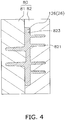
- the mold 80 for semimolten die casting the base 126 of the movable scroll 26 comprises a first mold portion 81 and a second mold portion 82. Furthermore, a pouring gate (not shown) is disposed at substantially the center of a portion corresponding to the end plate. Furthermore, as shown in FIG 4 and FIG. 5 , the following parts are formed in the second mold portion 82: a recessed part 823, which is for forming an upper part of the end plate 26a; a scroll shaped groove part 821, which is for forming the wrap 26b; and a communicating groove part 822, which is for providing communication from the scroll tail end to the inner circumferential side of the scroll shaped groove part 821.
- the scroll shaped groove part 821 is formed such that its width increases as one proceeds from the bottom part (i.e., the portion corresponding to the tip portion) to the recessed part 823. Accordingly, in the base 126 of the movable scroll 26 formed using the mold 80, the width of the portion corresponding to the wrap increases as one proceeds from the portion corresponding to the tip to the portion corresponding to the end plate. In addition, the portion formed by the communicating groove part 822 is removed in a subsequent finishing process.
- the sliding part base is heat treated after it has undergone the semimolten die casting process
- the metallographic structure of the sliding part base changes from the white cast iron structure to a metallographic structure composed of a pearlite/ferrite and lump graphite. Furthermore, the transformation of the white cast iron structure to graphite and pearlite can be adjusted by adjusting the heat treatment temperature, the hold time, the cooling rate, and the like.
- Such a metallographic structure is mainly ferrite and consequently is soft and has superior machinability; however, during machining, a built-up edge might be formed, which could reduce cutting tool life.
- a metallographic structure with a tensile strength of approximately 600-900 MPa and a hardness in the range of approximately HB 200 (i.e., HRB 96, which is the converted value based on the SAE J 417 hardness conversion table) to HB 250 (i.e., HRB 105, HRC 26, which are the converted values based on the SAE J 417 hardness conversion table; note that HRB 105 is a reference value that is used in order to exceed the effective practical range of a test type).
- a composition with a hardness equivalent to that of flake graphite cast iron has a machinability equivalent to that of flake graphite cast iron and has superior machinability compared to that of nodular graphite cast iron having an equivalent ductility and toughness.
- heat treatment is performed under conditions such that the hardness of the sliding part base becomes greater than HRB 90 (i.e., HB 176, which is the converted value based on the SAE J 417 hardness conversion table) and less than HRB 100 (i.e., HB 219, which is the converted value based on the SAE J 417 hardness conversion table).
- HRB 90 i.e., HB 176, which is the converted value based on the SAE J 417 hardness conversion table
- HRB 100 i.e., HB 219, which is the converted value based on the SAE J 417 hardness conversion table
- the sliding part base is machined, which completes the sliding part.
- FIG. 8 shows the results (as a contour diagram) of analyzing the tensile stress exerted upon the outer circumferential end groove wall.
- FIG 7 shows a time series diagram of the actual measured temperatures at the center part groove wall and the outer circumferential end groove wall of the mold 80.
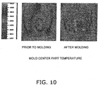
- FIG 10 shows the results of using a thermoviewer to measure the temperature of the mold 80.
- F IG. 9 shows the results (as a contour diagram) of analyzing the compressive stress exerted upon the outer circumferential end groove wall.
- the outer terminal end groove wall alternately and repetitively bears a tensile load owing to pressurization and a compressive load owing to thermal expansion; as a result, a stress of stress amplitude is created in the outer circumferential end groove wall. Furthermore, if the stress amplitude exceeds the fatigue limit of the material of the mold 80, then a fatigue failure will occur and a crack CR will be created in the outer circumferential end groove wall.
- the communicating groove part 822 is formed in the mold 80 according to the present embodiment. Consequently, the outer circumferential end groove wall, which exists in the conventional mold, does not exist in the mold 82. Accordingly, in the mold 82, it is possible to prevent the stress concentration on a part of the groove wall as well as to greatly reduce the magnitude of the stress amplitude. Thereby, if such a mold is used in semimolten die casting, semisolid die casting, or the like, it is possible to reduce the stress-induced load of the mold and, in turn, to extend the life span of the mold by tenfold or greater.
- the mold according to the present invention features a long lifespan when used to manufacture a molding using a semimolten die casting method or a semisolid die casting method and is extremely useful when manufacturing a molded part by a semimolten die casting method or a semisolid die casting method.
Landscapes
- Engineering & Computer Science (AREA)
- Mechanical Engineering (AREA)
- Rotary Pumps (AREA)
- Molds, Cores, And Manufacturing Methods Thereof (AREA)
Description
- The present invention relates to a mold for manufacturing a molding by a semimolten die casting method or a semisolid die casting method. In addition, the present invention relates to a method of using the mold to manufacture the molding by the semimolten die casting method or the semisolid die casting method.
- In the conventional art, a molding manufacturing method wherein "a preform is formed by a semimolten die casting method into a near net shape, the preform is subject to ultraprecision finishing, and thereby a target molding is obtained" has been proposed (e.g., refer to Japanese Laid-open Patent Application Publication No.
2005-36693 -
US 1 745 891 A discloses a mold comprising a plurality of first grooves, forming ribs of a cast wheel and further a second groove, forming the rim of the wheel. The second groove extends from the terminal and of each groove and after a cycle of 360° this groove nudges again with each of the first grooves. - However, when manufacturing a molding by, for example, the semimolten die casting method or the semisolid die casting method, any grooves in the mold that extend from a center part to the outer circumferential part will suffer cracks in the vicinity of their end parts on the outer circumferential part side, and the number of molding shots will be significantly fewer than that normally expected during the life of the mold, which is a problem.
- An object of the present invention is to increase the life of a mold when manufacturing a molding by a semimolten die casting method or a semisolid die casting method.
- A mold according to a first aspect of the present invention is a mold that comprises a first groove part and a second groove part. The first groove part extends with a constant length or a constant width from a center part to an outer circumferential part. The second groove part extends from a terminal end of the first groove part on the outer circumferential part side and merges with any portion of the first groove part. Furthermore, a pouring gate may be provided in the vicinity of the end part of the first groove part on the center side.
- Incidentally, in a case where a conventional mold, which comprises only the first groove part, is used in semimolten die casting, semisolid die casting, or the like, when the high temperature semimolten metal is pressurized and fills the mold, a force is generated that presses against a groove wall in the vicinity of a groove end on the outer circumferential part side of the first groove part (hereinbelow, called an "outer circumferential end groove wall"). In other words, at this time, the outer circumferential end groove wall bears a tensile load. Meanwhile, when a molded part is removed from such a mold, the temperature of the mold decreases starting from the outer circumferential side. At this time, a large temperature differential arises between the center part and the outer circumferential part of the mold, and a compressive load owing to thermal expansion is generated in the outer circumferential end groove wall. Accordingly, in such a mold, the outer circumferential end groove wall alternately and repetitively bears a tensile load owing to pressurization and a compressive load owing to thermal expansion; as a result, stress amplitude is created in the outer circumferential end groove wall. Furthermore, if the stress amplitude exceeds the fatigue limit of the material of the mold, then a fatigue failure will occur and a crack will be created in the outer circumferential end groove wall.
- However, in the mold according to the present invention, the second groove part is formed, and consequently the outer circumferential end groove wall does not exist. In other words, in this mold, the stress amplitude is not generated. Consequently, the mold according to the present invention has an increased lifespan.
- Note that, to obtain the target molding, the portion corresponding to the second groove part should be removed from the preform using a technique such as cutting.
- According to the first aspect of the present invention the first groove part is a scroll shaped groove part that extends in one direction while maintaining a scroll shape. The second groove part extends from a scroll tail end of the scroll shaped groove part and merges with any portion of the scroll shaped groove part. Furthermore, the outer periphery of the second groove part is preferably either an arc or comprises an arc and a tangent that extends from an arbitrary point along the outer periphery of the scroll shaped groove part. In addition, in this mold, the scroll shaped groove part may extend in one direction from the end surface or may extend in one direction from a recessed part (i.e., a portion corresponding to an end plate).
- In this mold, the first groove part is the scroll shaped groove part that extends in one direction while maintaining its scroll shape. Furthermore, the second groove part extends from the scroll tail of the scroll shaped groove part and merges with any portion of the scroll shaped groove part. Consequently, it is possible to increase the lifespan of a mold for a scroll member.
- According to a second aspect of the present invention, when the second groove part is viewed in the depth directions, an outer periphery of the second groove part is an arc.
- In a case where the scroll shaped groove part is formed in the mold, if the outer periphery of the second groove part is made arcuate when the second groove part is viewed in the depth directions, then it is possible to prevent the groove wall of the second groove part from bearing the tensile load owing to pressurization and the compressive load owing to thermal expansion. Consequently, the lifespan of this mold increases.
- A mold according to a third aspect of the present invention, when the second groove part is viewed in the depth directions, an outer periphery of the second groove part has an arc and a tangent, which extends from an arbitrary point along the outer periphery of the scroll shaped groove part.
- In a case where the scroll shaped groove part is formed in the mold, if the outer periphery of the second groove part comprises the arc and the tangent that extends from the arbitrary point along the outer periphery of the scroll shaped groove part when the second groove part is viewed in the depth directions, then it is possible to prevent the groove wall of the second groove part from bearing the tensile load owing to pressurization and the compressive load owing to thermal expansion. Consequently, the lifespan of this mold increases.
- A molding manufacturing method according to the present invention comprises the step of: using a mold according to any one aspect of the first through third aspects of the invention to manufacture a preform by a semimolten die casting method or a semisolid die casting method.
- Incidentally, in a case where a conventional mold, which comprises only the first groove part, is used in semimolten die casting, semisolid die casting, or the like, when the high temperature semimolten metal is pressurized and fills the mold, a force presses against the outer circumferential end groove wall of the first groove part. In other words, at this time, the outer circumferential end groove wall bears a tensile load. Meanwhile, when a molded part is removed from such a mold, the temperature of the mold decreases starting from the outer circumferential side. At this time, a large temperature differential arises between the center part and the outer circumferential part of the mold, and a compressive load owing to thermal expansion is generated in the outer circumferential end groove wall. Accordingly, in such a mold, the outer circumferential end groove wall alternately and repetitively bears a tensile load owing to pressurization and a compressive load owing to thermal expansion; as a result, stress amplitude is created in the outer circumferential end groove wall. Furthermore, if the stress amplitude exceeds the fatigue limit of the material of the mold, then a fatigue failure will occur and a crack will be created in the outer circumferential end groove wall.
- However, in the mold according to the first through fifth aspects of the present invention, the second groove part is formed, and consequently the outer circumferential end groove wall does not exist. In other words, in this mold, the stress amplitude is not generated. Consequently, the mold according to the present invention has an increased lifespan. Accordingly, using this molding manufacturing method makes it possible to reduce the cost of the mold and to manufacture such a molding inexpensively.
- The molding manufacturing method according to the present invention further comprises an eliminating process. In the eliminating process, a portion corresponding to the second groove part of the preform is removed.
- Incidentally, in a case where a conventional mold, which comprises only the first groove part, is used in semimolten die casting, semisolid die casting, or the like, when the high temperature semimolten metal is pressurized and fills the mold, a force presses against the outer circumferential end groove wall of the first groove part. In other words, at this time, the outer circumferential end groove wall bears a tensile load. Meanwhile, when a molded part is removed from such a mold, the temperature of the mold decreases starting from the outer circumferential side. At this time, a large temperature differential arises between the center part and the outer circumferential part of the mold, and a compressive load owing to thermal expansion is generated in the outer circumferential end groove wall. Accordingly, in such a mold, the outer circumferential end groove wall alternately and repetitively bears a tensile load owing to pressurization and a compressive load owing to thermal expansion; as a result, stress amplitude is created in the outer circumferential end groove wall. Furthermore, if the stress amplitude exceeds the fatigue limit of the material of the mold, then a fatigue failure will occur and a crack will be created in the outer circumferential end groove wall.
- However, in the mold according to the first through third aspects of the present invention, the second groove part is formed, and consequently the outer circumferential end groove wall does not exist. In other words, in this mold, stress amplitude is not generated. Consequently, the mold according to the present invention has an increased lifespan. Accordingly, using this molding manufacturing method makes it possible to reduce the cost of the mold and to manufacture such a molding inexpensively.
- According to a first aspect of the invention, it is possible to increase the lifespan of a mold for a scroll member.
- According to a second and third aspect of the invention, it is possible to increase the lifespan of a mold for semimolten die casting, semisolid die casting, or the like.
- The use of a molding manufacturing method according to the invention makes it possible to increase the lifespan of a mold as well as to reduce the cost of the mold and to manufacture a molding inexpensively.
-
-
FIG. 1 is a longitudinal cross sectional view of a high/low pressure dome type scroll compressor according to an embodiment of the present invention. -
FIG. 2 is a top view of a movable scroll that is incorporated into the high/low pressure dome type scroll compressor according to the embodiment of the present invention. -
FIG. 3 is a cross sectional view taken along the V-V line of the movable scroll incorporated into the high/low pressure dome type scroll compressor according to the embodiment of the present invention. -
FIG. 4 is a longitudinal cross sectional view of a mold, which is for manufacturing the movable scroll incorporated in the high/low pressure dome type scroll compressor according to an embodiment of the present invention, and a base of the movable scroll formed by semimolten die casting. -
FIG. 5 is a bottom view of an end plate of the mold and a portion on a wrap forming side of the mold for manufacturing the movable scroll that is incorporated into the high/low pressure dome type scroll compressor according to the embodiment of the present invention. -
FIG. 6 is a bottom view of an end plate and a portion on a wrap forming side of a conventional mold for manufacturing the movable scroll. -
FIG. 7 is a graph that shows a time series of actually measured temperature values when the movable scroll is formed using a conventional mold. -
FIG. 8 shows the analysis results of stress that occurs when pressure is applied to semimolten metal in the conventional mold. -
FIG. 9 shows analysis results of stress that is generated by thermal deformation in the conventional mold. -
FIG. 10 shows the results of using a thermoviewer to measure the temperature of the conventional mold. -
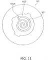
FIG. 11 is a bottom view of the end plate and a portion of the mold on the wrap forming side according to a modified example (A). -
FIG. 12 is a bottom view of the end plate and a portion of the mold on the wrap forming side according to the modified example (A). -
FIG. 13 is a bottom view of the end plate and a portion of the mold on the wrap forming side according to the modified example (A). -
FIG. 14 is a bottom view of the end plate and a portion of the mold on the wrap forming side according to the modified example (A). -
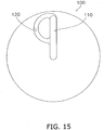
FIG. 15 is a top view of a mold portion not belonging to the present invention. -
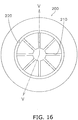
FIG. 16 is a top view of a portion of the mold-on the side whereon reinforcing ribs are formed-for manufacturing a housing. -
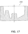
FIG. 17 is a cross sectional view taken along the V-V line of the mold for manufacturing the housing. -
FIG. 18 is a bottom view of the housing. -
FIG. 19 is a cross sectional view taken along the III-III line of the housing. - The text below explains a compressor, wherein a sliding part is used, according to an embodiment of the present invention, using a high/low pressure dome type scroll compressor as an example. Furthermore, the high/low pressure dome type compressor according to the embodiment of the present invention is designed such that it can withstand the use of a high pressure refrigerant, such as carbon dioxide refrigerant (CO2) or R410A.
- A high/low pressure dome type scroll compressor 1 according to the embodiment of the present invention comprises an evaporator, a condenser, an expansion mechanism, and the like as well as a refrigerant circuit and serves to compress a gas refrigerant inside the refrigerant circuit; furthermore, as shown in
FIG. 1 , the high/low pressure dome type scroll compressor 1 principally comprises a cylindrical hermetic dome type casing 10, ascroll compression mechanism 15, anOldham ring 39, adrive motor 16, a lower partmain bearing 60, asuction pipe 19, and adischarge pipe 20. The text below discusses the constituent parts of the high/low pressure dome type scroll compressor 1 in detail. - The
casing 10 is a hermetic container and principally comprises a substantially cylindricaltrunk casing part 11, a bowl shapedupper wall part 12, and a bowl shapedbottom wall part 13. Theupper wall part 12 is welded to an upper end part of thetrunk casing part 11. Thebottom wall part 13 is welded to a lower end part of thetrunk casing part 11. Furthermore, thecasing 10 principally houses thescroll compression mechanism 15, which compresses the gas refrigerant, and thedrive motor 16, which is disposed below thescroll compression mechanism 15. Thescroll compression mechanism 15 and thedrive motor 16 are coupled by acrankshaft 17, which is disposed inside thecasing 10 such that it extends in the vertical directions. Furthermore, as a result, agap space 18 is created between thescroll compression mechanism 15 and thedrive motor 16. - As shown in
FIG. 1 , thescroll compression mechanism 15 principally comprises: ahousing 23; a fixedscroll 24, which is disposed above thehousing 23 in tight contact therewith; and amovable scroll 26, which meshes with the fixedscroll 24. The text below discusses the constituent parts of thescroll compression mechanism 15 in detail. - The
housing 23 is press fitted and fixed, at its outer circumferential surface, to thetrunk casing part 11 completely therearound in the circumferential directions. In other words, thetrunk casing part 11 and thehousing 23 are in close contact all the way around their circumferences. Consequently, the interior of thecasing 10 is partitioned into ahigh pressure space 28 below thehousing 23 and alow pressure space 29 above thehousing 23. In addition, the fixedscroll 24 is fastened and fixed to thehousing 23 by abolt 38 such that an upper end surface of thehousing 23 is in close contact with a lower end surface of the fixedscroll 24. In addition, in thehousing 23, a housing recessedpart 31 is formed such that it provides a recess in the center of the upper surface of thehousing 23, and a bearingpart 32 is formed such that it extends below thehousing 23 from the center of the lower surface thereof. Furthermore, a bearinghole 33 is formed in the bearingpart 32 such that it passes therethrough in the vertical directions, and amain shaft part 17b of thecrankshaft 17 is rotatably inserted into the bearinghole 33 via a bearing 34. - As shown in
FIG 1 , the fixedscroll 24 principally comprises: anend plate 24a; and a scroll shaped (i.e., involute)wrap 24b, which extends downward from a mirror surface of theend plate 24a along a direction substantially orthogonal to the mirror surface. A discharge hole 41, which communicates with a compression chamber 40 (discussed below), and an enlarged recessed part 42, which communicates with the discharge hole 41, are formed in theend plate 24a. The discharge hole 41 is formed in a center portion of theend plate 24a such that it extends in the vertical directions. The enlarged recessed part 42 is formed in the upper surface of theend plate 24a such that it widens in the horizontal directions. - Furthermore, a cover body 44 is fastened and fixed to the upper surface of the fixed
scroll 24 by abolt 44a such that the cover body 44 covers the enlarged recessed part 42. Furthermore, covering the enlarged recessed part 42 with the cover body 44 forms amuffler space 45, which muffles the operation noise of thescroll compression mechanism 15. Furthermore, the fixedscroll 24 and the cover body 44 are sealed to one another by being brought into tight contact with a gasket (not shown) interposed therebetween. - The
movable scroll 26 is an outer drive type movable scroll and, as shown inFIG. 1 ,FIG 2 , andFIG 3 , principally comprises: anend plate 26a; a scroll shaped (i.e., involute)wrap 26b, which extends upward from amirror surface 26P of theend plate 26a in a direction substantially orthogonal to themirror surface 26P; abearing part 26c, which extends downward from a lower surface of theend plate 26a and fits an outer side of aneccentric shaft part 17a of thecrankshaft 17; andgroove parts 26d (refer toFIG 3 ), which are formed on opposite end parts of theend plate 26a. - Furthermore, by fitting the
Oldham ring 39 into thegroove parts 26d (refer toFIG 1 ), themovable scroll 26 is supported by thehousing 23. In addition, theeccentric shaft part 17a of thecrankshaft 17 is fitted into the bearingpart 26c. By incorporating themovable scroll 26 into thescroll compression mechanism 15 in this manner, themovable scroll 26 revolves inside thehousing 23 without rotating on its own axis by the rotation of thecrankshaft 17. Furthermore, thewrap 26b of themovable scroll 26 is meshed with thewrap 24b of the fixedscroll 24, and thereby thecompression chamber 40 is formed between the parts at which thewraps movable scroll 26 displaces thecompression chamber 40 toward its center, thereby shrinking the volume of thecompression chamber 40. In so doing, in the high/low pressure dome type scroll compressor 1, the gas refrigerant that enters thecompression chamber 40 is compressed. - In addition, in the
scroll compression mechanism 15, a communicatingpassageway 46 is formed that spans the fixedscroll 24 and thehousing 23. The communicatingpassageway 46 comprises: ascroll side passageway 47, which is formed as a notch in the fixedscroll 24; and ahousing side passageway 48, which is formed as a notch in thehousing 23. Furthermore, the upper end of the communicatingpassageway 46, namely, the upper end of thescroll side passageway 47, is open to the enlarged recessed part 42; furthermore, the lower end of the communicatingpassageway 46, namely, the lower end of thehousing side passageway 48, is open to the lower end surface of thehousing 23. In other words, the lower end opening of thehousing side passageway 48 constitutes adischarge port 49 wherethrough the refrigerant in the communicatingpassageway 46 flows out to thegap space 18. - The
Oldham ring 39 is a member for preventing themovable scroll 26 from rotating about its own axis and is fitted into Oldham grooves (not shown), which are formed in the upper surface of thehousing 23. Furthermore, the Oldham grooves are elliptical and are provided and disposed in thehousing 23 such that they oppose one another. - The
drive motor 16 is a DC motor and principally comprises: anannular stator 51, which is fixed to an inner wall surface of thecasing 10; and arotor 52, which is rotatably housed on the inner side of thestator 51 with a small gap (i.e., an air gap passageway) therebetween. Furthermore, thedrive motor 16 is disposed such that an upper end of acoil end 53, which is formed in an upper side of thestator 51, is at substantially the same height position as the lower end of the bearingpart 32 of thehousing 23. - In the
stator 51, copper wire is wound around teeth parts, and the coil ends 53 are formed above and below thestator 51. In addition, core cut parts, which are formed as notches in a plurality of locations with a prescribed spacing in circumferential directions and such that they span from the upper end surface to the lower end surface of thestator 51, are provided in the outer circumferential surface of thestator 51. Furthermore, the core cut parts form amotor cooling passageway 55, which extends in the vertical directions between thetrunk casing part 11 and thestator 51. - The
rotor 52 is drivably coupled to themovable scroll 26 of thescroll compression mechanism 15 via thecrankshaft 17, which is disposed at the axial center of thetrunk casing part 11 such that it extends in the vertical directions. In addition, aguide plate 58, which guides the refrigerant that flows out of thedischarge port 49 of the communicatingpassageway 46 to themotor cooling passageway 55, is provided and disposed in thegap space 18. - The
crankshaft 17 is a substantially columnar monolithically molded part, as shown inFIG 1 , and principally comprises theeccentric shaft part 17a, themain shaft part 17b, abalance weight part 17c, and anauxiliary shaft part 17d. Theeccentric shaft part 17a is housed in thebearing part 26c of themovable scroll 26. Themain shaft part 17b is housed in thebearing hole 33 of thehousing 23 via the bearing 34. Theauxiliary shaft part 17d is housed in the lower partmain bearing 60. - The lower part
main bearing 60 is provided and disposed in a lower space below thedrive motor 16. The lower partmain bearing 60 is fixed to thetrunk casing part 11, constitutes a lower end side bearing of thecrankshaft 17, and houses theauxiliary shaft part 17d of thecrankshaft 17. - The
suction pipe 19 is for guiding the refrigerant in the refrigerant circuit to thescroll compression mechanism 15 and is hermetically fitted to theupper wall part 12 of thecasing 10. Thesuction pipe 19 passes through thelow pressure space 29 in the vertical directions; furthermore, an inner end part of thesuction pipe 19 is fitted into the fixedscroll 24. - The
discharge pipe 20 is for discharging the refrigerant inside thecasing 10 to the outside of thecasing 10 and is hermetically fitted to thetrunk casing part 11 of thecasing 10. Furthermore, thedischarge pipe 20 comprises aninner end part 36, which is formed as a cylinder that extends in the vertical directions and is fixed to the lower end part of thehousing 23. Furthermore, the inner end opening, namely, the inflow port, of thedischarge pipe 20 is open downward. - Next, the operation of the high/low pressure dome type scroll compressor 1 will be explained in simple terms. First, when the
drive motor 16 is driven, thecrankshaft 17 rotates and themovable scroll 26 revolves without rotating about its axis. In so doing, low pressure gas refrigerant is suctioned from the circumferential edge side of thecompression chamber 40 through thesuction pipe 19 into thecompression chamber 40, is compressed as the volume of thecompression chamber 40 changes, and thereby transitions to high pressure gas refrigerant. Furthermore, the high pressure gas refrigerant is discharged from a center part of thecompression chamber 40 through the discharge hole 41 to themuffler space 45, subsequently flows out to thegap space 18 through the communicatingpassageway 46, thescroll side passageway 47, thehousing side passageway 48, and thedischarge port 49, and flows toward the lower side between theguide plate 58 and an inner surface of thetrunk casing part 11. Furthermore, when the gas refrigerant flows toward the lower side between theguide plate 58 and the inner surface of thetrunk casing part 11, a portion of the gas refrigerant splits off and flows in the circumferential directions between theguide plate 58 and thedrive motor 16. Furthermore, at this time, lubricating oil that is mixed in the gas refrigerant separates out. Moreover, another portion of the split off gas refrigerant flows toward the lower side through themotor cooling passageway 55, flows as far as a lower space of the motor, and subsequently reverses direction and flows upward through the air gap passageway between thestator 51 and therotor 52 or through themotor cooling passageway 55 on the side opposing the communicating passageway 46 (inFIG 1 , the left side). Thereafter, the gas refrigerant that passes through theguide plate 58 and the gas refrigerant that flows through the air gap passageway or themotor cooling passageway 55 merge at thegap space 18; furthermore, the merged gas refrigerant flows from theinner end part 36 of thedischarge pipe 20 into thedischarge pipe 20 and is then discharged to the outside of thecasing 10. Furthermore, the gas refrigerant that discharges to the outside of thecasing 10 circulates through the refrigerant circuit, subsequently passes through thesuction pipe 19 once again, and is suctioned into and compressed by thescroll compression mechanism 15. - In the high/low pressure dome type scroll compressor 1 according to the embodiment of the present invention, the
crankshaft 17, thehousing 23, the fixedscroll 24, themovable scroll 26, theOldham ring 39, and the lower partmain bearing 60 are the sliding parts, which are manufactured using the manufacturing method below. - A billet to which C: 2.2-2.5 wt%, Si: 1.8-2.2 wt%, Mn: 0.5-0.7 wt%, P: < 0.035 wt%, S: < 0.04 wt%, Cr: 0.00-0.50 wt%, Ni: 0.50-1.00 wt% has been added is used as the iron raw material, which is the raw material of the sliding parts in the embodiment of the present invention. Furthermore, the weight percentages herein apply to the entire amount of the material. In addition, "billet" herein means a raw material in a state after an iron raw material having the abovementioned composition is first melted in a melting furnace but before its final molding into a column using a continuous casting apparatus. Furthermore, here, the C content and the Si content are determined such that two conditions are satisfied: the tensile strength and the tensile modulus are greater than those in flake graphite cast iron; and a fluidity is provided that is appropriate to molding a sliding part base that has a complex shape. In addition, the Ni content is determined so as to constitute a metal composition that improves the toughness of the metallographic structure and is suited to preventing surface cracks during molding.
- The sliding parts according to the embodiment of the present invention are manufactured by undergoing a semimolten die casting process, a heat treatment process, a finishing process, and a partial heat treatment process. The details of each of the processes are discussed below.
- In the semimolten die casting process, first, a billet is subjected to high frequency heating so that it transitions to a semimolten state. Next, the billet in the semimolten state is poured into a prescribed mold and molded into a desired shape while a die casting machine applies a prescribed pressure, and thereby the sliding part base is obtained. Furthermore, the sliding part base is quenched and solidified inside the mold, whereupon the metallographic structure of the sliding part base is entirely transformed into white cast iron. Furthermore, the sliding part base is slightly larger than the sliding part that is ultimately obtained, and the sliding part base becomes the final sliding part after the machining allowance is removed in a subsequent finishing process.
- Furthermore, in the embodiment of the present invention, a
base 126 of themovable scroll 26 is molded using amold 80, which is shown inFIG. 4 andFIG. 5 . - As shown in
FIG. 4 , themold 80 for semimolten die casting thebase 126 of themovable scroll 26 comprises afirst mold portion 81 and asecond mold portion 82. Furthermore, a pouring gate (not shown) is disposed at substantially the center of a portion corresponding to the end plate. Furthermore, as shown inFIG 4 andFIG. 5 , the following parts are formed in the second mold portion 82: a recessedpart 823, which is for forming an upper part of theend plate 26a; a scroll shapedgroove part 821, which is for forming thewrap 26b; and a communicatinggroove part 822, which is for providing communication from the scroll tail end to the inner circumferential side of the scroll shapedgroove part 821. Furthermore, to facilitate the removal of thebase 126 of themovable scroll 26, the scroll shapedgroove part 821 is formed such that its width increases as one proceeds from the bottom part (i.e., the portion corresponding to the tip portion) to the recessedpart 823. Accordingly, in thebase 126 of themovable scroll 26 formed using themold 80, the width of the portion corresponding to the wrap increases as one proceeds from the portion corresponding to the tip to the portion corresponding to the end plate. In addition, the portion formed by the communicatinggroove part 822 is removed in a subsequent finishing process. - In the heat treatment process, the sliding part base is heat treated after it has undergone the semimolten die casting process In the heat treatment process, the metallographic structure of the sliding part base changes from the white cast iron structure to a metallographic structure composed of a pearlite/ferrite and lump graphite. Furthermore, the transformation of the white cast iron structure to graphite and pearlite can be adjusted by adjusting the heat treatment temperature, the hold time, the cooling rate, and the like. As recited in, for example, an article entitled "Research on Technology for Semimolten Casting of Iron" published in the Honda R&D Technical Review 14(1), it is possible to obtain a metallographic structure with a tensile strength of approximately 500-700 MPa and a hardness in the range of approximately HB 150 (i.e.,
HRB 81, which is the converted value based on the SAE J 417 hardness conversion table) to HB 200 (i.e., HRB 96, which is the converted value based on the SAE J 417 hardness conversion table) by holding the temperature of the metal at 950°C for 60 min. and then annealing the metal in the furnace at a cooling rate of 0.05-0.10°C/s. Such a metallographic structure is mainly ferrite and consequently is soft and has superior machinability; however, during machining, a built-up edge might be formed, which could reduce cutting tool life. In addition, by holding the metal at 1000°C for 60 min., subsequently air cooling the metal, further holding the metal for a prescribed time at a temperature somewhat lower than the initial temperature, and then air cooling the metal, it is possible to obtain a metallographic structure with a tensile strength of approximately 600-900 MPa and a hardness in the range of approximately HB 200 (i.e., HRB 96, which is the converted value based on the SAE J 417 hardness conversion table) to HB 250 (i.e., HRB 105,HRC 26, which are the converted values based on the SAE J 417 hardness conversion table; note that HRB 105 is a reference value that is used in order to exceed the effective practical range of a test type). In such a metallographic structure, a composition with a hardness equivalent to that of flake graphite cast iron has a machinability equivalent to that of flake graphite cast iron and has superior machinability compared to that of nodular graphite cast iron having an equivalent ductility and toughness. In addition, by holding the metal at a temperature of 1000°C for 60 min., subsequently oil cooling the metal, further holding the metal for a prescribed time at a temperature slightly lower than the initial temperature, and then air cooling the metal, it is possible to obtain a metallographic structure with a tensile strength of approximately 800-1300 MPa and a hardness in the range of approximately HB 250 (i.e., HRB 105,HRC 26, which are the converted values based on the SAE J 417 hardness conversion table; note that HRB 105 is a reference value that is used in order to exceed the effective practical range of a test type) to HB 350 (i.e., HRB 122, HRC 41, which are the converted values based on the SAE J 417 hardness conversion table; note that HRB 122 is a reference value that is used in order to exceed the effective practical range of a test type). Such a metallographic structure is mainly pearlite and consequently is hard and has poor machinability but superior abrasion resistance. However, the metal's excessive hardness might cause it to attack the sliding counterpart. - Note that, in the heat treatment process according to the embodiment of the present invention, heat treatment is performed under conditions such that the hardness of the sliding part base becomes greater than HRB 90 (i.e., HB 176, which is the converted value based on the SAE J 417 hardness conversion table) and less than HRB 100 (i.e., HB 219, which is the converted value based on the SAE J 417 hardness conversion table).
- In the finishing process, the sliding part base is machined, which completes the sliding part.
- The text below explains a case wherein a mold with a conventional second mold portion, as shown in
FIG. 6 , is used in semimolten die casting, semisolid die casting, and the like, referencing a mold damaging mechanism. Note that, a first mold portion is identical to the first mold portion discussed above. - First, while pressure is applied to semimolten metal at a high temperature in the
mold 80, a force is created that presses a groove wall (hereinbelow, called a "outer circumferential end groove wall") in the vicinity of a scroll tail end (i.e., the end on the outer circumferential side) of a scroll shapedgroove part 821A of asecond mold portion 82A. In other words, at this time, the outer circumferential end groove wall bears a tensile load. Furthermore,FIG. 8 shows the results (as a contour diagram) of analyzing the tensile stress exerted upon the outer circumferential end groove wall. - Next, the transfer of heat from the high temperature semimolten metal filling the
mold 80 rapidly raises the temperature of themold 80; after several seconds, when the molded part is removed, the temperature of themold 80 falls starting from the outer circumferential side. Furthermore,FIG 7 shows a time series diagram of the actual measured temperatures at the center part groove wall and the outer circumferential end groove wall of themold 80. In addition,FIG 10 shows the results of using a thermoviewer to measure the temperature of themold 80. - Furthermore, when a large temperature differential arises between the center part groove wall and the outer circumferential end groove wall of the
mold 80 in this manner, a compressive load owing to thermal expansion is exerted upon the outer circumferential end groove wall. Furthermore, FIG. 9 shows the results (as a contour diagram) of analyzing the compressive stress exerted upon the outer circumferential end groove wall. - Accordingly, in such a
mold 80, the outer terminal end groove wall alternately and repetitively bears a tensile load owing to pressurization and a compressive load owing to thermal expansion; as a result, a stress of stress amplitude is created in the outer circumferential end groove wall. Furthermore, if the stress amplitude exceeds the fatigue limit of the material of themold 80, then a fatigue failure will occur and a crack CR will be created in the outer circumferential end groove wall. - The communicating
groove part 822 is formed in themold 80 according to the present embodiment. Consequently, the outer circumferential end groove wall, which exists in the conventional mold, does not exist in themold 82. Accordingly, in themold 82, it is possible to prevent the stress concentration on a part of the groove wall as well as to greatly reduce the magnitude of the stress amplitude. Thereby, if such a mold is used in semimolten die casting, semisolid die casting, or the like, it is possible to reduce the stress-induced load of the mold and, in turn, to extend the life span of the mold by tenfold or greater. -
- (A) In the
mold 80 according to the above embodiment, the communicatinggroove part 822 of thesecond mold portion 82 is shaped as shown inFIG 5 , but the shape of the communicating groove part is not particularly limited thereto; for example, communicatinggroove parts FIG. 11 through FIG 14 may be formed. Furthermore, based on the results of stress analysis (taking into consideration the mean stress, the stress amplitude, a safety factor with respect to the fatigue limit, and the like), the shapes shown inFIG. 13 andFIG. 14 , namely, the shapes of the communicatinggroove parts FIG 13 , the outer peripheries of the scroll shapedgroove part 821 and the communicatinggroove part 822C have a nearly arcuate shape in a bottom view. In addition, inFIG 14 , the outer periphery of the communicatinggroove part 822D in a bottom view has an arc and a tangent, which extends from a point on the outer periphery of the scroll shapedgroove part 821. - (B) In the above embodiment, the present invention is adapted to a mold for molding the
movable scroll 26, but the present invention may also be adapted to a mold for molding other components such as a fixed scroll or a housing. Amold portion 100 not belonging to the invention and as shown inFIG. 15 may be used to mold a flat plate member. Note that, in such a case, agroove part 110 corresponds to a molded part portion and agroove part 120 is a communicating groove part and corresponds to a portion to be removed by machining and the like. In addition, amold 200 as shown inFIG. 16 andFIG. 17 may be used to mold, for example, ahousing 250 that comprises reinforcingribs 251 as shown inFIG. 18 and FIG. 19 . Note that, in such a case,groove parts 210 correspond to the reinforcingribs 251 and agroove part 220 is a communicating groove part and corresponds to a portion to be removed by machining and the like. - (C) The above embodiment adopts a hermetic type compressor as the high/low pressure dome type scroll compressor 1, but the high/low pressure dome type scroll compressor 1 may be a high pressure dome type compressor or a lower pressure dome type compressor. In addition, it may be a semihermetic type compressor or an open type compressor.
- (D) In the above embodiment, a billet to which C: 2.2-2.5 wt%, Si: 1.8-2.2 wt%, Mn: 0.5-0.7 wt%, P: < 0.035 wt%, S: < 0.04 wt%, Cr: 0.00-0.50 wt%, Ni: 0.50-1.00 wt% has been added is used as the iron raw material, but the percentages of the elements in the iron raw material can be determined arbitrarily as long as the percentages do not depart from the spirit of the invention.
- (E) In the above embodiment, the
Oldham ring 39 is used as the rotation preventing mechanism, but any mechanism, such as a pin, a ball coupling, or a crank, may be used as the rotation preventing mechanism. - (F) The above embodiment described an exemplary case wherein the scroll compressor 1 is used inside the refrigerant circuit, but the application of the scroll compressor 1 is not limited to air conditioning, and the present invention can also be adapted to a compressor, a fan, a supercharger, a pump, or the like-either as a standalone or embedded in a system.
- (G) In the scroll compressor 1 according to the above embodiment, lubricating oil is present, but the scroll compressor 1 may be an oilless or oil-free (i.e., with or without oil) type compressor, fan, supercharger, or pump.
- (H) The high/low pressure dome type scroll compressor 1 according to the above embodiment is an outer drive type scroll compressor but may be an inner drive type scroll compressor.
- (I) In the
movable scroll 26 according to the above embodiment, the notches are formed by, for example, end milling, but a notch (i.e., counterbore) may be preformed by a semimolten die casting process in the center portion of the upper surface of theend plate 26a of themovable scroll 26 shown inFIG. 5 . - (J) In the above embodiment, iron raw material is used as the raw material of the sliding parts, but a metal material other than iron may be used as it does not depart from the spirit of the invention.
- The mold according to the present invention features a long lifespan when used to manufacture a molding using a semimolten die casting method or a semisolid die casting method and is extremely useful when manufacturing a molded part by a semimolten die casting method or a semisolid die casting method.
-
- 82
- Second mold portion of mold (mold)
- 100,200
- Mold portions (molds)
- 110
- Groove part corresponding to molded part (first groove part)
- 210
- Groove part corresponding to reinforcing rib (first groove part)
- 120, 220
- Communicating groove parts (second groove parts)
- 126
- Base of movable scroll (preform)
- 821
- Scroll shaped groove part (first groove part)
- 822, 822A, 822B, 822C, 822D
- Communicating groove parts (second groove parts)
- Japanese Laid-open Patent Application Publication No.
2005-36693
Claims (4)
- A mold (82, 100), comprising:a first groove part (110, 821), which extends with a constant length or a constant width from a center part to an outer circumferential part, the first groove part being a scroll shaped groove part that extends in one direction while maintaining a scroll shape; anda second groove part (120, 822, 822A, 822B, 822C, 822D) extending from a terminal end of the first groove part on the outer circumferential part side and merging with any portion of the first groove part, and the second groove part extending from a scroll tail end of the scroll shaped groove part and merging with any portion of the scroll shaped groove part.
- A mold according to claim 1, wherein
when the second groove part is viewed in the depth directions, an outer periphery of the second groove part is an arc. - A mold according to claim 1, wherein
when the second groove part is viewed in the depth directions, an outer periphery of the second groove part has an arc and a tangent, which extends from an arbitrary point along the outer periphery of the scroll shaped groove part. - A molding manufacturing method, comprising the step of:using a mold according to any one claim of claim 1 through claim 3 to manufacture a preform (126) by a semimolten die casting method or a semisolid die casting method,further comprising
an eliminating process, wherein a portion corresponding to the second groove part of the preform is removed.
Applications Claiming Priority (2)
| Application Number | Priority Date | Filing Date | Title |
|---|---|---|---|
| JP2008162058A JP4493704B2 (en) | 2008-06-20 | 2008-06-20 | Mold and molded body manufacturing method |
| PCT/JP2009/002807 WO2009154005A1 (en) | 2008-06-20 | 2009-06-19 | Die and production method for molding |
Publications (3)
| Publication Number | Publication Date |
|---|---|
| EP2305398A1 EP2305398A1 (en) | 2011-04-06 |
| EP2305398A4 EP2305398A4 (en) | 2017-04-12 |
| EP2305398B1 true EP2305398B1 (en) | 2018-08-22 |
Family
ID=41433923
Family Applications (1)
| Application Number | Title | Priority Date | Filing Date |
|---|---|---|---|
| EP09766453.6A Not-in-force EP2305398B1 (en) | 2008-06-20 | 2009-06-19 | Die and production method for molding |
Country Status (5)
| Country | Link |
|---|---|
| US (2) | US8607846B2 (en) |
| EP (1) | EP2305398B1 (en) |
| JP (1) | JP4493704B2 (en) |
| CA (1) | CA2727913C (en) |
| WO (1) | WO2009154005A1 (en) |
Families Citing this family (2)
| Publication number | Priority date | Publication date | Assignee | Title |
|---|---|---|---|---|
| JP6036797B2 (en) * | 2014-12-12 | 2016-11-30 | ダイキン工業株式会社 | Scroll compressor |
| CN105921714A (en) * | 2016-06-14 | 2016-09-07 | 昆山莱捷有色金属有限公司 | Mold connecting sleeve improvement structure |
Family Cites Families (11)
| Publication number | Priority date | Publication date | Assignee | Title |
|---|---|---|---|---|
| US1745891A (en) * | 1926-09-11 | 1930-02-04 | Permold Co | Apparatus for casting metal articles |
| JPH06210426A (en) * | 1992-03-04 | 1994-08-02 | Mitsubishi Electric Corp | Casting manufacturing method and manufacturing apparatus |
| JP3785646B2 (en) * | 1994-12-02 | 2006-06-14 | 株式会社デンソー | Scroll casting method and compressor for compressor |
| US5580401A (en) * | 1995-03-14 | 1996-12-03 | Copeland Corporation | Gray cast iron system for scroll machines |
| JP3601203B2 (en) * | 1996-09-06 | 2004-12-15 | 松下電器産業株式会社 | Movable scroll of scroll compressor and method of manufacturing the same |
| JP2002219553A (en) * | 2001-01-29 | 2002-08-06 | Toyota Industries Corp | Casting device, cast-formed article, and scroll |
| JP2002310074A (en) * | 2001-04-17 | 2002-10-23 | Toyota Industries Corp | Casting device for compressor scroll and scroll |
| JP2004017100A (en) * | 2002-06-17 | 2004-01-22 | Asahi Tec Corp | Method for manufacturing vehicle wheel |
| KR100436116B1 (en) * | 2003-04-24 | 2004-06-16 | 홍준표 | Manufacturing apparatus of billet for thixocasting method |
| JP2005023817A (en) * | 2003-07-01 | 2005-01-27 | Matsushita Electric Ind Co Ltd | Scroll compressor and method for processing scroll wrap |
| JP2005036693A (en) | 2003-07-18 | 2005-02-10 | Hitachi Home & Life Solutions Inc | Manufacturing method of refrigerant compressor |
-
2008
- 2008-06-20 JP JP2008162058A patent/JP4493704B2/en not_active Expired - Fee Related
-
2009
- 2009-06-19 CA CA2727913A patent/CA2727913C/en active Active
- 2009-06-19 EP EP09766453.6A patent/EP2305398B1/en not_active Not-in-force
- 2009-06-19 WO PCT/JP2009/002807 patent/WO2009154005A1/en not_active Ceased
- 2009-06-19 US US12/999,664 patent/US8607846B2/en not_active Expired - Fee Related
-
2013
- 2013-09-18 US US14/030,203 patent/US8708030B2/en active Active
Non-Patent Citations (1)
| Title |
|---|
| None * |
Also Published As
| Publication number | Publication date |
|---|---|
| US20140014287A1 (en) | 2014-01-16 |
| EP2305398A1 (en) | 2011-04-06 |
| CA2727913C (en) | 2014-11-18 |
| WO2009154005A1 (en) | 2009-12-23 |
| CA2727913A1 (en) | 2009-12-23 |
| US20110088863A1 (en) | 2011-04-21 |
| JP2010000525A (en) | 2010-01-07 |
| JP4493704B2 (en) | 2010-06-30 |
| US8708030B2 (en) | 2014-04-29 |
| EP2305398A4 (en) | 2017-04-12 |
| US8607846B2 (en) | 2013-12-17 |
Similar Documents
| Publication | Publication Date | Title |
|---|---|---|
| KR101122533B1 (en) | Sliding component of compressor, sliding component base, scroll component, and compressor | |
| EP1998046B1 (en) | Compressor and its manufacturing method | |
| EP1980752B1 (en) | Injection molded scroll form | |
| JP2005036693A (en) | Manufacturing method of refrigerant compressor | |
| US8708030B2 (en) | Mold | |
| JP2011127446A (en) | Method for manufacturing scroll part | |
| RU2387878C1 (en) | Sliding compressor element, sliding element base, spiral element and compressor | |
| JP2008088860A (en) | Compressor sliding parts, scroll parts, crankshaft parts, rotation prevention members, and swing compressor piston parts | |
| JP2007309146A (en) | Compressor | |
| JP2009270568A (en) | Bearing housing | |
| JP2010048345A (en) | Sliding member manufacturing method | |
| JP4821526B2 (en) | Scroll member of compressor and compressor using the same | |
| JP2009174394A (en) | Scroll component manufacturing method, scroll component, and scroll compressor | |
| JPH03242490A (en) | Molding method for oil sump groove on edge of aluminum alloy rotor | |
| CN112324657A (en) | Scroll, preparation method of scroll, and scroll compressor | |
| JPH03111531A (en) | Rotor made of aluminum alloy | |
| US10989139B2 (en) | Crankcase for a reciprocating piston engine, in particular of a motor vehicle | |
| JP2007263107A (en) | Compressor sliding parts | |
| CN121782165A (en) | Scroll compressor and refrigeration apparatus | |
| JPH06304691A (en) | Manufacture of aluminum alloy-made rotor | |
| JPH03165948A (en) | Manufacture of aluminum alloy-made rotor | |
| JP2007309145A (en) | Compressor and manufacturing method thereof |
Legal Events
| Date | Code | Title | Description |
|---|---|---|---|
| PUAI | Public reference made under article 153(3) epc to a published international application that has entered the european phase |
Free format text: ORIGINAL CODE: 0009012 |
|
| 17P | Request for examination filed |
Effective date: 20110117 |
|
| AK | Designated contracting states |
Kind code of ref document: A1 Designated state(s): AT BE BG CH CY CZ DE DK EE ES FI FR GB GR HR HU IE IS IT LI LT LU LV MC MK MT NL NO PL PT RO SE SI SK TR |
|
| AX | Request for extension of the european patent |
Extension state: AL BA RS |
|
| DAX | Request for extension of the european patent (deleted) | ||
| RA4 | Supplementary search report drawn up and despatched (corrected) |
Effective date: 20170315 |
|
| RIC1 | Information provided on ipc code assigned before grant |
Ipc: B22C 9/06 20060101ALI20170309BHEP Ipc: B22D 17/22 20060101AFI20170309BHEP Ipc: B22D 17/00 20060101ALI20170309BHEP |
|
| GRAP | Despatch of communication of intention to grant a patent |
Free format text: ORIGINAL CODE: EPIDOSNIGR1 |
|
| STAA | Information on the status of an ep patent application or granted ep patent |
Free format text: STATUS: GRANT OF PATENT IS INTENDED |
|
| INTG | Intention to grant announced |
Effective date: 20180314 |
|
| GRAS | Grant fee paid |
Free format text: ORIGINAL CODE: EPIDOSNIGR3 |
|
| GRAA | (expected) grant |
Free format text: ORIGINAL CODE: 0009210 |
|
| STAA | Information on the status of an ep patent application or granted ep patent |
Free format text: STATUS: THE PATENT HAS BEEN GRANTED |
|
| AK | Designated contracting states |
Kind code of ref document: B1 Designated state(s): AT BE BG CH CY CZ DE DK EE ES FI FR GB GR HR HU IE IS IT LI LT LU LV MC MK MT NL NO PL PT RO SE SI SK TR |
|
| REG | Reference to a national code |
Ref country code: GB Ref legal event code: FG4D |
|
| REG | Reference to a national code |
Ref country code: CH Ref legal event code: EP |
|
| REG | Reference to a national code |
Ref country code: AT Ref legal event code: REF Ref document number: 1031875 Country of ref document: AT Kind code of ref document: T Effective date: 20180915 |
|
| REG | Reference to a national code |
Ref country code: IE Ref legal event code: FG4D |
|
| REG | Reference to a national code |
Ref country code: DE Ref legal event code: R096 Ref document number: 602009054029 Country of ref document: DE |
|
| REG | Reference to a national code |
Ref country code: NL Ref legal event code: MP Effective date: 20180822 |
|
| REG | Reference to a national code |
Ref country code: LT Ref legal event code: MG4D |
|
| PG25 | Lapsed in a contracting state [announced via postgrant information from national office to epo] |
Ref country code: NO Free format text: LAPSE BECAUSE OF FAILURE TO SUBMIT A TRANSLATION OF THE DESCRIPTION OR TO PAY THE FEE WITHIN THE PRESCRIBED TIME-LIMIT Effective date: 20181122 Ref country code: GR Free format text: LAPSE BECAUSE OF FAILURE TO SUBMIT A TRANSLATION OF THE DESCRIPTION OR TO PAY THE FEE WITHIN THE PRESCRIBED TIME-LIMIT Effective date: 20181123 Ref country code: IS Free format text: LAPSE BECAUSE OF FAILURE TO SUBMIT A TRANSLATION OF THE DESCRIPTION OR TO PAY THE FEE WITHIN THE PRESCRIBED TIME-LIMIT Effective date: 20181222 Ref country code: LT Free format text: LAPSE BECAUSE OF FAILURE TO SUBMIT A TRANSLATION OF THE DESCRIPTION OR TO PAY THE FEE WITHIN THE PRESCRIBED TIME-LIMIT Effective date: 20180822 Ref country code: NL Free format text: LAPSE BECAUSE OF FAILURE TO SUBMIT A TRANSLATION OF THE DESCRIPTION OR TO PAY THE FEE WITHIN THE PRESCRIBED TIME-LIMIT Effective date: 20180822 Ref country code: BG Free format text: LAPSE BECAUSE OF FAILURE TO SUBMIT A TRANSLATION OF THE DESCRIPTION OR TO PAY THE FEE WITHIN THE PRESCRIBED TIME-LIMIT Effective date: 20181122 Ref country code: SE Free format text: LAPSE BECAUSE OF FAILURE TO SUBMIT A TRANSLATION OF THE DESCRIPTION OR TO PAY THE FEE WITHIN THE PRESCRIBED TIME-LIMIT Effective date: 20180822 Ref country code: FI Free format text: LAPSE BECAUSE OF FAILURE TO SUBMIT A TRANSLATION OF THE DESCRIPTION OR TO PAY THE FEE WITHIN THE PRESCRIBED TIME-LIMIT Effective date: 20180822 |
|
| REG | Reference to a national code |
Ref country code: AT Ref legal event code: MK05 Ref document number: 1031875 Country of ref document: AT Kind code of ref document: T Effective date: 20180822 |
|
| PG25 | Lapsed in a contracting state [announced via postgrant information from national office to epo] |
Ref country code: ES Free format text: LAPSE BECAUSE OF FAILURE TO SUBMIT A TRANSLATION OF THE DESCRIPTION OR TO PAY THE FEE WITHIN THE PRESCRIBED TIME-LIMIT Effective date: 20180822 Ref country code: HR Free format text: LAPSE BECAUSE OF FAILURE TO SUBMIT A TRANSLATION OF THE DESCRIPTION OR TO PAY THE FEE WITHIN THE PRESCRIBED TIME-LIMIT Effective date: 20180822 Ref country code: LV Free format text: LAPSE BECAUSE OF FAILURE TO SUBMIT A TRANSLATION OF THE DESCRIPTION OR TO PAY THE FEE WITHIN THE PRESCRIBED TIME-LIMIT Effective date: 20180822 |
|
| PG25 | Lapsed in a contracting state [announced via postgrant information from national office to epo] |
Ref country code: EE Free format text: LAPSE BECAUSE OF FAILURE TO SUBMIT A TRANSLATION OF THE DESCRIPTION OR TO PAY THE FEE WITHIN THE PRESCRIBED TIME-LIMIT Effective date: 20180822 Ref country code: PL Free format text: LAPSE BECAUSE OF FAILURE TO SUBMIT A TRANSLATION OF THE DESCRIPTION OR TO PAY THE FEE WITHIN THE PRESCRIBED TIME-LIMIT Effective date: 20180822 Ref country code: AT Free format text: LAPSE BECAUSE OF FAILURE TO SUBMIT A TRANSLATION OF THE DESCRIPTION OR TO PAY THE FEE WITHIN THE PRESCRIBED TIME-LIMIT Effective date: 20180822 Ref country code: CZ Free format text: LAPSE BECAUSE OF FAILURE TO SUBMIT A TRANSLATION OF THE DESCRIPTION OR TO PAY THE FEE WITHIN THE PRESCRIBED TIME-LIMIT Effective date: 20180822 Ref country code: RO Free format text: LAPSE BECAUSE OF FAILURE TO SUBMIT A TRANSLATION OF THE DESCRIPTION OR TO PAY THE FEE WITHIN THE PRESCRIBED TIME-LIMIT Effective date: 20180822 |
|
| REG | Reference to a national code |
Ref country code: DE Ref legal event code: R097 Ref document number: 602009054029 Country of ref document: DE |
|
| PG25 | Lapsed in a contracting state [announced via postgrant information from national office to epo] |
Ref country code: SK Free format text: LAPSE BECAUSE OF FAILURE TO SUBMIT A TRANSLATION OF THE DESCRIPTION OR TO PAY THE FEE WITHIN THE PRESCRIBED TIME-LIMIT Effective date: 20180822 Ref country code: DK Free format text: LAPSE BECAUSE OF FAILURE TO SUBMIT A TRANSLATION OF THE DESCRIPTION OR TO PAY THE FEE WITHIN THE PRESCRIBED TIME-LIMIT Effective date: 20180822 |
|
| PLBE | No opposition filed within time limit |
Free format text: ORIGINAL CODE: 0009261 |
|
| STAA | Information on the status of an ep patent application or granted ep patent |
Free format text: STATUS: NO OPPOSITION FILED WITHIN TIME LIMIT |
|
| 26N | No opposition filed |
Effective date: 20190523 |
|
| PG25 | Lapsed in a contracting state [announced via postgrant information from national office to epo] |
Ref country code: SI Free format text: LAPSE BECAUSE OF FAILURE TO SUBMIT A TRANSLATION OF THE DESCRIPTION OR TO PAY THE FEE WITHIN THE PRESCRIBED TIME-LIMIT Effective date: 20180822 |
|
| REG | Reference to a national code |
Ref country code: DE Ref legal event code: R119 Ref document number: 602009054029 Country of ref document: DE |
|
| PG25 | Lapsed in a contracting state [announced via postgrant information from national office to epo] |
Ref country code: MC Free format text: LAPSE BECAUSE OF FAILURE TO SUBMIT A TRANSLATION OF THE DESCRIPTION OR TO PAY THE FEE WITHIN THE PRESCRIBED TIME-LIMIT Effective date: 20180822 |
|
| REG | Reference to a national code |
Ref country code: CH Ref legal event code: PL |
|
| REG | Reference to a national code |
Ref country code: BE Ref legal event code: MM Effective date: 20190630 |
|
| PG25 | Lapsed in a contracting state [announced via postgrant information from national office to epo] |
Ref country code: TR Free format text: LAPSE BECAUSE OF FAILURE TO SUBMIT A TRANSLATION OF THE DESCRIPTION OR TO PAY THE FEE WITHIN THE PRESCRIBED TIME-LIMIT Effective date: 20180822 |
|
| PG25 | Lapsed in a contracting state [announced via postgrant information from national office to epo] |
Ref country code: DE Free format text: LAPSE BECAUSE OF NON-PAYMENT OF DUE FEES Effective date: 20200101 Ref country code: IE Free format text: LAPSE BECAUSE OF NON-PAYMENT OF DUE FEES Effective date: 20190619 |
|
| PG25 | Lapsed in a contracting state [announced via postgrant information from national office to epo] |
Ref country code: LU Free format text: LAPSE BECAUSE OF NON-PAYMENT OF DUE FEES Effective date: 20190619 Ref country code: LI Free format text: LAPSE BECAUSE OF NON-PAYMENT OF DUE FEES Effective date: 20190630 Ref country code: BE Free format text: LAPSE BECAUSE OF NON-PAYMENT OF DUE FEES Effective date: 20190630 Ref country code: CH Free format text: LAPSE BECAUSE OF NON-PAYMENT OF DUE FEES Effective date: 20190630 |
|
| PG25 | Lapsed in a contracting state [announced via postgrant information from national office to epo] |
Ref country code: PT Free format text: LAPSE BECAUSE OF FAILURE TO SUBMIT A TRANSLATION OF THE DESCRIPTION OR TO PAY THE FEE WITHIN THE PRESCRIBED TIME-LIMIT Effective date: 20181222 |
|
| PG25 | Lapsed in a contracting state [announced via postgrant information from national office to epo] |
Ref country code: CY Free format text: LAPSE BECAUSE OF FAILURE TO SUBMIT A TRANSLATION OF THE DESCRIPTION OR TO PAY THE FEE WITHIN THE PRESCRIBED TIME-LIMIT Effective date: 20180822 |
|
| PG25 | Lapsed in a contracting state [announced via postgrant information from national office to epo] |
Ref country code: MT Free format text: LAPSE BECAUSE OF FAILURE TO SUBMIT A TRANSLATION OF THE DESCRIPTION OR TO PAY THE FEE WITHIN THE PRESCRIBED TIME-LIMIT Effective date: 20180822 Ref country code: HU Free format text: LAPSE BECAUSE OF FAILURE TO SUBMIT A TRANSLATION OF THE DESCRIPTION OR TO PAY THE FEE WITHIN THE PRESCRIBED TIME-LIMIT; INVALID AB INITIO Effective date: 20090619 |
|
| PGFP | Annual fee paid to national office [announced via postgrant information from national office to epo] |
Ref country code: IT Payment date: 20210625 Year of fee payment: 13 Ref country code: FR Payment date: 20210622 Year of fee payment: 13 |
|
| PGFP | Annual fee paid to national office [announced via postgrant information from national office to epo] |
Ref country code: GB Payment date: 20210625 Year of fee payment: 13 |
|
| PG25 | Lapsed in a contracting state [announced via postgrant information from national office to epo] |
Ref country code: MK Free format text: LAPSE BECAUSE OF FAILURE TO SUBMIT A TRANSLATION OF THE DESCRIPTION OR TO PAY THE FEE WITHIN THE PRESCRIBED TIME-LIMIT Effective date: 20180822 |
|
| GBPC | Gb: european patent ceased through non-payment of renewal fee |
Effective date: 20220619 |
|
| PG25 | Lapsed in a contracting state [announced via postgrant information from national office to epo] |
Ref country code: FR Free format text: LAPSE BECAUSE OF NON-PAYMENT OF DUE FEES Effective date: 20220630 |
|
| PG25 | Lapsed in a contracting state [announced via postgrant information from national office to epo] |
Ref country code: GB Free format text: LAPSE BECAUSE OF NON-PAYMENT OF DUE FEES Effective date: 20220619 |
|
| PG25 | Lapsed in a contracting state [announced via postgrant information from national office to epo] |
Ref country code: IT Free format text: LAPSE BECAUSE OF NON-PAYMENT OF DUE FEES Effective date: 20220619 |