EP2304865B1 - Electric machine - Google Patents
Electric machine Download PDFInfo
- Publication number
- EP2304865B1 EP2304865B1 EP09769137.2A EP09769137A EP2304865B1 EP 2304865 B1 EP2304865 B1 EP 2304865B1 EP 09769137 A EP09769137 A EP 09769137A EP 2304865 B1 EP2304865 B1 EP 2304865B1
- Authority
- EP
- European Patent Office
- Prior art keywords
- claw
- electric machine
- pole
- machine according
- wall
- Prior art date
- Legal status (The legal status is an assumption and is not a legal conclusion. Google has not performed a legal analysis and makes no representation as to the accuracy of the status listed.)
- Active
Links
Images


Classifications
-
- H—ELECTRICITY
- H02—GENERATION; CONVERSION OR DISTRIBUTION OF ELECTRIC POWER
- H02K—DYNAMO-ELECTRIC MACHINES
- H02K3/00—Details of windings
- H02K3/46—Fastening of windings on the stator or rotor structure
- H02K3/52—Fastening salient pole windings or connections thereto
- H02K3/527—Fastening salient pole windings or connections thereto applicable to rotors only
- H02K3/528—Fastening salient pole windings or connections thereto applicable to rotors only of the claw-pole type
Definitions
- the invention relates to an electric machine, in particular AC or three-phase generator having a rotor which is designed as a claw-pole rotor. Between the two Klauenpolplatinen a coil carrier is arranged, which carries a field winding The field winding has two connection conductors, which are each electrically connected to a power supply element attached to the rotor (for example, slip ring).
- the invention relates to the fixation of the connecting conductor to a fixing section. For example, from the US writings US 6,172,434 B1 . US 6,107,719 and US 5,898,252 It is already known how the connection wires can be fastened without the centrifugal force acting on different sections of the connection conductors becoming too large.
- An electric machine which has a coil carrier.
- the excitation winding is wound around this coil carrier.
- the bobbin has a wall from which a fixing portion extends.
- a connection conductor is wound in the rotational axis direction of the rotor.
- An electric machine which has a coil carrier. To this coil carrier is wound there, the exciter winding.
- the bobbin has a wall from which a fixing portion extends. This fixation section is also located between two homopolar claw poles of the rotor.
- fixation sections is therefore the task of making the one or more fixation sections such that forces are reduced.
- the electrical machine according to the invention with the features of the independent claim has the advantage that the arrangement of the fixing section between the coil carrier and the claw pole plate, the effective radius for this attachment point can be reduced. Centrifugal forces are inevitably reduced. In this context, lower strength material can be used, so that ultimately higher temperatures can no longer be considered particularly critical because of the reduced influence of centrifugal force.
- the undercuts of the fixing section are formed by arms, wherein one of the arms has a substantially shorter radial length than the other arm.
- This arrangement has the advantage that the connection conductor can be arranged at this point and passed as short as possible past each other.
- the connecting conductor is wound around at least three sides of the fixing section, this results in a particularly good utilization of possible frictional forces for preventing excessive centrifugal forces and, on the other hand, it is possible to guide the connecting wire almost radially outward.
- This has the advantage, for example, that the connecting wires do not widen the coil unnecessarily, for example by angled wire layers. The transport of prefabricated semi-finished products from coil carriers with excitation winding is thereby simplified.
- a part of the fixing section between the exciter winding and to arrange one of the claw pole boards there is the advantage that of the two claw pole boards, which face each other, a pressure in the axial direction (axis of rotation of the rotor) can be exerted on the fixing portion.
- the arm (s) are pressed onto the lead wire wound around the fixing portion. It is thus very simply prevented that the centrifugal forces are too large.
- the part of the fixing portion, which is arranged between the excitation winding and one of the claw-pole boards is positioned in a recess which is incorporated in the claw-pole board.
- the connecting wire is surrounded by a flexible hose over part of the length wound around the fixing section, a particularly gentle force transmission to the connecting wire is possible.
- the flexible hose has the advantage that when clamping the wire between an arm and the wall under the influence of Rotation not only stiction between wire, hose and wall or arm is generated, but by the flexibility at the same time in a certain way a positive connection between wall, arm and wire is generated.
- the tube consists of fabric or foam material or other compliant material than a directly applied to the wire paint insulation.
- the other connecting conductor is preferably guided by a slot in the wall of the bobbin directly on the annular body portion of the bobbin. It is envisaged that the claw-pole fingers extend either in the axial or radial direction (radial-flow or axial-flow machine).
- the mass of the fastening and wire system can be reduced, so that the loads in the coil carrier are reduced. Accordingly, for example, lower strength material (typically cheaper in price or with lower material thicknesses) may be used (lighter weight, lower cost).
- lower strength material typically cheaper in price or with lower material thicknesses
- the displacement of the attachment point between the claw-pole plate and the wall reduces the influence of pulsating movement many times, so that the risk of fatigue fractures is significantly lower.
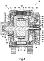
- FIG. 1 is a cross section through an electric machine 10, shown here in the embodiment as a generator or alternator for motor vehicle.
- This electrical machine 10 has, inter alia, a two-part housing 13, which consists of a first bearing plate 13.1 and a second bearing plate 13.2.
- the bearing plate 13.1 and the bearing plate 13.2 take in a so-called stator 16, on the one hand consists of a substantially annular stator iron 17, and in whose radially inwardly directed, axially extending grooves, a stator winding 18 is inserted.
- This annular stator 16 surrounds with its radially inwardly directed grooved surface a rotor 20 which is formed as a claw-pole rotor.
- the rotor 20 consists, inter alia, of two claw-pole plates 22 and 23, on whose outer circumference in each case axially extending claw-pole fingers 24 and 25 are arranged. Both claw-pole plates 22 and 23 are arranged in the rotor 20 such that their claw-pole fingers 24 and 25, which extend in the axial direction, alternate with one another on the circumference of the rotor 20. This results in magnetically required spaces between the oppositely magnetized claw pole fingers 24 and 25, which are referred to as Klauenpol formatschreib.
- the rotor 20 is rotatably supported in the respective end shields 13.1 and 13.2, respectively, by means of a shaft 27 and one respective rolling bearing 28 located on each side of the rotor.
- the rotor 20 has a total of two axial end faces, on each of which a fan 30 is attached.
- This fan 30 consists essentially of a plate-shaped or disc-shaped portion, emanating from the fan blades in a known manner.
- These fans 30 serve to allow an air exchange between the outside of the electric machine 10 and the interior of the electric machine 10 via openings 40 in the end shields 13.1 and 13.2.
- the openings 40 are provided substantially at the axial ends of the end shields 13.1 and 13.2, via the means of the fan 30th Cooling air is sucked into the interior of the electric machine 10. This cooling air is accelerated by the rotation of the fan 30 radially outward, so that they can pass through the cool air-permeable winding overhang 45 therethrough. By this effect, the winding overhang 45 is cooled.
- the cooling air takes after passing through the winding overhang 45 and after flowing around this winding overhang 45 a way radially outward, through here in this FIG. 1 not shown openings.
- this protective cap 47 which protects various components against environmental influences.
- this protective cap 47 covers, for example, a so-called slip ring assembly 49, which serves to supply a field winding 51 with exciter current.
- a heat sink 53 Around this slip ring assembly 49 around a heat sink 53 is arranged, which acts as a positive heat sink here.
- the bearing plate acts 13.2.
- a connection plate 56 is arranged, which serves to connect arranged in the bearing plate 13.2 minus diodes 58 and not shown here in this illustration plus diodes in the heat sink 53 together and thus represent a known bridge circuit.
- a bobbin 60 is disposed radially outside of a pole core 63.
- the bobbin 60 has the task to isolate the excitation winding 51 both against the Klauenpolplatinen 22 and 23 and on the other hand in the context of prefabrication as a shaping element especially after the winding process is completed with respect to the exciter winding wire to act.
- the bobbin 60 is thereby pushed with two connecting conductors 66 axially over the pole core 63 and subsequently axially fixed between the two jaw pallets 22 and 23.
- the claw-pole fingers 24 and 25 engage over the exciter winding 51 and thus form a kind of cage radially outward, which prevents an impermissible radial displacement of the exciter winding 51.
- the connecting conductor 66 in Fig. 1 is shown only one, are passed between two Klauenpolfingern 25, ie between two so-called Polwurzeln, on the Klauenpolplatine 23 and ultimately passed radially inward toward a contact surface unspecified here.
- the connection conductor or the connection conductor 66 is fixed contact (contact, soldered, soldered).
- the bobbin 60 has a wall 75 between the exciter winding 51 and claw pole board 22 is arranged.
- ie on the slip ring assembly 49 closer side of this also provided with a wall 78.
- One of the terminal conductors, namely, the terminal conductor 66 is wound around the fixing portion 81.
- a fixing section 81 starts from the wall 78 of the coil support 60 in order to secure the connecting conductor 66 in accordance with FIG Fig. 2 is looped.
- the latter has opposite undercuts 87. Both undercuts 87 are formed by arms 90.
- FIG. 4 is as specified in Fig. 3 a corresponding cross section through the fixing portion 81 shown.
- a cross-sectional area 93 of the fixing portion 81 is oriented perpendicular to a winding direction of the contact conductor 66 around the fixing portion 81. This means that the winding direction is defined by the axis around which the connecting conductor 66 is wound.
- the angular direction is further oriented in the rotational axis direction of the rotor 20.
- the winding direction is accordingly in Fig. 4 indicated by the inscribed in the cross-sectional area 93 circle with inscribed same point.
- an electric machine in particular an AC generator, having a rotor 20 which has a rotational axis direction which is designed as a claw-pole rotor, the rotor 20 having inter alia two claw-pole plates 22 and 23, on the outer circumference of which claw-type fingers 24 and 25 are arranged.
- a coil support 60 which carries a field winding 51, wherein the exciter winding 51 has two connection conductors 66 which are each electrically conductively connected to a fixed to the rotor 20 power supply element in the form of slip rings 72, wherein the bobbin 60 has a wall 78 from which a Fixing portion 81 extends, wherein one of the connecting conductor 66 is wrapped around the fixing portion 81 and the fixing portion 81 on the side facing away from the wall 78 end 84 facing away from each other undercuts 87, wherein the fixing portion 81 has a cross-sectional area 93 which is perpendicular to a winding direction of the connecting conductor 66th is oriented around the fixing portion 81, wherein the winding direction is oriented in the rotational axis direction of the rotor 20.
- the undercuts 87 are formed by arms 90.
- arm 90 is much shorter than the other arm 90, the in Fig. 2 is shown on the right.
- a groove 96 can be seen, which is arranged in the wall 78. Specifically formulated, this groove 96 is incorporated into the radially outwardly directed side or edge of the wall 78. This groove 96 begins on the end face or on the end face of the wall 78, which is directed to the wire of the field winding 51, not shown here. The groove terminates in a wire receptacle 99 which is formed by the undercut 87.
- Fig. 5 is shown as the wire in the arrangement according to Fig. 3 is inserted. So shows Fig. 5 some turns 102 of the wire 105 of the excitation winding 51.
- the wire 105 terminates in the already mentioned connecting conductors 66, wherein the one in the FIG. 5 shown connecting conductor 66 is passed through the groove 96 in the area outside of the bobbin 60.
- the connecting conductor 66 is thereby, surrounded by a gentle hose 108, in the wire receiving 99 substantially radially inwardly passed, there at the end of the first arm 90 in approximately the circumferential direction, see also Fig. 4 , directed to the second wire receptacle 99 and in this also essentially directed radially outward.
- the connecting conductor 66 is healthy around at least three sides of the fixing section 81. These three pages 111, 12 and 113 are particularly good at Fig. 4 to recognize.
- Fig. 6 shows a partial longitudinal section through the in Fig. 1 right Klauenpolplatine 23.
- a trough 120 is incorporated, which receives the fixing portion 81, the two arms 90 and the connecting section 66 wound around the fixing portion 81 with the tube 108.
- the part of the fixing portion 81 disposed between the exciting coil 51 and the claw pole board 23 is positioned in a depression 120 that is in the claw pole 23.
- the embodiment according to FIG. 1 With regard to the structure of the magnetically conductive part of the rotor 20 shows a three-part structure of two Klauenpolplatinen 22 and 23 and a pole core 63. Alternatively, may. - as in FIG. 6 indicated - instead, a two-part structure in this regard are chosen.
- the pole core 63 is thereby divided by its geometry in the direction of rotation axis.
- the resulting two cylinders - whether symmetrical or, for example, with different cylinder heights - are formed on the claw pole boards 22 and 23, for example, by one-piece forging, so that only one joint between the opposite pole claws 24 and 25 is arranged.
- Fig. 7 a cross section through the claw pole board 23, the trough 120 and the fixing portion 81 is shown. It is easy to see how, in the assembled state, the claw piniping 23 compresses the fixation section 81 and the elastically deformable arms 90 in such a way that the tubes 108 are deformed, resulting in a particularly good connection against radial force influences. It is also clear that between the arms 90 a groove 123 is arranged, see also Fig. 3 so that the arms 90 can be moved particularly well in the direction of the wall 78 and on the hoses 108.
- the part of the fixing portion 81 which is arranged between the excitation winding 81 and the claw pole 23, is clamped together with the connecting wire 66 between the wall 78 of the bobbin 60 and the claw pole 23.
- the lead wire 66 is clamped between the wall 78 of the coil support 60 and an arm 90.
- the connecting wire 66 is surrounded by a part of the wound around the fixing portion 81 length of a flexible hose 108.
- the hose 108 between the wall 78 of the bobbin 60 and the arm 90 has an irregular shape and is clamped between the wall 78 and arm 90th
- FIG. 8 3 there is shown a perspective view of the fixation section 81 and the adjoining arms 90.
- the view represented corresponds to the illustration in FIG Fig. 2 ,
- the tube 108 it is provided that it consists, for example, of fabric or of foam material, it being understood that other materials may also be used.
- the tubing is more compliant than paint or varnish-like insulation applied directly to the wire, which is present in any case, otherwise the excitation winding 51 would be short-circuited.
- the other terminal conductor 66 is preferably guided by a slot in the wall 78 of the bobbin 60 directly to the ring body portion 133.
- the claw pole fingers 24 and 25 may extend in the axial or radial direction. According to the illustrations in Fig. 1 and Fig. 6 Klauenpolfinger are shown there, which extend in the axial direction.
Description
Die Erfindung betrifft eine elektrische Maschine, insbesondere Wechselstrom- bzw. Drehstromgenerator, die einen Rotor aufweist, der als Klauenpolläufer ausgebildet ist. Zwischen den beiden Klauenpolplatinen ist ein Spulenträger angeordnet, der eine Erregerwicklung trägt Die Erregerwicklung hat zwei Anschlussleiter, die jeweils mit einem am Rotor befestigten Stromversorgungselement (beispielsweise Schleifring) elektrisch leitfähig verbunden sind. Im Speziellen handelt die Erfindung von der Fixierung der Anschlussleiters um einen Fixierungsabschnitt. So ist beispielsweise aus dem US-Schriften
Aus der
Aus der
Gegenüber den aus den genannten Schriften bekannten Fixierungsabschnitten besteht demgemäß die Aufgabe, den oder die Fixierungsabschnitte derartig zu gestalten, dass Kräfte verringert werden.Compared with the known from the cited documents fixation sections is therefore the task of making the one or more fixation sections such that forces are reduced.
Die erfindungsgemäC3e elektrische Maschine mit den Merkmalen des unabhängigen Anspruchs hat den Vorteil, dass durch die Anordnung des Fixierungsabschnitts zwischen dem Spulenträger und der Klauenpolplatine, sich der effektive Radius für diese Befestigungsstelle verringern lässt. Zentrifugalkräfte sind dadurch zwangsläufig reduziert. In diesem Zusammenhang lässt sich Material mit geringerer Festigkeit verwenden, so dass im Endeffekt höhere Temperaturen wegen des verringerten Einflusses der Zentrifugalkraft nicht länger als besonders kritisch angesehen werden können.The electrical machine according to the invention with the features of the independent claim has the advantage that the arrangement of the fixing section between the coil carrier and the claw pole plate, the effective radius for this attachment point can be reduced. Centrifugal forces are inevitably reduced. In this context, lower strength material can be used, so that ultimately higher temperatures can no longer be considered particularly critical because of the reduced influence of centrifugal force.
Durch die in den Unteransprüchen aufgeführten Maßnahmen sind vorteilhafte Weiterbildungen der elektrischen Maschine nach dem unabhängigen Anspruch möglich. Gemäß einem Unteranspruch ist vorgesehen, dass die Hinterschnitte des Fixierungsabschnitts durch Arme gebildet sind, wobei einer der Arme eine im Wesentlichen kürzere radiale Länge als der andere Arm aufweist. Diese Anordnung hat den Vorteil, dass der Anschlussleiter an dieser Stelle geordnet und möglichst kurz aneinander vorbeigeführt werden kann.The measures listed in the dependent claims advantageous refinements of the electric machine according to the independent claim are possible. According to a subclaim, it is provided that the undercuts of the fixing section are formed by arms, wherein one of the arms has a substantially shorter radial length than the other arm. This arrangement has the advantage that the connection conductor can be arranged at this point and passed as short as possible past each other.
Ordnet man den Anschlussdraht in einer Nut in der Wand des Spulenträgers an, wobei die Nut in einer Drahtaufnahme zwischen Wand und Arm endet, so ist dadurch eine besonders kurze, auf kurzem Radius verlaufende Verbindung von der eigentlichen Erregerwicklung in die Fixierungsabschrtitte möglicheAssigning the lead wire in a groove in the wall of the bobbin, wherein the groove terminates in a wire receptacle between wall and arm, this is a particularly short, running on a short radius connection of the actual field winding in the Fixierungsabschrtitte possible
Wird der Anschlussleiters um mindestens drei Seiten des Fixierungsabschnittes gewunden, so ergibt sich dadurch einerseits eine besonders gute Ausnutzung von möglichen Reibungskräften zum Verhindern zu großer Zentrifugalkräfte und andererseits ist es dadurch möglich, den Anschlussdraht nahezu radial nach außen zu führen. Dies hat beispielsweise den Vorteil, dass die Anschlußdrähte die Spule nicht unnötig verbreitern beispielsweise durch abgewinkelte Drahtlagen. Zu dem ist dadurch der Transport von vorgefertigten Halbzeugen aus Spulenträgern mit Erregerwicklung vereinfacht. Aus der Ausgestaltung der Erfindung, wonach vorgesehen ist, einen Teil des Fixierungsabschnitts zwischen der Erregerwicklung und einer der Klauenpolplatinen anzuordnen, ergibt sich der Vorteil, dass von den beiden Klauenpolplatinen, die einander gegenüberstehen, ein Druck in axialer Richtung (Drehachse des Rotors) auf den Fixierungsabschnitt ausgeübt werden kann. Demzufolge wird der Arm bzw. werden die Arme auf den um den Fixierungsabschnitt gewickelten Anschlussdraht gepresst. Es wird dadurch ganz besonders einfach verhindert, dass die Zentrifugalkräfte zu groß werden. Zur guten Ausnutzung des Raums ist vorgesehen, dass der Teil des Fixierungsabschnitts, der zwischen der Erregerwicklung und einer der Klauenpolplatinen angeordnet ist, in einer Mulde positioniert ist, die in der Klauenpolplatine eingearbeitet ist.If the connecting conductor is wound around at least three sides of the fixing section, this results in a particularly good utilization of possible frictional forces for preventing excessive centrifugal forces and, on the other hand, it is possible to guide the connecting wire almost radially outward. This has the advantage, for example, that the connecting wires do not widen the coil unnecessarily, for example by angled wire layers. The transport of prefabricated semi-finished products from coil carriers with excitation winding is thereby simplified. From the embodiment of the invention, according to which it is provided, a part of the fixing section between the exciter winding and to arrange one of the claw pole boards, there is the advantage that of the two claw pole boards, which face each other, a pressure in the axial direction (axis of rotation of the rotor) can be exerted on the fixing portion. As a result, the arm (s) are pressed onto the lead wire wound around the fixing portion. It is thus very simply prevented that the centrifugal forces are too large. To make good use of the space, it is provided that the part of the fixing portion, which is arranged between the excitation winding and one of the claw-pole boards, is positioned in a recess which is incorporated in the claw-pole board.
Wird der Teil des Fixierungsabschnitts, der zwischen der Erregerwicklung und einer der Klauenpolplatinen angeordnet ist, zusammen mit dem Anschlussdraht zwischen der Wand des Spulenträger und der Klauenpolplatine eingeklemmt, ist eine direkte Kraftübertragung auf den Anschlussdraht zwischen der Klauenpolplatine und dem Spulenträger möglich. Dies ergibt eine besonders kompakte Bauweise.When the part of the fixation portion located between the excitation coil and one of the claw-pole plates is pinched together with the lead wire between the wall of the coil carrier and the claw-pole board, a direct force transmission to the terminal wire between the claw-pole plate and the coil carrier is possible. This results in a particularly compact design.
Besonders schonend hinsichtlich der Isolation des Anschlussdrahts ist es, wenn dieser zwischen der Wand des Spulenträgers und einem Arm des Fixierungsabschnitts eingeklemmt ist.It is particularly gentle with respect to the insulation of the connecting wire, if it is clamped between the wall of the bobbin and an arm of the fixing section.
Wird der Anschlussdraht über einen Teil der um den Fixierungsabschnitt gewundenen Länge von einem nachgiebigen Schlauch umgeben, so ist eine besonders schonende Kraftübertragung auf den Anschlussdraht möglich, Der nachgiebige Schlauch hat den Vorteil, dass beim Einklemmen des Drahts zwischen einem Arm und der Wand unter Einfluss von Drehung nicht nur Haftreibung zwischen Draht, Schlauch und Wand bzw. Arm erzeugt wird, sondern durch die Nachgiebigkeit gleichzeitig auch in einer gewissen Weise ein Formschluss zwischen Wand, Arm und Draht erzeugt wird.If the connecting wire is surrounded by a flexible hose over part of the length wound around the fixing section, a particularly gentle force transmission to the connecting wire is possible. The flexible hose has the advantage that when clamping the wire between an arm and the wall under the influence of Rotation not only stiction between wire, hose and wall or arm is generated, but by the flexibility at the same time in a certain way a positive connection between wall, arm and wire is generated.
Wird der Schlauch zwischen der Wand des Spulenträgers und dem Arm eingeklemmt, erhält dieser eine unregelmäßige bzw. an den Raum zwischen Wand und Arm angepasste Form. Diese Form ist ein Zeichen für die bereits erwähnte Art, die Kraft zwischen Draht und Wand bzw. Arm zu übertragen. Durch diese unregelmäßige Form kann erkannt werden, dass ein guter Formschluss bzw. gute Kraftübertragung zwischen Draht bzw. dem Schlauch und der Umgebung aus Wand und Arm besteht. Gemäß einer weiteren Ausgestaltung der Erfindung ist vorgesehen, dass der Schlauch aus Gewebe oder aus Schaummaterial oder einem anderen nachgiebigerem Material als eine direkt auf den Draht aufgebrachte Lackisolation besteht.If the hose between the wall of the bobbin and the arm is clamped, this receives an irregular or adapted to the space between the wall and arm shape. This shape is a sign of the already mentioned way to transmit the force between wire and wall or arm. By this irregular shape can be seen that a good fit or good power transmission between wire or the hose and the environment Wall and arm exists. According to a further embodiment of the invention it is provided that the tube consists of fabric or foam material or other compliant material than a directly applied to the wire paint insulation.
Gemäß einer weiteren Ausgestaltung der Erfindung ist vorgesehen, dass der andere Anschlussleiter durch einen Schlitz in der Wand des Spulenträgers vorzugsweise direkt auf den Ringkörperabschnitt des Spulenträgers geführt ist. Es ist vorgesehen, dass sich die Klauenpolfinger entweder in axialer oder radialer Richtung erstrecken (Radialfluss- oder Axialflussmaschine).According to a further embodiment of the invention, it is provided that the other connecting conductor is preferably guided by a slot in the wall of the bobbin directly on the annular body portion of the bobbin. It is envisaged that the claw-pole fingers extend either in the axial or radial direction (radial-flow or axial-flow machine).
Insgesamt lassen sich noch weitere Vorteile nennen: Des Weiteren lässt sich die Masse des Systems aus Befestigung und Draht verringern, so dass die Belastungen im Spulenträger verringert sind. Dementsprechend kann beispielsweise Material geringerer Festigkeit (in der Regel günstiger im Preis oder mit geringeren Materialstärken) verwenden (geringeres Gewicht, geringere Kosten). Ganz besonders durch die Verlagerung der Befestigungsstelle zwischen Klauenpolplatine und Wand lässt sich der Einfluss von pulsierender Bewegung um ein Vielfaches verringern, so dass die Gefahr von Ermüdungsbrüchen deutlich geringer ist.Overall, there are other advantages: Furthermore, the mass of the fastening and wire system can be reduced, so that the loads in the coil carrier are reduced. Accordingly, for example, lower strength material (typically cheaper in price or with lower material thicknesses) may be used (lighter weight, lower cost). In particular, the displacement of the attachment point between the claw-pole plate and the wall reduces the influence of pulsating movement many times, so that the risk of fatigue fractures is significantly lower.
In den Zeichnungen ist ein Ausführungsbeispiel einer elektrischen Maschine dargestellt, Es zeigen:
- Fig. 1
- einen Längsschnitt durch eine elektrische Maschine,
- Fig. 2
- eine axiale Seitenansicht auf einen Spulenträger mit einem Fixierungsabschnitt,
- Fig. 3
- ein Fixierungsabschnitt ohne den dort befestigten Anschlussleiter,
- Fig. 4
- einen Querschnitt senkrecht zur Drehachsenrichtung durch den Fixierungsabschnitt,
- Fig. 5
- eine Draufsicht auf den Fixierungsabschnitt mit eingelegtem Leiter,
- Fig. 6
- einen Teillängsschnitt durch die in
Fig. 1 rechte Klauenpotplatine 23, - Fig. 7
- einen Schnitt durch eine Klauenpolplatine und den Fixierungsabschnitt,
- Fig. 8
- eine räumliche Ansicht eines Anschlussdrahts und dem Fixierungsabschnitt.
- Fig. 1
- a longitudinal section through an electrical machine,
- Fig. 2
- an axial side view of a bobbin with a fixing section,
- Fig. 3
- a fixation section without the connecting conductor fastened there,
- Fig. 4
- a cross section perpendicular to the rotation axis direction through the fixing portion,
- Fig. 5
- a top view of the fixing portion with inserted conductor,
- Fig. 6
- a partial longitudinal section through the in
Fig. 1 right claw pot 23, - Fig. 7
- a section through a claw pole board and the fixation section,
- Fig. 8
- a spatial view of a connecting wire and the fixing portion.
In
Der Rotor 20 weist insgesamt zwei axiale Stirnflächen auf, an denen jeweils ein Lüfter 30 befestigt ist. Dieser Lüfter 30 besteht im Wesentlichen aus einem plattenförmigen bzw. scheibenförmigen Abschnitt, von dem Lüfterschaufeln in bekannter Weise ausgehen. Diese Lüfter 30 dienen dazu, über Öffnungen 40 in den Lagerschilden 13.1 und 13.2 einen Luftaustausch zwischen der Außenseite der elektrischen Maschine 10 und dem Innenraum der elektrischen Maschine 10 zu ermöglichen. Dazu sind die Öffnungen 40 im Wesentlichen an den axialen Enden der Lagerschilde 13.1 und 13.2 vorgesehen, über die mittels der Lüfter 30 Kühlluft in den Innenraum der elektrischen Maschine 10 eingesaugt wird. Diese Kühlluft wird durch die Rotation der Lüfter 30 nach radial außen beschleunigt, so dass diese durch den kühlluftdurchlässigen Wicklungsüberhang 45 hindurch treten kann. Durch diesen Effekt wird der Wicklungsüberhang 45 gekühlt. Die Kühlluft nimmt nach dem Hindurchtreten durch den Wicklungsüberhang 45 bzw. nach dem Umströmen dieses Wicklungsüberhangs 45 einen Weg nach radial außen, durch hier in dieser
In
Ein Spulenträger 60 ist radial außerhalb eines Polkerns 63 angeordnet. Der Spulenträger 60 hat die Aufgabe, die Erregerwicklung 51 sowohl gegenüber den Klauenpolplatinen 22 und 23 zu isolieren und andererseits im Rahmen einer Vorfertigung als formgebendes Element ganz besonders nachdem der Spulvorgang bezüglich des Erregerwicklungsdrahts beendet ist, zu wirken. Der Spulenträger 60 wird dabei mit zwei Anschlussleitern 66 axial über den Polkern 63 geschoben und im Anschluss daran zwischen den beiden Klauenpalplatinen 22 und 23 axial fixiert. Darüber hinaus übergreifen die Klauenpolfinger 24 und 25 die Erregerwicklung 51 und bilden somit nach radial außen eine Art Käfig, der eine unzulässige radiale Verlagerung der Erregerwicklung 51 verhindert. Die Anschlussleiters 66, in
In
In
Es ist demgemäß eine elektrische Maschine, insbesondere Wechselstromgenerator bekannt, mit einem Rotor 20, der eine Drehachsenrichtung hat, der als Klauenpolläufer ausgebildet ist, wobei der Rotor 20 u. a. zwei Klauenpolplatinen 22 und 23 aufweist, an deren Außenumfang Klauenpalfinger 24 und 25 angeordnet sind. Zwischen den beiden Klauenpolplatinen 22 und 23 ist ein Spulenträger 60 angeordnet, der eine Erregerwicklung 51 trägt, wobei die Erregerwicklung 51 zwei Anschlussleiter 66 hat, die jeweils mit einem am Rotor 20 befestigtem Stromversorgungselement in Gestalt von Schleifringen 72 elektrisch leitfähig verbunden sind, wobei der Spulenträger 60 eine Wand 78 aufweist, von der sich ein Fixierungsabschnitt 81 erstreckt, wobei einer der Anschlussleiter 66 um den Fixierungsabschnitt 81 geschlungen ist und der Fixierungsabschnitt 81 am von der Wand 78 abgewandten Ende 84 voneinander abgewandte Hinterschnitte 87 aufweist, wobei der Fixierungsabschnitt 81 eine Querschnittsfläche 93 aufweist, die senkrecht zu einer Wickelrichtung des Anschlussleiters 66 um den Fixierungsabschnitt 81 orientiert ist, wobei die Wickelrichtung in Drehachsenrichtung des Rotors 20 orientiert ist.Accordingly, an electric machine, in particular an AC generator, is known, having a
Gemäß der Darstellung in
In
Das Ausführungsbeispiel gemäß
In
In
Bezüglich des Schlauchs 108 ist vorgesehen, dass dieser beispielsweise aus Gewebe oder aus Schaummaterial besteht, wobei selbstverständlich auch andere Materialien in Frage kommen. Das Schlauchmaterial ist nachgiebiger als direkt auf den Draht aufgebrachte Lack- oder lackartige Isolation, die in jedem Fall vorhanden ist, da andernfalls die Erregerwicklung 51 kurzgeschlossen wäre. Wie in
Claims (12)
- Electric machine, in particular alternator, having a rotor (20), which has a rotation axis direction and is embodied as a claw-pole rotor, wherein the rotor (20) has, inter alia, two claw-pole boards (22, 23), on the outer circumference of which claw-pole fingers (24, 25) are arranged, wherein a coil former (60) is arranged between the two claw-pole boards (22, 23), said coil former forming an excitation winding (51), wherein the excitation winding (51) has two connection conductors (66), which are each electrically conductively connected to a power supply element that is attached to the rotor (20), wherein the coil former (60) has a wall (78) from which a fixing section (81) extends, wherein one of the connection conductors (66) is looped around the fixing section (81) and the fixing section (81) has, on the end (84) that faces away from the wall (78), undercuts (87) that face away from one another, wherein the fixing section (81) has a cross-sectional area (93) that is oriented around the fixing section (81) perpendicularly to a winding direction of the connection conductor (66), wherein the winding direction is oriented in the rotation axis direction of the rotor (20), characterized in that a portion of the fixing section (81) is arranged between the excitation winding (51) and one of the claw-pole boards (22, 23).
- Electric machine according to Claim 1, characterized in that the undercuts (87) are formed by arms (90), wherein, in particular, one of the arms (90) has a radial length that is substantially smaller than the other arm (90).
- Electric machine according to Claim 1 or 2, characterized in that the one connection wire (66) is arranged in a groove (96) in the wall (78), wherein the groove (96) ends in a wire receptacle (99).
- Electric machine according to one of Claims 1 to 3, characterized in that the connection conductor (66) is wound around at least three sides (111, 112, 113) of the fixing section (81).
- Electric machine according to Claim 4, characterized in that the portion of the fixing section (81) that is arranged between the excitation winding (51) and one of the claw-pole boards (22 and 23) is positioned in a depression (120) in the claw-pole board (23) .
- Electric machine according to Claim 5, characterized in that the portion of the fixing section (81) that is arranged between the excitation winding (51) and one of the claw-pole boards (23, 22) is clamped, together with the connection wire (66), between the wall (78) of the coil former (60) and the claw-pole board (22, 23).
- Electric machine according to Claim 6, characterized in that the connection wire (66) is clamped between the wall (78) of the coil former (60) and an arm (90).
- Electric machine according to one of the preceding claims, characterized in that the connection wire (66) is surrounded by a flexible hose (108) over a portion of the length that is wound around the fixing section (81) .
- Electric machine according to Claim 8, characterized in that the hose (108) is clamped between the wall (78) of the coil former (60) and the arm (90) and has an irregular shape.
- Electric machine according to Claim 9, characterized in that the hose (108) is made of fabric or of foam material and is more flexible than a coating insulation that is applied directly to the wire.
- Electric machine according to one of the preceding claims, characterized in that the other connection conductor (66) is lead through a slot (130) in the wall (78) of the coil former (60), preferably directly onto the annular body section (133).
- Electric machine according to one of the preceding claims, characterized in that the claw-pole fingers (24, 25) extend in the axial or the radial direction.
Applications Claiming Priority (2)
| Application Number | Priority Date | Filing Date | Title |
|---|---|---|---|
| DE102008002615A DE102008002615A1 (en) | 2008-06-24 | 2008-06-24 | Electric machine |
| PCT/EP2009/057352 WO2009156288A1 (en) | 2008-06-24 | 2009-06-15 | Electric machine |
Publications (2)
| Publication Number | Publication Date |
|---|---|
| EP2304865A1 EP2304865A1 (en) | 2011-04-06 |
| EP2304865B1 true EP2304865B1 (en) | 2017-10-04 |
Family
ID=41059525
Family Applications (1)
| Application Number | Title | Priority Date | Filing Date |
|---|---|---|---|
| EP09769137.2A Active EP2304865B1 (en) | 2008-06-24 | 2009-06-15 | Electric machine |
Country Status (8)
| Country | Link |
|---|---|
| EP (1) | EP2304865B1 (en) |
| CN (1) | CN102077445B (en) |
| BR (1) | BRPI0914318B1 (en) |
| DE (1) | DE102008002615A1 (en) |
| ES (1) | ES2659997T3 (en) |
| HU (1) | HUE036095T2 (en) |
| WO (1) | WO2009156288A1 (en) |
| ZA (1) | ZA201102282B (en) |
Families Citing this family (3)
| Publication number | Priority date | Publication date | Assignee | Title |
|---|---|---|---|---|
| DE102017220790A1 (en) | 2017-11-21 | 2019-05-23 | Robert Bosch Gmbh | Electric machine |
| CN112467900A (en) * | 2019-09-09 | 2021-03-09 | Seg汽车德国有限公司 | Rotor for generator and generator with same |
| CN112653277A (en) * | 2019-10-09 | 2021-04-13 | Seg汽车德国有限责任公司 | Coil support for receiving a field winding of a rotor and electric machine having such a coil support |
Family Cites Families (10)
| Publication number | Priority date | Publication date | Assignee | Title |
|---|---|---|---|---|
| JPS51124409U (en) * | 1975-04-04 | 1976-10-08 | ||
| JP3504352B2 (en) | 1994-10-05 | 2004-03-08 | 三菱電機株式会社 | Vehicle alternator rotor |
| JPH08205496A (en) * | 1995-01-26 | 1996-08-09 | Hitachi Ltd | Rotor of ac generator for vehicle |
| JP3836608B2 (en) | 1998-09-04 | 2006-10-25 | 三菱電機株式会社 | AC alternator rotor for vehicles |
| JP3185879B2 (en) * | 1998-10-12 | 2001-07-11 | 株式会社デンソー | Vehicle alternator rotor |
| JP4046444B2 (en) | 1999-07-16 | 2008-02-13 | 三菱電機株式会社 | AC generator for vehicles |
| JP3661931B2 (en) * | 2001-01-26 | 2005-06-22 | 株式会社デンソー | Tandem rotary electric machine with a Landel rotor |
| JP4048730B2 (en) * | 2001-05-10 | 2008-02-20 | 株式会社デンソー | AC alternator rotor for vehicles |
| FR2887698B1 (en) * | 2005-06-28 | 2007-12-07 | Valeo Equip Electr Moteur | HIGH-LEVEL ROTOR HAVING HOLDING FLASKS HAVING CONTACT SURFACES WITH COILS OF WINDINGS |
| US20080061651A1 (en) * | 2006-09-13 | 2008-03-13 | York Michael T | Bobbin for a dynamoelectric machine and method |
-
2008
- 2008-06-24 DE DE102008002615A patent/DE102008002615A1/en not_active Withdrawn
-
2009
- 2009-06-15 CN CN200980124183.5A patent/CN102077445B/en active Active
- 2009-06-15 WO PCT/EP2009/057352 patent/WO2009156288A1/en active Application Filing
- 2009-06-15 EP EP09769137.2A patent/EP2304865B1/en active Active
- 2009-06-15 ES ES09769137.2T patent/ES2659997T3/en active Active
- 2009-06-15 HU HUE09769137A patent/HUE036095T2/en unknown
- 2009-06-15 BR BRPI0914318-1A patent/BRPI0914318B1/en active IP Right Grant
-
2011
- 2011-03-28 ZA ZA2011/02282A patent/ZA201102282B/en unknown
Non-Patent Citations (1)
| Title |
|---|
| None * |
Also Published As
| Publication number | Publication date |
|---|---|
| EP2304865A1 (en) | 2011-04-06 |
| BRPI0914318A2 (en) | 2015-10-13 |
| WO2009156288A1 (en) | 2009-12-30 |
| CN102077445B (en) | 2014-03-26 |
| ES2659997T3 (en) | 2018-03-20 |
| HUE036095T2 (en) | 2018-06-28 |
| CN102077445A (en) | 2011-05-25 |
| DE102008002615A1 (en) | 2009-12-31 |
| ZA201102282B (en) | 2011-10-26 |
| BRPI0914318B1 (en) | 2019-04-24 |
Similar Documents
| Publication | Publication Date | Title |
|---|---|---|
| WO2020099048A1 (en) | Support device for a rotor of a separately excited internal-rotor synchronous machine consisting of a support ring and a star disc | |
| DE112012003897T5 (en) | Engine and method of manufacturing the engine | |
| EP2380258B1 (en) | Electrical machine, particularly alternating current generator | |
| EP2936656B1 (en) | Rotor assembly having a functional carrier | |
| DE102013019644B4 (en) | A stator of a rotary electric machine comprising a restricting member for preventing deformation of coil end portions and an electric motor including such a stator | |
| DE69826907T2 (en) | electric motor | |
| EP2304865B1 (en) | Electric machine | |
| DE2808347C2 (en) | ||
| EP1155490B1 (en) | Pole generator with vibration damping | |
| DE60021622T2 (en) | AC POWER GENERATOR FOR MOTOR VEHICLES | |
| EP2873142A1 (en) | Electric machine | |
| WO2017194264A1 (en) | Stator for an electrical machine having an interconnection device for stator coils, and electrical machine having a stator of this kind | |
| EP2647104B1 (en) | Stator winding comprising multiple phase windings | |
| EP2342799B1 (en) | Electrical machine having a contact element for electrically connecting electrical components | |
| DE102006048120A1 (en) | Magneto generator | |
| DE102013225667A1 (en) | Method for connecting lead wires of phase winding of stator winding for e.g. generator for vehicles, involves directly integrally connecting wires and cross-section together prior to connection of wires to terminal of connection device | |
| WO2019171219A1 (en) | Rotor unit and electric motor | |
| DE102011100843A1 (en) | Electromotor, has rail parts encapsulated by casting material and associated with stator windings, where high-curved flaps of rail parts of respective windings are arranged at distance from each other in circumferential direction | |
| DE102020107909A1 (en) | Method for manufacturing a wire coil, corresponding wire coil and method for manufacturing an electrical machine | |
| DE102015225771B4 (en) | Spool device for winding with at least one coil | |
| DE2523246C3 (en) | Runner for a DC machine excited by superconducting in the stator | |
| DE102020121273A1 (en) | Electric machine with protective mechanism on a welded joint; and methods of assembling the electrical machine | |
| WO2020182248A1 (en) | Method for producing a plurality of claw pole plates | |
| DE102017007001A1 (en) | Stator body for a rotary electric machine | |
| WO2020012274A1 (en) | Rotor unit for a brushless electric motor having single-piece magnetic flux conductors |
Legal Events
| Date | Code | Title | Description |
|---|---|---|---|
| PUAI | Public reference made under article 153(3) epc to a published international application that has entered the european phase |
Free format text: ORIGINAL CODE: 0009012 |
|
| 17P | Request for examination filed |
Effective date: 20110124 |
|
| AK | Designated contracting states |
Kind code of ref document: A1 Designated state(s): AT BE BG CH CY CZ DE DK EE ES FI FR GB GR HR HU IE IS IT LI LT LU LV MC MK MT NL NO PL PT RO SE SI SK TR |
|
| AX | Request for extension of the european patent |
Extension state: AL BA RS |
|
| DAX | Request for extension of the european patent (deleted) | ||
| 17Q | First examination report despatched |
Effective date: 20141218 |
|
| GRAP | Despatch of communication of intention to grant a patent |
Free format text: ORIGINAL CODE: EPIDOSNIGR1 |
|
| INTG | Intention to grant announced |
Effective date: 20170220 |
|
| GRAS | Grant fee paid |
Free format text: ORIGINAL CODE: EPIDOSNIGR3 |
|
| GRAJ | Information related to disapproval of communication of intention to grant by the applicant or resumption of examination proceedings by the epo deleted |
Free format text: ORIGINAL CODE: EPIDOSDIGR1 |
|
| GRAL | Information related to payment of fee for publishing/printing deleted |
Free format text: ORIGINAL CODE: EPIDOSDIGR3 |
|
| INTC | Intention to grant announced (deleted) | ||
| GRAA | (expected) grant |
Free format text: ORIGINAL CODE: 0009210 |
|
| GRAJ | Information related to disapproval of communication of intention to grant by the applicant or resumption of examination proceedings by the epo deleted |
Free format text: ORIGINAL CODE: EPIDOSDIGR1 |
|
| GRAP | Despatch of communication of intention to grant a patent |
Free format text: ORIGINAL CODE: EPIDOSNIGR1 |
|
| AK | Designated contracting states |
Kind code of ref document: B1 Designated state(s): AT BE BG CH CY CZ DE DK EE ES FI FR GB GR HR HU IE IS IT LI LT LU LV MC MK MT NL NO PL PT RO SE SI SK TR |
|
| INTG | Intention to grant announced |
Effective date: 20170830 |
|
| REG | Reference to a national code |
Ref country code: GB Ref legal event code: FG4D Free format text: NOT ENGLISH |
|
| REG | Reference to a national code |
Ref country code: CH Ref legal event code: EP |
|
| REG | Reference to a national code |
Ref country code: AT Ref legal event code: REF Ref document number: 934875 Country of ref document: AT Kind code of ref document: T Effective date: 20171015 |
|
| REG | Reference to a national code |
Ref country code: IE Ref legal event code: FG4D Free format text: LANGUAGE OF EP DOCUMENT: GERMAN |
|
| REG | Reference to a national code |
Ref country code: DE Ref legal event code: R096 Ref document number: 502009014416 Country of ref document: DE |
|
| RAP2 | Party data changed (patent owner data changed or rights of a patent transferred) |
Owner name: SEG AUTOMOTIVE GERMANY GMBH |
|
| REG | Reference to a national code |
Ref country code: NL Ref legal event code: MP Effective date: 20171004 |
|
| REG | Reference to a national code |
Ref country code: LT Ref legal event code: MG4D |
|
| REG | Reference to a national code |
Ref country code: ES Ref legal event code: FG2A Ref document number: 2659997 Country of ref document: ES Kind code of ref document: T3 Effective date: 20180320 |
|
| REG | Reference to a national code |
Ref country code: DE Ref legal event code: R081 Ref document number: 502009014416 Country of ref document: DE Owner name: SEG AUTOMOTIVE GERMANY GMBH, DE Free format text: FORMER OWNER: ROBERT BOSCH GMBH, 70469 STUTTGART, DE |
|
| PG25 | Lapsed in a contracting state [announced via postgrant information from national office to epo] |
Ref country code: NL Free format text: LAPSE BECAUSE OF FAILURE TO SUBMIT A TRANSLATION OF THE DESCRIPTION OR TO PAY THE FEE WITHIN THE PRESCRIBED TIME-LIMIT Effective date: 20171004 |
|
| PG25 | Lapsed in a contracting state [announced via postgrant information from national office to epo] |
Ref country code: FI Free format text: LAPSE BECAUSE OF FAILURE TO SUBMIT A TRANSLATION OF THE DESCRIPTION OR TO PAY THE FEE WITHIN THE PRESCRIBED TIME-LIMIT Effective date: 20171004 Ref country code: LT Free format text: LAPSE BECAUSE OF FAILURE TO SUBMIT A TRANSLATION OF THE DESCRIPTION OR TO PAY THE FEE WITHIN THE PRESCRIBED TIME-LIMIT Effective date: 20171004 Ref country code: NO Free format text: LAPSE BECAUSE OF FAILURE TO SUBMIT A TRANSLATION OF THE DESCRIPTION OR TO PAY THE FEE WITHIN THE PRESCRIBED TIME-LIMIT Effective date: 20180104 Ref country code: SE Free format text: LAPSE BECAUSE OF FAILURE TO SUBMIT A TRANSLATION OF THE DESCRIPTION OR TO PAY THE FEE WITHIN THE PRESCRIBED TIME-LIMIT Effective date: 20171004 |
|
| PG25 | Lapsed in a contracting state [announced via postgrant information from national office to epo] |
Ref country code: IS Free format text: LAPSE BECAUSE OF FAILURE TO SUBMIT A TRANSLATION OF THE DESCRIPTION OR TO PAY THE FEE WITHIN THE PRESCRIBED TIME-LIMIT Effective date: 20180204 Ref country code: LV Free format text: LAPSE BECAUSE OF FAILURE TO SUBMIT A TRANSLATION OF THE DESCRIPTION OR TO PAY THE FEE WITHIN THE PRESCRIBED TIME-LIMIT Effective date: 20171004 Ref country code: GR Free format text: LAPSE BECAUSE OF FAILURE TO SUBMIT A TRANSLATION OF THE DESCRIPTION OR TO PAY THE FEE WITHIN THE PRESCRIBED TIME-LIMIT Effective date: 20180105 Ref country code: HR Free format text: LAPSE BECAUSE OF FAILURE TO SUBMIT A TRANSLATION OF THE DESCRIPTION OR TO PAY THE FEE WITHIN THE PRESCRIBED TIME-LIMIT Effective date: 20171004 Ref country code: BG Free format text: LAPSE BECAUSE OF FAILURE TO SUBMIT A TRANSLATION OF THE DESCRIPTION OR TO PAY THE FEE WITHIN THE PRESCRIBED TIME-LIMIT Effective date: 20180104 |
|
| REG | Reference to a national code |
Ref country code: FR Ref legal event code: PLFP Year of fee payment: 10 |
|
| REG | Reference to a national code |
Ref country code: HU Ref legal event code: AG4A Ref document number: E036095 Country of ref document: HU |
|
| REG | Reference to a national code |
Ref country code: DE Ref legal event code: R097 Ref document number: 502009014416 Country of ref document: DE |
|
| PG25 | Lapsed in a contracting state [announced via postgrant information from national office to epo] |
Ref country code: SK Free format text: LAPSE BECAUSE OF FAILURE TO SUBMIT A TRANSLATION OF THE DESCRIPTION OR TO PAY THE FEE WITHIN THE PRESCRIBED TIME-LIMIT Effective date: 20171004 Ref country code: CZ Free format text: LAPSE BECAUSE OF FAILURE TO SUBMIT A TRANSLATION OF THE DESCRIPTION OR TO PAY THE FEE WITHIN THE PRESCRIBED TIME-LIMIT Effective date: 20171004 Ref country code: DK Free format text: LAPSE BECAUSE OF FAILURE TO SUBMIT A TRANSLATION OF THE DESCRIPTION OR TO PAY THE FEE WITHIN THE PRESCRIBED TIME-LIMIT Effective date: 20171004 Ref country code: EE Free format text: LAPSE BECAUSE OF FAILURE TO SUBMIT A TRANSLATION OF THE DESCRIPTION OR TO PAY THE FEE WITHIN THE PRESCRIBED TIME-LIMIT Effective date: 20171004 |
|
| PLBE | No opposition filed within time limit |
Free format text: ORIGINAL CODE: 0009261 |
|
| STAA | Information on the status of an ep patent application or granted ep patent |
Free format text: STATUS: NO OPPOSITION FILED WITHIN TIME LIMIT |
|
| PG25 | Lapsed in a contracting state [announced via postgrant information from national office to epo] |
Ref country code: RO Free format text: LAPSE BECAUSE OF FAILURE TO SUBMIT A TRANSLATION OF THE DESCRIPTION OR TO PAY THE FEE WITHIN THE PRESCRIBED TIME-LIMIT Effective date: 20171004 Ref country code: PL Free format text: LAPSE BECAUSE OF FAILURE TO SUBMIT A TRANSLATION OF THE DESCRIPTION OR TO PAY THE FEE WITHIN THE PRESCRIBED TIME-LIMIT Effective date: 20171004 |
|
| 26N | No opposition filed |
Effective date: 20180705 |
|
| PG25 | Lapsed in a contracting state [announced via postgrant information from national office to epo] |
Ref country code: MT Free format text: LAPSE BECAUSE OF FAILURE TO SUBMIT A TRANSLATION OF THE DESCRIPTION OR TO PAY THE FEE WITHIN THE PRESCRIBED TIME-LIMIT Effective date: 20171004 |
|
| PG25 | Lapsed in a contracting state [announced via postgrant information from national office to epo] |
Ref country code: SI Free format text: LAPSE BECAUSE OF FAILURE TO SUBMIT A TRANSLATION OF THE DESCRIPTION OR TO PAY THE FEE WITHIN THE PRESCRIBED TIME-LIMIT Effective date: 20171004 |
|
| REG | Reference to a national code |
Ref country code: CH Ref legal event code: PL |
|
| GBPC | Gb: european patent ceased through non-payment of renewal fee |
Effective date: 20180615 |
|
| REG | Reference to a national code |
Ref country code: BE Ref legal event code: MM Effective date: 20180630 |
|
| REG | Reference to a national code |
Ref country code: IE Ref legal event code: MM4A |
|
| PG25 | Lapsed in a contracting state [announced via postgrant information from national office to epo] |
Ref country code: MC Free format text: LAPSE BECAUSE OF FAILURE TO SUBMIT A TRANSLATION OF THE DESCRIPTION OR TO PAY THE FEE WITHIN THE PRESCRIBED TIME-LIMIT Effective date: 20171004 Ref country code: LU Free format text: LAPSE BECAUSE OF NON-PAYMENT OF DUE FEES Effective date: 20180615 |
|
| PG25 | Lapsed in a contracting state [announced via postgrant information from national office to epo] |
Ref country code: GB Free format text: LAPSE BECAUSE OF NON-PAYMENT OF DUE FEES Effective date: 20180615 Ref country code: IE Free format text: LAPSE BECAUSE OF NON-PAYMENT OF DUE FEES Effective date: 20180615 Ref country code: LI Free format text: LAPSE BECAUSE OF NON-PAYMENT OF DUE FEES Effective date: 20180630 Ref country code: CH Free format text: LAPSE BECAUSE OF NON-PAYMENT OF DUE FEES Effective date: 20180630 |
|
| PG25 | Lapsed in a contracting state [announced via postgrant information from national office to epo] |
Ref country code: BE Free format text: LAPSE BECAUSE OF NON-PAYMENT OF DUE FEES Effective date: 20180630 |
|
| REG | Reference to a national code |
Ref country code: AT Ref legal event code: MM01 Ref document number: 934875 Country of ref document: AT Kind code of ref document: T Effective date: 20180615 |
|
| PG25 | Lapsed in a contracting state [announced via postgrant information from national office to epo] |
Ref country code: AT Free format text: LAPSE BECAUSE OF NON-PAYMENT OF DUE FEES Effective date: 20180615 |
|
| PG25 | Lapsed in a contracting state [announced via postgrant information from national office to epo] |
Ref country code: TR Free format text: LAPSE BECAUSE OF FAILURE TO SUBMIT A TRANSLATION OF THE DESCRIPTION OR TO PAY THE FEE WITHIN THE PRESCRIBED TIME-LIMIT Effective date: 20171004 |
|
| PG25 | Lapsed in a contracting state [announced via postgrant information from national office to epo] |
Ref country code: PT Free format text: LAPSE BECAUSE OF FAILURE TO SUBMIT A TRANSLATION OF THE DESCRIPTION OR TO PAY THE FEE WITHIN THE PRESCRIBED TIME-LIMIT Effective date: 20171004 |
|
| PG25 | Lapsed in a contracting state [announced via postgrant information from national office to epo] |
Ref country code: CY Free format text: LAPSE BECAUSE OF FAILURE TO SUBMIT A TRANSLATION OF THE DESCRIPTION OR TO PAY THE FEE WITHIN THE PRESCRIBED TIME-LIMIT Effective date: 20171004 Ref country code: MK Free format text: LAPSE BECAUSE OF NON-PAYMENT OF DUE FEES Effective date: 20171004 |
|
| REG | Reference to a national code |
Ref country code: DE Ref legal event code: R082 Ref document number: 502009014416 Country of ref document: DE Representative=s name: DEHNSGERMANY PARTNERSCHAFT VON PATENTANWAELTEN, DE |
|
| PGFP | Annual fee paid to national office [announced via postgrant information from national office to epo] |
Ref country code: FR Payment date: 20230619 Year of fee payment: 15 Ref country code: DE Payment date: 20220728 Year of fee payment: 15 |
|
| PGFP | Annual fee paid to national office [announced via postgrant information from national office to epo] |
Ref country code: HU Payment date: 20230616 Year of fee payment: 15 |
|
| PGFP | Annual fee paid to national office [announced via postgrant information from national office to epo] |
Ref country code: IT Payment date: 20230623 Year of fee payment: 15 Ref country code: ES Payment date: 20230703 Year of fee payment: 15 |