EP2304301B1 - Arrangement with a fitting, a force-transmitting element and a sliding sleeve, and method for producing a non-detachable workpiece connection - Google Patents
Arrangement with a fitting, a force-transmitting element and a sliding sleeve, and method for producing a non-detachable workpiece connection Download PDFInfo
- Publication number
- EP2304301B1 EP2304301B1 EP20090780255 EP09780255A EP2304301B1 EP 2304301 B1 EP2304301 B1 EP 2304301B1 EP 20090780255 EP20090780255 EP 20090780255 EP 09780255 A EP09780255 A EP 09780255A EP 2304301 B1 EP2304301 B1 EP 2304301B1
- Authority
- EP
- European Patent Office
- Prior art keywords
- sliding sleeve
- peripheral surface
- force
- fitting
- transmission element
- Prior art date
- Legal status (The legal status is an assumption and is not a legal conclusion. Google has not performed a legal analysis and makes no representation as to the accuracy of the status listed.)
- Active
Links
- 238000004519 manufacturing process Methods 0.000 title claims description 16
- 238000003825 pressing Methods 0.000 claims description 64
- 230000002093 peripheral effect Effects 0.000 claims description 60
- 238000000034 method Methods 0.000 claims description 45
- 230000008569 process Effects 0.000 claims description 26
- 230000005540 biological transmission Effects 0.000 description 132
- 230000006835 compression Effects 0.000 description 10
- 238000007906 compression Methods 0.000 description 10
- 244000089486 Phragmites australis subsp australis Species 0.000 description 9
- 239000000463 material Substances 0.000 description 7
- 238000009434 installation Methods 0.000 description 5
- 230000003993 interaction Effects 0.000 description 5
- 239000010410 layer Substances 0.000 description 4
- 239000000853 adhesive Substances 0.000 description 3
- 230000001070 adhesive effect Effects 0.000 description 3
- 230000008602 contraction Effects 0.000 description 3
- 230000002349 favourable effect Effects 0.000 description 3
- 230000008093 supporting effect Effects 0.000 description 3
- 239000011248 coating agent Substances 0.000 description 2
- 238000000576 coating method Methods 0.000 description 2
- 239000002131 composite material Substances 0.000 description 2
- 229920003020 cross-linked polyethylene Polymers 0.000 description 2
- 239000004703 cross-linked polyethylene Substances 0.000 description 2
- 230000001419 dependent effect Effects 0.000 description 2
- 230000000977 initiatory effect Effects 0.000 description 2
- 229910052751 metal Inorganic materials 0.000 description 2
- 239000002184 metal Substances 0.000 description 2
- 230000004048 modification Effects 0.000 description 2
- 238000012986 modification Methods 0.000 description 2
- 239000004033 plastic Substances 0.000 description 2
- 229920003023 plastic Polymers 0.000 description 2
- 230000009467 reduction Effects 0.000 description 2
- 238000007789 sealing Methods 0.000 description 2
- 230000007704 transition Effects 0.000 description 2
- 229910052782 aluminium Inorganic materials 0.000 description 1
- XAGFODPZIPBFFR-UHFFFAOYSA-N aluminium Chemical compound [Al] XAGFODPZIPBFFR-UHFFFAOYSA-N 0.000 description 1
- 230000015572 biosynthetic process Effects 0.000 description 1
- 230000008859 change Effects 0.000 description 1
- 230000008878 coupling Effects 0.000 description 1
- 238000010168 coupling process Methods 0.000 description 1
- 238000005859 coupling reaction Methods 0.000 description 1
- 230000000881 depressing effect Effects 0.000 description 1
- 239000013013 elastic material Substances 0.000 description 1
- 230000001976 improved effect Effects 0.000 description 1
- 230000002401 inhibitory effect Effects 0.000 description 1
- 238000007726 management method Methods 0.000 description 1
- 230000013011 mating Effects 0.000 description 1
- 239000007769 metal material Substances 0.000 description 1
- 238000000465 moulding Methods 0.000 description 1
- -1 polytetrafluoroethylene Polymers 0.000 description 1
- 229920001343 polytetrafluoroethylene Polymers 0.000 description 1
- 239000004810 polytetrafluoroethylene Substances 0.000 description 1
- 239000002356 single layer Substances 0.000 description 1
- 230000001960 triggered effect Effects 0.000 description 1
- 238000011144 upstream manufacturing Methods 0.000 description 1
Images


Classifications
-
- F—MECHANICAL ENGINEERING; LIGHTING; HEATING; WEAPONS; BLASTING
- F16—ENGINEERING ELEMENTS AND UNITS; GENERAL MEASURES FOR PRODUCING AND MAINTAINING EFFECTIVE FUNCTIONING OF MACHINES OR INSTALLATIONS; THERMAL INSULATION IN GENERAL
- F16L—PIPES; JOINTS OR FITTINGS FOR PIPES; SUPPORTS FOR PIPES, CABLES OR PROTECTIVE TUBING; MEANS FOR THERMAL INSULATION IN GENERAL
- F16L13/00—Non-disconnectible pipe-joints, e.g. soldered, adhesive or caulked joints
- F16L13/14—Non-disconnectible pipe-joints, e.g. soldered, adhesive or caulked joints made by plastically deforming the material of the pipe, e.g. by flanging, rolling
- F16L13/146—Non-disconnectible pipe-joints, e.g. soldered, adhesive or caulked joints made by plastically deforming the material of the pipe, e.g. by flanging, rolling by an axially moveable sleeve
-
- F—MECHANICAL ENGINEERING; LIGHTING; HEATING; WEAPONS; BLASTING
- F16—ENGINEERING ELEMENTS AND UNITS; GENERAL MEASURES FOR PRODUCING AND MAINTAINING EFFECTIVE FUNCTIONING OF MACHINES OR INSTALLATIONS; THERMAL INSULATION IN GENERAL
- F16L—PIPES; JOINTS OR FITTINGS FOR PIPES; SUPPORTS FOR PIPES, CABLES OR PROTECTIVE TUBING; MEANS FOR THERMAL INSULATION IN GENERAL
- F16L13/00—Non-disconnectible pipe-joints, e.g. soldered, adhesive or caulked joints
- F16L13/14—Non-disconnectible pipe-joints, e.g. soldered, adhesive or caulked joints made by plastically deforming the material of the pipe, e.g. by flanging, rolling
- F16L13/141—Non-disconnectible pipe-joints, e.g. soldered, adhesive or caulked joints made by plastically deforming the material of the pipe, e.g. by flanging, rolling by crimping or rolling from the outside
-
- F—MECHANICAL ENGINEERING; LIGHTING; HEATING; WEAPONS; BLASTING
- F16—ENGINEERING ELEMENTS AND UNITS; GENERAL MEASURES FOR PRODUCING AND MAINTAINING EFFECTIVE FUNCTIONING OF MACHINES OR INSTALLATIONS; THERMAL INSULATION IN GENERAL
- F16L—PIPES; JOINTS OR FITTINGS FOR PIPES; SUPPORTS FOR PIPES, CABLES OR PROTECTIVE TUBING; MEANS FOR THERMAL INSULATION IN GENERAL
- F16L33/00—Arrangements for connecting hoses to rigid members; Rigid hose connectors, i.e. single members engaging both hoses
- F16L33/22—Arrangements for connecting hoses to rigid members; Rigid hose connectors, i.e. single members engaging both hoses with means not mentioned in the preceding groups for gripping the hose between inner and outer parts
- F16L33/225—Arrangements for connecting hoses to rigid members; Rigid hose connectors, i.e. single members engaging both hoses with means not mentioned in the preceding groups for gripping the hose between inner and outer parts a sleeve being movable axially
-
- F—MECHANICAL ENGINEERING; LIGHTING; HEATING; WEAPONS; BLASTING
- F16—ENGINEERING ELEMENTS AND UNITS; GENERAL MEASURES FOR PRODUCING AND MAINTAINING EFFECTIVE FUNCTIONING OF MACHINES OR INSTALLATIONS; THERMAL INSULATION IN GENERAL
- F16L—PIPES; JOINTS OR FITTINGS FOR PIPES; SUPPORTS FOR PIPES, CABLES OR PROTECTIVE TUBING; MEANS FOR THERMAL INSULATION IN GENERAL
- F16L37/00—Couplings of the quick-acting type
- F16L37/08—Couplings of the quick-acting type in which the connection between abutting or axially overlapping ends is maintained by locking members
- F16L37/12—Couplings of the quick-acting type in which the connection between abutting or axially overlapping ends is maintained by locking members using hooks, pawls or other movable or insertable locking members
- F16L37/138—Couplings of the quick-acting type in which the connection between abutting or axially overlapping ends is maintained by locking members using hooks, pawls or other movable or insertable locking members using an axially movable sleeve
-
- Y—GENERAL TAGGING OF NEW TECHNOLOGICAL DEVELOPMENTS; GENERAL TAGGING OF CROSS-SECTIONAL TECHNOLOGIES SPANNING OVER SEVERAL SECTIONS OF THE IPC; TECHNICAL SUBJECTS COVERED BY FORMER USPC CROSS-REFERENCE ART COLLECTIONS [XRACs] AND DIGESTS
- Y10—TECHNICAL SUBJECTS COVERED BY FORMER USPC
- Y10S—TECHNICAL SUBJECTS COVERED BY FORMER USPC CROSS-REFERENCE ART COLLECTIONS [XRACs] AND DIGESTS
- Y10S285/00—Pipe joints or couplings
- Y10S285/905—Different coefficients of expansion
-
- Y—GENERAL TAGGING OF NEW TECHNOLOGICAL DEVELOPMENTS; GENERAL TAGGING OF CROSS-SECTIONAL TECHNOLOGIES SPANNING OVER SEVERAL SECTIONS OF THE IPC; TECHNICAL SUBJECTS COVERED BY FORMER USPC CROSS-REFERENCE ART COLLECTIONS [XRACs] AND DIGESTS
- Y10—TECHNICAL SUBJECTS COVERED BY FORMER USPC
- Y10T—TECHNICAL SUBJECTS COVERED BY FORMER US CLASSIFICATION
- Y10T29/00—Metal working
- Y10T29/49—Method of mechanical manufacture
- Y10T29/49826—Assembling or joining
- Y10T29/49908—Joining by deforming
- Y10T29/49925—Inward deformation of aperture or hollow body wall
- Y10T29/49934—Inward deformation of aperture or hollow body wall by axially applying force
-
- Y—GENERAL TAGGING OF NEW TECHNOLOGICAL DEVELOPMENTS; GENERAL TAGGING OF CROSS-SECTIONAL TECHNOLOGIES SPANNING OVER SEVERAL SECTIONS OF THE IPC; TECHNICAL SUBJECTS COVERED BY FORMER USPC CROSS-REFERENCE ART COLLECTIONS [XRACs] AND DIGESTS
- Y10—TECHNICAL SUBJECTS COVERED BY FORMER USPC
- Y10T—TECHNICAL SUBJECTS COVERED BY FORMER US CLASSIFICATION
- Y10T29/00—Metal working
- Y10T29/49—Method of mechanical manufacture
- Y10T29/49826—Assembling or joining
- Y10T29/49947—Assembling or joining by applying separate fastener
- Y10T29/49948—Multipart cooperating fastener [e.g., bolt and nut]
- Y10T29/4995—Nonthreaded
-
- Y—GENERAL TAGGING OF NEW TECHNOLOGICAL DEVELOPMENTS; GENERAL TAGGING OF CROSS-SECTIONAL TECHNOLOGIES SPANNING OVER SEVERAL SECTIONS OF THE IPC; TECHNICAL SUBJECTS COVERED BY FORMER USPC CROSS-REFERENCE ART COLLECTIONS [XRACs] AND DIGESTS
- Y10—TECHNICAL SUBJECTS COVERED BY FORMER USPC
- Y10T—TECHNICAL SUBJECTS COVERED BY FORMER US CLASSIFICATION
- Y10T403/00—Joints and connections
- Y10T403/70—Interfitted members
- Y10T403/7062—Clamped members
- Y10T403/7064—Clamped members by wedge or cam
Definitions
- the invention discloses a power transmission element for permanent work piece connections, comprising a flange portion and a transmission portion, wherein the transmission portion has a substantially cylindrical inner peripheral surface and wherein the wall thickness of the transmission portion tapers at least in sections from the flange proximal end to the flange distal end.
- the invention further discloses a sliding sleeve for permanent workpiece connections, with a first end, which has a certain thickness in cross section, and with a second end, which is tapered in cross section with respect to the first end, wherein the outer diameter over the outer peripheral surface in the axial direction at least in sections is constant.
- the invention relates to an assembly of a fitting, the power transmission element and the sliding sleeve and a method for producing a permanent workpiece connection between a fitting, a pipe, a force transmission element and a sliding sleeve.
- An arrangement with a force transmission element and with a sliding sleeve of the type mentioned are, for example, from DE 20 2004 000 031 U1
- the ferrule points a profiling, which corresponds to the profiling of the support sleeve. If the support sleeve is pushed over the ferrule, the ferrule and the tube located between the support sleeve and ferrule are thereby deformed and pressed with the support sleeve.
- the patent EP 0 159 997 B1 discloses a method of making a non-detachable workpiece connection between a flange-mounted fitting, a pipe, a power transmission element and a press ring, the press ring axially against the force transmission element, which in turn surrounds the pipe and the fitting encompassed by the pipe until it stops against the Flange is pushed, thus causing a molding of the tube in a provided on the outer peripheral surface of the fitting profile.
- the tilt angle of the surfaces with which the force transmission element and the pressure ring interact during the pressing process, with respect to the central axis are small in order to implement as large a proportion of the axial dynamics in a radially inward pressing movement can.
- the low tilt angle however, have a far-reaching axial movement of the press ring result. Accordingly, the pressing tools as well as the workpieces to be pressed, such as the fitting must have far-reaching dimensions.
- the present invention is therefore the technical problem of specifying an arrangement and a method for producing a non-detachable workpiece connection, with which a reliable permanent non-detachable workpiece connection can be achieved despite lower dimensions of the workpieces.
- the technical problem is solved by an arrangement according to claim 1, inter alia, with a force transmission element, wherein the flange portion proximal end of the transmission section on the outer peripheral surface has at least one detent recess.
- the force transmission element is on the outer peripheral surface between the locking recess and the at least one means for temporarily fixing a sliding sleeve arranged distal end of the transfer section.
- the means for temporarily fixing a sliding sleeve can be formed, for example, by frictional engagement, materially bonded, for example as an adhesive, or in a form-fitting manner, for example as a thread or depression. This embodiment is advantageous for forming an outer peripheral surface of the transfer section with respect to the central axis further increased tilt angle.
- a means for temporarily fixing a sliding sleeve and a detent recess on the transmission section along the axial extent of the transmission section at least two defined positions created at which a sliding sleeve, which is used to exercise the forces required for the compression, can be maintained In a corresponding embodiment can - in a method for producing a permanent workpiece connection between a fitting, a pipe, the power transmission element and the sliding sleeve - the sliding sleeve in a first step of the method, before the actual compression takes place, be positioned on the force transmission element, wherein the means for temporarily fixing a sliding sleeve inhibits an axial movement of the sliding sleeve of the power transmission element down.
- the latching depression arranged on the transmission section of the force transmission element can in turn be advantageously used to fix the sliding sleeve to the force transmission element after axial compression by means of a radially inward pressing process, for example by forming sections of the sliding sleeve in the latching recess.
- the flange portion preferably provides a contact surface for an abutting surface of the sliding sleeve before and / or after the pressing operations and therefore limits the axial mobility of the sliding sleeve in at least one direction.
- the transmission section in turn makes it possible to at least partially convert the dynamics of the axially executed movement of the pressing tool into a radially inward movement and thus to apply the forces which are required to mold the tube section encompassed by the force transmission element onto a supporting body of a fitting or into the optionally Forming existing profile of the support body of the fitting, whereby the force if necessary, form-fitting workpiece connection between the workpieces, in particular the pipe and the fitting is created.
- the inner circumferential surface of the transfer section is substantially cylindrical. This is to be understood as meaning that a pipe provided for an unsolvable work piece connection has a transfer section side into the pipe Force transmission element, if necessary, to be frictionally inserted. Since many tubes have an annular outer cross section, therefore, a suitably adapted circular cylindrical configuration of the inner peripheral surface of the transfer section may be appropriate. However, the power transmission element can also be configured suitably for other pipe outer cross sections, for example elliptical or prismatic cross sections. The term cylindrical is therefore very broad. In particular, the substantially cylindrical inner peripheral surface may be modified by constructional features which only insignificantly change the cylindrical character of the surface, for example due to its small dimensions.
- an outer peripheral surface is advantageously created, which allows in the interaction with a suitable, operated for the purpose of pressing sliding sleeve during the axial pressing operation a more uniform application of force.
- a suitable, operated for the purpose of pressing sliding sleeve during the axial pressing operation a more uniform application of force.
- Sectional taper means in particular that on the outer peripheral surface of the transfer section even more shape features can be arranged, for example, further recesses between the means for temporary fixing a sliding sleeve and the distal end of the transfer section, which modify the course of the taper, so the wall thickness reduction, but tend to persist.
- the detent recess may be formed annularly circumferential, or a plurality of detent recesses may be arranged on an annular circulating trajectory, in particular at regular intervals. Due to the structural design of the detent recess as an annular circumferential recess in particular with respect to this feature rotationally symmetrical force transmission element can be provided, which can advantageously interact with other rotationally symmetrical workpieces, such as sliding sleeves. In addition, the durability of a manufactured workpiece connection over the entire circumference of the workpieces is ensured.
- annular circumferential detent recess a plurality of individual locking recesses, for example in the form of spherical segments with corresponding Hohlkalotten vom, provide, which are optionally arranged on an annular circulating around the transfer section line. This can be advantageous in terms of production if little material of the workpiece is to be excluded in the production of the force transmission element.
- At least one holding recess is arranged on the outer peripheral surface between the latching recess and the distal end of the transmission section.
- the retaining recess may be formed annularly circumferential, or a plurality of retaining recesses may be arranged on an annular circulating trajectory, in particular at regular intervals.
- the statements made previously to the locking recesses apply in an analogous manner.
- the force transmission element may be provided on the outer peripheral surface of the transfer section at least one recess for reducing the contact surface.
- Such depressions can be formed, for example, in the form of grooves or as corrugations.
- the outer peripheral surface of the transfer section at least in sections form cone segment-shaped, wherein the inclination angle relative to the central axis in particular 15 ° to 75 °, preferably 25 ° to 65 °, especially 35 ° to 55 °.
- the outer peripheral surface of the transfer section may be designed to promote sliding at least in sections. In this way, the pressing process can be facilitated.
- the outer peripheral surface can be designed to promote sliding, can be done in different ways. It is possible to form the respective sections of the transfer section in two parts, and to manufacture the surfaces of a material such as polytetrafluoroethylene or the like. However, it is also possible to increase the slipperiness by means of a sliding-promoting coating of the surfaces, for example with a bonded coating.
- the flange portion has on its inner peripheral surface a radially inwardly extending contact element. This is particularly favorable when the inner peripheral surface of the flange portion, in particular its shape or its diameter is configured in a suitable manner for a press fit with the main body of a fitting manner. This makes it possible to achieve a frictional fit of the force transmission element on a fitting, which may possibly be able to hold the force transmission element and the fitting in a largely fixed position relative to one another even during forces exerted during the pressing process.
- the arrangement also has, among other things, a sliding sleeve, wherein at least one radially inwardly extending latching projection is arranged on the inner circumferential surface of the tapered end.
- the sliding sleeve By means of the radially inwardly extending latching projection on the inner peripheral surface of the sliding sleeve, the sliding sleeve can be stably positioned on the force transmission element.
- the locking projection engages with the retaining recess when the sliding sleeve is pushed onto the transmission portion of the power transmission member prior to the initiation of pressing operations, thereby inhibiting movement of the sliding sleeve from the power transmission member.
- the sliding sleeve in the region of the latching projection may also be frictionally connected to the force transmission element, materially bonded, for example by an adhesive, or in some other way, for example by a thread on the latching projection and on the force transmission element.
- the sliding sleeve is further made of an elastic material, so that the tapered end of the sliding sleeve in the course of the axial pressing operation can be elastically slightly expanded until a provisional end position of the locking projection against the locking recess of the force transmission element is reached before initiating the radially inward pressing operation.
- the at least partially present constancy of the outer diameter of the outer circumferential surface of the sliding sleeve can be modified, for example, by a slight radially outward angling of the tapered end.
- the sliding sleeve also helps that both the outer dimensions of the workpieces and the axial Verpresswege can be reduced.
- the tapered end is angled radially outwards, in particular slightly, for example at an angle of 5 ° to 10 °, in particular 6 ° to 8 ° to the central axis.
- the angled end preferably protrudes slightly beyond the plane defined by the outer peripheral surface of the flange portion of the power transmission element and thus provides a pressing tool for the radially inward pressing a more favorable starting point for forming the portion of the sliding sleeve in the non-detachable workpiece connection the power transmission element.
- the detent projection may be annular, or a plurality of detent projections may be arranged on an annular circulating trajectory, in particular at regular intervals.
- the inner peripheral surface at least in sections cone segment-shaped, wherein the inclination angle relative to the central axis in particular 15 ° to 75 °, preferably 25 ° to 65 °, especially 35 ° to 55 °.
- the technical problem is thus solved with an arrangement according to the preamble of claim 1, characterized in that the flange portion proximal end of the transmission portion of the force transmission element on the outer peripheral surface has at least one latching recess that on the inner peripheral surface of the tapered end of the Sliding sleeve is arranged at least one radially inwardly extending latching projection and that the force transmission element engages around the support body and at least partially the base body.
- the inventive arrangement a system of workpieces can be created, which is available for a user in the trade.
- the user therefore merely has to make sure that the shape of the outer cross section and / or the outer diameter of the pipes to be pressed by him to the respective dimensions of the fitting, for example, the support body or the force transmission element, for example, the transmission section are suitable.
- the planning effort is thus reduced.
- At least one means for temporarily fixing a sliding sleeve is arranged on the outer circumferential surface between the latching recess and the distal end of the transmission section, the sliding sleeve with the tapered end pushed onto the transmission section so far that the sliding sleeve with the means for temporary Fixing a sliding sleeve is in abutment and the sliding sleeve is temporarily fixed by the means for temporarily fixing a sliding sleeve on the transfer section.
- the temporary fixation of the sliding sleeve on the transmission section causes a movement of the sliding sleeve is prevented by the force transmission element down.
- At least one retaining recess is arranged on the outer peripheral surface between the latching recess and the distal end of the transmission section and the sliding sleeve with the tapered end pushed onto the transmission section so far that the latching projection engages in the retaining recess.
- the inner peripheral surface of the sliding sleeve and the outer peripheral surface of the transfer section are preferably at least partially frictionally engaged. This can be a movement of the sliding sleeve from the occupied before the pressing operations, defined intermediate position and down from the transmission portion of the power transmission element counteracted. Process reliability can thus be improved.
- the flange portion may be fixed to the base body, wherein in particular a contact element of the flange portion bears against a facing in the axial direction abutting surface of the base body.
- a fixation can be used in the manner of a press fit. In this way, a frictional fit of the force transmission element on the fitting can be achieved, which is possibly able to keep the force transmission element and the fitting in a substantially fixed position to each other even when applied during the pressing operation forces.
- the inner circumferential surface of the sliding sleeve and the outer peripheral surface of the transmission portion of the power transmission member are matched with each other. This allows a high degree of compatibility between the sliding sleeves and the power transmission elements can be achieved.
- the technical problem is also solved by a method for producing a non-detachable workpiece connection between a fitting, a pipe, a power transmission element and a sliding sleeve, wherein the force transmission element with the at least partially slid on it sliding sleeve is pressed axially, so that the tube is formed on a support body of the fitting, and in which the axial pressing operation followed by a radially inward pressing operation, through which the sliding sleeve is formed in the force transmission element at least in sections, so that an axial movement of the sliding sleeve relative to the power transmission element is inhibited after the pressing operations.
- a fitting which has a profile body having a support body and a base body, can be used, wherein the tube is formed in the profile of the support body.
- a profile in particular the resistance and stability of a force-optionally also positive work connection of the pipe to the supporting body of the fitting to be promoted.
- the sealing properties can also be favored, for example, by a labyrinth seal caused by the profile.
- a force transmission element which has a flange section and a transmission section, wherein the flange section proximal end of the transmission section has at least one detent recess on the outer circumferential surface and wherein the sliding sleeve is formed at least in sections into the detent recess.
- a sliding sleeve which has a first end with a thickness determined in cross-section and a second, opposite the first end in cross-section tapered end, wherein at least one radially inwardly extending latching projection is arranged.
- a force transmission element which on the outer peripheral surface between the latching recess and the distal end of the transfer section has at least one means for temporarily fixing a sliding sleeve, and a sliding sleeve having a first end with a thickness determined in cross-section and a second, in cross-section tapered with respect to the first end, wherein on the inner peripheral surface of the tapered end at least a radially inwardly extending latching projection is arranged, are used, wherein the sliding sleeve is pushed with its tapered end on the transmission section until it is in contact with the means for temporarily fixing a sliding sleeve and temporarily fixes the sliding sleeve of the means for temporarily fixing a sliding sleeve becomes.
- the force transmission element and the sliding sleeve slid on it can be pressed axially, wherein the Locking projection is brought into a position opposite the latching recess.
- the axial pressing process may be followed by a radially inward pressing process, in which the latching projection is brought into engagement with the latching recess.
- the method may be carried out by first positioning the power transmission element, then the sliding sleeve, and finally the pipe to the fitting.
- the force transmission element on the outer peripheral surface between the latching recess and the distal end of the transmission section at least one holding recess and the sliding sleeve is pushed with its tapered end on the transmission section until the latching projection engages in an intermediate position in the holding device ,
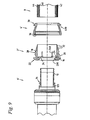
- Fig. 1 shows in a cross-sectional view four workpieces: a fitting 6, a power transmission element 2, a sliding sleeve 4 and a pipe. 8
- the fitting 6 has a profile body having a supporting body 10.
- the support body 10 extends in this example of a base body 12.
- the fitting 6 also has at the transition point from the base body 12 to the support body 10 facing in the axial direction abutment surface 14.
- the profile consists in this particular example of seven annular circumferential grooves, which are delimited by six interposed, annular peripheral dividers.
- the inner peripheral surface of the support body 10 is formed substantially cylindrical, but the support body wall is slightly beveled radially outwardly at the distal end of the base body 12 of the support body 10 in order to make the cross-sectional transition continuous.
- the fitting 6 in Fig. 1 A force transmission element 2 is arranged upstream.
- the force transmission element 2 has a flange section 16 facing the fitting 6 and a transmission section 18.
- a radially inwardly extending contact element 20 On the inner peripheral surface of the flange portion 16 in this embodiment, a radially inwardly extending contact element 20.
- the force transmission element 2 is on the outer peripheral surface of the Flange portion 16 on the front side beyond a chamfer 22 arranged, which can serve as an interaction surface with a pressing tool (not shown).
- the flange portion 16 at its radially inwardly extending region on an axially facing abutment surface 24, on which the end face of a pipe 8 can come into abutment.
- the inner peripheral surface of the flange portion 16 may be formed as a polygon (not shown). In this way, in the interaction with the inner circumferential surface of the flange portion 16 opposite outer peripheral surface of the Fittinggrund stressess 12, on which the force transmission element 2 is to be positioned, an additional safeguard against unwanted rotational movements of the force transmission element 2 relative to the fitting 6 can be achieved.
- the transmission section 18 of the force transmission element 2 has a wall thickness which tapers from the flange section 16 to the wall section which tapers at least in sections, as far as the flange section 16.
- the taper so the wall thickness decrease though by form elements such as in this example at the proximal end of the flange portion 16 of the transfer section 18 locking recess 26 which is annularly circulating, and in this example between the locking recess 26 and the annular end of the retaining portion 28 arranged distal to the flange portion 16 is modified, but tends to remain.
- the taper or wall thickness decrease can thus by an imaginary line (not shown), which by the most radially outwardly portions of the transfer section 18th runs, for example in the manner of an envelope, are represented.
- the wall thickness decrease takes place at least in sections by forming a conical segment surface, which is inclined at an angle of about 15 ° to the central axis 30 of the power transmission element 2.
- three recesses 32 for reducing the contact area are arranged between the holding recess 28 and the distal end.
- the recesses 32 in this example take the form of annular circumferential grooves, but may for example also be formed as a corrugation.
- two openings 34 are arranged in this example, which have a substantially extending in the circumferential direction extent.
- the openings 34 allow an installer to visually inspect the position of the workpieces 2, 4, 6, 8 before and optionally after the pressing operation.
- the openings 34 may of course also have a different shape or be arranged at a different location.
- the number of openings 34 can basically be chosen freely.
- a formation of the inner peripheral surface of the transfer section 18 as a polygon may be provided.
- Fig. 1 a sliding sleeve 4, whose first end has a certain thickness in cross-section, that is, in the cross-sectional view, and whose second end is tapered in cross-section with respect to the first end.
- the outer diameter of the sliding sleeve 4 is at least partially constant over the outer peripheral surface in the axial direction. This means in particular that shape features with a small spatial dimension can be provided, which modify the constancy of the outer diameter. In this particular example, a modification is made in that the tapered end of the sliding sleeve 4 is slightly angled radially outward. But it is also possible to form the sliding sleeve 4 with a constant over the entire axial extent of the sliding sleeve 4 outer diameter.
- a radially inwardly extending latching projection 36 is disposed on the inner peripheral surface of the tapered end, which is annularly circumferential in this example.
- the inner circumferential surface of the sliding sleeve 4 has at least sections of hollow cone segment shape.
- a chamfer 38 is arranged at the non-tapered end, on which a pressing tool (not shown) can begin.
- the installation shown is a composite pipe 8, which comprises three layers 40, 42, 44.
- the inner layer 40 may be made of a cross-linked polyethylene (PEX), the middle layer 42 of a metal such as aluminum, and the outer layer 44 of a particular mechanical stresses resistant or aesthetic Consider sufficient plastic.
- PEX cross-linked polyethylene
- shown composite tube 8 is to be understood only as an example.
- the in Fig. 1 shown installation also comprise a single-layer pipe, for example made of a plastic or a metal or metal material.
- the cross section of the tube 8 is not limited in principle.
- the relevant diameters of the workpieces 2, 4, 6, 8, ie the outer diameter of the support body 10 of the fitting 6 and the inner diameter of the tube 8 or the outer diameter of the tube 8 and the inner diameter of the transfer section 18 of the force transmission element 2 suitable for each other or adapted to each other.
- Fig. 2 shown installation differs from the one in Fig. 1 illustrated in that the force transmission element 2 is fitted onto the fitting 6 and that the fitting 6 engages in the force transmission element 2.
- the flange portion 16 is fixed in this example via a press fit, so a frictional engagement with the fitting body 12 and thereby inhibits an axial movement of the power transmission element 2 and the fitting 6 to each other.
- the facing in the axial direction abutting surface 14 of the fitting 6 is in this example with the arranged on the flange portion 16 contact element 20 in abutment.
- the fitting base body 12 is encompassed essentially by the flange section 16 and the support body 10 essentially by the transmission section 18, with the distal end of the support body 10 protruding from the force transmission element 2 on the transmission section side.
- this embodiment is not mandatory. It is also conceivable that the distal end of the support body 10 and the distal end of the transfer section 18 come to lie approximately in the same perpendicular plane to the central axis 30, or that the distal end of the transfer section 18 even projects beyond the support body 10. So it can be chosen different configurations.
- FIG. 3 The inventive arrangement shown differs from that in Fig. 2 represented in that the sliding sleeve 4 is placed on the transmission section side on the power transmission element 2.
- the arranged on the tapered end of the sliding sleeve 4 locking projection 36 engages in the arranged on the outer peripheral surface of the transfer section 18 holding recess 28 so that in an intermediate position - before the actual pressing operations are initiated - a movement of the sliding sleeve 4 is prevented by the force transmission element 2 down
- the other sections of the inner circumferential surface of the sliding sleeve 4 and the portion of the transfer section 18 located between the holding recess 28 and the distal end are preferably adapted to one another and are at least partially in frictional engagement, with the exception of the depressing depressions 32.
- Fig. 3 thus shows an inventive arrangement for producing a non-detachable workpiece connection, as an installer can purchase commercially, and which only has to be supplemented by a pipe to be compressed 8 in order to make the grouting can.
- Fig. 4 shows those from the Fig. 1 to 3 known installation, in which the tube 8 is inserted into the cavity between the support body 10 of the fitting 6 and the transmission portion 18 of the power transmission element 2. The end face of the tube 8 is pushed up to the stop on the flange portion 16 or arranged on the flange portion 16 contact element 20. By arranged on the transfer section 18 openings 34 (not visible), the installer in the in Fig. 4 shown installation the proper position of the workpieces 2, 4, 6, 8 to each other.
- Fig. 5a The result of the axial pressing process is in Fig. 5a shown.
- the sliding sleeve 4 is moved over the transfer section 18 in the axial direction toward the flange section 16. Due to the inclination of the portion of the inner circumferential surface of the sliding sleeve 4 and the corresponding portions of the outer peripheral surface of the transfer section 18, the dynamics of the pressing movement exerted in the axial direction in this particular embodiment is at least partially deflected into radially inwardly acting pressing forces.
- the transfer section 18 transmits the pressing forces to the tube 8, which is radially inwardly deformed so that the grooves separated by the separating webs on the support body 10 of the Fittings 6 record the displaced material of the tube 8, and thus a positive and positive connection can arise, which ensures the tightness of the permanent workpiece connection.
- a portion of the locking projection 36 may be in contact with a wall of the locking recess 26 so that an axial movement of the sliding sleeve 4 after the axial pressing process is inhibited by the power transmission element 2 down.
- the tapered end of the sliding sleeve 4 protrudes slightly beyond the plane defined by the outer peripheral surface of the flange portion 16 radially outward slightly after the axial pressing operation and thus provides a pressing tool 48 a favorable starting point for a radially inward pressing movement (arrow 50).
- the axial pressing process followed by a radially inward pressing operation whereby a portion of the sliding sleeve 4, in this example, the tapered end of the sliding sleeve 4, is arranged on the inner peripheral surface of the locking projection 36, is formed in the locking recess 26 and thus a stable locking of the Sliding sleeve 4 causes the force transmission element 2.
- This can counteract the fact that the sliding sleeve 4 of the force transmission element 2, for example due to triggered by temperature changes material expansions or contractions again dissolves, which could have leaks result.
- Fig. 6a shows again the four workpieces 2, 4, 6, 8, after both the axial and the radially inward pressing process completed and the permanent workpiece connection are made with it.
- the angled end of the sliding sleeve 4 during the radially inward pressing operation with the outer peripheral surface of the flange portion 16 is formed in a substantially aligned orientation. In this way, the permanent workpiece connection can be made very compact.
- Fig. 7 shows in a cross-sectional view of four workpieces: a fitting 6, a power transmission element 2 ', a sliding sleeve 4 and a pipe 8. Die das Opera aus Fig. 1 corresponding parts are identified by the same reference numerals.
- the force transmission element 2 ' has a means 28' for temporarily fixing a sliding sleeve.
- the means 28 ' can be designed, for example, as a surface suitable for frictional engagement with the sliding sleeve 4, as an adhesive surface, as a thread or as a depression suitable for form and / or frictional engagement.
- the sliding sleeve in the region of the locking projection 36 may be configured with a corresponding mating thread.
- Fig. 8 shows an inventive arrangement for producing a non-detachable workpiece connection of the in Fig. 7 shown components, such as an installer can purchase commercially, and which only has to be supplemented by a pipe to be compressed 8 in order to make the compression can.
- power transmission element 2 ' may alternatively have no means 28' for temporarily fixing a sliding sleeve.
Landscapes
- Engineering & Computer Science (AREA)
- General Engineering & Computer Science (AREA)
- Mechanical Engineering (AREA)
- Mutual Connection Of Rods And Tubes (AREA)
- Automatic Assembly (AREA)
- Insertion Pins And Rivets (AREA)
Description
Die Erfindung offenbart ein Kraftübertragungselement für unlösbare Werkstückverbindungen, mit einem Flanschabschnitt und mit einem Übertragungsabschnitt, wobei der Übertragungsabschnitt eine im Wesentlichen zylinderförmige Innenumfangsfläche aufweist und wobei die Wanddicke des Übertragungsabschnitts sich von dem dem Flanschabschnitt proximalen Ende bis zu dem dem Flanschabschnitt distalen Ende wenigsten abschnittsweise verjüngt. Die Erfindung offenbart weiterhin eine Gleithülse für unlösbare Werkstückverbindungen, mit einem ersten Ende, welches im Querschnitt eine bestimmte Dicke aufweist, und mit einem zweiten Ende, welches gegenüber dem ersten Ende im Querschnitt verjüngt ist, wobei der Außendurchmesser über die Außenumfangsfläche in axialer Richtung wenigstens abschnittsweise konstant ist. Die Erfindung betrifft eine Anordnung aus einem Fitting, dem Kraftübertragungselement und der Gleithülse sowie ein Verfahren zur Herstellung einer unlösbaren Werkstückverbindung zwischen einem Fitting, einem Rohr, einem Kraftübertragungselement und einer Gleithülse.The invention discloses a power transmission element for permanent work piece connections, comprising a flange portion and a transmission portion, wherein the transmission portion has a substantially cylindrical inner peripheral surface and wherein the wall thickness of the transmission portion tapers at least in sections from the flange proximal end to the flange distal end. The invention further discloses a sliding sleeve for permanent workpiece connections, with a first end, which has a certain thickness in cross section, and with a second end, which is tapered in cross section with respect to the first end, wherein the outer diameter over the outer peripheral surface in the axial direction at least in sections is constant. The invention relates to an assembly of a fitting, the power transmission element and the sliding sleeve and a method for producing a permanent workpiece connection between a fitting, a pipe, a force transmission element and a sliding sleeve.
Eine Anordnung mit einem Kraftübertragungselement und mit einer Gleithülse der eingangs genannten Art sind beispielsweise aus der
Eine ähnliche Rohrpresskupplung mit einer Quetschhülse, einer über die Quetschhülse schiebbare Presshülse mit einer radial umlaufenden Presswulst und einem Fittingstützkörper wird in der Druckschrift
Die Patentschrift
Die Neigewinkel der Flächen, mit welchen das Kraftübertragungselement und der Pressring während des Pressvorgangs interagieren, bezüglich der Mittelachse sind dabei gering, um einen möglichst großen Anteil der axialen Dynamik in eine radial einwärtige Pressbewegung umsetzen zu können. Die geringen Neigewinkel haben jedoch eine weitgreifende axiale Bewegung des Pressrings zur Folge. Dementsprechend müssen die Presswerkzeuge als auch die zu verpressenden Werkstücke wie beispielsweise das Fitting weitgreifende Abmessungen aufweisen. Zwar ist es grundsätzlich möglich, die Interaktionsflächen des Pressrings und des Kraftübertragungselements mit höheren Neigewinkeln zur Mittelachse zu versehen. Allerdings sind dadurch die Selbsthaltekräfte zwischen dem Kraftübertragungselement und dem Pressring nach dem Pressvorgang verringert, so dass sich diese, insbesondere unter dem Einfluss von Temperaturwechseln und der damit verbundenen Materialausdehnung bzw. - kontraktion leichter lösen und somit die Gefahr des Auftretens von Undichtigkeiten erhöhen können.The tilt angle of the surfaces with which the force transmission element and the pressure ring interact during the pressing process, with respect to the central axis are small in order to implement as large a proportion of the axial dynamics in a radially inward pressing movement can. The low tilt angle, however, have a far-reaching axial movement of the press ring result. Accordingly, the pressing tools as well as the workpieces to be pressed, such as the fitting must have far-reaching dimensions. Although it is basically possible to provide the interaction surfaces of the compression ring and the power transmission element with higher tilt angles to the central axis. However, this reduces the self-holding forces between the force transmission element and the pressing ring after the pressing process, so that these, in particular under the influence of temperature changes and the associated material expansion or - contraction easier to solve and thus increase the risk of the occurrence of leaks.
Der vorliegenden Erfindung liegt daher das technische Problem zu Grunde, eine Anordnung sowie ein Verfahren zur Herstellung einer unlösbaren Werkstückverbindung anzugeben, mit welchen eine betriebssichere unlösbare Werkstückverbindung trotz geringerer Abmessungen der Werkstücke erreicht werden kann.The present invention is therefore the technical problem of specifying an arrangement and a method for producing a non-detachable workpiece connection, with which a reliable permanent non-detachable workpiece connection can be achieved despite lower dimensions of the workpieces.
Gemäß einer ersten Lehre der vorliegenden Erfindung wird das technische Problem durch eine Anordnung gemäß dem Patentanspruch 1 unter anderem mit einem Kraftübertragungselement gelöst, wobei das dem Flanschabschnitt proximale Ende des Übertragungsabschnitts an der Außenumfangsfläche wenigstens eine Rastvertiefung aufweist.According to a first teaching of the present invention, the technical problem is solved by an arrangement according to claim 1, inter alia, with a force transmission element, wherein the flange portion proximal end of the transmission section on the outer peripheral surface has at least one detent recess.
Auf diese Weise ist es möglich, eine Außenumfangsfläche des Übertragungsabschnitts mit gegenüber der Mittelachse erhöhtem Neigewinkel auszubilden, so dass eine Verringerung sowohl der geometrischen Abmessungen des Kraftübertragungselements als auch des axialen Verpresswegs umsetzbar ist.In this way, it is possible to form an outer circumferential surface of the transfer section with an angle of incline increased relative to the central axis, so that a reduction of both the geometric dimensions of the force transmission element and the axial Verpresswegs is feasible.
In einer Ausgestaltung des Kraftübertragungselements ist an der Außenumfangsfläche zwischen der Rastvertiefung und dem distalen Ende des Übertragungsabschnitts wenigstens ein Mittel zum temporären Fixieren einer Gleithülse angeordnet. Die Mittel zum temporären Fixieren einer Gleithülse können beispielsweise reibschlüssig, stoffschlüssig, beispielsweise als Kleber, oder formschlüssig, beispielsweise als Gewinde oder Vertiefung, ausgebildet sein. Diese Ausgestaltung ist vorteilhaft zur Ausbildung einer Außenumfangsfläche des Übertragungsabschnitts mit gegenüber der Mittelachse weiter erhöhtem Neigewinkel. Denn durch das Vorsehen eines Mittel zum temporären Fixieren einer Gleithülse und einer Rastvertiefung an dem Übertragungsabschnitt werden entlang der axialen Erstreckung des Übertragungsabschnitts wenigstens zwei definierte Positionen geschaffen, an denen eine Gleithülse, welche zur Ausübung der für die Verpressung erforderlichen Kräfte verwendet wird, gehalten werden kann. Bei entsprechender Ausgestaltung kann - in einem Verfahren zum Herstellen einer unlösbaren Werkstückverbindung zwischen einem Fitting, einem Rohr, dem Kraftübertragungselement und der Gleithülse - die Gleithülse in einem ersten Schritt des Verfahrens, bevor die eigentliche Verpressung erfolgt, an dem Kraftübertragungselement positioniert werden, wobei das Mittel zum temporären Fixieren einer Gleithülse eine axiale Bewegung der Gleithülse von dem Kraftübertragungselement herunter hemmt.In one embodiment of the force transmission element is on the outer peripheral surface between the locking recess and the at least one means for temporarily fixing a sliding sleeve arranged distal end of the transfer section. The means for temporarily fixing a sliding sleeve can be formed, for example, by frictional engagement, materially bonded, for example as an adhesive, or in a form-fitting manner, for example as a thread or depression. This embodiment is advantageous for forming an outer peripheral surface of the transfer section with respect to the central axis further increased tilt angle. Because by the provision of a means for temporarily fixing a sliding sleeve and a detent recess on the transmission section along the axial extent of the transmission section at least two defined positions created at which a sliding sleeve, which is used to exercise the forces required for the compression, can be maintained , In a corresponding embodiment can - in a method for producing a permanent workpiece connection between a fitting, a pipe, the power transmission element and the sliding sleeve - the sliding sleeve in a first step of the method, before the actual compression takes place, be positioned on the force transmission element, wherein the means for temporarily fixing a sliding sleeve inhibits an axial movement of the sliding sleeve of the power transmission element down.
Die an dem Übertragungsabschnitt des Kraftübertragungselements angeordnete Rastvertiefung wiederum kann vorteilhaft verwendet werden, um die Gleithülse nach erfolgter axialer Verpressung mittels eines radial einwärtigen Pressvorgangs an dem Kraftübertragungselement zu fixieren, beispielsweise indem Abschnitte der Gleithülse in die Rastvertiefung eingeformt werden. Somit werden nach dem Abschließen der Pressvorgänge Bewegungen der Gleithülse von dem Kraftübertragungselement herunter effektiv gehemmt, selbst wenn das Material der Werkstücke auf Grund von Temperaturschwankungen einer Ausdehnung bzw. Kontraktion unterworfen sein sollte. Die Gefahr von Undichtigkeiten wird entsprechend reduziert. Somit kann eine stabilere und dauerhaftere Werkstückverbindung geschaffen werden, auch wenn die Neigewinkel höher als sonst üblich und sowohl die äußeren Abmessungen der Werkstücke, insbesondere des Kraftübertragungselements als auch die axialen Verpresswege verringert sind.The latching depression arranged on the transmission section of the force transmission element can in turn be advantageously used to fix the sliding sleeve to the force transmission element after axial compression by means of a radially inward pressing process, for example by forming sections of the sliding sleeve in the latching recess. Thus, after the Completing the pressing operations effectively inhibits movements of the sliding sleeve from the power transmission member even if the material of the workpieces should be subject to expansion or contraction due to temperature variations. The risk of leaks is reduced accordingly. Thus, a more stable and durable workpiece connection can be created, even if the tilt angle is higher than usual and both the outer dimensions of the workpieces, in particular of the power transmission element and the axial Verpresswege are reduced.
Der Flanschabschnitt bietet vorzugsweise eine Anlagefläche für eine Stoßfläche der Gleithülse vor und/oder nach den Pressvorgängen und begrenzt demnach die axiale Beweglichkeit der Gleithülse in wenigstens einer Richtung. Der Übertragungsabschnitt wiederum ermöglicht es, die Dynamik der axial ausgeführten Bewegung des Presswerkzeugs zumindest teilweise in eine radial einwärtige Bewegung umzusetzen und somit die Kräfte aufzubringen, welche erforderlich sind, um den von dem Kraftübertragungselement umgriffenen Rohrabschnitt auf einen Stützkörper eines Fittings aufzuformen bzw. in das gegebenenfalls vorhandene Profil des Stützkörpers des Fittings einzuformen, wodurch die kraftgegebenenfalls auch formschlüssige Werkstückverbindung zwischen den Werkstücken, insbesondere dem Rohr und dem Fitting geschaffen wird.The flange portion preferably provides a contact surface for an abutting surface of the sliding sleeve before and / or after the pressing operations and therefore limits the axial mobility of the sliding sleeve in at least one direction. The transmission section in turn makes it possible to at least partially convert the dynamics of the axially executed movement of the pressing tool into a radially inward movement and thus to apply the forces which are required to mold the tube section encompassed by the force transmission element onto a supporting body of a fitting or into the optionally Forming existing profile of the support body of the fitting, whereby the force if necessary, form-fitting workpiece connection between the workpieces, in particular the pipe and the fitting is created.
Die Innenumfangsfläche des Übertragungsabschnitts ist im Wesentlichen zylinderförmig ausgebildet. Dies ist so zu verstehen, dass ein für eine unlösbare Werkstückverbindung vorgesehenes Rohr übertragungsabschnittseitig in das Kraftübertragungselement, gegebenenfalls reibschlüssig einführbar sein soll. Da viele Rohre einen kreisringförmigen Außenquerschnitt aufweisen, kann daher eine entsprechend angepasste kreiszylinderförmige Ausgestaltung der Innenumfangsfläche des Übertragungsabschnitts zweckmäßig sein. Allerdings kann das Kraftübertragungselement auch für andere Rohraußenquerschnitte, beispielsweise ellipsenförmige oder prismenförmige Querschnitte geeignet ausgestaltet werden. Der Begriff zylinderförmig ist also sehr weit zu verstehen. Insbesondere kann die im Wesentlichen zylinderförmige Innenumfangsfläche durch bauliche Merkmale, welche den zylindrischen Charakter der Fläche, beispielsweise auf Grund ihrer kleinen Dimensionen nur unwesentlich ändern, modifiziert sein.The inner circumferential surface of the transfer section is substantially cylindrical. This is to be understood as meaning that a pipe provided for an unsolvable work piece connection has a transfer section side into the pipe Force transmission element, if necessary, to be frictionally inserted. Since many tubes have an annular outer cross section, therefore, a suitably adapted circular cylindrical configuration of the inner peripheral surface of the transfer section may be appropriate. However, the power transmission element can also be configured suitably for other pipe outer cross sections, for example elliptical or prismatic cross sections. The term cylindrical is therefore very broad. In particular, the substantially cylindrical inner peripheral surface may be modified by constructional features which only insignificantly change the cylindrical character of the surface, for example due to its small dimensions.
Durch die wenigstens abschnittsweise Verjüngung der Wanddicke des Übertragungsabschnitts wird vorteilhafter Weise eine Außenumfangsfläche geschaffen, welche in der Wechselwirkung mit einer geeigneten, zum Zwecke der Verpressung betätigten Gleithülse während des axialen Pressvorgangs eine gleichmäßigere Kraftausübung ermöglicht. Auf diese Weise können die Dichtheit einer unlösbaren Werkstückverbindung beeinträchtigende Unregelmäßigkeiten im Pressergebnis zwischen dem Stützkörper eines Fittings und einem Rohr vermieden werden. Maßnahmen in Form zusätzlicher Dichtelemente, wie sie nach dem Stand der Technik häufig zwischen dem Stützkörper und dem Rohrinneren angeordnet werden, sind dadurch ebenfalls vermeidbar. Abschnittsweise Verjüngung bedeutet insbesondere, dass an der Außenumfangsfläche des Übertragungsabschnitts noch weitere Formmerkmale angeordnet werden können, beispielsweise weitere Vertiefungen zwischen dem Mittel zum temporären Fixieren einer Gleithülse und dem distalen Ende des Übertragungsabschnitts, welche den Verlauf der Verjüngung, also der Wandstärkenreduzierung, zwar modifizieren, aber in der Tendenz bestehen lassen.By the at least partially tapering of the wall thickness of the transfer section, an outer peripheral surface is advantageously created, which allows in the interaction with a suitable, operated for the purpose of pressing sliding sleeve during the axial pressing operation a more uniform application of force. In this way, the tightness of an insoluble workpiece connection affecting irregularities in the Pressergebnis between the support body of a fitting and a pipe can be avoided. Measures in the form of additional sealing elements, as they are often arranged according to the prior art between the support body and the tube interior, are thereby also avoidable. Sectional taper means in particular that on the outer peripheral surface of the transfer section even more shape features can be arranged, for example, further recesses between the means for temporary fixing a sliding sleeve and the distal end of the transfer section, which modify the course of the taper, so the wall thickness reduction, but tend to persist.
Die Rastvertiefung kann ringförmig umlaufend ausgebildet sein, oder mehrere Rastvertiefungen können auf einer ringförmig umlaufenden Trajektorie, insbesondere in regelmäßigen Abständen angeordnet sein. Durch die bauliche Ausgestaltung der Rastvertiefung als ringförmig umlaufende Vertiefung kann insbesondere ein bezüglich dieses Merkmals rotationssymmetrisches Kraftübertragungselement zur Verfügung gestellt werden, welches vorteilhaft mit anderen rotationssymmetrischen Werkstücken, beispielsweise Gleithülsen interagieren kann. Darüber hinaus wird die Haltbarkeit einer hergestellten Werkstückverbindung über den gesamten Umfang der Werkstücke sichergestellt. Es ist aber auch möglich, statt einer ringförmig umlaufenden Rastvertiefung mehrere einzelne Rastvertiefungen, beispielsweise in Form von Kugelsegmenten mit entsprechenden Hohlkalottenflächen, vorzusehen, welche gegebenenfalls auf einer ringförmig um den Übertragungsabschnitt umlaufenden Linie angeordnet sind. Dies kann fertigungstechnisch vorteilhaft sein, wenn bei der Herstellung des Kraftübertragungselements wenig Material des Werkstücks ausgenommen werden soll.The detent recess may be formed annularly circumferential, or a plurality of detent recesses may be arranged on an annular circulating trajectory, in particular at regular intervals. Due to the structural design of the detent recess as an annular circumferential recess in particular with respect to this feature rotationally symmetrical force transmission element can be provided, which can advantageously interact with other rotationally symmetrical workpieces, such as sliding sleeves. In addition, the durability of a manufactured workpiece connection over the entire circumference of the workpieces is ensured. But it is also possible, instead of an annular circumferential detent recess a plurality of individual locking recesses, for example in the form of spherical segments with corresponding Hohlkalottenflächen, provide, which are optionally arranged on an annular circulating around the transfer section line. This can be advantageous in terms of production if little material of the workpiece is to be excluded in the production of the force transmission element.
In einer weiteren Ausgestaltung des Kraftübertragungselements ist an der Außenumfangsfläche zwischen der Rastvertiefung und dem distalen Ende des Übertragungsabschnitts wenigstens eine Haltevertiefung angeordnet. Diese Ausgestaltung des Mittels zum temporären Fixieren einer Gleithülse als Haltevertiefung ist zuverlässig und besonders einfach herzustellen. Um ein sicheres Einrasten der Gleithülse in die Haltevertiefung zu gewährleisten, kann an der Gleithülse ein entsprechendes Gegenstück vorgesehen sein, dass zur Fixierung der Gleithülse mit der Haltevertiefung in Eingriff vorliegt.In a further embodiment of the force transmission element, at least one holding recess is arranged on the outer peripheral surface between the latching recess and the distal end of the transmission section. This embodiment of the means for temporarily fixing a sliding sleeve as a holding recess is reliable and very easy to manufacture. In order to ensure a secure engagement of the sliding sleeve in the retaining recess, a corresponding counterpart may be provided on the sliding sleeve that is present for fixing the sliding sleeve with the retaining recess.
Die Haltevertiefung kann ringförmig umlaufend ausgebildet sein, oder mehrere Haltevertiefungen können auf einer ringförmig umlaufenden Trajektorie, insbesondere in regelmäßigen Abständen angeordnet sein. Für die Haltevertiefungen gelten die zuvor zu den Rastvertiefungen gemachten Ausführungen in analoger Weise.The retaining recess may be formed annularly circumferential, or a plurality of retaining recesses may be arranged on an annular circulating trajectory, in particular at regular intervals. For the holding wells, the statements made previously to the locking recesses apply in an analogous manner.
In einer weiteren Ausgestaltung des Kraftübertragungselements kann an der Außenumfangsfläche des Übertragungsabschnitts wenigstens eine Vertiefung zur Verringerung der Kontaktfläche vorgesehen sein. Derartige Vertiefungen können beispielsweise in der Form von Rillen oder auch als Riffelung ausgebildet werden. Der Widerstand, den das Kraftübertragungselement und die Gleithülse einer einander gegenläufigen axialen Verpressbewegung entgegen setzen, ist im Wesentlichen von der Kontaktfläche bzw. den Kontaktflächen zwischen der Außenumfangsfläche des Übertragungsabschnitts und der Innenumfangsfläche der Gleithülse abhängig. Durch die Vertiefungen zur Verringerung der Kontaktflächen wird dieser Widerstand reduziert, weshalb das Aufführen der Gleithülse auf den Übertragungsabschnitt während der axialen Pressbewegung und der axiale Pressvorgang als solches somit erleichtert werden.In a further embodiment of the force transmission element may be provided on the outer peripheral surface of the transfer section at least one recess for reducing the contact surface. Such depressions can be formed, for example, in the form of grooves or as corrugations. The resistance which the force transmission element and the sliding sleeve oppose to an opposing axial pressing movement is essentially dependent on the contact surface or surfaces between the outer peripheral surface of the transmission section and the inner circumferential surface of the sliding sleeve. By the recesses for reducing the contact surfaces of this resistance is reduced, so the performance of the sliding sleeve on the transfer section during the axial pressing movement and the axial pressing operation as such are thus facilitated.
Es ist möglich, die Außenumfangsfläche des Übertragungsabschnitts wenigstens abschnittsweise kegelsegmentförmig auszubilden, wobei der Neigungswinkel relativ zur Mittelachse insbesondere 15° bis 75°, vorzugsweise 25° bis 65°, speziell 35° bis 55° beträgt. Durch die Wahl eines relativ hohen Winkels können sowohl die äußeren Abmessungen des Kraftübertragungselements als auch der axiale Verpressweg verringert werden.It is possible that the outer peripheral surface of the transfer section at least in sections form cone segment-shaped, wherein the inclination angle relative to the central axis in particular 15 ° to 75 °, preferably 25 ° to 65 °, especially 35 ° to 55 °. By choosing a relatively high angle, both the outer dimensions of the power transmission element and the axial Verpressweg can be reduced.
Die Außenumfangsfläche des Übertragungsabschnitts kann zumindest abschnittsweise gleitfördernd ausgebildet sein. Auf diese Weise kann der Pressvorgang erleichtert werden. Die Außenumfangsfläche gleitfördernd auszubilden, kann auf unterschiedliche Weise geschehen. Es ist möglich, die entsprechenden Abschnitte des Übertragungsabschnitts zweiteilig auszubilden, und die Flächen aus einem Material wie Polytetrafluorethylen oder ähnlichem zu fertigen. Es ist allerdings auch möglich, das Gleitvermögen mittels einer gleitfördernden Beschichtung der Flächen, beispielsweise mit einer Gleitlackbeschichtung zu erhöhen.The outer peripheral surface of the transfer section may be designed to promote sliding at least in sections. In this way, the pressing process can be facilitated. The outer peripheral surface can be designed to promote sliding, can be done in different ways. It is possible to form the respective sections of the transfer section in two parts, and to manufacture the surfaces of a material such as polytetrafluoroethylene or the like. However, it is also possible to increase the slipperiness by means of a sliding-promoting coating of the surfaces, for example with a bonded coating.
Es ist möglich, dass der Flanschabschnitt an seiner Innenumfangsfläche ein radial einwärts ausgreifendes Anlageelement aufweist. Dies ist insbesondere günstig, wenn die Innenumfangsfläche des Flanschabschnitts, insbesondere deren Form bzw. deren Durchmesser in einer für eine Presspassung mit dem Grundkörper eines Fittings geeigneten Weise ausgestaltet ist. Damit lässt sich eine reibschlüssige Passung des Kraftübertragungselements auf einem Fitting erzielen, welche gegebenenfalls in der Lage ist, das Kraftübertragungselement und das Fitting auch bei während des Pressvorgangs ausgeübten Kräften in einer weitgehend festen Position zueinander zu halten.It is possible that the flange portion has on its inner peripheral surface a radially inwardly extending contact element. This is particularly favorable when the inner peripheral surface of the flange portion, in particular its shape or its diameter is configured in a suitable manner for a press fit with the main body of a fitting manner. This makes it possible to achieve a frictional fit of the force transmission element on a fitting, which may possibly be able to hold the force transmission element and the fitting in a largely fixed position relative to one another even during forces exerted during the pressing process.
Gemäß der ersten Lehre der vorliegenden Erfindung weist die Anordnung unter anderem auch eine Gleithülse auf wobei an der Innenumfangsfläche des verjüngten Endes wenigstens ein radial einwärts ausgreifender Rastvorsprung angeordnet ist.According to the first teaching of the present invention, the arrangement also has, among other things, a sliding sleeve, wherein at least one radially inwardly extending latching projection is arranged on the inner circumferential surface of the tapered end.
Mittels des radial einwärts ausgreifenden Rastvorsprungs an der Innenumfangsfläche der Gleithülse kann die Gleithülse stabil an dem Kraftübertragungselement positioniert werden. Beispielsweise steht der Rastvorsprung mit der Haltevertiefung in Eingriff, wenn die Gleithülse vor der Einleitung der Pressvorgänge auf den Übertragungsabschnitt des Kraftübertragungselements aufgeschoben ist, und hemmt damit eine Bewegung der Gleithülse von dem Kraftübertragungselement herunter. Alternativ kann die Gleithülse im Bereich des Rastvorsprungs auch mit dem Kraftübertragungselement reibschlüssig, stoffschlüssig, beispielsweise durch einen Kleber, oder auf eine andere Art formschlüssig, beispielsweise durch ein Gewinde am Rastvorsprung und am Kraftübertragungselement, verbunden sein. Somit kann insbesondere eine stabilere Prozessführung gewährleistet werden. Vorzugsweise besteht die Gleithülse ferner aus einem elastischen Material, so dass das verjüngte Ende der Gleithülse im Zuge des axialen Pressvorgangs elastisch leicht aufgeweitet werden kann, bis eine vorläufige Endposition des Rastvorsprungs gegenüber der Rastvertiefung des Kraftübertragungselements vor dem Einleiten des radial einwärtigen Pressvorgangs erreicht ist. Die zumindest abschnittsweise vorliegende Konstanz des Außendurchmessers der Außenumfangsfläche der Gleithülse kann beispielsweise durch eine leichte radial auswärtige Abwinkelung des verjüngten Endes modifiziert sein. In einer vorzugsweise auf das Kraftübertragungselement angepassten Ausgestaltung trägt die Gleithülse ebenfalls dazu bei, dass sowohl die äußeren Abmessungen der Werkstücke als auch die axialen Verpresswege verringert werden können.By means of the radially inwardly extending latching projection on the inner peripheral surface of the sliding sleeve, the sliding sleeve can be stably positioned on the force transmission element. For example, the locking projection engages with the retaining recess when the sliding sleeve is pushed onto the transmission portion of the power transmission member prior to the initiation of pressing operations, thereby inhibiting movement of the sliding sleeve from the power transmission member. Alternatively, the sliding sleeve in the region of the latching projection may also be frictionally connected to the force transmission element, materially bonded, for example by an adhesive, or in some other way, for example by a thread on the latching projection and on the force transmission element. Thus, in particular a more stable process management can be ensured. Preferably, the sliding sleeve is further made of an elastic material, so that the tapered end of the sliding sleeve in the course of the axial pressing operation can be elastically slightly expanded until a provisional end position of the locking projection against the locking recess of the force transmission element is reached before initiating the radially inward pressing operation. The at least partially present constancy of the outer diameter of the outer circumferential surface of the sliding sleeve can be modified, for example, by a slight radially outward angling of the tapered end. In a preferably adapted to the power transmission element design contributes The sliding sleeve also helps that both the outer dimensions of the workpieces and the axial Verpresswege can be reduced.
In einer Ausgestaltung der Gleithülse ist das verjüngte Ende radial auswärts, insbesondere leicht, beispielsweise unter einem Winkel von 5° bis 10°, insbesondere 6° bis 8° zur Mittelachse, abgewinkelt. Mit dieser Ausgestaltung kann ein sich dem axialen Pressvorgang anschließender radial einwärtiger Pressvorgang erleichtert werden. Denn nach dem axialen Pressvorgang ragt das abgewinkelte Ende vorzugsweise leicht über die von der Außenumfangsfläche des Flanschabschnitts des Kraftübertragungselements definierten Ebene hervor und bietet somit einem Presswerkzeug für die radial einwärtige Verpressung einen günstigeren Ansatzpunkt zu dem die Stabilität der unlösbaren Werkstückverbindung fördernden Einformen des Abschnitts der Gleithülse in das Kraftübertragungselement.In one embodiment of the sliding sleeve, the tapered end is angled radially outwards, in particular slightly, for example at an angle of 5 ° to 10 °, in particular 6 ° to 8 ° to the central axis. With this configuration, a radially inward pressing operation subsequent to the axial pressing process can be facilitated. For after the axial pressing operation, the angled end preferably protrudes slightly beyond the plane defined by the outer peripheral surface of the flange portion of the power transmission element and thus provides a pressing tool for the radially inward pressing a more favorable starting point for forming the portion of the sliding sleeve in the non-detachable workpiece connection the power transmission element.
Analog zu den zuvor gemachten Ausführungen hinsichtlich der Rastvertiefung bzw. der Haltevertiefung kann der Rastvorsprung ringförmig umlaufend ausgebildet sein, oder mehrere Rastvorsprünge können auf einer ringförmig umlaufenden Trajektorie, insbesondere in regelmäßigen Abständen angeordnet sein.Analogous to the statements made above with regard to the detent recess or the retaining recess, the detent projection may be annular, or a plurality of detent projections may be arranged on an annular circulating trajectory, in particular at regular intervals.
Es kann an der Innenumfangsfläche der Gleithülse wenigstens eine Vertiefung zur Verringerung der Kontaktfläche vorgesehen sein.It can be provided on the inner peripheral surface of the sliding sleeve at least one recess for reducing the contact surface.
In einer weiteren vorteilhaften Ausgestaltung der Gleithülse kann die Innenumfangsfläche wenigstens abschnittsweise kegelsegmentförmig ausgebildet sein, wobei der Neigungswinkel relativ zur Mittelachse insbesondere 15° bis 75°, vorzugsweise 25° bis 65°, speziell 35° bis 55° beträgt.In a further advantageous embodiment of the sliding sleeve, the inner peripheral surface at least in sections cone segment-shaped, wherein the inclination angle relative to the central axis in particular 15 ° to 75 °, preferably 25 ° to 65 °, especially 35 ° to 55 °.
Es ist möglich, die Innenumfangsfläche der Gleithülse zumindest abschnittsweise gleitfördernd auszubilden.It is possible to form the inner peripheral surface of the sliding sleeve at least in sections so as to promote sliding.
Hinsichtlich weiterer Vorteile der Ausgestaltungen der Gleithülse wird auf die Ausführungen zu dem Kraftübertragungselement verwiesen.With regard to further advantages of the embodiments of the sliding sleeve, reference is made to the comments on the force transmission element.
Gemäß der ersten Lehre der vorliegenden Erfindung wird das technische Problem also mit einer Anordnung gemäß dem Oberbegriff des Patentanspruchs 1 dadurch gelöst, dass das dem Flanschabschnitt proximale Ende des Übertragungsabschnitts des Kraftübertragungselements an der Außenumfangsfläche wenigstens eine Rastvertiefung aufweist, dass an der Innenumfangsfläche des verjüngten Endes der Gleithülse wenigstens ein radial einwärts ausgreifender Rastvorsprung angeordnet ist und dass das Kraftübertragungselement den Stützkörper und wenigstens teilweise den Grundkörper umgreift.According to the first teaching of the present invention, the technical problem is thus solved with an arrangement according to the preamble of claim 1, characterized in that the flange portion proximal end of the transmission portion of the force transmission element on the outer peripheral surface has at least one latching recess that on the inner peripheral surface of the tapered end of the Sliding sleeve is arranged at least one radially inwardly extending latching projection and that the force transmission element engages around the support body and at least partially the base body.
Durch die erfindungsgemäße Anordnung kann ein System aus Werkstücken geschaffen werden, welches für einen Verwender im Handel erhältlich ist. Der Verwender hat also lediglich darauf zu achten, dass die Form des Außenquerschnitts und/oder der Außendurchmesser der von ihm zu verpressenden Rohre zu den jeweiligen Abmessungen des Fittings, beispielsweise des Stützkörpers bzw. des Kraftübertragungselements, beispielsweise des Übertragungsabschnitts passend sind. Der Planungsaufwand ist damit reduzierbar.The inventive arrangement, a system of workpieces can be created, which is available for a user in the trade. The user therefore merely has to make sure that the shape of the outer cross section and / or the outer diameter of the pipes to be pressed by him to the respective dimensions of the fitting, for example, the support body or the force transmission element, for example, the transmission section are suitable. The planning effort is thus reduced.
In einer vorteilhaften Ausgestaltung der Anordnung ist an der Außenumfangsfläche zwischen der Rastvertiefung und dem distalen Ende des Übertragungsabschnittes wenigstens ein Mittel zum temporären Fixieren einer Gleithülse angeordnet, die Gleithülse mit dem verjüngten Ende auf den Übertragungsabschnitt so weit aufgeschoben, dass die Gleithülse mit dem Mittel zum temporären Fixieren einer Gleithülse in Anlage liegt und die Gleithülse durch das Mittel zum temporären Fixieren einer Gleithülse am Übertragungsabschnitt temporär fixiert ist. Die temporäre Fixierung der Gleithülse am Übertragungsabschnitt bewirkt, dass einer Bewegung der Gleithülse von dem Kraftübertragungselement herunter vorgebeugt wird.In an advantageous embodiment of the arrangement, at least one means for temporarily fixing a sliding sleeve is arranged on the outer circumferential surface between the latching recess and the distal end of the transmission section, the sliding sleeve with the tapered end pushed onto the transmission section so far that the sliding sleeve with the means for temporary Fixing a sliding sleeve is in abutment and the sliding sleeve is temporarily fixed by the means for temporarily fixing a sliding sleeve on the transfer section. The temporary fixation of the sliding sleeve on the transmission section causes a movement of the sliding sleeve is prevented by the force transmission element down.
In einer weiteren vorteilhaften Ausgestaltung der Anordnung ist an der Außenumfangsfläche zwischen der Rastvertiefung und dem distalen Ende des Übertragungsabschnitts wenigstens eine Haltevertiefung angeordnet und die Gleithülse mit dem verjüngten Ende auf den Übertragungsabschnitt so weit aufgeschoben, dass der Rastvorsprung in die Haltevertiefung eingreift. Die Ausgestaltung des Mittels zum temporären Fixieren einer Gleithülse als Haltevertiefung ist zuverlässig und besonders einfach herzustellen.In a further advantageous embodiment of the arrangement, at least one retaining recess is arranged on the outer peripheral surface between the latching recess and the distal end of the transmission section and the sliding sleeve with the tapered end pushed onto the transmission section so far that the latching projection engages in the retaining recess. The design of the means for temporarily fixing a sliding sleeve as a holding recess is reliable and very easy to manufacture.
In einer vorteilhaften Ausgestaltung der Anordnung liegen die Innenumfangsfläche der Gleithülse und die Außenumfangsfläche des Übertragungsabschnitts vorzugsweise wenigstens teilweise in reibschlüssiger Anlage. Damit kann einer Bewegung der Gleithülse aus der vor den Pressvorgängen eingenommenen, definierten Zwischenposition heraus und von dem Übertragungsabschnitt des Kraftübertragungselements herunter entgegen gewirkt werden. Die Prozesssicherheit kann damit verbessert werden.In an advantageous embodiment of the arrangement, the inner peripheral surface of the sliding sleeve and the outer peripheral surface of the transfer section are preferably at least partially frictionally engaged. This can be a movement of the sliding sleeve from the occupied before the pressing operations, defined intermediate position and down from the transmission portion of the power transmission element counteracted. Process reliability can thus be improved.
Der Flanschabschnitt kann an dem Grundkörper fixiert sein, wobei insbesondere ein Anlageelement des Flanschabschnitts an einer in axialer Richtung gewandten Stoßfläche des Grundkörpers anliegt. Insbesondere kann eine Fixierung nach der Art einer Presspassung zur Anwendung kommen. Auf diese Weise lässt sich eine reibschlüssige Passung des Kraftübertragungselements auf dem Fitting erzielen, welche gegebenenfalls in der Lage ist, das Kraftübertragungselement und das Fitting auch bei während des Pressvorgangs ausgeübten Kräften in einer weitgehend festen Position zueinander zu halten.The flange portion may be fixed to the base body, wherein in particular a contact element of the flange portion bears against a facing in the axial direction abutting surface of the base body. In particular, a fixation can be used in the manner of a press fit. In this way, a frictional fit of the force transmission element on the fitting can be achieved, which is possibly able to keep the force transmission element and the fitting in a substantially fixed position to each other even when applied during the pressing operation forces.
Es ist besonders bevorzugt, dass die Innenumfangsfläche der Gleithülse und die Außenumfangsfläche des Übertragungsabschnitts des Kraftübertragungselements aufeinander angepasst sind. Dadurch kann ein hohes Maß an Kompatibilität zwischen den Gleithülsen und den Kraftübertragungselementen erreicht werden.It is particularly preferable that the inner circumferential surface of the sliding sleeve and the outer peripheral surface of the transmission portion of the power transmission member are matched with each other. This allows a high degree of compatibility between the sliding sleeves and the power transmission elements can be achieved.
Hinsichtlich weiterer Vorteile der erfindungsgemäßen Anordnung wird auf die zuvor gemachten Ausführungen zu der Gleithülse und dem Kraftübertragungselement verwiesen.With regard to further advantages of the arrangement according to the invention, reference is made to the statements made above on the sliding sleeve and the power transmission element.
Gemäß einer weiteren Lehre der vorliegenden Erfindung wird das technische Problem auch durch ein Verfahren zur Herstellung einer unlösbaren Werkstückverbindung zwischen einem Fitting, einem Rohr, einem Kraftübertragungselement und einer Gleithülse gelöst, bei dem das Kraftübertragungselement mit der wenigstens teilweise darauf aufgeschobenen Gleithülse axial verpresst wird, so dass das Rohr auf einen Stützkörper des Fittings aufgeformt wird, und bei dem sich dem axialen Pressvorgang ein radial einwärtiger Pressvorgang anschließt, durch den die Gleithülse in das Kraftübertragungselement wenigstens abschnittsweise eingeformt wird, so dass eine axiale Bewegung der Gleithülse relativ zu dem Kraftübertragungselement nach den Pressvorgängen gehemmt ist.According to a further teaching of the present invention, the technical problem is also solved by a method for producing a non-detachable workpiece connection between a fitting, a pipe, a power transmission element and a sliding sleeve, wherein the force transmission element with the at least partially slid on it sliding sleeve is pressed axially, so that the tube is formed on a support body of the fitting, and in which the axial pressing operation followed by a radially inward pressing operation, through which the sliding sleeve is formed in the force transmission element at least in sections, so that an axial movement of the sliding sleeve relative to the power transmission element is inhibited after the pressing operations.
Durch den radial einwärtigen Pressvorgang lässt sich insbesondere ein verringerter Verpressweg realisieren. Dies verringert vorteilhaft die Anforderungen an die Größe des Montageraums, welcher für die Herstellung der unlösbaren Werkstückverbindung zur Verfügung stehen muss. Mit dem erfindungsgemäßen Verfahren ist es damit möglich, Interaktionsflächen der Werkstücke, beispielsweise die Außenumfangsfläche des Übertragungsabschnitt des Kraftübertragungselements oder die Innenumfangsfläche der Gleithülse mit nahezu beliebigen Neigewinkeln zur Mittelachse auszubilden, wobei insbesondere vergleichsweise hohe Neigewinkel bevorzugt sind, welche es erlauben, die äußeren geometrischen Abmessungen, insbesondere des Kraftübertragungselements und der Gleithülse weniger weitgreifend zu wählen. Trotz dieser Modifikation können diese Werkstücke verwendet werden, um stabile und dauerhaft dichte unlösbare Werkstückverbindungen zu schaffen.By the radially inward pressing process can be realized in particular a reduced Verpressweg. This advantageously reduces the requirements for the size of the mounting space, which must be available for the production of the permanent workpiece connection. With the method according to the invention, it is thus possible to form interaction surfaces of the workpieces, for example the outer peripheral surface of the transmission section of the force transmission element or the inner peripheral surface of the sliding sleeve with almost any inclination angles to the central axis, wherein in particular comparatively high tilt angles are preferred, which allow the outer geometric dimensions, In particular, the power transmission element and the sliding sleeve to choose less far-reaching. Despite this modification, these workpieces can be used to create stable and permanently sealed unsolvable work piece joints.
In einer vorteilhaften Ausführungsform des Verfahrens kann ein Fitting, welches einen ein Profil aufweisenden Stützkörper und einen Grundkörper aufweist, verwendet werden, wobei das Rohr in das Profil des Stützkörpers eingeformt wird. Durch das Vorsehen eines Profils können insbesondere die Beständigkeit und Stabilität einer kraft- gegebenenfalls auch formschlüssigen Werkstückverbindung des Rohrs mit dem Stützkörper des Fittings gefördert werden. Auch die Dichteigenschaften können beispielsweise durch eine von dem Profil bewirkte Labyrinthdichtung weiter begünstigt werden.In an advantageous embodiment of the method, a fitting, which has a profile body having a support body and a base body, can be used, wherein the tube is formed in the profile of the support body. By providing a profile, in particular the resistance and stability of a force-optionally also positive work connection of the pipe to the supporting body of the fitting to be promoted. The sealing properties can also be favored, for example, by a labyrinth seal caused by the profile.
Es kann ein Kraftübertragungselement verwendet werden, welches einen Flanschabschnitt und einen Übertragungsabschnitt aufweist, wobei das dem Flanschabschnitt proximale Ende des Übertragungsabschnitts an der Außenumfangsfläche wenigstens eine Rastvertiefung aufweist und wobei die Gleithülse wenigstens abschnittsweise in die Rastvertiefung eingeformt wird. Auf diese Weise kann weitgehend vermieden werden, dass während des radial einwärtigen Pressvorgangs und damit auch Umformvorgangs Material des Übertragungsabschnitts des Kraftübertragungselements zu verdrängen bzw. komprimieren ist. Das Verfahren kann dementsprechend einfacher ausgeführt werden. Insbesondere können die zur Verpressung erforderlichen Kräfte reduziert werden.A force transmission element can be used which has a flange section and a transmission section, wherein the flange section proximal end of the transmission section has at least one detent recess on the outer circumferential surface and wherein the sliding sleeve is formed at least in sections into the detent recess. In this way it can largely be avoided that during the radially inward pressing process and thus also the forming process, material of the transfer section of the force transmission element is displaced or compressed. The method can be carried out accordingly easier. In particular, the forces required for the compression can be reduced.
In einer weiteren vorteilhaften Ausführungsform des Verfahrens wird eine Gleithülse verwendet, welche ein erstes Ende mit einer im Querschnitt bestimmten Dicke und ein zweites, gegenüber dem ersten Ende im Querschnitt verjüngtes Ende aufweist, wobei wenigstens ein radial einwärts ausgreifender Rastvorsprung angeordnet ist. Durch eine derartige Ausgestaltung der Gleithülse wird das Aufsetzen der Gleithülse auf das Kraftübertragungselement vereinfacht.In a further advantageous embodiment of the method, a sliding sleeve is used, which has a first end with a thickness determined in cross-section and a second, opposite the first end in cross-section tapered end, wherein at least one radially inwardly extending latching projection is arranged. Such a configuration of the sliding sleeve, the placement of the sliding sleeve is simplified to the power transmission element.
In einer weiteren vorteilhaften Ausführungsform des Verfahrens kann ein Kraftübertragungselement, welches an der Außenumfangsfläche zwischen der Rastvertiefung und dem distalen Ende des Übertragungsabschnitts wenigstens ein Mittel zum temporären Fixieren einer Gleithülse aufweist, sowie eine Gleithülse, welche ein erstes Ende mit einer im Querschnitt bestimmten Dicke und ein zweites, gegenüber dem ersten Ende im Querschnitt verjüngtes Ende aufweist, wobei an der Innenumfangsfläche des verjüngten Endes wenigstens ein radial einwärts ausgreifender Rastvorsprung angeordnet ist, verwendet werden, wobei die Gleithülse mit ihrem verjüngten Ende auf den Übertragungsabschnitt aufgeschoben wird, bis die mit dem Mittel zum temporären Fixieren einer Gleithülse in Anlage liegt und die Gleithülse von dem Mittel zum temporären Fixieren einer Gleithülse temporär fixiert wird. Durch den Eingriff des Rastvorsprungs in die Haltevertiefung - bevor der eigentliche Pressvorgang erfolgt - wird insbesondere eine stabile Zwischenposition geschaffen, in welcher die einzelnen Werkstücke relativ fest zueinander positioniert sind. Dem Installateur kann somit, ohne dass er eine Verstellung der Positionen zu befürchten braucht, Gelegenheit gegeben werden, die Ausrichtungen der zu verpressenden Werkstücke zu überprüfen, bevor der erste Pressvorgang eingeleitet wird.In a further advantageous embodiment of the method, a force transmission element, which on the outer peripheral surface between the latching recess and the distal end of the transfer section has at least one means for temporarily fixing a sliding sleeve, and a sliding sleeve having a first end with a thickness determined in cross-section and a second, in cross-section tapered with respect to the first end, wherein on the inner peripheral surface of the tapered end at least a radially inwardly extending latching projection is arranged, are used, wherein the sliding sleeve is pushed with its tapered end on the transmission section until it is in contact with the means for temporarily fixing a sliding sleeve and temporarily fixes the sliding sleeve of the means for temporarily fixing a sliding sleeve becomes. By the engagement of the latching projection in the retaining recess - before the actual pressing process takes place - in particular a stable intermediate position is created, in which the individual workpieces are positioned relatively firmly to each other. The installer can thus, without the need to fear an adjustment of the positions, be given opportunity to check the orientations of the workpieces to be pressed before the first pressing operation is initiated.
Es ist möglich, für das Verfahren eine Gleithülse zu verwenden, bei welcher das verjüngte Ende radial auswärts abgewinkelt ist, und bei dem das abgewinkelte Ende während des radial einwärtigen Pressvorgangs mit der Außenumfangsfläche des Flanschabschnitts in eine weitgehend fluchtende Ausrichtung geformt wird. Somit kann im Ergebnis eine kompakte unlösbare Werkstückverbindung erreicht werden, welche wenig Raum in Anspruch nimmt.It is possible to use a sliding sleeve for the method in which the tapered end is angled radially outward and in which the angled end is formed into a substantially flush alignment with the outer circumferential surface of the flange portion during the radially inward pressing operation. Thus, as a result, a compact non-detachable workpiece connection can be achieved, which takes up little space.
Ferner können das Kraftübertragungselement und die darauf aufgeschobene Gleithülse axial verpresst werden, wobei der Rastvorsprung in eine der Rastvertiefung gegenüberliegende Position gebracht wird.Furthermore, the force transmission element and the sliding sleeve slid on it can be pressed axially, wherein the Locking projection is brought into a position opposite the latching recess.
Dem axialen Pressvorgang kann sich ein radial einwärtiger Pressvorgang anschließen, bei dem der Rastvorsprung mit der Rastvertiefung in Eingriff gebracht wird. Somit kann axialen Bewegungen der Gleithülse relativ zu dem Kraftübertragungselement vorgebeugt werden.The axial pressing process may be followed by a radially inward pressing process, in which the latching projection is brought into engagement with the latching recess. Thus, axial movements of the sliding sleeve can be prevented relative to the power transmission element.
Das Verfahren kann so ausgeführt werden, dass zunächst das Kraftübertragungselement, dann die Gleithülse und schließlich das Rohr an dem Fitting positioniert werden.The method may be carried out by first positioning the power transmission element, then the sliding sleeve, and finally the pipe to the fitting.
Es ist aber gleichfalls möglich, zunächst das Kraftübertragungselement und die Gleithülse an dem Rohr zu positionieren, bevor diese Zwischenanordnung auf das Fitting aufgeschoben wird. Das Verfahren lässt sich demnach auf unterschiedliche Art und Weise durchführen.But it is also possible to first position the power transmission element and the sliding sleeve on the pipe before this intermediate assembly is pushed onto the fitting. The method can therefore be carried out in different ways.
In einer weiteren vorteilhaften Ausführungsform des Verfahrens, weist das Kraftübertragungselement an der Außenumfangsfläche zwischen der Rastvertiefung und dem distalen Ende des Übertragungsabschnittes wenigstens eine Haltevertiefung auf und die Gleithülse wird mit ihrem verjüngen Ende auf den Übertragungsabschnitt aufgeschoben, bis der Rastvorsprung in einer Zwischenposition in die Haltevorrichtung eingreift. Die Ausgestaltung des Mittels zum temporären Fixieren einer Gleithülse als Haltevertiefung ist zuverlässig und besonders einfach herzustellen.In a further advantageous embodiment of the method, the force transmission element on the outer peripheral surface between the latching recess and the distal end of the transmission section at least one holding recess and the sliding sleeve is pushed with its tapered end on the transmission section until the latching projection engages in an intermediate position in the holding device , The design of the means for temporarily fixing a sliding sleeve as a holding recess is reliable and very easy to manufacture.
Hinsichtlich weiterer Vorteile bzw. Merkmale des erfindungsgemäßen Verfahrens wird auf die obigen Ausführungen zu den Erzeugnissen verwiesen.With regard to further advantages or features of the method according to the invention, reference is made to the above remarks on the products.
Es gibt nun eine Vielzahl von Möglichkeiten die erfindungsgemäße Anordnung sowie das erfindungsgemäße Verfahren zur Herstellung einer unlösbaren Werkstückverbindung auszugestalten und weiterzubilden. Hierzu wird auf die den unabhängigen Patentansprüchen nachgeordneten abhängigen Patentansprüche verwiesen. In der Zeichnung zeigt:
- Fig. 1
- ein Fitting, ein Rohr sowie Ausführungsbeispiele eines Kraftübertragungselements und einer Gleithülse in einer Querschnittsansicht,
- Fig. 2
- das Fitting, das Rohr sowie die Ausführungsbeispiele des Kraftübertragungselements und der Gleithülse in einer Querschnittsansicht, wobei das Kraftübertragungselement an dem Fitting positioniert ist,
- Fig. 3
- die Anordnung gemäß der vorliegenden Erfindung sowie das Rohr in einer Querschnittsansicht, wobei die Gleithülse an dem Kraftübertragungselement in einer Zwischenposition positioniert ist,
- Fig. 4
- das Fitting, das Rohr sowie die Ausführungsbeispiele des Kraftübertragungselements und der Gleithülse in einer Querschnittsansicht, wobei das Rohr zwischen dem Fitting und dem Kraftübertragungselement eingeführt ist und wobei zunächst eine axiale Verpressung ausgeführt wird,
- Fig. 5a-b
- das Fitting, das Rohr sowie die Ausführungsbeispiele des Kraftübertragungselements und der Gleithülse in einer Querschnittsansicht, bevor nach der Durchführung der axialen Verpressung ein radial einwärtiger Pressvorgang vorgenommen wird,
- Fig. 6a-b
- das Fitting, das Rohr sowie die Ausführungsbeispiele des Kraftübertragungselements und der Gleithülse in einer Querschnittsansicht nach Beendigung des radial einwärtigen Pressvorgangs,
- Fig. 7
- ein Fitting, ein Rohr sowie weitere Ausführungsbeispiele eines Kraftübertragungselements und einer Gleithülse in einer Querschnittsansicht,
- Fig. 8
- ein weiteres Ausführungsbeispiel einer Anordnung gemäß der vorliegenden Erfindung sowie das Rohr in einer Querschnittsansicht, wobei die Gleithülse an dem Kraftübertragungselement in einer Zwischenposition positioniert ist, und
- Fig. 9
- weitere beispielhafte Varianten der Werkstücke, die nicht zur Erfindung gehören.
- Fig. 1
- a fitting, a tube and embodiments of a force transmission element and a sliding sleeve in a cross-sectional view,
- Fig. 2
- the fitting, the tube and the embodiments of the force transmission element and the sliding sleeve in a cross-sectional view, wherein the force transmission element is positioned on the fitting,
- Fig. 3
- the assembly according to the present invention and the tube in a cross-sectional view, wherein the sliding sleeve is positioned on the power transmission element in an intermediate position,
- Fig. 4
- the fitting, the tube and the embodiments of the force transmission element and the sliding sleeve in a cross-sectional view, wherein the tube is inserted between the fitting and the power transmission element and wherein first an axial compression is performed,
- Fig. 5a-b
- the fitting, the tube and the embodiments of the force transmission element and the sliding sleeve in a cross-sectional view, before after the implementation of the axial compression, a radially inward pressing process is performed,
- Fig. 6a-b
- the fitting, the tube and the embodiments of the force transmission element and the sliding sleeve in a cross-sectional view after completion of the radially inward pressing operation,
- Fig. 7
- a fitting, a tube and other embodiments of a force transmission element and a sliding sleeve in a cross-sectional view,
- Fig. 8
- a further embodiment of an arrangement according to the present invention and the tube in a cross-sectional view, wherein the sliding sleeve is positioned on the power transmission element in an intermediate position, and
- Fig. 9
- further exemplary variants of the workpieces that do not belong to the invention.
Im Folgenden wird unter Bezugnahme auf die
Das Fitting 6 weist einen ein Profil aufweisenden Stützkörper 10 auf. Der Stützkörper 10 erstreckt sich in diesem Beispiel von einem Grundkörper 12. Das Fitting 6 weist ferner an der Übergangsstelle vom Grundkörper 12 zum Stützkörper 10 eine in axialer Richtung gewandte Stoßfläche 14 auf. Das Profil besteht in diesem speziellen Beispiel aus sieben ringförmig umlaufenden Nuten, welche durch sechs dazwischen angeordnete, ringförmig umlaufende Trennstege voneinander abgegrenzt sind. Die Innenumfangsfläche des Stützkörpers 10 ist im Wesentlichen zylinderförmig ausgebildet, wobei jedoch die Stützkörperwand an dem dem Grundkörper 12 distalen Ende des Stützkörpers 10 radial auswärts leicht angeschrägt ist, um den Querschnittsübergang stetig zu gestalten.The
Dem Fitting 6 in
Der Übertragungsabschnitt 18 des Kraftübertragungselements 2 weist eine sich von dem dem Flanschabschnitt 16 proximalen Ende bis zu dem dem Flanschabschnitt 16 distalen Ende wenigstens abschnittsweise verjüngende Wanddicke auf. Dies ist so zu verstehen, dass die Verjüngung, also die Wandstärkenabnahme zwar durch Formelemente wie einer in diesem Beispiel an dem dem Flanschabschnitt 16 proximalen Ende des Übertragungsabschnitts 18 angeordneten Rastvertiefung 26, welche ringförmig umlaufend ist, sowie einer in diesem Beispiel zwischen der Rastvertiefung 26 und dem dem Flanschabschnitt 16 distalen Ende angeordneten ringförmig umlaufenden Haltevertiefung 28 modifiziert wird, aber in der Tendenz bestehen bleibt. Die Verjüngung bzw. Wandstärkenabnahme kann somit durch eine gedachte Linie (nicht gezeigt), welche durch die am weitesten radial auswärts liegenden Abschnitte des Übertragungsabschnitts 18 verläuft, beispielsweise in der Art einer Einhüllenden, repräsentiert werden. In diesem speziellen Ausführungsbeispiel erfolgt die Wandstärkenabnahme wenigstens abschnittsweise mittels Ausbildung einer Kegelsegmentfläche, welche unter einem Winkel von etwa 15° gegen die Mittelachse 30 des Kraftübertragungselements 2 geneigt ist. Es ist jedoch auch möglich, einen Winkel bis zu 75° zu wählen.The
An der Außenumfangsfläche des Übertragungsabschnitts 18 sind in diesem Beispiel zwischen der Haltevertiefung 28 und dem distalen Ende drei Vertiefungen 32 zur Verringerung der Kontaktfläche angeordnet. Die Vertiefungen 32 nehmen in diesem Beispiel die Form von ringförmig umlaufenden Rillen an, können aber beispielsweise auch als Riffelung ausgebildet werden.On the outer circumferential surface of the
In dem Bereich des dem Flanschabschnitt 16 proximalen Endes des Übertragungsabschnitts 18 des Kraftübertragungselements 2 sind in diesem Beispiel zwei Öffnungen 34 angeordnet, welche eine im Wesentlichen in Umfangsrichtung verlaufende Erstreckung aufweisen. Die Öffnungen 34 ermöglichen einem Installateur eine visuelle Kontrolle der Position der Werkstücke 2, 4, 6, 8 vor und gegebenenfalls nach dem Pressvorgang. Die Öffnungen 34 können natürlich auch eine andere Form aufweisen bzw. an einer anderen Stelle angeordnet sein. Auch die Anzahl der Öffnungen 34 kann grundsätzlich frei gewählt werden.In the region of the
Als Drehsicherung kann eine Ausbildung der Innenumfangsfläche des Übertragungsabschnitts 18 als Mehrkant (nicht gezeigt) vorgesehen sein.As an anti-rotation, a formation of the inner peripheral surface of the
Weiterhin zeigt
Das letzte Werkstück in der in
Die in
Die in
Um die Herstellung der unlösbaren Werkstückverbindung einzuleiten, können nun an den durch die in
Das Ergebnis des axialen Pressvorgangs ist in
Wie in der Vergrößerung der
Das in den
Claims (13)
- Arrangement for producing a non-detachable workpiece connection,- with a fitting (6) having a support body (10) having a profile and a base body (12),- with a force-transmitting element (2, 2'), having a flange portion (16) and a transmitting portion (18) with a substantially cylindrical inner peripheral surface, wherein the wall thickness of the transmitting portion (18) tapers at least in sections from the end close to the flange portion (16) to the end remote from the flange portion (16), and- with a sliding sleeve (4) having a first end, which has a certain section thickness, and a second end which, compared to the first end, has a tapered section, wherein the external diameter across the outer peripheral surface in the axial direction is constant at least in sections,
characterised in that- the end of the transmitting portion (18) of the force-transmitting element (2, 2') near to the flange portion (16) on the outer peripheral surface has at least one latching depression (26),- on the inner peripheral surface of the tapered end of the sliding sleeve (4) at least one radially inward reaching latching projection (36) is arranged and- the force-transmitting element (2, 2') encompasses the support body (10) and at least in part the base body (12). - Arrangement according to claim 1,
characterised in that- on the outer peripheral surface between the latching depression (26) and the remote end of the transmitting portion (18) at least one means (28') for temporary fixing of a sliding sleeve is arranged,- the sliding sleeve (4) with the tapered end is pushed onto the transmitting portion (18) far enough that the sliding sleeve (4) comes into contact with the means (28') for temporary fixing of a sliding sleeve and- the sliding sleeve (4) is temporarily fixed on the transmitting portion by the means (28') for temporary fixing of a sliding sleeve. - Arrangement according to one of claims 1 to 2, characterised in that- on the outer peripheral surface between the latching depression (26) and the remote end of the transmitting portion (18) at least one retaining depression (28, 28') is arranged and- the sliding sleeve (4) with the tapered end is pushed onto the transmitting portion (18) far enough that the latching projection (36) engages in the retaining depression (28, 28').
- Arrangement according to one of claims 1 to 3, characterised in that
the flange portion (16) is fixed to the base body (12), wherein in particular a contact element (20) of the flange portion (16) contacts with an abutment surface (14) of the base body (12) turned in an axial direction. - Method for producing a non-detachable workpiece connection between a fitting (6), a pipe (8), a force-transmitting element (2, 2') and a sliding sleeve (4),- in which the force-transmitting element (2, 2') with the sliding sleeve (4) pushed onto it at least in part is axially pressed so that the pipe (8) is molded onto a support body (10) of the fitting (6),
characterized in that- the axial pressing process is followed by a radially inward pressing process, through which the sliding sleeve (4) is at least in sections molded into the force-transmitting element (2, 2'), so that an axial movement of the sliding sleeve (4) relative to the force-transmitting element (2, 2') following the pressing processes is inhibited. - Method according to claim 5,
in which a fitting (6), having a base body (12) and a support body (10) having a profile , is used, wherein the pipe (8) is shaped within the profile of the support body (10). - Method according to claim 5 or 6,
in which a force-transmitting element (2, 2'), having a flange portion (16) and a transmitting portion (18), wherein the end of the transmitting portion (18) near to the flange portion (16) on the outer peripheral surface has at least one latching depression (26), is used, and in which the sliding sleeve (4) is at least in sections molded into the latching depression (26). - Method according to claim 7,
in which a sliding sleeve (4) having a first end with a section of a certain thickness and a second end with a tapered section compared with the first end, wherein on the inner peripheral surface of the tapered end at least one radially inward reaching latching projection (36) is arranged, is used. - Method according to one of claims 7 to 8,
characterised in that- the force-transmitting element (2, 2') on the outer peripheral surface between the latching depression (26) and the remote end of the transmitting portion (18) has at least one means (28') for temporary fixing of a sliding sleeve,- the sliding sleeve (4) with its tapered end is pushed onto the transmitting portion, until the sliding sleeve (4) comes into contact with the means (28') for temporary fixing of a sliding sleeve and- the sliding sleeve (4) is temporarily fixed by the means (28') for temporary fixing of a sliding sleeve. - Method according to one of claims 7 to 9,
characterised in that- the force-transmitting element (2, 2') on the outer peripheral surface between the latching depression (26) and the remote end of the transmitting portion (18) has at least one retaining depression (28, 28') and- the sliding sleeve (4) with its tapered end is pushed onto the transmitting portion (18), until the latching projection (36) engages in an intermediate position in the retaining depression (28, 28'). - Method according to one of claims 7 to 10,
in which a sliding sleeve (4) is used, in which the tapered end is angled radially outwards, and in which the angled end during the radially inward pressing process is shaped with the outer peripheral surface of the flange portion (18) in an extensively aligned orientation. - Method according to one of claims 7 to 11, in which the force-transmitting element (2, 2') and the sliding sleeve (4) pushed onto this are axially pressed, wherein the latching projection (36) is brought into a position opposite the latching depression (26).
- Method according to one of claims 7 to 12, in which the axial pressing process is followed by a radially inward pressing process, in which the latching projection (36) is brought into engagement with the latching depression (26).
Priority Applications (1)
| Application Number | Priority Date | Filing Date | Title |
|---|---|---|---|
| PL09780255T PL2304301T3 (en) | 2008-07-07 | 2009-07-07 | Arrangement with a fitting, a force-transmitting element and a sliding sleeve, and method for producing a non-detachable workpiece connection |
Applications Claiming Priority (3)
| Application Number | Priority Date | Filing Date | Title |
|---|---|---|---|
| DE102008031554 | 2008-07-07 | ||
| DE102008039446.7A DE102008039446B4 (en) | 2008-07-07 | 2008-08-25 | Arrangement and method for producing a non-detachable workpiece connection |
| PCT/EP2009/058600 WO2010003951A1 (en) | 2008-07-07 | 2009-07-07 | Force-transmitting element, sliding sleeve, arrangement and method for producing a non-detachable workpiece connection |
Publications (2)
| Publication Number | Publication Date |
|---|---|
| EP2304301A1 EP2304301A1 (en) | 2011-04-06 |
| EP2304301B1 true EP2304301B1 (en) | 2013-08-28 |
Family
ID=41412847
Family Applications (1)
| Application Number | Title | Priority Date | Filing Date |
|---|---|---|---|
| EP20090780255 Active EP2304301B1 (en) | 2008-07-07 | 2009-07-07 | Arrangement with a fitting, a force-transmitting element and a sliding sleeve, and method for producing a non-detachable workpiece connection |
Country Status (13)
| Country | Link |
|---|---|
| US (2) | US8745843B2 (en) |
| EP (1) | EP2304301B1 (en) |
| CN (1) | CN102084169B (en) |
| AU (1) | AU2009268092B2 (en) |
| CA (1) | CA2729290C (en) |
| DE (2) | DE102008039446B4 (en) |
| DK (1) | DK2304301T3 (en) |
| ES (1) | ES2435571T3 (en) |
| MX (1) | MX2011000157A (en) |
| PL (1) | PL2304301T3 (en) |
| PT (2) | PT2304301E (en) |
| RU (1) | RU2446341C1 (en) |
| WO (1) | WO2010003951A1 (en) |
Families Citing this family (23)
| Publication number | Priority date | Publication date | Assignee | Title |
|---|---|---|---|---|
| EP2221520B1 (en) * | 2009-02-18 | 2013-10-23 | Parker-Hannifin Corporation | Hose fitting |
| WO2012069584A2 (en) * | 2010-11-24 | 2012-05-31 | Aliaxis R&D Sas | Press fitting |
| DE202011000061U1 (en) * | 2011-01-12 | 2012-04-17 | Gebrüder Beul GmbH & Co KG | terminal connector |
| RU2484353C1 (en) | 2012-04-17 | 2013-06-10 | Общество С Ограниченной Ответственностью "Группа Полимертепло" | Polymer tube joint assembly |
| PT2677224T (en) * | 2012-06-20 | 2016-07-15 | Fischer Georg Jrg Ag | Clamp connection for pipes |
| DE102012110086A1 (en) | 2012-10-23 | 2014-04-24 | Viega Gmbh & Co. Kg | Sleeve for permanent connection, method for producing a sleeve and system with a sleeve |
| JP5849261B2 (en) * | 2013-08-30 | 2016-01-27 | 株式会社トヨックス | Pipe fitting |
| JP5799326B2 (en) * | 2013-08-30 | 2015-10-21 | 株式会社トヨックス | Pipe fitting |
| FR3027091B1 (en) * | 2014-10-08 | 2017-04-07 | Air Liquide | CRIMPING FITTING ON AT LEAST ONE PIPE, PIPE ASSEMBLY COMPRISING SUCH A FITTING AND METHOD OF ASSEMBLING PIPE TO SUCH A FITTING |
| DE102015103228B4 (en) * | 2015-03-05 | 2018-03-22 | Viega Technology Gmbh & Co. Kg | Press sleeve, press fitting and use of press fitting or compression sleeve |
| US9982813B2 (en) * | 2015-03-27 | 2018-05-29 | Designed Metal Connections, Inc. | Swage fitting |
| CN105508793A (en) * | 2016-01-26 | 2016-04-20 | 黄龙珠 | Connecting device for polymer pipeline and metal joint |
| US11541581B2 (en) | 2016-09-02 | 2023-01-03 | Zurn Industries, Llc | Injection molded cold-expansion compression collar |
| US11543065B2 (en) | 2016-09-02 | 2023-01-03 | Zurn Industries, Llc | Extruded cold-expansion compression collar |
| DE102016117830A1 (en) | 2016-09-21 | 2018-03-22 | Voss Automotive Gmbh | Connector assembly for media lines and method for connecting media lines |
| US11054076B2 (en) | 2016-11-04 | 2021-07-06 | Zurn Industries, Llc | Reinforcing ring with sleeve |
| CN109422228B (en) * | 2017-08-25 | 2021-01-29 | 系统科技公司 | Automatic chemical supply device and control method for automatic chemical supply device |
| DE102017009942A1 (en) * | 2017-10-25 | 2019-04-25 | Hydac Fluidtechnik Gmbh | coupling device |
| WO2019148075A1 (en) * | 2018-01-29 | 2019-08-01 | Tylok International, Inc. | Axial swaged fitting |
| CN108443621A (en) * | 2018-03-22 | 2018-08-24 | 辐基斯(青岛)复合材料管道有限公司 | A kind of effective pipe fitting of flexible compound and its assembly method |
| US11398719B2 (en) | 2019-04-30 | 2022-07-26 | Eaton Intelligent Power Limited | Press fit condulet devices, assemblies systems and methods for electrical raceway fabrication |
| US11333282B2 (en) | 2019-11-05 | 2022-05-17 | Diality Inc. | Locking connector |
| US11996683B2 (en) | 2020-10-19 | 2024-05-28 | Eaton Intelligent Power Limited | Compressible condulet devices, assemblies, systems and methods for electrical raceway fabrication |
Family Cites Families (43)
| Publication number | Priority date | Publication date | Assignee | Title |
|---|---|---|---|---|
| US2733940A (en) * | 1956-02-07 | millar | ||
| US2733941A (en) * | 1956-02-07 | Flexible hose couplings | ||
| US191716A (en) * | 1877-06-05 | Improvement in engine-frames | ||
| US2278239A (en) * | 1939-09-26 | 1942-03-31 | Cincinnati Ball Crank Co | Hose coupling |
| US3003792A (en) * | 1959-04-14 | 1961-10-10 | Robert A Gilmour | Flexible hose coupler with rotational cam |
| GB1062991A (en) * | 1965-01-06 | 1967-03-22 | Superflexit | Improvements in end fittings for flexible conduits |
| US3423109A (en) * | 1966-03-30 | 1969-01-21 | Stratoflex Inc | Hose fitting |
| US3537729A (en) * | 1967-12-28 | 1970-11-03 | Sun Oil Co | Expansion joint for pipe |
| US3533649A (en) * | 1969-01-30 | 1970-10-13 | Genova Products | Pipe fitting |
| US3612584A (en) * | 1969-10-16 | 1971-10-12 | Taylor Industries | Temperature compensated fluid coupling |
| US4033614A (en) * | 1976-03-01 | 1977-07-05 | Ideal Industries, Inc. | Conduit fitting |
| US4482174A (en) * | 1980-09-15 | 1984-11-13 | Lokring | Apparatus and method for making a tube connection |
| US4412693A (en) * | 1981-07-31 | 1983-11-01 | Sergio Campanini | Swivel hose coupling with threaded nipple |
| IL72279A (en) * | 1983-07-19 | 1988-11-30 | Pfister Juerg | Pipe coupling device |
| US4626001A (en) * | 1984-04-16 | 1986-12-02 | The Deutsch Company Metal Components Division | Fluid fitting with high temperature capabilities |
| CN1014263B (en) | 1985-06-20 | 1991-10-09 | 多伊奇公司金属部件科 | Fluid fitting joint with high temp. capabilities |
| US5037142A (en) * | 1989-07-24 | 1991-08-06 | General Motors Corporation | Fluid line support and connector |
| US5326137A (en) * | 1991-09-24 | 1994-07-05 | Perfection Corporation | Gas riser apparatus and method |
| DE9307262U1 (en) * | 1993-05-13 | 1993-07-15 | Hackforth GmbH & Co KG, 4690 Herne | Sliding sleeve connection for plastic pipes |
| DE4430114C2 (en) * | 1994-07-19 | 1997-12-04 | Friedhelm Ramspott Metall Und | Connector for a plastic hose of a bathroom hand shower |
| US5590914A (en) * | 1995-01-05 | 1997-01-07 | Perfection Corporation | Field assembled gas riser |
| DE29503019U1 (en) | 1995-02-23 | 1995-04-06 | Fa. Franz Viegener Ii, 57439 Attendorn | Sealing connection of a plastic pipe with a connector made of metal |
| DE19512986C1 (en) | 1995-04-06 | 1997-01-02 | Gemi Metallwarenfabrik Gmbh & | Hose fixture system fixing elastic hose on pipe connection |
| US5558375A (en) * | 1995-07-10 | 1996-09-24 | Deere & Company | Quick attach, reusable hose fittings |
| DE19536598C2 (en) * | 1995-09-19 | 2000-01-13 | Mannesmann Ag | Pipe connection |
| KR980008820U (en) | 1996-07-10 | 1998-04-30 | 박강훈 | Synthetic hose connection |
| IT242911Y1 (en) | 1997-05-13 | 2002-02-04 | Flextubo Hydro S R L | CONNECTION DEVICE FOR A HIGH PRESSURE FLEXIBLE HOSE. |
| US6254144B1 (en) * | 1998-12-02 | 2001-07-03 | Kilgore Manufacturing | Hose coupling |
| DE10035791A1 (en) * | 1999-07-26 | 2001-03-01 | Voss Armaturen | Push plug for fast and detachable connection of pressure medium pipelines |
| US6450553B1 (en) * | 1999-11-05 | 2002-09-17 | Mechl Llc | Axial swage fitting for large bore pipes and tubes |
| ITPR20000009A1 (en) * | 2000-02-04 | 2001-08-04 | Mac Tubi S P A | JUNCTION DEVICE FOR FLEXIBLE HOSES |
| RU2208737C2 (en) * | 2001-01-12 | 2003-07-20 | Зильберберг Владимир Элюкимович | Permanent joint of end fittings with high-pressure hose |
| DE10133183C1 (en) * | 2001-07-07 | 2002-11-14 | Manfred Reckzeh | Compression pipe coupling, for hydraulic lines or underground water or gas lines, has compression sleeve slid axially over crimp sleeve provided with internal compression bead |
| EP1288554A1 (en) * | 2001-08-28 | 2003-03-05 | Polypress Rohrsysteme GmbH | Connection means for a pipe |
| US6758386B2 (en) | 2001-09-18 | 2004-07-06 | The Boeing Company | Method of joining ceramic matrix composites and metals |
| US7234732B2 (en) * | 2003-09-30 | 2007-06-26 | Wcm Industries, Inc. | Pipe coupling for joining pipes of varying diameters |
| DE202004000031U1 (en) * | 2004-01-02 | 2004-07-01 | Reckzeh, Manfred | Pipe coupling comprises crimping sleeve and press fitting, support sleeve fitting inside pipe which is attached to either crimping sleeve or both crimping sleeve and press fitting before it is positioned in pipe |
| CN2743660Y (en) | 2004-10-08 | 2005-11-30 | 程伟良 | Interpolating extrusion type pipe adaptor |
| CN2839784Y (en) | 2005-08-23 | 2006-11-22 | 浙江金德阀门有限公司 | Bayonet pressing aluminium plastic composite pipe fittings |
| DE202006001908U1 (en) * | 2006-02-07 | 2006-04-13 | Rebersek, Vinko | Pipe connection for water installations has base component with locking groove and sliding sleeve with locking tooth which hook into one another when pressed together |
| CN2888233Y (en) * | 2006-04-10 | 2007-04-11 | 河北省电焊机股份有限公司 | Quick joint for high pressure plastic pipe |
| GB0619884D0 (en) * | 2006-10-07 | 2006-11-15 | Aflex Hose Ltd | Hose fitting |
| DE102008010084B4 (en) * | 2008-02-19 | 2016-12-29 | Viega Gmbh & Co. Kg | Transmission element for axially compressing workpiece connections and arrangement for producing a permanent connection |
-
2008
- 2008-08-25 DE DE102008039446.7A patent/DE102008039446B4/en active Active
- 2008-09-16 DE DE102008047544.0A patent/DE102008047544B4/en active Active
-
2009
- 2009-07-07 PT PT97802557T patent/PT2304301E/en unknown
- 2009-07-07 RU RU2011104071/06A patent/RU2446341C1/en active
- 2009-07-07 US US13/002,741 patent/US8745843B2/en active Active
- 2009-07-07 WO PCT/EP2009/058600 patent/WO2010003951A1/en active Application Filing
- 2009-07-07 CA CA2729290A patent/CA2729290C/en active Active
- 2009-07-07 PL PL09780255T patent/PL2304301T3/en unknown
- 2009-07-07 AU AU2009268092A patent/AU2009268092B2/en active Active
- 2009-07-07 DK DK09780255T patent/DK2304301T3/en active
- 2009-07-07 ES ES09780255T patent/ES2435571T3/en active Active
- 2009-07-07 MX MX2011000157A patent/MX2011000157A/en active IP Right Grant
- 2009-07-07 EP EP20090780255 patent/EP2304301B1/en active Active
- 2009-07-07 CN CN200980126213.6A patent/CN102084169B/en active Active
- 2009-09-15 PT PT09783022T patent/PT2334967E/en unknown
- 2009-09-15 US US13/063,880 patent/US9004541B2/en not_active Expired - Fee Related
Also Published As
| Publication number | Publication date |
|---|---|
| CN102084169A (en) | 2011-06-01 |
| PT2334967E (en) | 2015-02-27 |
| EP2304301A1 (en) | 2011-04-06 |
| US9004541B2 (en) | 2015-04-14 |
| DE102008047544B4 (en) | 2018-01-25 |
| DE102008047544A1 (en) | 2010-01-14 |
| PL2304301T3 (en) | 2014-01-31 |
| US8745843B2 (en) | 2014-06-10 |
| WO2010003951A1 (en) | 2010-01-14 |
| CA2729290C (en) | 2013-12-31 |
| RU2446341C1 (en) | 2012-03-27 |
| PT2304301E (en) | 2013-11-21 |
| AU2009268092A1 (en) | 2010-01-14 |
| DE102008039446A1 (en) | 2010-01-14 |
| DE102008039446B4 (en) | 2015-12-17 |
| DK2304301T3 (en) | 2013-11-25 |
| MX2011000157A (en) | 2011-03-01 |
| ES2435571T3 (en) | 2013-12-20 |
| US20110289761A1 (en) | 2011-12-01 |
| AU2009268092B2 (en) | 2013-08-22 |
| CN102084169B (en) | 2014-12-17 |
| US20110169262A1 (en) | 2011-07-14 |
| CA2729290A1 (en) | 2010-01-14 |
Similar Documents
| Publication | Publication Date | Title |
|---|---|---|
| EP2304301B1 (en) | Arrangement with a fitting, a force-transmitting element and a sliding sleeve, and method for producing a non-detachable workpiece connection | |
| DE2911708C2 (en) | Pipe connection arrangement, in particular for gas pipeline networks or the like, and method and device for producing such pipe connection arrangements | |
| EP2809463B1 (en) | Expansion head for expansion tools, expansion tool comprising said expansion head and use thereof | |
| DE102008024360B4 (en) | Pipe compression coupling, in particular for multilayer composite pipes, and compression molding | |
| WO1997007356A1 (en) | High-pressure connection system | |
| DE19639794C2 (en) | Hose fitting and process for its manufacture | |
| DE102010038170A1 (en) | Pipe-pressing couplings, in particular for the compression of multilayer pipes, and method for producing a pipe-press coupling | |
| EP0539844B1 (en) | Clamping connector for rigid pipes or hoses made of polymer | |
| EP1151220B1 (en) | Pipe coupling for plastic pipes | |
| EP2334967B1 (en) | Two-part composite fitting | |
| EP2886923A1 (en) | Hose coupling for hydraulic hose lines with a peripheral seal | |
| DE4325349C2 (en) | Connecting device | |
| DE19828141A1 (en) | Pipe connection, in particular for plastic pipes or composite pipes | |
| EP1700059B1 (en) | Compression pipe coupling | |
| EP0985867A1 (en) | Plastics corrugated tube and the combination of this tube with a sleeve | |
| EP1412117A1 (en) | Spacer element for a collet chuck and collet chuck | |
| EP1921364A1 (en) | Compression fitting for a pipe, in particular heating and/or sanitary pipe | |
| EP1744090A1 (en) | Pipe coupling | |
| EP2505897A1 (en) | Crimp connection for plastic tubes | |
| DE2725579C3 (en) | Device for connecting two pipe ends | |
| DE29818534U1 (en) | Connection for pipe and / or hose lines | |
| DE10331381A1 (en) | Compression connection has support sleeve fitted into pipe end and with encompassing collar bearing on end edge of pipe end and fixed between stop on compressible section and end edge of pipe end | |
| DE2738454C3 (en) | Detachable socket connector | |
| DE29719536U1 (en) | Press connection | |
| EP1241393B1 (en) | Pipe fitting |
Legal Events
| Date | Code | Title | Description |
|---|---|---|---|
| PUAI | Public reference made under article 153(3) epc to a published international application that has entered the european phase |
Free format text: ORIGINAL CODE: 0009012 |
|
| 17P | Request for examination filed |
Effective date: 20101221 |
|
| AK | Designated contracting states |
Kind code of ref document: A1 Designated state(s): AT BE BG CH CY CZ DE DK EE ES FI FR GB GR HR HU IE IS IT LI LT LU LV MC MK MT NL NO PL PT RO SE SI SK SM TR |
|
| AX | Request for extension of the european patent |
Extension state: AL BA RS |
|
| DAX | Request for extension of the european patent (deleted) | ||
| 17Q | First examination report despatched |
Effective date: 20120823 |
|
| RIC1 | Information provided on ipc code assigned before grant |
Ipc: F16L 37/138 20060101ALI20121221BHEP Ipc: F16L 13/14 20060101ALI20121221BHEP Ipc: F16L 33/22 20060101AFI20121221BHEP Ipc: F16L 33/207 20060101ALI20121221BHEP |
|
| GRAP | Despatch of communication of intention to grant a patent |
Free format text: ORIGINAL CODE: EPIDOSNIGR1 |
|
| GRAS | Grant fee paid |
Free format text: ORIGINAL CODE: EPIDOSNIGR3 |
|
| GRAA | (expected) grant |
Free format text: ORIGINAL CODE: 0009210 |
|
| AK | Designated contracting states |
Kind code of ref document: B1 Designated state(s): AT BE BG CH CY CZ DE DK EE ES FI FR GB GR HR HU IE IS IT LI LT LU LV MC MK MT NL NO PL PT RO SE SI SK SM TR |
|
| REG | Reference to a national code |
Ref country code: GB Ref legal event code: FG4D Free format text: NOT ENGLISH |
|
| REG | Reference to a national code |
Ref country code: CH Ref legal event code: EP |
|
| REG | Reference to a national code |
Ref country code: AT Ref legal event code: REF Ref document number: 629558 Country of ref document: AT Kind code of ref document: T Effective date: 20130915 |
|
| REG | Reference to a national code |
Ref country code: IE Ref legal event code: FG4D Free format text: LANGUAGE OF EP DOCUMENT: GERMAN |
|
| REG | Reference to a national code |
Ref country code: DE Ref legal event code: R096 Ref document number: 502009007909 Country of ref document: DE Effective date: 20131024 |
|
| REG | Reference to a national code |
Ref country code: CH Ref legal event code: NV Representative=s name: TROESCH SCHEIDEGGER WERNER AG, CH |
|
| REG | Reference to a national code |
Ref country code: PT Ref legal event code: SC4A Free format text: AVAILABILITY OF NATIONAL TRANSLATION Effective date: 20131114 |
|
| REG | Reference to a national code |
Ref country code: DK Ref legal event code: T3 Effective date: 20131119 |
|
| REG | Reference to a national code |
Ref country code: SE Ref legal event code: TRGR |
|
| REG | Reference to a national code |
Ref country code: NL Ref legal event code: T3 |
|
| REG | Reference to a national code |
Ref country code: ES Ref legal event code: FG2A Ref document number: 2435571 Country of ref document: ES Kind code of ref document: T3 Effective date: 20131220 |
|
| REG | Reference to a national code |
Ref country code: LT Ref legal event code: MG4D |
|
| PG25 | Lapsed in a contracting state [announced via postgrant information from national office to epo] |
Ref country code: LT Free format text: LAPSE BECAUSE OF FAILURE TO SUBMIT A TRANSLATION OF THE DESCRIPTION OR TO PAY THE FEE WITHIN THE PRESCRIBED TIME-LIMIT Effective date: 20130828 Ref country code: HR Free format text: LAPSE BECAUSE OF FAILURE TO SUBMIT A TRANSLATION OF THE DESCRIPTION OR TO PAY THE FEE WITHIN THE PRESCRIBED TIME-LIMIT Effective date: 20130828 Ref country code: CY Free format text: LAPSE BECAUSE OF FAILURE TO SUBMIT A TRANSLATION OF THE DESCRIPTION OR TO PAY THE FEE WITHIN THE PRESCRIBED TIME-LIMIT Effective date: 20130710 Ref country code: NO Free format text: LAPSE BECAUSE OF FAILURE TO SUBMIT A TRANSLATION OF THE DESCRIPTION OR TO PAY THE FEE WITHIN THE PRESCRIBED TIME-LIMIT Effective date: 20131128 Ref country code: IS Free format text: LAPSE BECAUSE OF FAILURE TO SUBMIT A TRANSLATION OF THE DESCRIPTION OR TO PAY THE FEE WITHIN THE PRESCRIBED TIME-LIMIT Effective date: 20131228 |
|
| REG | Reference to a national code |
Ref country code: PL Ref legal event code: T3 |
|
| PG25 | Lapsed in a contracting state [announced via postgrant information from national office to epo] |
Ref country code: SI Free format text: LAPSE BECAUSE OF FAILURE TO SUBMIT A TRANSLATION OF THE DESCRIPTION OR TO PAY THE FEE WITHIN THE PRESCRIBED TIME-LIMIT Effective date: 20130828 Ref country code: LV Free format text: LAPSE BECAUSE OF FAILURE TO SUBMIT A TRANSLATION OF THE DESCRIPTION OR TO PAY THE FEE WITHIN THE PRESCRIBED TIME-LIMIT Effective date: 20130828 Ref country code: GR Free format text: LAPSE BECAUSE OF FAILURE TO SUBMIT A TRANSLATION OF THE DESCRIPTION OR TO PAY THE FEE WITHIN THE PRESCRIBED TIME-LIMIT Effective date: 20131129 |
|
| REG | Reference to a national code |
Ref country code: SK Ref legal event code: T3 Ref document number: E 15385 Country of ref document: SK |
|
| PG25 | Lapsed in a contracting state [announced via postgrant information from national office to epo] |
Ref country code: CY Free format text: LAPSE BECAUSE OF FAILURE TO SUBMIT A TRANSLATION OF THE DESCRIPTION OR TO PAY THE FEE WITHIN THE PRESCRIBED TIME-LIMIT Effective date: 20130828 |
|
| PG25 | Lapsed in a contracting state [announced via postgrant information from national office to epo] |
Ref country code: EE Free format text: LAPSE BECAUSE OF FAILURE TO SUBMIT A TRANSLATION OF THE DESCRIPTION OR TO PAY THE FEE WITHIN THE PRESCRIBED TIME-LIMIT Effective date: 20130828 Ref country code: RO Free format text: LAPSE BECAUSE OF FAILURE TO SUBMIT A TRANSLATION OF THE DESCRIPTION OR TO PAY THE FEE WITHIN THE PRESCRIBED TIME-LIMIT Effective date: 20130828 |
|
| REG | Reference to a national code |
Ref country code: DE Ref legal event code: R097 Ref document number: 502009007909 Country of ref document: DE |
|
| PLBE | No opposition filed within time limit |
Free format text: ORIGINAL CODE: 0009261 |
|
| STAA | Information on the status of an ep patent application or granted ep patent |
Free format text: STATUS: NO OPPOSITION FILED WITHIN TIME LIMIT |
|
| 26N | No opposition filed |
Effective date: 20140530 |
|
| REG | Reference to a national code |
Ref country code: DE Ref legal event code: R097 Ref document number: 502009007909 Country of ref document: DE Effective date: 20140530 |
|
| REG | Reference to a national code |
Ref country code: HU Ref legal event code: AG4A Ref document number: E020242 Country of ref document: HU |
|
| PG25 | Lapsed in a contracting state [announced via postgrant information from national office to epo] |
Ref country code: LU Free format text: LAPSE BECAUSE OF FAILURE TO SUBMIT A TRANSLATION OF THE DESCRIPTION OR TO PAY THE FEE WITHIN THE PRESCRIBED TIME-LIMIT Effective date: 20140707 |
|
| PG25 | Lapsed in a contracting state [announced via postgrant information from national office to epo] |
Ref country code: MC Free format text: LAPSE BECAUSE OF FAILURE TO SUBMIT A TRANSLATION OF THE DESCRIPTION OR TO PAY THE FEE WITHIN THE PRESCRIBED TIME-LIMIT Effective date: 20130828 Ref country code: SM Free format text: LAPSE BECAUSE OF FAILURE TO SUBMIT A TRANSLATION OF THE DESCRIPTION OR TO PAY THE FEE WITHIN THE PRESCRIBED TIME-LIMIT Effective date: 20130828 |
|
| PG25 | Lapsed in a contracting state [announced via postgrant information from national office to epo] |
Ref country code: BG Free format text: LAPSE BECAUSE OF FAILURE TO SUBMIT A TRANSLATION OF THE DESCRIPTION OR TO PAY THE FEE WITHIN THE PRESCRIBED TIME-LIMIT Effective date: 20130828 Ref country code: MT Free format text: LAPSE BECAUSE OF FAILURE TO SUBMIT A TRANSLATION OF THE DESCRIPTION OR TO PAY THE FEE WITHIN THE PRESCRIBED TIME-LIMIT Effective date: 20130828 |
|
| REG | Reference to a national code |
Ref country code: FR Ref legal event code: PLFP Year of fee payment: 8 |
|
| REG | Reference to a national code |
Ref country code: DE Ref legal event code: R082 Ref document number: 502009007909 Country of ref document: DE Representative=s name: COHAUSZ & FLORACK PATENT- UND RECHTSANWAELTE P, DE Ref country code: DE Ref legal event code: R081 Ref document number: 502009007909 Country of ref document: DE Owner name: VIEGA TECHNOLOGY GMBH & CO. KG, DE Free format text: FORMER OWNER: VIEGA GMBH & CO. KG, 57439 ATTENDORN, DE |
|
| REG | Reference to a national code |
Ref country code: AT Ref legal event code: PC Ref document number: 629558 Country of ref document: AT Kind code of ref document: T Owner name: VIEGA TECHNOLOGY GMBH & CO. KG, DE Effective date: 20170512 |
|
| REG | Reference to a national code |
Ref country code: HU Ref legal event code: FH1C Free format text: FORMER REPRESENTATIVE(S): DR. JAKABNE MOLNAR JUDIT, SBGK SZABADALMI UEGYVIVOEI IRODA, HU Representative=s name: SBGK SZABADALMI UEGYVIVOEI IRODA, HU Ref country code: HU Ref legal event code: GB9C Owner name: VIEGA TECHNOLOGY GMBH & CO. KG, DE Free format text: FORMER OWNER(S): VIEGA GMBH & CO. KG, DE |
|
| REG | Reference to a national code |
Ref country code: NL Ref legal event code: PD Owner name: VIEGA TECHNOLOGY GMBH & CO. KG; DE Free format text: DETAILS ASSIGNMENT: CHANGE OF OWNER(S), ASSIGNMENT; FORMER OWNER NAME: VIEGA GMBH & CO. KG Effective date: 20170412 |
|
| REG | Reference to a national code |
Ref country code: FR Ref legal event code: PLFP Year of fee payment: 9 |
|
| REG | Reference to a national code |
Ref country code: GB Ref legal event code: 732E Free format text: REGISTERED BETWEEN 20170706 AND 20170715 Ref country code: SK Ref legal event code: PC4A Ref document number: E 15385 Country of ref document: SK Owner name: VIEGA TECHNOLOGY GMBH & CO. KG, ATTENDORN, DE Free format text: FORMER OWNER: VIEGA GMBH & CO. KG, ATTENDORN, DE Effective date: 20161230 |
|
| REG | Reference to a national code |
Ref country code: ES Ref legal event code: PC2A Owner name: VIEGA TECHNOLOGY GMBH & CO. KG Effective date: 20170925 |
|
| REG | Reference to a national code |
Ref country code: FR Ref legal event code: TP Owner name: VIEGA TECHNOLOGY GMBH & CO. KG, DE Effective date: 20171013 |
|
| REG | Reference to a national code |
Ref country code: CH Ref legal event code: PUE Owner name: VIEGA TECHNOLOGY GMBH AND CO. KG, DE Free format text: FORMER OWNER: VIEGA GMBH AND CO. KG, DE |
|
| PG25 | Lapsed in a contracting state [announced via postgrant information from national office to epo] |
Ref country code: MK Free format text: LAPSE BECAUSE OF FAILURE TO SUBMIT A TRANSLATION OF THE DESCRIPTION OR TO PAY THE FEE WITHIN THE PRESCRIBED TIME-LIMIT Effective date: 20130828 |
|
| REG | Reference to a national code |
Ref country code: FR Ref legal event code: PLFP Year of fee payment: 10 |
|
| PGFP | Annual fee paid to national office [announced via postgrant information from national office to epo] |
Ref country code: PT Payment date: 20230626 Year of fee payment: 15 Ref country code: CZ Payment date: 20230601 Year of fee payment: 15 |
|
| PGFP | Annual fee paid to national office [announced via postgrant information from national office to epo] |
Ref country code: TR Payment date: 20230606 Year of fee payment: 15 Ref country code: SK Payment date: 20230601 Year of fee payment: 15 |
|
| PGFP | Annual fee paid to national office [announced via postgrant information from national office to epo] |
Ref country code: IT Payment date: 20230726 Year of fee payment: 15 Ref country code: IE Payment date: 20230726 Year of fee payment: 15 Ref country code: GB Payment date: 20230725 Year of fee payment: 15 Ref country code: FI Payment date: 20230725 Year of fee payment: 15 Ref country code: ES Payment date: 20230825 Year of fee payment: 15 Ref country code: CH Payment date: 20230802 Year of fee payment: 15 Ref country code: AT Payment date: 20230726 Year of fee payment: 15 |
|
| PGFP | Annual fee paid to national office [announced via postgrant information from national office to epo] |
Ref country code: SE Payment date: 20230727 Year of fee payment: 15 Ref country code: HU Payment date: 20230602 Year of fee payment: 15 Ref country code: FR Payment date: 20230725 Year of fee payment: 15 Ref country code: DK Payment date: 20230728 Year of fee payment: 15 Ref country code: DE Payment date: 20230725 Year of fee payment: 15 Ref country code: BE Payment date: 20230725 Year of fee payment: 15 |
|
| PGFP | Annual fee paid to national office [announced via postgrant information from national office to epo] |
Ref country code: PL Payment date: 20240528 Year of fee payment: 16 |
|
| PGFP | Annual fee paid to national office [announced via postgrant information from national office to epo] |
Ref country code: NL Payment date: 20240723 Year of fee payment: 16 |