EP2302898A2 - A printing apparatus, a printing method, and a computer-readable recording medium recording a printing program thereon - Google Patents
A printing apparatus, a printing method, and a computer-readable recording medium recording a printing program thereon Download PDFInfo
- Publication number
- EP2302898A2 EP2302898A2 EP10178668A EP10178668A EP2302898A2 EP 2302898 A2 EP2302898 A2 EP 2302898A2 EP 10178668 A EP10178668 A EP 10178668A EP 10178668 A EP10178668 A EP 10178668A EP 2302898 A2 EP2302898 A2 EP 2302898A2
- Authority
- EP
- European Patent Office
- Prior art keywords
- printing
- image
- spectral
- certification
- unit
- Prior art date
- Legal status (The legal status is an assumption and is not a legal conclusion. Google has not performed a legal analysis and makes no representation as to the accuracy of the status listed.)
- Withdrawn
Links
- 238000000034 method Methods 0.000 title claims description 75
- 230000003595 spectral effect Effects 0.000 claims abstract description 225
- 238000005259 measurement Methods 0.000 claims description 44
- 239000000049 pigment Substances 0.000 claims description 16
- 238000012795 verification Methods 0.000 claims description 2
- 239000003086 colorant Substances 0.000 abstract description 4
- 239000000976 ink Substances 0.000 description 150
- 230000008569 process Effects 0.000 description 63
- 238000012937 correction Methods 0.000 description 24
- 238000010586 diagram Methods 0.000 description 16
- 238000006243 chemical reaction Methods 0.000 description 10
- 230000001413 cellular effect Effects 0.000 description 8
- 238000004891 communication Methods 0.000 description 7
- 230000032823 cell division Effects 0.000 description 6
- 230000005540 biological transmission Effects 0.000 description 4
- 238000004364 calculation method Methods 0.000 description 4
- 230000001678 irradiating effect Effects 0.000 description 4
- 239000011159 matrix material Substances 0.000 description 3
- 239000013074 reference sample Substances 0.000 description 3
- 239000000523 sample Substances 0.000 description 3
- 241001270131 Agaricus moelleri Species 0.000 description 2
- 239000011248 coating agent Substances 0.000 description 2
- 238000000576 coating method Methods 0.000 description 2
- 238000012790 confirmation Methods 0.000 description 2
- 238000002845 discoloration Methods 0.000 description 2
- 230000008439 repair process Effects 0.000 description 2
- 230000004044 response Effects 0.000 description 2
- 241000699666 Mus <mouse, genus> Species 0.000 description 1
- 241000699670 Mus sp. Species 0.000 description 1
- 230000008901 benefit Effects 0.000 description 1
- 230000008859 change Effects 0.000 description 1
- 238000012512 characterization method Methods 0.000 description 1
- 238000009792 diffusion process Methods 0.000 description 1
- 230000001747 exhibiting effect Effects 0.000 description 1
- 238000003384 imaging method Methods 0.000 description 1
- 238000004519 manufacturing process Methods 0.000 description 1
- 238000005457 optimization Methods 0.000 description 1
- 230000002093 peripheral effect Effects 0.000 description 1
- 238000002834 transmittance Methods 0.000 description 1
Images




Classifications
-
- H—ELECTRICITY
- H04—ELECTRIC COMMUNICATION TECHNIQUE
- H04N—PICTORIAL COMMUNICATION, e.g. TELEVISION
- H04N1/00—Scanning, transmission or reproduction of documents or the like, e.g. facsimile transmission; Details thereof
- H04N1/46—Colour picture communication systems
- H04N1/56—Processing of colour picture signals
- H04N1/60—Colour correction or control
- H04N1/603—Colour correction or control controlled by characteristics of the picture signal generator or the picture reproducer
- H04N1/6033—Colour correction or control controlled by characteristics of the picture signal generator or the picture reproducer using test pattern analysis
Definitions
- the present invention relates to a printing apparatus, a printing method, and a computer-readable recording medium which records a program thereon so that the program prompts a computer to function as the printing apparatus.
- the quality of a quantity of printed matter may not satisfy the requirements of a consumer, and the consumer has to purchase a quantity of printed matter of an unintended quality.
- the requirements for the reproducibility of the art object are high and the requirements of the consumer may not be satisfied.
- the provider that provides the reproduced art object desires to prevent duplicates of low reproducibility from being exhibited or distributed.
- An advantage of some aspects of the invention is to provide a print operator terminal (a printing apparatus in the claims) capable of guaranteeing the reproducibility of a reproduced image.
- a certification system including a print operator terminal according to an embodiment of the invention, the print operator terminal, a certifier terminal, and a consumer terminal are communicably connected to one another.
- an image data obtaining unit provided in the print operator terminal obtains image data including pixels for which spectral characteristics of a target object to be reproduced have been designated.
- a printing unit provided in the print operator terminal prints a reproduction image based on the image data and a plurality of certification patches, for which the spectral characteristics have been designated, while associating them with each other.
- a measurement data obtaining unit provided in the print operator terminal obtains measurement data by measuring the spectral characteristics of the certification patches.
- a measurement data transmission unit provided in the print operator terminal transmits the measurement data to the certifier terminal.
- a measurement data reception unit provided in the certifier terminal receives the measurement data.
- a certification unit provided in the certifier terminal determines whether the certification of the reproduction image associated with the certification patches is possible on the basis of a comparison of the spectral characteristics of the measurement data and the spectral characteristics designated for the certification patches.
- a notification unit provided in the certifier terminal transmits a notification, which indicates that the certification of the reproduction image is possible, to the print operator terminal.
- a payment request unit provided in the certifier terminal transmits a payment request to the consumer terminal.
- a reception unit provided in the print operator terminal receives the notification, which indicates that the certification of the reproduction image is possible, on the basis of the measurement data.
- a consideration request unit provided in the print operator terminal transmits a consideration request for the printing of the reproduction image to the consumer terminal.
- a settlement unit provided in the consumer terminal receives the payment request and the consideration request, and performs settlement with respect to the payment request and the consideration request.
- the certification of the reproduction image may be performed on the basis of the comparison of the spectral characteristics of the measurement data and the spectral characteristics designated for the certification patches, and reproducibility of the reproduction image may be guaranteed. Since the settlement is performed for the certifier terminal having performed the certification in response to the payment request, the certifier terminal may obtain the consideration for the certification (license). Meanwhile, since the settlement also is performed for the print operator terminal having performed the printing in response to the consideration request, the print operator terminal may obtain the consideration for the printing of the certified reproduction image.
- Reproducibility of spectral reflectance is one example of the spectral characteristics evaluated in the certification. If the reproducibility of spectral reflectance of the target object to be reproduced may be certified in the reproduction image, it may be possible to guarantee that the reproduction image is obtained, such that a color equal to that of the target object to be reproduced is shown, even under certain light sources. A color value is one example of the spectral characteristics evaluated in the certification. If it is possible to certify that a color under a reference light source of the target object to be reproduced is reproduced by the reproduction image under a designated light source, it may be possible to guarantee color reproducibility with respect to the reproduction image under the designated light source. It is preferable that the certification patch has the distinctive spectral characteristics of the reproduction image.
- the target object to be reproduced is a picture drawn using pigments
- the spectral characteristics of the target object to be reproduced are distinctive due to the pigment.
- the certification patch is given the spectral characteristics of the pigment, resulting in the realization of certification with high reliability.
- the printing unit specifies the ink amount of the inks, which are adhered to the recording medium by the printing apparatus with respect to each pixel of the image data, by referring to a look-up table which defines the correspondence relation of the spectral characteristics and the ink amount of the inks adhering to the recording medium.
- the look-up table is a table in which the ink amount is specified for each spectral reflectance defined by a combination of reluctances in a plurality of wavelength sections.
- the ink amount of the inks for reproducing the spectral characteristics of each pixel of the image data may be specified based on a spectral characteristic prediction model.
- certification is also performed for the image data.
- the technical scope of the invention can be realized by a detailed apparatus and a method performed by the apparatus. That is, the invention can be specified as a certification method including processes corresponding to each unit performed by the above-described certification system.
- the above-described certification apparatus reads a program and realizes the above-described units
- the technical scope of the invention can be realized by a program for executing functions corresponding to the units, or various recording media on which the program is recorded. Any combinations of the above-mentioned embodiments, where appropriate, are within the scope of the present invention.
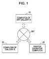
- Fig. 1 is an entire configuration diagram of a certification system.
- Fig. 2 is a block diagram showing the hardware configuration of a computer.
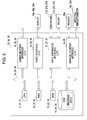
- Fig. 3 is a block diagram showing the software configuration of the certification system shown in Fig. 1 .
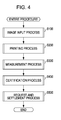
- Fig. 4 is a flowchart of an entire procedure performed by the certification system shown in Fig. 1 .
- Fig. 5 is a flowchart of an image input process.
- Fig. 6 is a schematic diagram showing the configuration for generating correction data.
- Fig. 7 is a diagram showing the configuration for measuring the spectral reflectance of a picture.
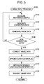
- Fig. 8 is a flowchart showing a printing process.
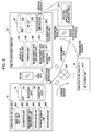
- Fig. 9 is a layout of patch data (image data) for certification.
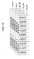
- Fig. 10 is a diagram showing a 3D-LUT.
- Fig. 11 is a schematic diagram showing a printing scheme of a printer.
- Fig. 12 is a flowchart of a measurement process.
- Fig. 13 is a flowchart of a certification process.
- Fig. 14 is a flowchart of a request and settlement process.
- Fig. 15 is a diagram showing a spectral reflectance database.
- Figs. 16A and 16B are diagrams showing a spectral Neugebauer model.
- Figs. 17A to 17C are diagrams showing a cellular Yule-Nielsen Spectral Neugebauer Model.
- Fig. 18 is a schematic diagram of a spectral reflectance-ink amount table.
- Fig. 19 is a flowchart of a creating process of a spectral reflectance-ink amount table.
- Fig. 20 is a diagram showing the software configuration of a certification system in accordance with a modified example.
- Fig. 1 is a diagram schematically showing computers and a network constituting a certification system including a computer 20 of a print operator according to this embodiment of the invention.
- the certification system includes at least a computer 10 of an art gallery A, a computer 20 of a print operator, and a computer 30 of an art gallery B, and the computers 10, 20 and 30 are communicably connected to one another through an Internet INT.
- the computers 10, 20 and 30 are connected to one another through the Internet INT.
- another communication medium such as a wired/wireless phone line may be interposed into the whole or a part of a communication line.
- Fig. 2 shows one example of the hardware configuration of each of the computers 10, 20 and 30.
- the computers 10, 20 and 30 in accordance with this embodiment have a substantially identical hardware configuration.
- the computer 10 includes a CPU 11, a RAM 12, a ROM 13, a hard disk drive (HDD) 14, a communication interface (I/F) 15, a video interface (I/F) 16, an input device interface (I/F) 17, a general purpose interface (I/F) 18, and a bus 19.
- the computer 20 includes a CPU 21, a RAM 22, a ROM 23, a HDD 24, a communication I/F 25, a video I/F 26, an input device I/F 27, a general purpose I/F 28, and a bus 29.
- the computer 30 includes a CPU 31, a RAM 32, a ROM 33, a HDD 34, a communication I/F 35, a video I/F 36, an input device I/F 37, and a bus 39.
- the CPUs 11, 21 and 31 develop program data stored in the ROMs 13, 23 and 33 and the HDDs 14, 24 and 34 to the RAMs 12, 22 and 32, and perform an operation for executing processes or functions which will be described later, respectively.
- the communication I/Fs 15, 25 and 35 provide mediation for connecting the computers 10, 20 and 30 to the Internet INT, respectively.
- the video I/Fs 16, 26 and 36 perform a process for outputting an image on external displays 16a, 26a and 36a.
- the input device I/Fs 17, 27 and 37 receive an operation through external keyboards 17a, 27a and 37a and external mice 17b, 27b and 37b, and transmit signals based on the operation to the CPUs 11, 21 and 31, respectively.
- the general purpose I/F 18 of the computer 10 of the art gallery A provides an interface for connecting the computer to an external spectral reflectometer 18b.
- the general purpose I/F 28 of the computer 20 of the print operator provides an interface for connecting the computer 20 to an external printer (a printing apparatus) 28a and an external spectral reflectometer 28b.
- These elements 11 to 18, 21 to 28 and 31 to 37 are communicably connected to one another through the buses 19, 29 and 39, and can perform a collaborative process by communicating with one another.
- the art gallery B exhibits a reproduced image PI of a picture D owned by the art gallery A for a constant period through an "art gallery A exhibition", and the picture D owned by the art gallery A corresponds to a target object to be reproduced in accordance with this embodiment of the invention.
- the computer 10 of the art gallery A, the computer 20 of the print operator, and the computer 30 of the art gallery B are provided in a single number. However, there may be more than one art gallery A, print operator, and art gallery B, and the computers 10, 20 and 30 may be provided in a plural number in correspondence with the number of the art galleries A, the number of the print operators, and the number of the art galleries B, respectively.
- Fig. 3 shows the software configuration and main data controlled by the computers 10, 20 and 30.
- an image data input unit M1, a calibration unit M2, a measurement data reception unit M3, a certification unit M4, a payment request unit M5, and a notification unit M6 are controlled.
- an image data obtaining unit M7, a printing unit M8, a measurement data obtaining unit M9, a measurement data transmission unit M10, a reception unit M11, and a consideration request unit M12 are controlled.
- a settlement unit M13 is controlled. Processes performed by each of the software modules M1 to M13 will be described in detail later.
- Fig. 4 schematically shows the flow of an entire procedure performed by the certification system in Fig. 1 .
- the computer 10 of the art gallery A performs the image input process (step S100), thereby obtaining image data ID.
- the computer 20 of the print operator performs the printing process (step S200) of printing the reproduced image PI and certification patches CC, and further performs the measurement process (step S300) of measuring the spectral characteristics of the certification patches CC.
- the computer 30 of the art gallery B performs the certification process (step S400).
- the request and settlement process step S500 is performed among the computer 10 of the art gallery A, the computer 20 of the print operator, and the computer 30 of the art gallery B.
- the art gallery B places an order with the art gallery A and the print operator for the reproduced image PI of the picture D owned by the art gallery A.
- This order may be electronically transmitted to the art gallery A, or may also be transmitted to the art gallery A by a letter and the like.
- information for specifying the picture D, the size of the reproduced image PI, a light source (a designated light source) when the art gallery B exhibits the reproduced image PI, and information for specifying a reproduction mode of the reproduced image PI are transmitted to the art gallery A and the print operator.
- the reproduction mode of the reproduced image PI any one of a spectral reflectance mode and a color value mode is designated.
- order data including the above-described information is transmitted to the computer 10 of the art gallery A and the computer 20 of the print operator from the computer 30 of the art gallery B.
- step S100 the entire procedure will be sequentially described starting from the image input process
- Fig. 5 shows the flow of the image input process.
- the image input process is performed by the computer 10 of the art gallery A having received the order, specifically, by the image data input unit M1 and the calibration unit M2.
- the spectral reflectometer 18b measures the spectral reflectances R( ⁇ ) of a reference sample.
- the spectral reflectances R( ⁇ ) obtained by measuring the reference sample are written as confirmation spectral reflectances R c ( ⁇ )
- the spectral reflectances R( ⁇ ) represent a reflectance group when irradiating lights having a plurality of wavelength sections in a visible wavelength band.
- the spectral reflectances R( ⁇ ) of the reference sample are written as reference spectral reflectances R i ( ⁇ ).
- the reference spectral reflectances R i ( ⁇ ) have been previously determined, and reference data 14a including the reference spectral reflectances R i ( ⁇ ) is stored in the HDD 13.
- the calibration unit M2 generates correction data 14b.
- Fig. 6 schematically shows the configuration for generating the correction data 14b.
- correction values R m ( ⁇ ) which are obtained by subtracting the confirmation spectral reflectances R c ( ⁇ ) from the reference spectral reflectances R i ( ⁇ ) with respect to each wavelength section, are stored as the correction data 14b.
- the generation dates of the correction data 14b are appended to the correction data 14b.
- the image data input unit M1 measures the spectral reflectances R( ⁇ ) of the picture D as a target object to be reproduced, thereby generating the image data ID.
- the correction values R m ( ⁇ ) are provided for each wavelength section.
- the correction values R m ( ⁇ ) may also be provided for each combination of each wavelength section and each spectral reflectance R( ⁇ ).
- tilt levels primary differential values obtained by differentiating the spectral reflectances R( ⁇ ) by wavelengths or secondary differential values obtained by differentiating the tilt levels by the wavelengths are combined with each combination of each wavelength section and each spectral reflectance R( ⁇ ), and the correction values R m ( ⁇ ) are provided for each of these combinations, so that the correction data 14b may also be created as 3D to 4D-LUTs.
- Fig. 7 is a diagram showing the configuration for measuring the spectral reflectance R( ⁇ ) of the picture D and generating the image data ID.
- the spectral reflectometer 18b has a stage 18b1, and the picture D is loaded on the stage 18b1.
- the stage 18b1 can be driven along an XY axis in the horizontal direction and the driving amount of the stage 18b1 is obtained with respect to the XY direction.
- the spectral reflectometer 18b measures the spectral reflectances R( ⁇ ) of each portion.
- the spectral reflectances R( ⁇ ) of each portion are sequentially stored in each pixel associated with the driving amount of the stage 18b1, thereby completing the generation of the image data ID in which each pixel existing in coordinates of the XY direction specified by the driving amount has the spectral reflectance R( ⁇ ).
- step S140 the calibration unit M2 calculates the difference between the current date and the generation date of the correction data 14b and determines whether the difference exceeds a predetermined threshold value (e.g., 10 days).
- a predetermined threshold value e.g. 10 days.
- step S110 is performed and the correction data 14b is generated anew.
- step S150 is performed.
- step S150 the calibration unit M2 corrects the spectral reflectances R( ⁇ ) by adding the correction values R m ( ⁇ ) to the spectral reflectances R( ⁇ ) of each pixel of the image data ID.
- the spectral reflectances R( ⁇ ) of the image data ID are corrected.
- the calibration unit M2 appends a certification flag to the image data ID (step S160), wherein the certification flag indicates that correction based on appropriate correction data 14b has been performed. That is, it is certified that the image data ID has been corrected based on new correction data 14b.
- the calibration unit M2 appends reference light source information to the image data ID (step S170), wherein the reference light source information specifies a light source (a reference light source) under which the picture D is exhibited in the art gallery A.
- the image data input unit M1 transmits the image data ID to the computer 20 of the print operator (step S180).
- Fig. 8 is a flowchart showing the printing process.
- the printing process is performed in the computer 20 of the print operator, which has received the order, specifically, by the image data obtaining unit M7 and the printing unit M8.
- step S205 the image data is received.
- step S210 the image data obtaining unit M7 determines whether the certification flag has been appended to the image data ID. That is, it is confirmed whether the correction based on the appropriate correction data 14b has been performed with respect to the image data ID.
- the printing process is ended. In this way, it is possible to prevent the reproduction image PI from being printed based on the image data ID in which the spectral reflectances R( ⁇ ) have not been appropriately corrected.
- correction of the image data ID based on new correction data 14b serves as certification conditions of the image data ID.
- step S220 is performed.
- the image data obtaining unit M7 obtains the image data ID transmitted from the computer 10 of the art gallery A.
- the printing unit M8 converts the image size of the image data ID.
- the size of the reproduction image PI is transmitted to the print operator, and the image size of the image data ID is converted based on the magnification of the size of the reproduction image PI and the print resolution of the printer 28a. In the case of reducing the size, thinning-out and the like are performed.
- pixels are inserted into the image data ID.
- the inserted pixels also include spectral reflectances R( ⁇ ) similarly to other pixels, but the spectral reflectances R( ⁇ ) are determined by an interpolation operation based on spectral reflectances R( ⁇ ) of adjacent pixels.
- the image data ID is laid out together with patch data 24b for certification.
- Fig. 9 shows the configuration of the layout in step S235.
- the image data ID having the converted size is allocated to an area of a printing paper having a predetermined size on which printing is performed, and the patch data 24b for certification stored in the HDD 23 is allocated to a blank space to which the image data ID is not allocated.
- the patch data 24b for certification is image data in which each pixel has spectral reflectance R( ⁇ ) similarly to the image data ID.
- pixels having the same spectral reflectance R( ⁇ ) are distributed in an area having a rectangular shape.
- Spectral reflectances R( ⁇ ) designated for each certification patch CC are obtained by measuring spectral reflectances R( ⁇ ) of a sample coated with pigments used for drawing the picture D. Usually, since pigments with a plurality of colors are used, a plurality of certification patches CC are formed. Since repairs are carried out in the case of an old picture D, the spectral reflectances R( ⁇ ) may be obtained by measuring a sample coated with pigments used at the time of the repair. Image data, to which the image data ID and the patch data 24b for certification are allocated, is written as print image data.
- step S240 the printing unit M8 performs the following diverging branched processes according to the reproduction mode of the reproduction image PI.
- the reproduction mode of the reproduction image PI is a spectral reflectance mode
- the printing unit M8 performs a color conversion process of converting the spectral reflectances R( ⁇ ) of each pixel into ink amount sets ⁇ which are a combination of ink amounts of CMYKlclm inks, which are ejected onto a printing paper by the printer 28a, in step S250.
- the ink amount sets ⁇ , with which the spectral reflectances R( ⁇ ) of each pixel are reproducible are calculated using a spectral printing model which will be described later.
- the spectral printing model As any ink amount set # is input, spectral reflectances R( ⁇ ) are output which are predicted to be reproduced on a printing paper when the printer 28a performs printing based on the ink amount set ⁇ .
- the ink amount sets ⁇ may not be calculated in reverse from the spectral reflectances R( ⁇ ) with which each pixel is reproducible.
- the printing unit M8 performs the following color conversion process, thereby sequentially obtaining the ink amount sets ⁇ with which the spectral reflectances R( ⁇ ) of each pixel are reproducible.
- target pixels for example, are selected in a pixel arrangement sequence, and the spectral reflectances R( ⁇ ) of the target pixels are obtained as target spectral reflectances R t ( ⁇ ) (step S250a).
- an appropriate ink amount set ⁇ is initially set in the spectral printing model (step S250b), and spectral reflectances R( ⁇ ) calculated by the initial setting are obtained as prediction spectral reflectances R s ( ⁇ ) (step S250c).
- the printing unit M8 determines whether an error (e.g., a Euclidean distance in spaces separated by wavelength sections) between the target spectral reflectances R t ( ⁇ ) and the prediction spectral reflectances R s ( ⁇ ) is smaller than a predetermined threshold value (step S250d).
- the threshold value is small to the extent that the target spectral reflectances R t ( ⁇ ) may be regarded to be equal to the prediction spectral reflectances R s ( ⁇ ).
- the ink amount set ⁇ is updated (step S250e), and the printing unit M8 returns to step S250c. That is, the printing unit M8 determines whether the error is smaller than the threshold value with respect to the updated ink amount set ⁇ .
- the current ink amount set ⁇ is employed as a solution and the ink amount set ⁇ is stored in the target pixel (step S250f).
- the printing unit M8 determines whether all pixels have been selected as the target pixel (step S250g). In the event that not all the pixels have been selected, the printing unit M8 returns to step S250a and performs a process of obtaining a solution of an ink amount set ⁇ with respect to the next target pixel.
- a solution of an ink amount set ⁇ with respect to a just previous pixel may be initially set with respect to the current target pixel in step S250b. In this way, the number of updates of an ink amount set ⁇ can be reduced. When all the pixels have been selected as the target pixel, the color conversion process is ended.
- the printing unit M8 performs a color conversion process based on color values in step S260.
- an ink amount set ⁇ is calculated, with which color values when observing an object of spectral reflectances R( ⁇ ) of each pixel under a reference light source are reproducible under a designated light source.
- a target pixel is selected and spectral reflectances R( ⁇ ) of the target pixel are obtained (step S260a).
- color values (target color values TCV) from the object when irradiating light of the reference light source onto the object of the obtained spectral reflectances R( ⁇ ) are calculated (step S260b).
- the spectral reflectances R( ⁇ ) are multiplied by spectral energy of the reference light source, and a color-matching function corresponding to a tristimulus value of a cone is further convoluted to the spectral reflectances R( ⁇ ), so that XYZ values are calculated.
- the XYZ values are converted into L*a*b values of a CIELAB color space, so that the L*a*b values are calculated as the target color values TCV.
- the target color value TCV represents a color value recognized by an observer when the picture D is exhibited in the art gallery A under the reference light source.
- ink amount sets ⁇ with which the target color values TCV are reproducible under the designated light source, are obtained (step S260c).
- the ink amount sets ⁇ corresponding to the target color values TCV are obtained with reference to a 3D-LUT 24a in which the correspondence relation between the target color values TCV and the ink amount sets ⁇ is provided for a plurality of lattice points.
- this embodiment uses the image data ID in which each pixel has the spectral reflectances R( ⁇ ) of the picture D.
- Fig. 10 shows the 3D-LUT 24a.
- the 3D-LUT 24a indicates table data in which the correspondence relation between the target color values TCV and the ink amount sets ⁇ is provided for lattice points substantially uniformly existing in the CIELAB color space serving as an input color space. An interpolation operation is performed with respect to peripheral lattice points based on the correspondence relation between the target color values TCV and the ink amount sets ⁇ , so that ink amount sets ⁇ corresponding to any target color values TCV are calculated.
- the 3D-LUT 24a is stored in the HDD 24, and is individually prepared for each of a plurality of designated light sources. This is because an ink amount set ⁇ for reproducing the same target color value TCV varies depending on the designated light source.
- the designated light source is a light source D50
- a 3D-LUT 24a created by measuring colors of color patches or estimating a reproduction color under the light source D50 is used.
- the ink amount set ⁇ is stored in the target pixel (step S260d).
- the printing unit M8 determines whether all pixels have been selected as the target pixel (step S260e). In the event that not all the pixels have been selected, the printing unit M8 returns to step S260a and performs a process of obtaining an ink amount set ⁇ with respect to the next target pixel.
- the color conversion process is ended. In this way, the print image data, in which each pixel has spectral reflectances R( ⁇ ), can be converted into ink amount image data in which each pixel has an ink amount set ⁇ .
- step S270 the printing unit M8 performs a halftone process with respect to the ink amount image data.
- ink amount sets ⁇ of 255 grayscale are made into low-level grayscales (grayscales indicating whether dots of a single size or dots of a plurality of sizes can be ejected) by using a dither method or an error diffusion method.
- step S280 a rasterization process is performed to allocate the halftone data obtained through the halftone process to each path or each nozzle of a print head provided in the printer 28a. In this way, print control data available for the printer 28a can be created.
- the printer 28a performs printing based on the print control data. Consequently, the reproduction image PI and the certification patches CC can be printed on the printing paper previously set in the printer 28a.
- Fig. 11 schematically shows a printing scheme of the printer 28a in this embodiment.
- the printer 28a includes a print head HD provided with a plurality of nozzles Nz for each ink of CMYKlclm, and control is performed based on print data PD to employ ink amounts of each ink of CMYKlclm ejected from the nozzles Nz as amounts designated by the above-described ink amount sets ⁇ (d c , d m , d y , d k , d lc and d lm ).
- the printing result of the reproduction image PI and the certification patches CC based on the image data ID and the patch data 24b for certification is equal to the layout shown in Fig. 9 .
- the reproduction image PI and the certification patches CC are printed on the same printing paper, so that the reproduction image PI and the certification patches CC are associated with each other.
- the reproduction image PI and the certification patches CC are not always printed on the same printing paper. For example, it may be possible to print a common and unique identification number or barcode on the reproduction image PI and the certification patches CC. However, since color reproduction characteristics of the printer 28a change as time passes, it is preferable that a printing interval between the reproduction image PI and the certification patches CC is as short as possible.
- the reproduction mode of the reproduction image PI is the spectral reflectance mode
- spectral reflectances R( ⁇ ) identical to those of the picture D are reproduced on the reproduction image PI
- spectral reflectances R( ⁇ ) equal to those of coating surfaces of pigments used for drawing the picture D are reproduced on the certification patches CC.
- the reproduction mode of the reproduction image PI is the color value mode
- a color value is obtained which is equal to the color value recognized when observing the picture D and the coating surfaces of the pigments used for drawing the picture D under the reference light source of the art gallery A. If the printing process is ended, the measurement process is subsequently performed by the computer 20 of the print operator.
- Fig. 12 is a flowchart of the measurement process.
- the measurement data obtaining unit M9 measures the spectral reflectances R( ⁇ ) of each printed certification patch CC by using the spectral reflectometer 28b (step S310).
- the reproduction mode of the reproduction image PI is the spectral reflectance mode (step S315)
- measurement data MD including spectral reflectances R( ⁇ ) obtained by measuring the certification patches CC is generated (step S320).
- the measurement data obtaining unit M9 appends the target spectral reflectances R t ( ⁇ ) when performing the color conversion process with respect to pixels corresponding to each certification patch CC to the measurement data MD as target data TD.
- step S335 color values when irradiating light of the designated light source with the spectral reflectances R( ⁇ ) obtained by measuring he certification patches CC are calculated (step S335), and measurement data MD including the calculated color values is generated (step S340).
- the color values can be calculated.
- spectral energy of the designated light source may be used instead of spectral energy of the reference light source.
- the spectral reflectances R( ⁇ ) are measured and the color values under the designated light source are indirectly obtained.
- step S350 the measurement data obtaining unit M9 appends the target color value TCV when performing the color conversion process with respect to the pixels corresponding to each certification patch CC to the measurement data MD as the target data TD.
- step S360 the measurement data transmission unit M10 transmits the measurement data MD to the computer 10 of the art gallery A, and ends the measurement process.
- Fig. 13 is a flowchart of the certification process performed by the certification unit M4 of the computer 10 of the art gallery A.
- the measurement data reception unit M3 receives the measurement data MD.
- the certification unit M4 determines the reproduction mode of the reproduction image PI based on the target data TD appended to the measurement data MD. That is, if the measurement data MD includes the target spectral reflectances R t ( ⁇ ), the certification unit M4 determines that the reproduction mode of the reproduction image PI is the spectral reflectance mode. If the measurement data MD includes the target color value TCV, the certification unit M4 determines that the reproduction mode of the reproduction image PI is the color value mode.
- the certification unit M4 calculates an error (e.g., a Euclidean distance in spaces separated by wavelength sections) between the target spectral reflectances R t ( ⁇ ) included in the target data TD and measured spectral reflectances R( ⁇ ) with respect to each certification patch CC (step S430). Then, the certification unit M4 decides whether certification is possible based on the errors of each certification patch CC (step S440).
- the possibility of the certification may be decided based on the comparison of the target spectral reflectances R t ( ⁇ ) included in the target data TD and the measured spectral reflectances R( ⁇ ), and various certification criteria may be used.
- the possibility of the certification may also be decided based on a value obtained by multiplying each certification patch CC by different weights and linearly combining the certification patches CC with one another.
- a hue (pigments), on which reproducibility is considered, is designated by the art gallery A, and a large weight may be applied to the error of the certification patch CC corresponding to the designated pigment.
- the maximum value of the error is less than a predetermined threshold value, it may be decided that the certification is possible.
- a standard deviation of the errors of each certification patch CC is less than the predetermined threshold value, it may also be decided that the certification is possible.
- the certification unit M4 calculates an error (e.g., color difference of a CIE1976) between the target color value TCV included in the target data TD and a measured color value with respect to each certification patch CC (step S450). Then, in step S440, the certification unit M4 decides whether certification is possible based on the errors of each certification patch CC. Herein, basically, when the error is small, it is decided that the certification is possible, and various certification criteria may be used.
- the notification unit M6 provides a notification, which indicates that the certification is impossible, to the computer 20 of the print operator and the computer 30 of the art gallery B (step S460). After receiving the notification, the computer 20 of the print operator performs calibration of the printer 28a, and performs the printing process again. Meanwhile, when it is decided that the certification is possible, the request and settlement process is performed.
- an error e.g., color difference of a CIE1976
- Fig. 14 is a flowchart of the request and settlement process. If the certification unit M4 of the computer 10 of the art gallery A decides that the certification is possible in step S440, the notification unit M6 provides a notification, which indicates that the certification is possible, to the computer 20 of the print operator and the computer 30 of the art gallery B (step S510). In step S520, the payment request unit M5 generates and transmits a payment request for the license fee required when the art gallery B exhibits the reproduction image PI. That is, the art gallery A provides the art gallery B with the opportunity of obtaining the license required when exhibiting the reproduction image PI only when the accuracy of reproducibility of the reproduction image PI is certified.
- the payment request includes at least permission for the exhibition of the reproduction image PI in the art gallery B and the amount of a consideration for the certification.
- the amount of the consideration depends on the reproduction mode of the reproduction image PI, and a large amount is set in the spectral reflectance mode as compared with the color value mode.
- the payment request may include particulars such as a permitted exhibition period of the reproduction image PI, a designated light source under which the reproduction image PI is to be exhibited and the like.
- the payment request is transmitted to the computer 30 of the art gallery B.
- the payment request and the notification indicating that the certification is possible may also be simultaneously transmitted to the computer 30 of the art gallery B.
- the reception unit M11 receives the notification indicating that the certification is possible (step S530). Then, the consideration request unit M12 generates a consideration request of the reproduction image PI and transmits the consideration request to the computer 30 of the art gallery B (step S540). Furthermore, after receiving the notification indicating that the certification is possible, the computer 20 of the print operator transmits the reproduction image PI to the art gallery B. It may be possible to print a verification mark, which indicates that the certification has been completed, on the rear surface or blank space of the reproduction image PI. In addition, it may also be possible to set the amount of the consideration according to the reproduction mode.
- the computer 30 of the art gallery B receives the payment request from the computer 10 of the art gallery A and the consideration request from the computer 20 of the print operator (step S550), and the settlement unit M13 performs a settlement process with respect to the payment request and the consideration request (step S560).
- the settlement unit M13 accesses a server (not shown) that manages bank accounts of the print operator and the art gallery A, and remits the money to the bank accounts. In this way, the request and settlement process is ended.
- the art gallery B can exhibit the reproduction image PI of the picture D owned by the art gallery A.
- the spectral characteristics of the reproduction image PI are guaranteed by the certification of the art gallery A based on the measurement data MD.
- the reputation of the picture D can be prevented from being damaged due to the exhibition of a degraded reproduction image PI from the art gallery A's collection, and a faithful exhibition can be made in the art gallery B's exhibition.
- the print operator prints the reproduction image PI with high accuracy, thereby obtaining the consideration for the printing of the reproduction image PI.
- the reproduction mode is the spectral reflectance mode
- the spectral reflectances R( ⁇ ) of the picture D are reproduced, and even if the reproduction image PI is exhibited under certain light sources, the reproduction image PI has color values equal to those of the picture D under the light sources.
- the reproduction mode is the color value mode
- the reproduction image PI exhibited under the designated light source has color values equal to those of the picture D under the reference light source.
- the spectral reflectance mode is better than the color value mode from the standpoint of the realization of complete reproducibility.
- the art gallery B has to exhibit the reproduction image PI under a designated light source different from the reference light source of the art gallery A
- the certification is performed based on the reproduction accuracy of a certification patch CC corresponding to pigments used for drawing or repairing the picture D, so that the entire reproduction accuracy of the picture D drawn using the pigment can be guaranteed with high reliability.
- a prediction model (the spectral printing model) used by the printing unit M8 is for estimating spectral reflectances R( ⁇ ), which are obtained when printing is performed at any ink amount sets ⁇ (d c , d m , d y , d k , d lc and d lm ) available for the printer 28a of this embodiment, as the prediction spectral reflectances R s ( ⁇ ), and corresponds to the function PM( ⁇ ) of Equation 1 above.
- a color patch is actually printed by a standard machine (the printer 28a) as to a plurality of representative points on an ink amount space, and a spectral reflectance database RDB obtained by measuring spectral reflectances R( ⁇ ) thereof by using a spectral reflectometer is prepared. Then, prediction using a cellular Yule-Nielsen Spectral Neugebauer model employing the spectral reflectance database RDB is performed, so that the spectral reflectance R( ⁇ ) is accurately predicted when the printing is performed at any ink amount sets ⁇ (d c , d m , d y , d k , d lc and d lm ).
- Fig. 15 shows the spectral reflectance database RDB.
- the spectral reflectance database RDB is a look-up table including the spectral reflectances R( ⁇ ), which is obtained when printing and measurement are actually performed regarding the ink amount sets ⁇ (d c , d m , d y , d k , d lc and d lm ) of a plurality of lattice points on the ink amount space (six dimensions in this embodiment, but only a CM surface is illustrated for the simplification of the drawing). For example, lattice points of 5 grids dividing each ink amount axis are generated.
- the spectral reflectances R( ⁇ ) of the other lattice points are predicted based on the spectral reflectances R( ⁇ ) of the lattice points which are actually used to perform the printing and the measurement, so that the number of the color patches on which the printing and the measurement are actually performed may be reduced.
- the spectral reflectance database RDB needs to be prepared for each printing paper with which the printer 28a can perform printing.
- the spectral reflectances R( ⁇ ) are determined by the spectral transmittance and the reflectance of the printing paper which are caused by an ink film (dot) formed on the printing paper, and are strongly influenced by the surface property (the dot shape depends thereon) or the reflectance of the printing paper.
- the printing unit M8 performs the prediction by the cellular Yule-Nielsen Spectral Neugebauer Model in which the spectral reflectance database RDB is used.
- the printing paper the glossy paper in this embodiment
- the ink amount set ⁇ are set as print conditions.
- the spectral reflectance database RDB created by printing the color patch on the glossy paper is set.
- the ink amount set ⁇ (d c , d m , d y , d k , d lc and d lm ) output from the ink amount set ⁇ calculating module M12 or the correction amount calculating module M16 is applied to the spectral printing model.
- the cellular Yule-Nielsen Spectral Neugebauer Model is based on the spectral Neugebauer model and the Yule-Nielsen model, which are well known. Furthermore, in the following description, a model in which 3 kinds of inks of CMY are used will be described for simple description.
- Figs. 16A and 16B are diagrams showing the spectral Neugebauer model.
- the prediction spectral reflectances R s ( ⁇ ) of a printed matter when the printing is performed at any ink amount set ⁇ (d c , d m , d y ) is given by Equation 1 below.
- R s ⁇ a w ⁇ R w ⁇ + a c ⁇ R c ⁇ + a m ⁇ R m ⁇ + a y ⁇ R y ⁇ + a r ⁇ R r ⁇ + a g ⁇ R g ⁇ + a b ⁇ R b ⁇ + a k ⁇ R k ⁇ 1
- a i is an area ratio of the i th region
- R i ( ⁇ ) is the spectral reflectance of the i th region.
- the suffix 'i' means a region (w) of no ink, a region (c) of the cyan ink only, a region (m) of the magenta ink only, a region (y) of the yellow ink only, a region (r) on which the magenta ink and the yellow ink are ejected, a region (g) on which the yellow ink and the cyan ink are ejected, a region (b) on which the cyan ink and the magenta ink are ejected, and a region (k) on which 3 colors of the CMY inks are ejected.
- f c , f m and f y are the proportions of the areas (called as "ink area coverage"), each of which is covered with the ink when only one kind of the CMY
- the ink area coverage f c , f m and f y are given by the Murray-Davies model shown in Fig. 16B .
- the ink area coverage f c of the cyan ink is a nonlinear function of the ink amount d c of the cyan ink.
- the ink amount d c can be converted into the ink area coverage f c by a one-dimensional lookup table.
- ink area coverage f c , f m and f y are a nonlinear function of the ink amounts d c , d m and d y is that when a small amount of ink is ejected onto a unit area, the ink spreads sufficiently, whereas when a large amount of ink is ejected, the inks overlap with each other so that there is not much increase in the covered area.
- the other kinds of the MY inks are also the same.
- Equation 1 When the Yule-Nielsen model is applied in relation to the spectral reflectance, Equation 1 above is rewritten as Equation 2a or Equation 2b below.
- Equation 2a and Equation 2b are equations representing the Yule-Nielsen Spectral Neugebauer Model.
- the cellular Yule-Nielsen Spectral Neugebauer Model employed in this embodiment is obtained by dividing the ink color space of the Yule-Nielsen Spectral Neugebauer Model described above into plural cells.
- Fig. 17A shows an example of cell division in the cellular Yule-Nielsen Spectral Neugebauer Model.
- the cell division is illustrated in a two-dimensional ink amount space including two axes of the ink amount d c and d m of the CM inks.
- the ink area coverage f c and f m uniquely relate to the ink amount d c and d m in the Murray-Davies model described above, the ink area coverage f c and f m may be considered as the axes representing the ink area coverage f c and f m .
- the white circles are the grid points (termed "lattice points") in the cell division.
- the two-dimensional ink amount (coverage) space is divided into nine cells C1 to C9.
- the ink amount set ⁇ (d c , d m ) corresponding to each lattice point is the ink amount set ⁇ corresponding to the lattice point defined in the spectral reflectance database RDB. That is, by referring to the spectral reflectance database RDB described above, the spectral reflectances R( ⁇ ) of each lattice point can be obtained. Therefore, the spectral reflectance R( ⁇ ) 00, R( ⁇ ) 10, R( ⁇ ) 20 ... R( ⁇ ) 33 of each lattice point can be obtained from the spectral reflectance database RDB.
- the cell division in this embodiment is also performed in the six-dimensional ink amount space of the CMYKlclm inks, and the coordinates of each lattice point also are expressed by the six-dimensional ink amount set ⁇ (d c , d m , d y , d k , d lc and d lm ).
- the spectral reflectance R( ⁇ ) of each lattice point corresponding to the ink amount set ⁇ (d c , d m , d y , d k , d lc and d lm ) of each lattice point is obtained from the spectral reflectance database RDB (for example, the spectral reflectance database of the glossy paper).
- Fig. 17B shows the relationship between the ink area coverage f c and the ink amount d c which are used in the cell division model.
- the ink amount range 0 to d cmax of one kind of ink is also divided into three sections, and the virtual ink area coverage f c used in the cell division model is obtained by the nonlinear curve which increases monotonically from 0 to 1 in every section.
- the ink area coverage f m and f y are also obtained with respect to other inks in the same manner.
- Fig. 17C shows a calculation method of the prediction spectral reflectances R s ( ⁇ ) when the printing is performed at any ink amount set ⁇ (d c , d m ) in a cell C5 located at the center position shown in Fig. 17A .
- the spectral reflectances R( ⁇ ) are given by Equation 3 below.
- Equation 3 the ink area coverage f c and f m are values given by the graph shown in Fig. 17B .
- the spectral reflectances R( ⁇ ) 11, ( ⁇ ) 12, ( ⁇ ) 21, and ( ⁇ ) 22 corresponding to four lattice points surrounding the cell C5 can be obtained by referring to the spectral reflectance database RDB. Therefore, all the values constituting the right side of Equation 3 can be confirmed, and as the calculation result, when the printing is performed at any ink amount set ⁇ (d c , d m ), the prediction spectral reflectances R s ( ⁇ ) can be calculated.
- the wavelength ⁇ is sequentially shifted in the visible wavelength band, so that the prediction spectral reflectances R s ( ⁇ ) can be obtained in the visible wavelength band.
- the prediction spectral reflectances R s ( ⁇ ) can be calculated with high accuracy as compared with the case of no division.
- the printing unit M8 can predict the prediction spectral reflectances R s ( ⁇ ) according to the ink amount set ⁇ sequentially updated.
- Fig. 18 is a schematic diagram of a spectral reflectance-ink amount table used for a color conversion process in accordance with the first modified example.
- the spectral reflectance-ink amount table 24c is stored in the HDD 23.
- the spectral reflectance-ink amount table 24c has an input space of a wavelength section number dimension, which employs spectral reflectances R( ⁇ ) of each wavelength section as an axis, and an output space is a space of an ink amount set ⁇ .
- spectral reflectances R( ⁇ ) of other wavelength sections are constant (e.g., 50%), and the section of the input space, in which only spectral reflectance R 400 ( ⁇ ) of a wavelength section 400 ⁇ 20nm and only spectral reflectance R 440 ( ⁇ ) of a wavelength section 440 ⁇ 20nm are changed, is shown.
- lattice points (indicated by circles) are provided on each intersection point of the orthogonal lattice, and an ink amount set ⁇ for reproducing spectral reflectance R( ⁇ ) of each lattice point is set to correspond to the section.
- Fig. 19 is a flowchart showing a creating sequence of the spectral reflectance-ink amount table 24c.
- the above-described spectral printing model is used. Basically, it is equal to the process for calculating the ink amount set ⁇ for reproducing the spectral reflectances R( ⁇ ) of each pixel in the above-described color conversion process.
- lattice points are generated on the orthogonal lattice points of the input space of the above-described spectral reflectances R( ⁇ ) (step S600).
- the lattice points having the number which is obtained by squaring the number of lattice points by the wavelength sections, are generated.
- any one of the lattice points is selected as a target lattice point, and spectral reflectances R( ⁇ ) of the target lattice point are obtained as target spectral reflectances R t ( ⁇ ) (step S610).
- an appropriate ink amount set ⁇ is initially set in the spectral printing model (step S620), and spectral reflectances R( ⁇ ) calculated by the initial setting are obtained as prediction spectral reflectances R s ( ⁇ ) (step S630) It is determined whether an error between the target spectral reflectances R t ( ⁇ ) and the prediction spectral reflectances R s ( ⁇ ) is smaller than a predetermined threshold value (step S640).
- the threshold value is small to the extent that the target spectral reflectances R t ( ⁇ ) may be regarded to be equal to the prediction spectral reflectances R s ( ⁇ ).
- the ink amount set ⁇ is updated (step S650), and step S630 is performed. That is, it is determined whether the error is smaller than the threshold value with respect to the updated ink amount set ⁇ .
- the current ink amount set ⁇ is employed as a solution and this ink amount set ⁇ is registered in the spectral reflectance-ink amount table 24c as an ink amount set ⁇ corresponding to a target lattice point (step S660).
- step S670 it is determined whether all lattice points have been selected as the target lattice point.
- step S610 is performed and a process is performed to obtain a solution of an ink amount set ⁇ with respect to the next target lattice point.
- step S620 a solution of an ink amount set ⁇ with respect to a just previous lattice point may be initially set with respect to the current target lattice point.
- the update of an ink amount set ⁇ may also be performed using the Jacobian matrix.
- An interpolation operation is performed with reference to the spectral reflectance-ink amount table 24c created as described above, so that the printing unit M8 can obtain ink amount sets ⁇ corresponding to the spectral reflectances R( ⁇ ) of each pixel.
- the printing may be stopped because it may be determined that the inputted image data ID is not reproducible.
- color conversion equal to that in the color value mode may also be performed.
- Fig. 20 shows a software configuration and main data which are controlled by the computers 10, 20 and 30.
- the measurement data reception unit M3, the certification unit M4, the payment request unit M5, and the notification unit M6 are controlled.
- the image data input unit M1, the calibration unit M2, the image data obtaining unit M7, the printing unit M8, the measurement data obtaining unit M9, the measurement data transmission unit M10, the reception unit M11, and the consideration request unit M12 are controlled.
- the image data input unit M1 and the calibration unit M2 are executed in the computer 20 of the print operator instead of the computer 10 of the art gallery A, differently from the previous embodiment. Therefore, the image input process is performed in the computer 20 of the print operator.
- the print operator may be requested to perform the procedure from the generation of the image data ID to the printing of the reproduction image PI, and only the certification process may be performed by the computer 10 of the art gallery A.
- the reproduction image PI destined to be exhibited is printed.
- the certification process can be performed with respect to the reproduction image PI printed as a pattern.
Landscapes
- Engineering & Computer Science (AREA)
- Multimedia (AREA)
- Signal Processing (AREA)
- Facsimile Image Signal Circuits (AREA)
- Color Image Communication Systems (AREA)
- Accessory Devices And Overall Control Thereof (AREA)
- Image Processing (AREA)
- Management, Administration, Business Operations System, And Electronic Commerce (AREA)
Abstract
Description
- The present invention relates to a printing apparatus, a printing method, and a computer-readable recording medium which records a program thereon so that the program prompts a computer to function as the printing apparatus.
- There is proposed an on-demand printing system in which when printing is needed, a customer requests as much printing as is needed and a price is charged corresponding to the amount of printing (refer to
JP-A-2006-146687 - However, it is problematic in that the quality of a quantity of printed matter may not satisfy the requirements of a consumer, and the consumer has to purchase a quantity of printed matter of an unintended quality. Particularly, when an art object such as a picture is reproduced using a quantity of printed matter, the requirements for the reproducibility of the art object are high and the requirements of the consumer may not be satisfied.
In addition, as a further demand, the provider that provides the reproduced art object desires to prevent duplicates of low reproducibility from being exhibited or distributed. - An advantage of some aspects of the invention is to provide a print operator terminal (a printing apparatus in the claims) capable of guaranteeing the reproducibility of a reproduced image.
- In a certification system including a print operator terminal according to an embodiment of the invention, the print operator terminal, a certifier terminal, and a consumer terminal are communicably connected to one another. In the certification system, first, an image data obtaining unit provided in the print operator terminal obtains image data including pixels for which spectral characteristics of a target object to be reproduced have been designated. A printing unit provided in the print operator terminal prints a reproduction image based on the image data and a plurality of certification patches, for which the spectral characteristics have been designated, while associating them with each other. A measurement data obtaining unit provided in the print operator terminal obtains measurement data by measuring the spectral characteristics of the certification patches. Next, a measurement data transmission unit provided in the print operator terminal transmits the measurement data to the certifier terminal.
- Then, a measurement data reception unit provided in the certifier terminal receives the measurement data. Next, a certification unit provided in the certifier terminal determines whether the certification of the reproduction image associated with the certification patches is possible on the basis of a comparison of the spectral characteristics of the measurement data and the spectral characteristics designated for the certification patches. When it is determined that the certification of the reproduction image is possible, a notification unit provided in the certifier terminal transmits a notification, which indicates that the certification of the reproduction image is possible, to the print operator terminal. In addition, a payment request unit provided in the certifier terminal transmits a payment request to the consumer terminal. Then, a reception unit provided in the print operator terminal receives the notification, which indicates that the certification of the reproduction image is possible, on the basis of the measurement data. Next, a consideration request unit provided in the print operator terminal transmits a consideration request for the printing of the reproduction image to the consumer terminal. Meanwhile, a settlement unit provided in the consumer terminal receives the payment request and the consideration request, and performs settlement with respect to the payment request and the consideration request.
- With such a configuration, the certification of the reproduction image may be performed on the basis of the comparison of the spectral characteristics of the measurement data and the spectral characteristics designated for the certification patches, and reproducibility of the reproduction image may be guaranteed. Since the settlement is performed for the certifier terminal having performed the certification in response to the payment request, the certifier terminal may obtain the consideration for the certification (license). Meanwhile, since the settlement also is performed for the print operator terminal having performed the printing in response to the consideration request, the print operator terminal may obtain the consideration for the printing of the certified reproduction image.
- Reproducibility of spectral reflectance is one example of the spectral characteristics evaluated in the certification.
If the reproducibility of spectral reflectance of the target object to be reproduced may be certified in the reproduction image, it may be possible to guarantee that the reproduction image is obtained, such that a color equal to that of the target object to be reproduced is shown, even under certain light sources. A color value is one example of the spectral characteristics evaluated in the certification. If it is possible to certify that a color under a reference light source of the target object to be reproduced is reproduced by the reproduction image under a designated light source, it may be possible to guarantee color reproducibility with respect to the reproduction image under the designated light source. It is preferable that the certification patch has the distinctive spectral characteristics of the reproduction image. When the target object to be reproduced is a picture drawn using pigments, it may be considered that the spectral characteristics of the target object to be reproduced are distinctive due to the pigment. In such a case, the certification patch is given the spectral characteristics of the pigment, resulting in the realization of certification with high reliability. - There is an appropriate printing scheme when printing is performed by a printing apparatus that prints the reproduction image and the certification patch by allowing a plurality of inks to adhere to a recording medium. That is, the printing unit specifies the ink amount of the inks, which are adhered to the recording medium by the printing apparatus with respect to each pixel of the image data, by referring to a look-up table which defines the correspondence relation of the spectral characteristics and the ink amount of the inks adhering to the recording medium. Particularly, when the spectral characteristic is the spectral reflectance, the look-up table is a table in which the ink amount is specified for each spectral reflectance defined by a combination of reluctances in a plurality of wavelength sections. Meanwhile, as a scheme for performing printing without using the look-up table, the ink amount of the inks for reproducing the spectral characteristics of each pixel of the image data may be specified based on a spectral characteristic prediction model. In addition, since the reproduction image to be certified is reproduced based on the image data, it is preferable that certification is also performed for the image data.
- Moreover, the technical scope of the invention can be realized by a detailed apparatus and a method performed by the apparatus. That is, the invention can be specified as a certification method including processes corresponding to each unit performed by the above-described certification system. Of course, when the above-described certification apparatus reads a program and realizes the above-described units, it goes without saying that the technical scope of the invention can be realized by a program for executing functions corresponding to the units, or various recording media on which the program is recorded.
Any combinations of the above-mentioned embodiments, where appropriate, are within the scope of the present invention. - The invention will be described with reference to the accompanying drawings, wherein like numbers reference like elements.
-
Fig. 1 is an entire configuration diagram of a certification system. -
Fig. 2 is a block diagram showing the hardware configuration of a computer. -
Fig. 3 is a block diagram showing the software configuration of the certification system shown inFig. 1 . -
Fig. 4 is a flowchart of an entire procedure performed by the certification system shown inFig. 1 . -
Fig. 5 is a flowchart of an image input process. -
Fig. 6 is a schematic diagram showing the configuration for generating correction data. -
Fig. 7 is a diagram showing the configuration for measuring the spectral reflectance of a picture. -
Fig. 8 is a flowchart showing a printing process. -
Fig. 9 is a layout of patch data (image data) for certification. -
Fig. 10 is a diagram showing a 3D-LUT. -
Fig. 11 is a schematic diagram showing a printing scheme of a printer. -
Fig. 12 is a flowchart of a measurement process. -
Fig. 13 is a flowchart of a certification process. -
Fig. 14 is a flowchart of a request and settlement process. -
Fig. 15 is a diagram showing a spectral reflectance database. -
Figs. 16A and 16B are diagrams showing a spectral Neugebauer model. -
Figs. 17A to 17C are diagrams showing a cellular Yule-Nielsen Spectral Neugebauer Model. -
Fig. 18 is a schematic diagram of a spectral reflectance-ink amount table. -
Fig. 19 is a flowchart of a creating process of a spectral reflectance-ink amount table. -
Fig. 20 is a diagram showing the software configuration of a certification system in accordance with a modified example. - Hereinafter, an embodiment of the present invention will be described according to the following sequence.
- A. Entire Configuration
- B. Image Input Process
- C. Printing Process
- D. Measurement Process
- E. Certification Process
- F. Request and Settlement Process
- G. Spectral Printing Model
- H. Modified Example
- H1. First Modified Example
- H2. Second Modified Example
-
Fig. 1 is a diagram schematically showing computers and a network constituting a certification system including acomputer 20 of a print operator according to this embodiment of the invention. Referring toFig. 1 , the certification system includes at least acomputer 10 of an art gallery A, acomputer 20 of a print operator, and acomputer 30 of an art gallery B, and thecomputers computers -
Fig. 2 shows one example of the hardware configuration of each of thecomputers computers computer 10 includes a CPU 11, a RAM 12, a ROM 13, a hard disk drive (HDD) 14, a communication interface (I/F) 15, a video interface (I/F) 16, an input device interface (I/F) 17, a general purpose interface (I/F) 18, and a bus 19. Thecomputer 20 includes aCPU 21, a RAM 22, a ROM 23, aHDD 24, a communication I/F 25, a video I/F 26, an input device I/F 27, a general purpose I/F 28, and abus 29. Thecomputer 30 includes aCPU 31, aRAM 32, a ROM 33, a HDD 34, a communication I/F 35, a video I/F 36, an input device I/F 37, and a bus 39. TheCPUs HDDs RAMs 12, 22 and 32, and perform an operation for executing processes or functions which will be described later, respectively. The communication I/Fs 15, 25 and 35 provide mediation for connecting thecomputers
The video I/Fs 16, 26 and 36 perform a process for outputting an image onexternal displays Fs 17, 27 and 37 receive an operation throughexternal keyboards external mice CPUs - The general purpose I/F 18 of the
computer 10 of the art gallery A provides an interface for connecting the computer to an externalspectral reflectometer 18b. The general purpose I/F 28 of thecomputer 20 of the print operator provides an interface for connecting thecomputer 20 to an external printer (a printing apparatus) 28a and an externalspectral reflectometer 28b. These elements 11 to 18, 21 to 28 and 31 to 37 are communicably connected to one another through thebuses 19, 29 and 39, and can perform a collaborative process by communicating with one another. The art gallery B exhibits a reproduced image PI of a picture D owned by the art gallery A for a constant period through an "art gallery A exhibition", and the picture D owned by the art gallery A corresponds to a target object to be reproduced in accordance with this embodiment of the invention. In addition, thecomputer 10 of the art gallery A, thecomputer 20 of the print operator, and thecomputer 30 of the art gallery B are provided in a single number. However, there may be more than one art gallery A, print operator, and art gallery B, and thecomputers -
Fig. 3 shows the software configuration and main data controlled by thecomputers computer 10 of the art gallery A, an image data input unit M1, a calibration unit M2, a measurement data reception unit M3, a certification unit M4, a payment request unit M5, and a notification unit M6 are controlled. In thecomputer 20 of the print operator, an image data obtaining unit M7, a printing unit M8, a measurement data obtaining unit M9, a measurement data transmission unit M10, a reception unit M11, and a consideration request unit M12 are controlled. In thecomputer 30 of the art gallery B, a settlement unit M13 is controlled. Processes performed by each of the software modules M1 to M13 will be described in detail later. -
Fig. 4 schematically shows the flow of an entire procedure performed by the certification system inFig. 1 . In this embodiment, first, thecomputer 10 of the art gallery A performs the image input process (step S100), thereby obtaining image data ID. Next, thecomputer 20 of the print operator performs the printing process (step S200) of printing the reproduced image PI and certification patches CC, and further performs the measurement process (step S300) of measuring the spectral characteristics of the certification patches CC. Then, thecomputer 30 of the art gallery B performs the certification process (step S400). Last, the request and settlement process (step S500) is performed among thecomputer 10 of the art gallery A, thecomputer 20 of the print operator, and thecomputer 30 of the art gallery B. Before the certification system performs each process which will be described later, the art gallery B places an order with the art gallery A and the print operator for the reproduced image PI of the picture D owned by the art gallery A. This order may be electronically transmitted to the art gallery A, or may also be transmitted to the art gallery A by a letter and the like. In relation to the order, information for specifying the picture D, the size of the reproduced image PI, a light source (a designated light source) when the art gallery B exhibits the reproduced image PI, and information for specifying a reproduction mode of the reproduced image PI are transmitted to the art gallery A and the print operator. As the reproduction mode of the reproduced image PI, any one of a spectral reflectance mode and a color value mode is designated. When the order is electronically transmitted to the art gallery A, order data including the above-described information is transmitted to thecomputer 10 of the art gallery A and thecomputer 20 of the print operator from thecomputer 30 of the art gallery B. Hereinafter, the entire procedure will be sequentially described starting from the image input process (step S100). -
Fig. 5 shows the flow of the image input process. The image input process is performed by thecomputer 10 of the art gallery A having received the order, specifically, by the image data input unit M1 and the calibration unit M2. In step S110, thespectral reflectometer 18b measures the spectral reflectances R(λ) of a reference sample. The spectral reflectances R(λ) obtained by measuring the reference sample are written as confirmation spectral reflectances Rc(λ) In addition, the spectral reflectances R(λ) represent a reflectance group when irradiating lights having a plurality of wavelength sections in a visible wavelength band. The spectral reflectances R(λ) of the reference sample are written as reference spectral reflectances Ri(λ). The reference spectral reflectances Ri(λ) have been previously determined, andreference data 14a including the reference spectral reflectances Ri(λ) is stored in the HDD 13. In step S120, the calibration unit M2 generatescorrection data 14b. -
Fig. 6 schematically shows the configuration for generating thecorrection data 14b. Herein, correction values Rm(λ), which are obtained by subtracting the confirmation spectral reflectances Rc(λ) from the reference spectral reflectances Ri(λ) with respect to each wavelength section, are stored as thecorrection data 14b. In addition, the generation dates of thecorrection data 14b are appended to thecorrection data 14b. In step S130, the image data input unit M1 measures the spectral reflectances R(λ) of the picture D as a target object to be reproduced, thereby generating the image data ID. In addition, in relation to thecorrection data 14b of this embodiment, the correction values Rm(λ) are provided for each wavelength section. However, in relation to thecorrection data 14b, the correction values Rm(λ) may also be provided for each combination of each wavelength section and each spectral reflectance R(λ). In addition, tilt levels (primary differential values) obtained by differentiating the spectral reflectances R(λ) by wavelengths or secondary differential values obtained by differentiating the tilt levels by the wavelengths are combined with each combination of each wavelength section and each spectral reflectance R(λ), and the correction values Rm(λ) are provided for each of these combinations, so that thecorrection data 14b may also be created as 3D to 4D-LUTs. -
Fig. 7 is a diagram showing the configuration for measuring the spectral reflectance R(λ) of the picture D and generating the image data ID. As shown inFig. 7 , thespectral reflectometer 18b has a stage 18b1, and the picture D is loaded on the stage 18b1. The stage 18b1 can be driven along an XY axis in the horizontal direction and the driving amount of the stage 18b1 is obtained with respect to the XY direction. Whenever portions of the picture D facing a fixed measurement probe 18b2 are changed little by little as the stage 18b1 moves in the XY direction, thespectral reflectometer 18b measures the spectral reflectances R(λ) of each portion. The spectral reflectances R(λ) of each portion are sequentially stored in each pixel associated with the driving amount of the stage 18b1, thereby completing the generation of the image data ID in which each pixel existing in coordinates of the XY direction specified by the driving amount has the spectral reflectance R(λ). By reducing the pitch of the driving amount in the XY direction of the stage 18b1, the resolution of the image data ID can be increased. - In step S140, the calibration unit M2 calculates the difference between the current date and the generation date of the
correction data 14b and determines whether the difference exceeds a predetermined threshold value (e.g., 10 days). When the difference exceeds the threshold value, step S110 is performed and thecorrection data 14b is generated anew. When the difference does not exceed the threshold value, step S150 is performed. In step S150, the calibration unit M2 corrects the spectral reflectances R(λ) by adding the correction values Rm(λ) to the spectral reflectances R(λ) of each pixel of the image data ID. Thus, the spectral reflectances R(λ) of the image data ID are corrected. In addition, the calibration unit M2 appends a certification flag to the image data ID (step S160), wherein the certification flag indicates that correction based onappropriate correction data 14b has been performed. That is, it is certified that the image data ID has been corrected based onnew correction data 14b. Furthermore, the calibration unit M2 appends reference light source information to the image data ID (step S170), wherein the reference light source information specifies a light source (a reference light source) under which the picture D is exhibited in the art gallery A. After the image data ID is generated as described above, the image data input unit M1 transmits the image data ID to thecomputer 20 of the print operator (step S180). -
Fig. 8 is a flowchart showing the printing process.
The printing process is performed in thecomputer 20 of the print operator, which has received the order, specifically, by the image data obtaining unit M7 and the printing unit M8. In step S205, the image data is received. In step S210, the image data obtaining unit M7 determines whether the certification flag has been appended to the image data ID. That is, it is confirmed whether the correction based on theappropriate correction data 14b has been performed with respect to the image data ID. When the certification flag has not been appended to the image data ID, the printing process is ended. In this way, it is possible to prevent the reproduction image PI from being printed based on the image data ID in which the spectral reflectances R(λ) have not been appropriately corrected. In this embodiment, correction of the image data ID based onnew correction data 14b serves as certification conditions of the image data ID. When the certification flag has been appended to the image data ID, step S220 is performed. In step S220, the image data obtaining unit M7 obtains the image data ID transmitted from thecomputer 10 of the art gallery A. In step S230, the printing unit M8 converts the image size of the image data ID. In the above-described order, the size of the reproduction image PI is transmitted to the print operator, and the image size of the image data ID is converted based on the magnification of the size of the reproduction image PI and the print resolution of theprinter 28a. In the case of reducing the size, thinning-out and the like are performed. In the case of enlarging the size, pixels are inserted into the image data ID. The inserted pixels also include spectral reflectances R(λ) similarly to other pixels, but the spectral reflectances R(λ) are determined by an interpolation operation based on spectral reflectances R(λ) of adjacent pixels. In step S235, the image data ID is laid out together withpatch data 24b for certification. -
Fig. 9 shows the configuration of the layout in step S235. Herein, the image data ID having the converted size is allocated to an area of a printing paper having a predetermined size on which printing is performed, and thepatch data 24b for certification stored in the HDD 23 is allocated to a blank space to which the image data ID is not allocated. Thepatch data 24b for certification is image data in which each pixel has spectral reflectance R(λ) similarly to the image data ID. In relation to thepatch data 24b for certification, pixels having the same spectral reflectance R(λ) are distributed in an area having a rectangular shape. Thus, it is possible to reproduce color patches (certification patches CC) having a rectangular shape. Spectral reflectances R(λ) designated for each certification patch CC are obtained by measuring spectral reflectances R(λ) of a sample coated with pigments used for drawing the picture D. Usually, since pigments with a plurality of colors are used, a plurality of certification patches CC are formed. Since repairs are carried out in the case of an old picture D, the spectral reflectances R(λ) may be obtained by measuring a sample coated with pigments used at the time of the repair. Image data, to which the image data ID and thepatch data 24b for certification are allocated, is written as print image data. - In step S240, the printing unit M8 performs the following diverging branched processes according to the reproduction mode of the reproduction image PI. When the reproduction mode of the reproduction image PI is a spectral reflectance mode, the printing unit M8 performs a color conversion process of converting the spectral reflectances R(λ) of each pixel into ink amount sets φ which are a combination of ink amounts of CMYKlclm inks, which are ejected onto a printing paper by the
printer 28a, in step S250. Herein, the ink amount sets φ, with which the spectral reflectances R(λ) of each pixel are reproducible, are calculated using a spectral printing model which will be described later. According to the spectral printing model, as any ink amount set # is input, spectral reflectances R(λ) are output which are predicted to be reproduced on a printing paper when theprinter 28a performs printing based on the ink amount set φ. Using the spectral printing model, the ink amount sets φ may not be calculated in reverse from the spectral reflectances R(λ) with which each pixel is reproducible. In this regard, in this embodiment, the printing unit M8 performs the following color conversion process, thereby sequentially obtaining the ink amount sets φ with which the spectral reflectances R(λ) of each pixel are reproducible. - First, target pixels, for example, are selected in a pixel arrangement sequence, and the spectral reflectances R(λ) of the target pixels are obtained as target spectral reflectances Rt(λ) (step S250a). Next, an appropriate ink amount set φ is initially set in the spectral printing model (step S250b), and spectral reflectances R(λ) calculated by the initial setting are obtained as prediction spectral reflectances Rs(λ) (step S250c). The printing unit M8 determines whether an error (e.g., a Euclidean distance in spaces separated by wavelength sections) between the target spectral reflectances Rt(λ) and the prediction spectral reflectances Rs(λ) is smaller than a predetermined threshold value (step S250d). In addition, the threshold value is small to the extent that the target spectral reflectances Rt(λ) may be regarded to be equal to the prediction spectral reflectances Rs(λ). When the error is larger than the threshold value, the ink amount set φ is updated (step S250e), and the printing unit M8 returns to step S250c. That is, the printing unit M8 determines whether the error is smaller than the threshold value with respect to the updated ink amount set φ. When the error is equal to or less than the threshold value, the current ink amount set φ is employed as a solution and the ink amount set φ is stored in the target pixel (step S250f). After the ink amount set φ is stored in the target pixel, the printing unit M8 determines whether all pixels have been selected as the target pixel (step S250g). In the event that not all the pixels have been selected, the printing unit M8 returns to step S250a and performs a process of obtaining a solution of an ink amount set φ with respect to the next target pixel. In addition, since it is highly probable that adjacent pixels have similar target spectral reflectances Rt(λ), a solution of an ink amount set φ with respect to a just previous pixel may be initially set with respect to the current target pixel in step S250b. In this way, the number of updates of an ink amount set φ can be reduced. When all the pixels have been selected as the target pixel, the color conversion process is ended. In relation to the update of the ink amount set φ in step S250e, for example, it may also be possible to update the ink amount set φ by using Newton's method using the Jacobian matrix having matrix elements obtained by partially differentiating each wavelength component of spectral reflectances R(λ) by means of each component of the ink amount set φ.
- Meanwhile, when the reproduction mode of the reproduction image PI is a color value mode, the printing unit M8 performs a color conversion process based on color values in step S260. Herein, an ink amount set φ is calculated, with which color values when observing an object of spectral reflectances R(λ) of each pixel under a reference light source are reproducible under a designated light source. First, a target pixel is selected and spectral reflectances R(λ) of the target pixel are obtained (step S260a). Next, color values (target color values TCV) from the object when irradiating light of the reference light source onto the object of the obtained spectral reflectances R(λ) are calculated (step S260b). In detail, the spectral reflectances R(λ) are multiplied by spectral energy of the reference light source, and a color-matching function corresponding to a tristimulus value of a cone is further convoluted to the spectral reflectances R(λ), so that XYZ values are calculated. The XYZ values are converted into L*a*b values of a CIELAB color space, so that the L*a*b values are calculated as the target color values TCV. The target color value TCV represents a color value recognized by an observer when the picture D is exhibited in the art gallery A under the reference light source. After the target color values TCV are calculated, ink amount sets φ, with which the target color values TCV are reproducible under the designated light source, are obtained (step S260c). Herein, the ink amount sets φ corresponding to the target color values TCV are obtained with reference to a 3D-
LUT 24a in which the correspondence relation between the target color values TCV and the ink amount sets φ is provided for a plurality of lattice points. In addition, this embodiment uses the image data ID in which each pixel has the spectral reflectances R(λ) of the picture D. However, in the case of the color value mode, it may be possible to use image data ID in which each pixel has color values (target color values TCV) of the picture D under the reference light source. -
Fig. 10 shows the 3D-LUT 24a. The 3D-LUT 24a indicates table data in which the correspondence relation between the target color values TCV and the ink amount sets φ is provided for lattice points substantially uniformly existing in the CIELAB color space serving as an input color space. An interpolation operation is performed with respect to peripheral lattice points based on the correspondence relation between the target color values TCV and the ink amount sets φ, so that ink amount sets φ corresponding to any target color values TCV are calculated. The 3D-LUT 24a is stored in theHDD 24, and is individually prepared for each of a plurality of designated light sources. This is because an ink amount set φ for reproducing the same target color value TCV varies depending on the designated light source. For example, when the designated light source is a light source D50, a 3D-LUT 24a created by measuring colors of color patches or estimating a reproduction color under the light source D50 is used. After the ink amount set φ is calculated as described above, the ink amount set φ is stored in the target pixel (step S260d). After the ink amount set φ is stored in the target pixel, the printing unit M8 determines whether all pixels have been selected as the target pixel (step S260e). In the event that not all the pixels have been selected, the printing unit M8 returns to step S260a and performs a process of obtaining an ink amount set φ with respect to the next target pixel. When all the pixels have been selected as the target pixel, the color conversion process is ended. In this way, the print image data, in which each pixel has spectral reflectances R(λ), can be converted into ink amount image data in which each pixel has an ink amount set φ. - In step S270, the printing unit M8 performs a halftone process with respect to the ink amount image data. For example, ink amount sets φ of 255 grayscale are made into low-level grayscales (grayscales indicating whether dots of a single size or dots of a plurality of sizes can be ejected) by using a dither method or an error diffusion method. In addition, in step S280, a rasterization process is performed to allocate the halftone data obtained through the halftone process to each path or each nozzle of a print head provided in the
printer 28a. In this way, print control data available for theprinter 28a can be created. In step S290, theprinter 28a performs printing based on the print control data. Consequently, the reproduction image PI and the certification patches CC can be printed on the printing paper previously set in theprinter 28a. -
Fig. 11 schematically shows a printing scheme of theprinter 28a in this embodiment. Theprinter 28a includes a print head HD provided with a plurality of nozzles Nz for each ink of CMYKlclm, and control is performed based on print data PD to employ ink amounts of each ink of CMYKlclm ejected from the nozzles Nz as amounts designated by the above-described ink amount sets φ (dc, dm, dy, dk, dlc and dlm). Ink droplets ejected from each nozzle Nz adhere to the printing paper as fine dots, and a printed image having ink area coverage according to the ink amount sets φ (dc, dm, dy, dk, dlc and dlm) resulting from the collection of a plurality of dots is formed on the printing paper. - The printing result of the reproduction image PI and the certification patches CC based on the image data ID and the
patch data 24b for certification is equal to the layout shown inFig. 9 . In this embodiment, the reproduction image PI and the certification patches CC are printed on the same printing paper, so that the reproduction image PI and the certification patches CC are associated with each other. However, the reproduction image PI and the certification patches CC are not always printed on the same printing paper. For example, it may be possible to print a common and unique identification number or barcode on the reproduction image PI and the certification patches CC. However, since color reproduction characteristics of theprinter 28a change as time passes, it is preferable that a printing interval between the reproduction image PI and the certification patches CC is as short as possible. When the reproduction mode of the reproduction image PI is the spectral reflectance mode, spectral reflectances R(λ) identical to those of the picture D are reproduced on the reproduction image PI, and spectral reflectances R(λ) equal to those of coating surfaces of pigments used for drawing the picture D are reproduced on the certification patches CC. Meanwhile, when the reproduction mode of the reproduction image PI is the color value mode, if the reproduction image PI and the certification patches CC are observed under the designated light source of the art gallery B, a color value is obtained which is equal to the color value recognized when observing the picture D and the coating surfaces of the pigments used for drawing the picture D under the reference light source of the art gallery A. If the printing process is ended, the measurement process is subsequently performed by thecomputer 20 of the print operator. -
Fig. 12 is a flowchart of the measurement process. The measurement data obtaining unit M9 measures the spectral reflectances R(λ) of each printed certification patch CC by using thespectral reflectometer 28b (step S310). When the reproduction mode of the reproduction image PI is the spectral reflectance mode (step S315), measurement data MD including spectral reflectances R(λ) obtained by measuring the certification patches CC is generated (step S320). In step S330, the measurement data obtaining unit M9 appends the target spectral reflectances Rt(λ) when performing the color conversion process with respect to pixels corresponding to each certification patch CC to the measurement data MD as target data TD. Meanwhile, when the reproduction mode of the reproduction image PI is the color value mode, color values when irradiating light of the designated light source with the spectral reflectances R(λ) obtained by measuring he certification patches CC are calculated (step S335), and measurement data MD including the calculated color values is generated (step S340). By the use of calculation equivalent to the calculation of the target color value TCV in step S260b, the color values can be calculated. However, spectral energy of the designated light source may be used instead of spectral energy of the reference light source. In addition, in this embodiment, the spectral reflectances R(λ) are measured and the color values under the designated light source are indirectly obtained. However, it may be possible to directly obtain color values through color measurement of a colorimeter after irradiating light of the designated light source onto the reproduction image PI. In step S350, the measurement data obtaining unit M9 appends the target color value TCV when performing the color conversion process with respect to the pixels corresponding to each certification patch CC to the measurement data MD as the target data TD. In step S360, the measurement data transmission unit M10 transmits the measurement data MD to thecomputer 10 of the art gallery A, and ends the measurement process. -
Fig. 13 is a flowchart of the certification process performed by the certification unit M4 of thecomputer 10 of the art gallery A. In step S410, the measurement data reception unit M3 receives the measurement data MD. In step S420, the certification unit M4 determines the reproduction mode of the reproduction image PI based on the target data TD appended to the measurement data MD. That is, if the measurement data MD includes the target spectral reflectances Rt(λ), the certification unit M4 determines that the reproduction mode of the reproduction image PI is the spectral reflectance mode. If the measurement data MD includes the target color value TCV, the certification unit M4 determines that the reproduction mode of the reproduction image PI is the color value mode. When the reproduction mode of the reproduction image PI is the spectral reflectance mode, the certification unit M4 calculates an error (e.g., a Euclidean distance in spaces separated by wavelength sections) between the target spectral reflectances Rt(λ) included in the target data TD and measured spectral reflectances R(λ) with respect to each certification patch CC (step S430). Then, the certification unit M4 decides whether certification is possible based on the errors of each certification patch CC (step S440). Herein, the possibility of the certification may be decided based on the comparison of the target spectral reflectances Rt(λ) included in the target data TD and the measured spectral reflectances R(λ), and various certification criteria may be used. For example, it may be possible to calculate an average value of the errors of each certification patch CC and decide that the certification is possible when the average value is less than a predetermined threshold value. Instead of a simple average value, the possibility of the certification may also be decided based on a value obtained by multiplying each certification patch CC by different weights and linearly combining the certification patches CC with one another. A hue (pigments), on which reproducibility is considered, is designated by the art gallery A, and a large weight may be applied to the error of the certification patch CC corresponding to the designated pigment. Furthermore, when the maximum value of the error is less than a predetermined threshold value, it may be decided that the certification is possible. In addition, when a standard deviation of the errors of each certification patch CC is less than the predetermined threshold value, it may also be decided that the certification is possible. - Meanwhile, when the reproduction mode of the reproduction image PI is the color value mode, the certification unit M4 calculates an error (e.g., color difference of a CIE1976) between the target color value TCV included in the target data TD and a measured color value with respect to each certification patch CC (step S450). Then, in step S440, the certification unit M4 decides whether certification is possible based on the errors of each certification patch CC. Herein, basically, when the error is small, it is decided that the certification is possible, and various certification criteria may be used. When it is decided that the certification is impossible, the notification unit M6 provides a notification, which indicates that the certification is impossible, to the
computer 20 of the print operator and thecomputer 30 of the art gallery B (step S460). After receiving the notification, thecomputer 20 of the print operator performs calibration of theprinter 28a, and performs the printing process again. Meanwhile, when it is decided that the certification is possible, the request and settlement process is performed. -
Fig. 14 is a flowchart of the request and settlement process. If the certification unit M4 of thecomputer 10 of the art gallery A decides that the certification is possible in step S440, the notification unit M6 provides a notification, which indicates that the certification is possible, to thecomputer 20 of the print operator and thecomputer 30 of the art gallery B (step S510). In step S520, the payment request unit M5 generates and transmits a payment request for the license fee required when the art gallery B exhibits the reproduction image PI. That is, the art gallery A provides the art gallery B with the opportunity of obtaining the license required when exhibiting the reproduction image PI only when the accuracy of reproducibility of the reproduction image PI is certified. The payment request includes at least permission for the exhibition of the reproduction image PI in the art gallery B and the amount of a consideration for the certification. The amount of the consideration depends on the reproduction mode of the reproduction image PI, and a large amount is set in the spectral reflectance mode as compared with the color value mode. Furthermore, the payment request may include particulars such as a permitted exhibition period of the reproduction image PI, a designated light source under which the reproduction image PI is to be exhibited and the like. In addition, in the case of providing an indefinite exhibition period, it may be possible to clearly define a period, in which identification of the reproducibility can be ensured, by taking the difference between discoloration of the picture D and discoloration of the reproduction image PI into consideration.
The payment request is transmitted to thecomputer 30 of the art gallery B. The payment request and the notification indicating that the certification is possible may also be simultaneously transmitted to thecomputer 30 of the art gallery B. - In the
computer 20 of the print operator, the reception unit M11 receives the notification indicating that the certification is possible (step S530). Then, the consideration request unit M12 generates a consideration request of the reproduction image PI and transmits the consideration request to thecomputer 30 of the art gallery B (step S540). Furthermore, after receiving the notification indicating that the certification is possible, thecomputer 20 of the print operator transmits the reproduction image PI to the art gallery B. It may be possible to print a verification mark, which indicates that the certification has been completed, on the rear surface or blank space of the reproduction image PI. In addition, it may also be possible to set the amount of the consideration according to the reproduction mode. Thecomputer 30 of the art gallery B receives the payment request from thecomputer 10 of the art gallery A and the consideration request from thecomputer 20 of the print operator (step S550), and the settlement unit M13 performs a settlement process with respect to the payment request and the consideration request (step S560). For example, the settlement unit M13 accesses a server (not shown) that manages bank accounts of the print operator and the art gallery A, and remits the money to the bank accounts. In this way, the request and settlement process is ended. - In accordance with this embodiment as described above, the art gallery B can exhibit the reproduction image PI of the picture D owned by the art gallery A. The spectral characteristics of the reproduction image PI are guaranteed by the certification of the art gallery A based on the measurement data MD. Thus, the reputation of the picture D can be prevented from being damaged due to the exhibition of a degraded reproduction image PI from the art gallery A's collection, and a faithful exhibition can be made in the art gallery B's exhibition. Meanwhile, the print operator prints the reproduction image PI with high accuracy, thereby obtaining the consideration for the printing of the reproduction image PI. When the reproduction mode is the spectral reflectance mode, the spectral reflectances R(λ) of the picture D are reproduced, and even if the reproduction image PI is exhibited under certain light sources, the reproduction image PI has color values equal to those of the picture D under the light sources. Meanwhile, when the reproduction mode is the color value mode, the reproduction image PI exhibited under the designated light source has color values equal to those of the picture D under the reference light source. The spectral reflectance mode is better than the color value mode from the standpoint of the realization of complete reproducibility. However, in the state in which the art gallery B has to exhibit the reproduction image PI under a designated light source different from the reference light source of the art gallery A, it is preferable to select the color value mode after designating the designated light source different from the reference light source. In any case, the certification is performed based on the reproduction accuracy of a certification patch CC corresponding to pigments used for drawing or repairing the picture D, so that the entire reproduction accuracy of the picture D drawn using the pigment can be guaranteed with high reliability.
- A prediction model (the spectral printing model) used by the printing unit M8 is for estimating spectral reflectances R(λ), which are obtained when printing is performed at any ink amount sets φ (dc, dm, dy, dk, dlc and dlm) available for the
printer 28a of this embodiment, as the prediction spectral reflectances Rs(λ), and corresponds to the function PM(φ) ofEquation 1 above.
In the spectral printing model, a color patch is actually printed by a standard machine (theprinter 28a) as to a plurality of representative points on an ink amount space, and a spectral reflectance database RDB obtained by measuring spectral reflectances R(λ) thereof by using a spectral reflectometer is prepared. Then, prediction using a cellular Yule-Nielsen Spectral Neugebauer model employing the spectral reflectance database RDB is performed, so that the spectral reflectance R(λ) is accurately predicted when the printing is performed at any ink amount sets φ (dc, dm, dy, dk, dlc and dlm). -
Fig. 15 shows the spectral reflectance database RDB.
As shown inFig. 15 , the spectral reflectance database RDB is a look-up table including the spectral reflectances R(λ), which is obtained when printing and measurement are actually performed regarding the ink amount sets φ (dc, dm, dy, dk, dlc and dlm) of a plurality of lattice points on the ink amount space (six dimensions in this embodiment, but only a CM surface is illustrated for the simplification of the drawing). For example, lattice points of 5 grids dividing each ink amount axis are generated. Herein, 513 lattice points are generated, and a vast amount of the color patches are necessarily printed and measured. However, since theprinter 28a actually has limitations on the number of the inks capable of being mounted at the same time or the amount of inks capable of being ejected at the same time, the number of the lattice points used in the printing and the measurement is reduced. - In addition, only a part of the lattice points is used for the printing and the measuring, and the spectral reflectances R(λ) of the other lattice points are predicted based on the spectral reflectances R(λ) of the lattice points which are actually used to perform the printing and the measurement, so that the number of the color patches on which the printing and the measurement are actually performed may be reduced. The spectral reflectance database RDB needs to be prepared for each printing paper with which the
printer 28a can perform printing. Strictly speaking, this is because the spectral reflectances R(λ) are determined by the spectral transmittance and the reflectance of the printing paper which are caused by an ink film (dot) formed on the printing paper, and are strongly influenced by the surface property (the dot shape depends thereon) or the reflectance of the printing paper. Next, the prediction by the cellular Yule-Nielsen Spectral Neugebauer Model in which the spectral reflectance database RDB is used will be described. - The printing unit M8 performs the prediction by the cellular Yule-Nielsen Spectral Neugebauer Model in which the spectral reflectance database RDB is used. In this prediction, the printing paper (the glossy paper in this embodiment) and the ink amount set φ are set as print conditions. When the prediction is performed on the glossy paper as the printing paper, the spectral reflectance database RDB created by printing the color patch on the glossy paper is set.
- If the setting of the spectral reflectance database RDB is possible, the ink amount set φ (dc, dm, dy, dk, dlc and dlm) output from the ink amount set φ calculating module M12 or the correction amount calculating module M16 is applied to the spectral printing model. The cellular Yule-Nielsen Spectral Neugebauer Model is based on the spectral Neugebauer model and the Yule-Nielsen model, which are well known. Furthermore, in the following description, a model in which 3 kinds of inks of CMY are used will be described for simple description. The same model is easily extended to a model using any ink amount set including the CMYKlclm according to this embodiment. In addition, as to the cellular Yule-Nielsen Spectral Neugebauer Model, Color Res Appl 25, 4-19, 2000 and R Balasubramanian, Optimization of the spectral Neugebauer model for printer characterization, J. Electronic Imaging 8(2), 156-166(1999) are cited.
-
Figs. 16A and 16B are diagrams showing the spectral Neugebauer model. In the spectral Neugebauer model, the prediction spectral reflectances Rs(λ) of a printed matter when the printing is performed at any ink amount set φ (dc, dm, dy) is given byEquation 1 below.
- aw =(1-f c )(1-f m )(1-f y )
- ac =f c (1-f m )(1-f y )
- am =(1-f c )f m (1-f y )
- ay =(1-f c )(1-f m )f y
- ar =(1-f c )f m f y
- ag =f c (1-f m )f y
- ab =f c f m (1-f y )
- ak =f c f m f y )
- In
Equation 1, ai is an area ratio of the ith region, and Ri(λ) is the spectral reflectance of the ith region. The suffix 'i' means a region (w) of no ink, a region (c) of the cyan ink only, a region (m) of the magenta ink only, a region (y) of the yellow ink only, a region (r) on which the magenta ink and the yellow ink are ejected, a region (g) on which the yellow ink and the cyan ink are ejected, a region (b) on which the cyan ink and the magenta ink are ejected, and a region (k) on which 3 colors of the CMY inks are ejected. In addition, fc, fm and fy are the proportions of the areas (called as "ink area coverage"), each of which is covered with the ink when only one kind of the CMY inks is ejected. - The ink area coverage fc, fm and fy are given by the Murray-Davies model shown in
Fig. 16B . In the Murray-Davies model, for example, the ink area coverage fc of the cyan ink is a nonlinear function of the ink amount dc of the cyan ink. For example, the ink amount dc can be converted into the ink area coverage fc by a one-dimensional lookup table. The reason that ink area coverage fc, fm and fy are a nonlinear function of the ink amounts dc, dm and dy is that when a small amount of ink is ejected onto a unit area, the ink spreads sufficiently, whereas when a large amount of ink is ejected, the inks overlap with each other so that there is not much increase in the covered area. The other kinds of the MY inks are also the same. - When the Yule-Nielsen model is applied in relation to the spectral reflectance,
Equation 1 above is rewritten as Equation 2a or Equation 2b below.
- In Equation 2a and Equation 2b, n is a predetermined coefficient equal to or more than 1, and for example, n can be set to 10. Equation 2a and Equation 2b are equations representing the Yule-Nielsen Spectral Neugebauer Model.
- The cellular Yule-Nielsen Spectral Neugebauer Model employed in this embodiment is obtained by dividing the ink color space of the Yule-Nielsen Spectral Neugebauer Model described above into plural cells.
-
Fig. 17A shows an example of cell division in the cellular Yule-Nielsen Spectral Neugebauer Model. Herein, for simple description, the cell division is illustrated in a two-dimensional ink amount space including two axes of the ink amount dc and dm of the CM inks. Furthermore, since the ink area coverage fc and fm uniquely relate to the ink amount dc and dm in the Murray-Davies model described above, the ink area coverage fc and fm may be considered as the axes representing the ink area coverage fc and fm. The white circles are the grid points (termed "lattice points") in the cell division. The two-dimensional ink amount (coverage) space is divided into nine cells C1 to C9. The ink amount set φ (dc, dm) corresponding to each lattice point is the ink amount set φ corresponding to the lattice point defined in the spectral reflectance database RDB. That is, by referring to the spectral reflectance database RDB described above, the spectral reflectances R(λ) of each lattice point can be obtained. Therefore, the spectral reflectance R(λ) 00, R(λ) 10, R(λ) 20 ... R(λ) 33 of each lattice point can be obtained from the spectral reflectance database RDB. - In practice, the cell division in this embodiment is also performed in the six-dimensional ink amount space of the CMYKlclm inks, and the coordinates of each lattice point also are expressed by the six-dimensional ink amount set φ (dc, dm, dy, dk, dlc and dlm). Then, the spectral reflectance R(λ) of each lattice point corresponding to the ink amount set φ (dc, dm, dy, dk, dlc and dlm) of each lattice point is obtained from the spectral reflectance database RDB (for example, the spectral reflectance database of the glossy paper).
-
Fig. 17B shows the relationship between the ink area coverage fc and the ink amount dc which are used in the cell division model. Herein, theink amount range 0 to dcmax of one kind of ink is also divided into three sections, and the virtual ink area coverage fc used in the cell division model is obtained by the nonlinear curve which increases monotonically from 0 to 1 in every section. The ink area coverage fm and fy are also obtained with respect to other inks in the same manner. -
Fig. 17C shows a calculation method of the prediction spectral reflectances Rs(λ) when the printing is performed at any ink amount set φ (dc, dm) in a cell C5 located at the center position shown inFig. 17A . When the printing is performed at the ink amount set φ (dc, dm), the spectral reflectances R(λ) are given byEquation 3 below.
- a 11=(1-f c)(1-f m)
- a 12=(1-f c)f m
- a 21=-f c(1-f m)
- a 22=f c f m)
- In
Equation 3, the ink area coverage fc and fm are values given by the graph shown inFig. 17B . In addition, the spectral reflectances R(λ) 11, (λ) 12, (λ) 21, and (λ) 22 corresponding to four lattice points surrounding the cell C5 can be obtained by referring to the spectral reflectance database RDB. Therefore, all the values constituting the right side ofEquation 3 can be confirmed, and as the calculation result, when the printing is performed at any ink amount set φ (dc, dm), the prediction spectral reflectances Rs(λ) can be calculated. The wavelength λ is sequentially shifted in the visible wavelength band, so that the prediction spectral reflectances Rs(λ) can be obtained in the visible wavelength band. When the ink amount space is divided into plural cells, the prediction spectral reflectances Rs(λ) can be calculated with high accuracy as compared with the case of no division. As described above, the printing unit M8 can predict the prediction spectral reflectances Rs(λ) according to the ink amount set φ sequentially updated. -
Fig. 18 is a schematic diagram of a spectral reflectance-ink amount table used for a color conversion process in accordance with the first modified example. The spectral reflectance-ink amount table 24c is stored in the HDD 23. The spectral reflectance-ink amount table 24c has an input space of a wavelength section number dimension, which employs spectral reflectances R(λ) of each wavelength section as an axis, and an output space is a space of an ink amount set φ. In the example ofFig. 18 , spectral reflectances R(λ) of other wavelength sections are constant (e.g., 50%), and the section of the input space, in which only spectral reflectance R400(λ) of awavelength section 400±20nm and only spectral reflectance R440(λ) of a wavelength section 440±20nm are changed, is shown. In the section, lattice points (indicated by circles) are provided on each intersection point of the orthogonal lattice, and an ink amount set φ for reproducing spectral reflectance R(λ) of each lattice point is set to correspond to the section. -
Fig. 19 is a flowchart showing a creating sequence of the spectral reflectance-ink amount table 24c. When creating the spectral reflectance-ink amount table 24c, the above-described spectral printing model is used. Basically, it is equal to the process for calculating the ink amount set φ for reproducing the spectral reflectances R(λ) of each pixel in the above-described color conversion process. First, lattice points are generated on the orthogonal lattice points of the input space of the above-described spectral reflectances R(λ) (step S600). Herein, the lattice points having the number, which is obtained by squaring the number of lattice points by the wavelength sections, are generated. After the lattice points are generated, any one of the lattice points is selected as a target lattice point, and spectral reflectances R(λ) of the target lattice point are obtained as target spectral reflectances Rt(λ) (step S610). Next, an appropriate ink amount set φ is initially set in the spectral printing model (step S620), and spectral reflectances R(λ) calculated by the initial setting are obtained as prediction spectral reflectances Rs(λ) (step S630) It is determined whether an error between the target spectral reflectances Rt(λ) and the prediction spectral reflectances Rs(λ) is smaller than a predetermined threshold value (step S640). - In addition, the threshold value is small to the extent that the target spectral reflectances Rt(λ) may be regarded to be equal to the prediction spectral reflectances Rs(λ). When the error is larger than the threshold value, the ink amount set λ is updated (step S650), and step S630 is performed. That is, it is determined whether the error is smaller than the threshold value with respect to the updated ink amount set φ. When the error is equal to or less than the threshold value, the current ink amount set φ is employed as a solution and this ink amount set φ is registered in the spectral reflectance-ink amount table 24c as an ink amount set φ corresponding to a target lattice point (step S660). If the ink amount set φ is registered with respect to the target lattice point, it is determined whether all lattice points have been selected as the target lattice point (step S670). When not all the lattice points have been selected, step S610 is performed and a process is performed to obtain a solution of an ink amount set φ with respect to the next target lattice point. Also, in step S620, a solution of an ink amount set φ with respect to a just previous lattice point may be initially set with respect to the current target lattice point. Furthermore, the update of an ink amount set φ may also be performed using the Jacobian matrix. The registration of ink amount sets φ corresponding to all lattice points is completed, resulting in the completion of the spectral reflectance-ink amount table 24c. In addition, as to all lattice points of the input space of the spectral reflectances R(λ), there exist no ink amount sets φ with which the spectral reflectances R(λ) of the lattice points are reproducible. Thus, when the error is not smaller than the threshold value even if the update of the ink amount set φ is repeated by the predetermined number of times, the lattice point is removed from the spectral reflectance-ink amount table 24c. Therefore, a region where there exist the lattice points registered in the spectral reflectance-ink amount table 24c indicates the range of the spectral reflectances R(λ) which are reproducible by the
printer 28a. - An interpolation operation is performed with reference to the spectral reflectance-ink amount table 24c created as described above, so that the printing unit M8 can obtain ink amount sets φ corresponding to the spectral reflectances R(λ) of each pixel. In addition, as to certain pixels, when spectral reflectances R(λ) out of the range of the spectral reflectances R(λ) which are reproducible by the
printer 28a are input, the printing may be stopped because it may be determined that the inputted image data ID is not reproducible. Furthermore, as to the pixels, color conversion equal to that in the color value mode may also be performed. -
Fig. 20 shows a software configuration and main data which are controlled by thecomputers computer 10 of the art gallery A, the measurement data reception unit M3, the certification unit M4, the payment request unit M5, and the notification unit M6 are controlled. In thecomputer 20 of the print operator, the image data input unit M1, the calibration unit M2, the image data obtaining unit M7, the printing unit M8, the measurement data obtaining unit M9, the measurement data transmission unit M10, the reception unit M11, and the consideration request unit M12 are controlled. In this modified example, the image data input unit M1 and the calibration unit M2 are executed in thecomputer 20 of the print operator instead of thecomputer 10 of the art gallery A, differently from the previous embodiment. Therefore, the image input process is performed in thecomputer 20 of the print operator. As described above, the print operator may be requested to perform the procedure from the generation of the image data ID to the printing of the reproduction image PI, and only the certification process may be performed by thecomputer 10 of the art gallery A. In the previous embodiment, the reproduction image PI destined to be exhibited is printed. However, even in the case of manufacturing goods (e.g., an underlay, a mouse pad and the like) having the reproduction image PI of the picture D owned by the art gallery A as a pattern, the certification process can be performed with respect to the reproduction image PI printed as a pattern.
Claims (11)
- A printing apparatus (20) comprising:an obtaining unit (M7) that obtains an image data of an image;a printing unit (M8) that prints patches showing spectral characteristics of reference pigments used for the image; anda consideration request unit (M12) that outputs a consideration request for a consideration of printing the image based on the obtained image data, wherein the consideration request is based on a certification notification with respect to measured spectral characteristics of the patches printed.
- The printing apparatus according to claim 1, wherein the spectral characteristics include a plurality of spectral reflectances or color values.
- The printing apparatus according to claim 1 or 2,
wherein the image data obtained by the obtaining unit includes spectral characteristics of the reference pigments used for the image. - The printing apparatus according to any one of claims 1 to 3, wherein
the image data of the image includes spectral characteristics of the obtained image, and
the printing unit (M8) specifies an ink amount used for printing the patches by referring to a look-up table that specifies a correspondence relation of the spectral characteristics obtained by the obtaining unit and the ink amount. - The printing apparatus according to claim 4, wherein the look-up table is a table in which the ink amount is specified for each of a plurality of spectral reflectances defined by a combination of reflectances in a plurality of wavelength ranges.
- The printing apparatus according to any one of claims 1 to 5, further comprising a measurement unit (M9) that measures the spectral characteristics of the patches printed.
- The printing apparatus according to any one of claims 1 to 6, further comprising
a data output unit (M10) that outputs the measured spectral characteristics of the patches printed, and
a data obtaining unit (M11) that obtains the certification notification based on the measured spectral characteristics of the patches printed. - The printing apparatus according to any one of claims 1 to 7, wherein the printing unit (M8) prints the image based on the obtained image data and a verification mark in accordance with the certification notification.
- The printing apparatus according to any one of claims 1 to 8, wherein the consideration request unit (M12) determines the consideration of printing based on a reproduction mode to print the image, wherein the reproduction mode is either one of spectral reflectance mode or color value mode.
- A printing method using a printer, the method comprising:obtaining an image data of an image;printing patches showing the spectral characteristics of reference pigments used for the image; andoutputting a consideration request for a consideration of printing the image based on the obtained image data, wherein the consideration request is based on certification notification with respect to measured spectral characteristics of the patches printed.
- A computer-readable recording medium recording a program thereon, the program prompting a computer to execute functions of:obtaining an image data of an image;printing patches showing spectral characteristics of reference pigments used for the image; andoutputting a consideration request for a consideration of printing the image based on the obtained image data, wherein the consideration request is based on a certification notification with respect to measured spectral characteristics of the patches printed.
Applications Claiming Priority (1)
| Application Number | Priority Date | Filing Date | Title |
|---|---|---|---|
| JP2009219602A JP2011070320A (en) | 2009-09-24 | 2009-09-24 | Authentication system, printer terminal and authenticating person's terminal |
Publications (2)
| Publication Number | Publication Date |
|---|---|
| EP2302898A2 true EP2302898A2 (en) | 2011-03-30 |
| EP2302898A3 EP2302898A3 (en) | 2011-10-19 |
Family
ID=43085960
Family Applications (1)
| Application Number | Title | Priority Date | Filing Date |
|---|---|---|---|
| EP10178668A Withdrawn EP2302898A3 (en) | 2009-09-24 | 2010-09-23 | A printing apparatus, a printing method, and a computer-readable recording medium recording a printing program thereon |
Country Status (4)
| Country | Link |
|---|---|
| US (1) | US20110069334A1 (en) |
| EP (1) | EP2302898A3 (en) |
| JP (1) | JP2011070320A (en) |
| CN (1) | CN102034037A (en) |
Families Citing this family (6)
| Publication number | Priority date | Publication date | Assignee | Title |
|---|---|---|---|---|
| US9686444B2 (en) | 2012-07-11 | 2017-06-20 | Hewlett-Packard Development Company, L.P. | Color separation and printing |
| WO2014173435A1 (en) | 2013-04-22 | 2014-10-30 | Hewlett-Packard Development Company L.P. | Spectral print mapping |
| JP7409189B2 (en) * | 2020-03-24 | 2024-01-09 | セイコーエプソン株式会社 | Color value prediction system and method for generating color value predictor |
| JP2021158398A (en) * | 2020-03-25 | 2021-10-07 | セイコーエプソン株式会社 | Method of creating teacher data, color prediction model creation apparatus, and method of creating color prediction model |
| CN116324350B (en) * | 2020-10-02 | 2025-09-23 | 富士胶片株式会社 | Image analysis method, image analysis device, program, and recording medium |
| JP7675635B2 (en) * | 2021-12-10 | 2025-05-13 | 株式会社Screenホールディングス | COLOR DATA CONVERSION METHOD, COLOR DATA CONVERSION DEVICE, AND COLOR DATA CONVERSION PROGRAM |
Citations (1)
| Publication number | Priority date | Publication date | Assignee | Title |
|---|---|---|---|---|
| JP2006146687A (en) | 2004-11-22 | 2006-06-08 | Nec Fielding Ltd | On-demand printing system |
Family Cites Families (13)
| Publication number | Priority date | Publication date | Assignee | Title |
|---|---|---|---|---|
| US7079270B2 (en) * | 2000-06-15 | 2006-07-18 | Fuji Xerox Co., Ltd. | Color image processing apparatus and color image processing system using the apparatus |
| JP4038998B2 (en) * | 2001-02-23 | 2008-01-30 | セイコーエプソン株式会社 | Printing with reduced color light source dependency |
| JP2005275855A (en) * | 2004-03-25 | 2005-10-06 | Seiko Epson Corp | Image output control device, client, image output device, image output instruction method, program, and recording medium |
| JP2005348067A (en) * | 2004-06-02 | 2005-12-15 | Konica Minolta Medical & Graphic Inc | Image output system and image output method |
| US8411162B2 (en) * | 2004-12-23 | 2013-04-02 | Hewlett-Packard Development Company, L.P. | Image processing methods and systems for fine art reproduction |
| GB2431791B (en) * | 2005-10-28 | 2010-12-01 | Hewlett Packard Development Co | A proofing method and apparatus |
| JP4739017B2 (en) * | 2005-12-28 | 2011-08-03 | キヤノン株式会社 | Color evaluation processing method, color evaluation processing device, computer program, and recording medium |
| JP4431897B2 (en) * | 2006-03-28 | 2010-03-17 | セイコーエプソン株式会社 | Image output control device and image output control method |
| JP4894489B2 (en) * | 2006-12-07 | 2012-03-14 | 富士ゼロックス株式会社 | Image processing apparatus and image reading apparatus |
| JP2009171556A (en) * | 2007-12-21 | 2009-07-30 | Seiko Epson Corp | Print control apparatus, print system, and print control program |
| US8199367B2 (en) * | 2007-12-21 | 2012-06-12 | Seiko Epson Corporation | Printing control device, printing system and printing control program |
| JP2009230739A (en) * | 2008-02-25 | 2009-10-08 | Seiko Epson Corp | Printing control apparatus, printing system, and printing control program |
| JP2010044746A (en) * | 2008-07-15 | 2010-02-25 | Seiko Epson Corp | Commodity dealing system and computer |
-
2009
- 2009-09-24 JP JP2009219602A patent/JP2011070320A/en not_active Withdrawn
-
2010
- 2010-09-13 CN CN2010102841075A patent/CN102034037A/en active Pending
- 2010-09-22 US US12/887,633 patent/US20110069334A1/en not_active Abandoned
- 2010-09-23 EP EP10178668A patent/EP2302898A3/en not_active Withdrawn
Patent Citations (1)
| Publication number | Priority date | Publication date | Assignee | Title |
|---|---|---|---|---|
| JP2006146687A (en) | 2004-11-22 | 2006-06-08 | Nec Fielding Ltd | On-demand printing system |
Non-Patent Citations (2)
| Title |
|---|
| R BALASUBRAMANIAN: "Optimization of the spectral Neugebauer model for printer characterization", J. ELECTRONIC IMAGING, vol. 8, no. 2, 1999, pages 156 - 166 |
| YULE-NIELSEN: "Spectral Neugebauer Model", COLOR RES APPL, vol. 25, 2000, pages 4 - 19 |
Also Published As
| Publication number | Publication date |
|---|---|
| JP2011070320A (en) | 2011-04-07 |
| US20110069334A1 (en) | 2011-03-24 |
| EP2302898A3 (en) | 2011-10-19 |
| CN102034037A (en) | 2011-04-27 |
Similar Documents
| Publication | Publication Date | Title |
|---|---|---|
| JP4528782B2 (en) | Generate a color conversion profile for printing | |
| JP5157856B2 (en) | Print control apparatus, print system, and print control program | |
| US9948830B2 (en) | Color estimation system, separation data generation system, color estimation method and separation data generation method | |
| EP2302898A2 (en) | A printing apparatus, a printing method, and a computer-readable recording medium recording a printing program thereon | |
| EP2629978B1 (en) | Image processing apparatus and image processing method | |
| US7898690B2 (en) | Evaluation of calibration precision | |
| JP2015134487A (en) | Printing control method and printing control apparatus | |
| US20150371124A1 (en) | Image processing apparatus and image processing program | |
| JP4561483B2 (en) | Determining the ink amount combination that reproduces the specified color | |
| US20100208304A1 (en) | Image correction method and image correction system | |
| JP6926744B2 (en) | Print color adjustment system and print color adjustment method | |
| EP2899964A2 (en) | Method for generating lookup table and color conversion device | |
| US20120147389A1 (en) | Calibration for maintaining quality of image | |
| US8314978B2 (en) | Halftone independent device characterization accounting for colorant interactions | |
| US20100014107A1 (en) | Printer driver and print control method | |
| JP3775457B2 (en) | Gradation reproduction method and apparatus for laser printer | |
| JP4985475B2 (en) | Print control apparatus, print system, and print control program | |
| US7748810B2 (en) | Image processing device, calibration table generator, image processing method, program product, and test pattern | |
| US7595910B2 (en) | Method for making a dot for dot proof | |
| JP5157873B2 (en) | Print control apparatus, print system, and print control program | |
| US11601569B2 (en) | Image processing device, image forming system, image processing method, and non-transitory computer-readable storage medium | |
| US20060126139A1 (en) | Error information acquiring method and print controlling method | |
| JP2012039320A (en) | Image processing system and image processing method | |
| JP5157872B2 (en) | Print control apparatus, print system, and print control program | |
| JP3910323B2 (en) | Profile creation method and profile creation apparatus |
Legal Events
| Date | Code | Title | Description |
|---|---|---|---|
| PUAI | Public reference made under article 153(3) epc to a published international application that has entered the european phase |
Free format text: ORIGINAL CODE: 0009012 |
|
| AK | Designated contracting states |
Kind code of ref document: A2 Designated state(s): AL AT BE BG CH CY CZ DE DK EE ES FI FR GB GR HR HU IE IS IT LI LT LU LV MC MK MT NL NO PL PT RO SE SI SK SM TR |
|
| AX | Request for extension of the european patent |
Extension state: BA ME RS |
|
| PUAL | Search report despatched |
Free format text: ORIGINAL CODE: 0009013 |
|
| AK | Designated contracting states |
Kind code of ref document: A3 Designated state(s): AL AT BE BG CH CY CZ DE DK EE ES FI FR GB GR HR HU IE IS IT LI LT LU LV MC MK MT NL NO PL PT RO SE SI SK SM TR |
|
| AX | Request for extension of the european patent |
Extension state: BA ME RS |
|
| RIC1 | Information provided on ipc code assigned before grant |
Ipc: H04N 1/60 20060101AFI20110914BHEP |
|
| 17P | Request for examination filed |
Effective date: 20120417 |
|
| 17Q | First examination report despatched |
Effective date: 20121112 |
|
| STAA | Information on the status of an ep patent application or granted ep patent |
Free format text: STATUS: THE APPLICATION IS DEEMED TO BE WITHDRAWN |
|
| 18D | Application deemed to be withdrawn |
Effective date: 20130323 |