EP2302830A2 - Extending physical downlink control channels - Google Patents
Extending physical downlink control channels Download PDFInfo
- Publication number
- EP2302830A2 EP2302830A2 EP10075539A EP10075539A EP2302830A2 EP 2302830 A2 EP2302830 A2 EP 2302830A2 EP 10075539 A EP10075539 A EP 10075539A EP 10075539 A EP10075539 A EP 10075539A EP 2302830 A2 EP2302830 A2 EP 2302830A2
- Authority
- EP
- European Patent Office
- Prior art keywords
- cell
- pdcch
- dci
- cells
- dss
- Prior art date
- Legal status (The legal status is an assumption and is not a legal conclusion. Google has not performed a legal analysis and makes no representation as to the accuracy of the status listed.)
- Granted
Links
- 238000000034 method Methods 0.000 claims abstract description 27
- 238000004891 communication Methods 0.000 claims abstract description 24
- 230000011664 signaling Effects 0.000 claims description 16
- 229920003045 dextran sodium sulfate Polymers 0.000 claims description 11
- 125000004122 cyclic group Chemical group 0.000 claims description 2
- 230000023402 cell communication Effects 0.000 claims 2
- 230000005540 biological transmission Effects 0.000 description 116
- 238000010586 diagram Methods 0.000 description 27
- 230000002776 aggregation Effects 0.000 description 18
- 238000004220 aggregation Methods 0.000 description 18
- 101150071746 Pbsn gene Proteins 0.000 description 13
- 238000013461 design Methods 0.000 description 10
- 239000000969 carrier Substances 0.000 description 7
- 230000008569 process Effects 0.000 description 6
- 238000012360 testing method Methods 0.000 description 5
- 238000012545 processing Methods 0.000 description 4
- 238000013468 resource allocation Methods 0.000 description 4
- 230000004044 response Effects 0.000 description 3
- 230000001174 ascending effect Effects 0.000 description 2
- 230000000903 blocking effect Effects 0.000 description 2
- 230000004069 differentiation Effects 0.000 description 2
- 230000008054 signal transmission Effects 0.000 description 2
- 101100082447 Arabidopsis thaliana PBL1 gene Proteins 0.000 description 1
- 101100184647 Azotobacter vinelandii modC1 gene Proteins 0.000 description 1
- 108010067463 CRC 220 Proteins 0.000 description 1
- 201000001432 Coffin-Siris syndrome Diseases 0.000 description 1
- 238000010794 Cyclic Steam Stimulation Methods 0.000 description 1
- 101150034584 MODD gene Proteins 0.000 description 1
- 101710173823 Short transient receptor potential channel 4 Proteins 0.000 description 1
- 101710173825 Short transient receptor potential channel 5 Proteins 0.000 description 1
- 101150080488 apa gene Proteins 0.000 description 1
- 230000001413 cellular effect Effects 0.000 description 1
- 238000007796 conventional method Methods 0.000 description 1
- 230000003247 decreasing effect Effects 0.000 description 1
- 230000001419 dependent effect Effects 0.000 description 1
- 238000001514 detection method Methods 0.000 description 1
- 230000000694 effects Effects 0.000 description 1
- 239000000463 material Substances 0.000 description 1
- 238000005259 measurement Methods 0.000 description 1
- 238000012986 modification Methods 0.000 description 1
- 230000004048 modification Effects 0.000 description 1
- 230000010363 phase shift Effects 0.000 description 1
- 238000000926 separation method Methods 0.000 description 1
- 230000003068 static effect Effects 0.000 description 1
Images


Classifications
-
- H—ELECTRICITY
- H04—ELECTRIC COMMUNICATION TECHNIQUE
- H04W—WIRELESS COMMUNICATION NETWORKS
- H04W72/00—Local resource management
- H04W72/20—Control channels or signalling for resource management
- H04W72/23—Control channels or signalling for resource management in the downlink direction of a wireless link, i.e. towards a terminal
-
- H—ELECTRICITY
- H04—ELECTRIC COMMUNICATION TECHNIQUE
- H04L—TRANSMISSION OF DIGITAL INFORMATION, e.g. TELEGRAPHIC COMMUNICATION
- H04L5/00—Arrangements affording multiple use of the transmission path
- H04L5/0001—Arrangements for dividing the transmission path
- H04L5/0003—Two-dimensional division
- H04L5/0005—Time-frequency
- H04L5/0007—Time-frequency the frequencies being orthogonal, e.g. OFDM(A), DMT
- H04L5/001—Time-frequency the frequencies being orthogonal, e.g. OFDM(A), DMT the frequencies being arranged in component carriers
-
- H—ELECTRICITY
- H04—ELECTRIC COMMUNICATION TECHNIQUE
- H04J—MULTIPLEX COMMUNICATION
- H04J11/00—Orthogonal multiplex systems, e.g. using WALSH codes
- H04J11/0069—Cell search, i.e. determining cell identity [cell-ID]
-
- H—ELECTRICITY
- H04—ELECTRIC COMMUNICATION TECHNIQUE
- H04L—TRANSMISSION OF DIGITAL INFORMATION, e.g. TELEGRAPHIC COMMUNICATION
- H04L5/00—Arrangements affording multiple use of the transmission path
- H04L5/003—Arrangements for allocating sub-channels of the transmission path
- H04L5/0053—Allocation of signaling, i.e. of overhead other than pilot signals
-
- H—ELECTRICITY
- H04—ELECTRIC COMMUNICATION TECHNIQUE
- H04W—WIRELESS COMMUNICATION NETWORKS
- H04W24/00—Supervisory, monitoring or testing arrangements
-
- H—ELECTRICITY
- H04—ELECTRIC COMMUNICATION TECHNIQUE
- H04W—WIRELESS COMMUNICATION NETWORKS
- H04W24/00—Supervisory, monitoring or testing arrangements
- H04W24/08—Testing, supervising or monitoring using real traffic
-
- H—ELECTRICITY
- H04—ELECTRIC COMMUNICATION TECHNIQUE
- H04W—WIRELESS COMMUNICATION NETWORKS
- H04W48/00—Access restriction; Network selection; Access point selection
- H04W48/08—Access restriction or access information delivery, e.g. discovery data delivery
- H04W48/10—Access restriction or access information delivery, e.g. discovery data delivery using broadcasted information
-
- H—ELECTRICITY
- H04—ELECTRIC COMMUNICATION TECHNIQUE
- H04W—WIRELESS COMMUNICATION NETWORKS
- H04W48/00—Access restriction; Network selection; Access point selection
- H04W48/08—Access restriction or access information delivery, e.g. discovery data delivery
- H04W48/12—Access restriction or access information delivery, e.g. discovery data delivery using downlink control channel
-
- H—ELECTRICITY
- H04—ELECTRIC COMMUNICATION TECHNIQUE
- H04W—WIRELESS COMMUNICATION NETWORKS
- H04W48/00—Access restriction; Network selection; Access point selection
- H04W48/16—Discovering, processing access restriction or access information
-
- H—ELECTRICITY
- H04—ELECTRIC COMMUNICATION TECHNIQUE
- H04W—WIRELESS COMMUNICATION NETWORKS
- H04W72/00—Local resource management
- H04W72/04—Wireless resource allocation
-
- H—ELECTRICITY
- H04—ELECTRIC COMMUNICATION TECHNIQUE
- H04W—WIRELESS COMMUNICATION NETWORKS
- H04W72/00—Local resource management
- H04W72/12—Wireless traffic scheduling
- H04W72/1263—Mapping of traffic onto schedule, e.g. scheduled allocation or multiplexing of flows
- H04W72/1273—Mapping of traffic onto schedule, e.g. scheduled allocation or multiplexing of flows of downlink data flows
-
- H—ELECTRICITY
- H04—ELECTRIC COMMUNICATION TECHNIQUE
- H04W—WIRELESS COMMUNICATION NETWORKS
- H04W76/00—Connection management
- H04W76/20—Manipulation of established connections
-
- H—ELECTRICITY
- H04—ELECTRIC COMMUNICATION TECHNIQUE
- H04W—WIRELESS COMMUNICATION NETWORKS
- H04W8/00—Network data management
- H04W8/26—Network addressing or numbering for mobility support
-
- H—ELECTRICITY
- H04—ELECTRIC COMMUNICATION TECHNIQUE
- H04L—TRANSMISSION OF DIGITAL INFORMATION, e.g. TELEGRAPHIC COMMUNICATION
- H04L5/00—Arrangements affording multiple use of the transmission path
- H04L5/0091—Signaling for the administration of the divided path
- H04L5/0092—Indication of how the channel is divided
-
- H—ELECTRICITY
- H04—ELECTRIC COMMUNICATION TECHNIQUE
- H04W—WIRELESS COMMUNICATION NETWORKS
- H04W4/00—Services specially adapted for wireless communication networks; Facilities therefor
- H04W4/06—Selective distribution of broadcast services, e.g. multimedia broadcast multicast service [MBMS]; Services to user groups; One-way selective calling services
-
- H—ELECTRICITY
- H04—ELECTRIC COMMUNICATION TECHNIQUE
- H04W—WIRELESS COMMUNICATION NETWORKS
- H04W56/00—Synchronisation arrangements
Definitions
- the present invention is directed to wireless communication systems and, more specifically, to extending a Physical Downlink Control CHannel (PDCCH) from supporting communication in a single cell to supporting communication in multiple cells.
- PDCH Physical Downlink Control CHannel
- a communication system includes a DownLink (DL) that supports the transmissions of signals from a Base Station (BS) (or Node B) to User Equipments (UEs), and an UpLink (UL) that supports transmissions of signals from UEs to the Node B.
- DL DownLink
- UE User Equipment
- UL UpLink
- a UE also commonly referred to as a terminal or a mobile station, may be fixed or mobile and may be a wireless device, a cellular phone, a personal computer device, etc.
- a Node B is generally a fixed station and may also be referred to as a Base Transceiver System (BTS), an access point, or some other similar terminology.
- BTS Base Transceiver System
- the DL signals include data signals that carry information content, control signals, and Reference Signals (RS), which are also known as pilot signals.
- the Node B transmits data information to a UE through a Physical Downlink Shared CHannel (PDSCH) and transmits control information to a UE through a PDCCH.
- PDSCH Physical Downlink Shared CHannel
- the UL signals also include data signals, control signals, and RSs.
- a UE transmits data information to the Node B through a Physical Uplink Shared CHannel (PUSCH) and transmits control information through a Physical Uplink Control CHannel (PUCCH). It is also possible for UEs to transmit control information through the PUSCH.
- PUSCH Physical Uplink Shared CHannel
- PUCCH Physical Uplink Control CHannel
- DCI Downlink Control Information
- DCI formats are used to provide DL Scheduling Assignments (SAs) for PDSCH receptions by the UEs, UL SAs for PUSCH transmissions by the UEs, or Transmission Power Control (TPC) commands for PUSCH receptions or PUCCH transmissions from the UEs.
- DCI formats also provide scheduling information for a Paging CHannel (PCH), for a response by the Node B to Random Access CHannels (RACH) transmitted by the UEs, and for Secondary Information Blocks (SIBs) providing broadcast control information from the Node B.
- PCH Paging CHannel
- RACH Random Access CHannels
- SIBs Secondary Information Blocks
- the DCI format for transmitting the TPC commands will be referred to as DCI format 3 and the DCI format for transmitting the scheduling information for the transmission of either PCH, RACH response, or SIBs will be referred to as DCI format 1C.
- the PDCCH is a major part of the total DL overhead and directly impacts the achievable DL cell throughput.
- a conventional method for reducing PDCCH overhead is to scale its size according to the resources required to transmit the DCI formats during a DL Transmission Time Interval (TTI).
- TTI Transmission Time Interval
- OFDMA Orthogonal Frequency Division Multiple Access
- CCFI Control Channel Format Indicator
- PCFICH Physical Control Format Indicator CHannel
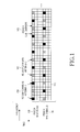
- FIG. 1 is a diagram illustrating a structure for the PDCCH transmission in the DL TTI, which for simplicity includes one sub-frame having M OFDM symbols.
- the PDCCH occupies the first N symbols 110.
- the remaining M-N symbols of the sub-frame are assumed to be primarily used for PDSCH transmission 120.
- the PCFICH 130 is transmitted in some sub-carriers, also referred to as Resource Elements (REs), of the first symbol.
- some sub-frame symbols include RS REs, 140 and 150, which are common to all UEs for each of the Node B transmitter antennas, which in FIG. 1 are assumed to be two.
- the RSs enable a UE to obtain a channel estimate for its DL channel medium and to perform various other measurements and functions.
- the PDSCH typically occupies the remaining REs 160.
- Additional control channels may be transmitted in the PDCCH region but, for brevity, they are not illustrated in FIG. 1 .
- a Physical Hybrid-HARQ Indicator CHannel (PHICH) may be transmitted by the Node B, in a similar manner as the PCFICH, to indicate to groups of UEs whether or not their previous PUSCH transmission was received by the Node B.
- the Node B separately codes and transmits each DCI format through a PDCCH.
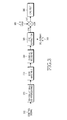
- FIG. 2 is a block diagram illustrating a conventional processing chain for transmitting a DCI format.
- the Medium Access Control (MAC) layer IDentity of the UE (or UE ID), for which a DCI format is intended, masks the Cyclic Redundancy Check (CRC) of the DCI format codeword in order to enable the reference UE to identify that the particular DCI format is intended for the reference UE.
- CRC Cyclic Redundancy Check
- the masked CRC is then appended to the DCI format bits 250, channel coding 260 is performed, for example, using a convolutional code, followed by rate matching 270 to the allocated PDCCH resources, and then interleaving and modulation 280. Thereafter, a control signal 290 is transmitted.
- a UE receiver performs the reverse operations of the Node B transmitter to determine whether a DCI format in the PDCCH was intended for the UE.
- FIG. 3 is a block diagram illustrating a conventional processing chain for receiving a DCI format.
- a received control signal i.e., a PDCCH, 310 is demodulated and the resulting bits are de-interleaved 320. Rate matching applied in the Node B transmitter is restored 330, and the output is subsequently decoded 340.
- the DCI format bits 360 are obtained, after extracting the CRC bits 350, which are then de-masked 370 by applying the XOR operation with the UE ID 380. Thereafter, the UE performs a CRC test 390. If the CRC test passes, the UE considers the DCI format as being valid and determines the parameters for PDSCH reception (DL DCI format) or PUSCH transmission (UL DCI format). If the CRC test does not pass, the UE disregards the DCI format.
- the information bits of the DCI format correspond to several Information Elements (IEs) such as, for example, the Resource Allocation (RA) IE indicating the part of the operating BandWidth (BW) allocated to a UE for PDSCH reception or PUSCH transmission, the Modulation and Coding Scheme (MCS) IE, the IE related to the HARQ operation, etc.
- IEs Information Elements
- the BW unit for PDSCH or PUSCH transmissions is assumed to consist of several REs, e.g., 12 REs, and will be referred to as a Physical Resource Block (PRB).
- PRB Physical Resource Block
- PDCCHs for a UE are not transmitted at fixed and predetermined locations and do not have predetermined coding rate. Consequently, a UE performs multiple PDCCH decoding operations in each sub-frame to determine whether any of the PDCCHs transmitted by the Node B is intended for the UE.
- the PDCCH REs are grouped into Control Channel Elements (CCEs) in the logical domain. For a given number of DCI format bits as illustrated in FIG. 2 , the number of CCEs for the respective PDCCH transmission depends on the channel coding rate.
- CCEs Control Channel Elements
- the Node B may respectively use a low or high channel coding rate in order to achieve a desired PDCCH BLock Error Rate (BLER). Therefore, a PDCCH transmission to a UE experiencing low DL SINR typically requires more CCEs that a PDCCH transmission to a UE experiencing high DL SINR. Alternatively, different power boosting of CCE REs may also be used in order to achieve a target BLER. Typical CCE aggregation levels for PDCCH transmissions are assumed to follow a "tree-based" structure, for example, 1, 2, 4, and 8 CCEs.
- a UE may determine a search space for a candidate PDCCH, after it restores the CCEs in the logical domain, according to a common set of CCEs for all UEs in a UE-Common Search Space (UE-CSS) and according to a UE-specific set of CCEs in a UE-Dedicated Search Space (UE-DSS).
- UE-CSS includes the first C CCEs in the logical domain.
- the UE-DSS may be determined according to a pseudo-random function having UE-common parameters as inputs, such as the sub-frame number or the total number of PDCCH CCEs in the sub-frame, and UE-specific parameters such as the identity assigned to a UE ( UE_ID ).
- UE-common parameters such as the sub-frame number or the total number of PDCCH CCEs in the sub-frame
- UE-specific parameters such as the identity assigned to a UE ( UE_ID ).
- the CCEs corresponding to PDCCH candidate m can be given by Equation (1).
- Exemplary values of M ( L ) for L ⁇ ⁇ 1,2,4,8 ⁇ are, respectively, ⁇ 6, 6, 2, 2 ⁇ .
- Y k 0 .
- DCI formats conveying information to multiple UEs, such as DCI format 3 or DCI format 1C, are transmitted in the UE-CSS. If enough CCEs remain after transmitting DCI formats 3 and 1C, the UE-CSS may also convey some DCI formats for PDSCH receptions or PUSCH transmissions by UEs. The UE-DSS exclusively conveys DCI formats for PDSCH receptions or PUSCH transmissions.
- the CCEs for the UE-CSS are placed first in the logical domain (prior to interleaving).
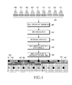
- FIG. 4 illustrates a conventional PDCCH transmission process. After channel coding and rate matching, as illustrated in FIG. 2 , the encoded DCI format bits are mapped to CCEs in the logical domain.
- the DCI format bits may be scrambled 440 using a binary scrambling code, which is typically cell-specific, and are subsequently modulated 450.
- a binary scrambling code which is typically cell-specific
- Each CCE is further divided into mini-CCEs. For example, a CCE including 36 REs can be divided into 9 mini-CCEs, each having 4 REs.
- Interleaving 460 is applied among mini-CCEs (blocks of 4 QPSK symbols).
- a block interleaver may be used where the interleaving is performed on symbol-quadruplets (4 Quadrature Phase Shift Keying (QPSK) symbols corresponding to the 4 REs of a mini-CCE) instead of on individual bits.
- QPSK Quadrature Phase Shift Keying
- the resulting series of QPSK symbols may be shifted by J symbols 470, and then each QPSK symbol is mapped to an RE 480 in the PDCCH region of the DL sub-frame.
- the REs in the PDCCH include QPSK symbols corresponding to DCI format for UE1 494, UE2 495, UE3 496, and UE4 497.
- aggregation of multiple carriers (or cells) can be used. For example, to support communication over 100 MHz, aggregation of five 20 MHz carriers (or cells) can be used.
- L-UEs Legacy-UEs
- A-UEs Advanced-UEs
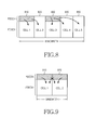
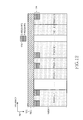
- FIG. 5 illustrates a principle of carrier aggregation.
- An operating BW of 100 MHz includes the aggregation of 5 (contiguous, for simplicity) carriers, 521, 522, 523, 524, and 525, each having a BW of 20 MHz.
- the sub-frame structure for communication over multiple carriers includes a PDCCH region, for example, 531 through 535, and a PDSCH region, for example, 541 and 545.
- FIG. 6 is a diagram illustrating a conventional heterogeneous network deployment.
- an area covered by a macro-Node B 610 encompasses areas covered by micro-Node Bs 620 and 630. Because the macro-Node B covers a larger area than a micro-Node B, its transmission power is substantially larger than the transmission power of a micro-Node B. Consequently, for topologies such as illustrated in FIG. 6 , the signals transmitted by a macro-Node B can cause severe interference to the signals transmitted by a micro-Node B. Interference coordination techniques can be applied to PDSCH transmissions to mitigate macro-to-micro interference using different PRBs between PDSCH signal transmissions from the macro-Node B and a micro-Node B. However, such interference coordination is not possible for the PDCCH because the CCEs are pseudo-randomly distributed over the entire operating BW, as was previously described.
- CI Carrier Indicator
- CI IE Cell Indicator
- a CI IE of 2 bits can indicate whether the DCI format is for the macro-cell or for any of a maximum of three micro-cells.
- PDCCH transmission in certain cells may be avoided for practical reasons. For example, it is desirable to avoid PDCCH transmissions in cells with small BW as they are inefficient and lead to large respective overhead. Also, PDSCH transmissions in a cell can be optimized to occur over all DL sub-frame symbols if transmissions of PDCCH and of other supporting signals such as UE-common RS, are avoided.
- the CI functionality can accommodate:
- FIG. 7 is a diagram illustrating a conventional PUSCH scheduling in the UL of multiple cells through PDCCH transmission in a single cell.
- a PDCCH in a single cell 710 is associated with the UL of two cells, 720 and 730. Consequently, PDCCHs scheduling PUSCH transmissions from Cell 1 and Cell 2 are transmitted in a single cell and the cell of PUSCH transmission can be identified by a CI IE consisting of 1 bit.
- FIG. 8 is a diagram illustrating a conventional PDSCH scheduling in a DL of multiple cells through PDCCH transmission in a single cell.
- FIG. 9 is a diagram illustrating a conventional PDCCH transmission in a first cell (macro-cell) and in a second cell (micro-cell), which may occur to avoid interference in PDCCH transmissions between a macro-cell and a micro-cell.
- both macro-cell and micro-cell may have PDSCH transmissions in Cell1 910 and Cell2 920, the macro-cell transmits PDCCH only in Cell1 and the micro-cell transmit PDCCH only in Cell2.
- the PDCCH size In communication systems having a single cell, the PDCCH is assumed to be limited to a maximum number of M OFDM symbols. In communication systems having multiple cells and having PDCCH transmission in a single cell, this limitation of the PDCCH size may cause scheduling restrictions. In general, the PDCCH size may need to be increased if the PDCCH in one cell performs scheduling in multiple cells.
- modification and expansion is needed in order to transmit multiple DCI formats to a UE in the PDCCH region of a single cell.
- An aspect of the present invention is to provide methods and apparatus for expanding a control region in a single cell from supporting transmission of DCI to a UE for communication over the single cell to supporting transmission of DCI to the UE for communication over multiple cells.
- a conventional control region in a single cell including a UE-CSS and a UE-DSS and supporting DCI transmission for the single cell, is expanded to support DCI transmission for multiple cells by including either multiple UE-CSS, each multiple UE-CSS corresponding to each of the multiple cells, or multiple UE-DSS, each multiple UE-DSS corresponding to each of the multiple cells, or both.
- support of DCI transmission for multiple cells, each having a Cell Identity (Cell_ID), through a control region in a single cell is provided by informing the UE of the Cell_ID for each of the multiple cells and then defining a distinct UE-DSS for each of the multiple cells in the control region of the single cell, where each distinct UE-DSS has the same structure as the UE-DSS for DCI transmission over only the single cell and its location additionally depends only on the respective Cell_ID.
- the DCI is conveyed through DCI formats and DCI formats in each UE-DSS may include a CI IE that is derived from the Cell_ID.
- support of DCI transmission for multiple cells through a control region in a primary cell is provided by defining a first control region for DCI transmission corresponding to a first set of cells that includes the primary cell, and a second control region for DCI transmission corresponding to a second set of cells including the multiple cells that are not in the first set of cells.
- the first control region includes the same resources as the control region for DCI transmission only in the primary cell.
- the second control region includes resources that would otherwise be used for data transmission in the primary cell.
- OFDM Orthogonal Frequency Division Multiple Access
- SC-FDMA Single-Carrier Frequency Division Multiple Access
- OFDM Frequency Division Multiplexing
- SC-FDMA Single-Carrier Frequency Division Multiple Access
- OFDM Orthogonal Frequency Division Multiple Access
- FDMA Frequency Division Multiplexing
- DFT Discrete Fourier Transform
- an A-UE is semi-statically configured, for example, through Radio Resource Control (RRC) signaling, the cells over which it may have PDSCH reception or PUSCH transmission.
- RRC Radio Resource Control
- a link between the DL and the UL in those cells may also be configured.
- the inclusion of the CI IE in DCI formats can be either UE-specific or cell-specific.
- each A-UE is informed through higher layer signaling (MAC or RRC signaling) whether its assigned DCI formats in a cell include a CI IE.
- MAC or RRC signaling When the CI IE in DCI formats is cell-specific, the Node B may broadcast whether a CI IE is included in the DCI formats.
- the DCI formats having the CI IE may be all DCI formats or a predetermined subset of DCI formats.
- DCI formats in the UE-CSS may not contain CI while DCI formats in the UE-DSS may contain CI.
- FIG. 10 is a diagram illustrating a method of informing an A-UE whether a CI IE is included in DCI formats in a UE-specific manner, according to an embodiment of the present invention.
- an A-UE is configured in the DL of Cell1 1010, Cell2 1020, and Cell3 1030 for PDSCH reception and in the UL of Cell1 1040 and Cell2 1050 for PUSCH transmission.
- the cells of PDCCH transmission are also informed to the A-UE through higher layer signaling.
- a PDCCH is transmitted only in Cell1 1060.
- the DL and UL for Cell1 may correspond to a macro-cell, while the DL and UL of Cell2 may correspond to a first micro-cell and the DL of Cell3, and the UL of Cell2 can correspond to a second micro-cell.
- DCI formats associated with PUSCH transmissions or with TPC for PUSCH or PUCCH transmissions (DCI format 3) will be referred to as UL DCI formats.
- the remaining DCI formats are associated with PDSCH receptions and will be referred to as DL DCI formats.
- DL DCI formats to the UE include a CI IE having 2 bits.
- the CI values of '00', '01", and “10” can correspond to Cell1, Cell2, and Cell3, respectively, while the CI value "11" is unused.
- the CI values of '0' and “1" can correspond to Cell1 and Cell2, respectively.
- the number of bits for the CI IE can be different between DL DCI formats and UL DCI formats (including, for example, not having any CI IE bits in UL DCI formats while having CI IE bits in DL DCI formats).
- the association between CI values and Cells may also be implicitly determined. For example, ascending CI values of "00", “01", “10", and “11” can be mapped to Cells in order of increasing carrier frequency.
- CI may not be necessary for cells with different BWs because the respective DCI formats may have different sizes. For example, for 2 cells, where the PDCCH is transmitted only in one cell, the CI inclusion in the DL DCI formats is not necessary if, for example, one cell has a BW of 20 MHz and the other cell has a BW of 5 MHz.
- the primary reason for having a different DCI format size for different BWs is the Resource Allocation (RA) IE in the DCI formats, which should have a larger size for cells with larger BWs, as it addresses a larger number of PRBs.
- RA Resource Allocation
- the transmission of DCI formats to L-UEs is supported with the conventional PDCCH structure.
- the PDCCH transmission to A-UEs having PDSCH reception or PUSCH transmission in the same cell is also supported with the conventional PDCCH structure.
- such A-UEs will be referred to as Primary-UEs (P-UEs) and the cell with the PDCCH transmission as Primary-cell (Pcell).
- P-UEs Primary-UEs
- Pcell Primary-cell
- A-UEs having PDSCH reception or PUSCH transmission in a cell other than the Pcell will be referred to as Secondary-UEs (S-UEs) and the corresponding cells as Secondary-cells (Scells).
- UEs receiving PDSCH in Cell1 are P-UEs and Cell1 is the Pcell
- UEs receiving PDSCH in Cell2 are S-UEs and Cell2 is a Scell
- An A-UE can be both a P-UE and an S-UE depending on the cell (Pcell or Scell, respectively). Therefore, the classification of an A-UE as a P-UE or an S-UE is unique for each cell and may be different among cells as an A-UE can be a P-UE in the Pcell and the S-UE in an Scell.
- the conventional PDCCH structure or a separate PDCCH structure may be used.
- the capacity (first M OFDM symbols of the DL sub-frame) of the conventional PDCCH structure is not reached for scheduling P-UEs
- Whether the conventional PDCCH structure or an Extended PDCCH (E-PDCCH) structure is used can be predetermined or be informed by the Node B through broadcast signaling or through UE-specific higher layer signaling.
- the PDCCH CCEs for an A-UE can be either in the PDCCH or in the E-PDCCH, but not in both.
- Whether an A-UE monitors the PDCCH or the E-PDCCH for scheduling a PDSCH or a PUSCH in a specific cell can be semi-statically configured either through higher layer signaling or through broadcast signaling.
- E-PDCCH in the Pcell is used for scheduling a PDSCH or a PUSCH in Scells, the following is considered, in accordance with an embodiment of the present invention:
- the E-PDCCH provides an extension to the PDCCH and therefore, conveys information of the same nature.
- the E-PDCCH may include a respective PCFICH (referred to as an E-PCFICH) and a PHICH (referred to as an E-PHICH) for PUSCH transmissions in Scells served by the E-PDCCH.
- E-PCFICH referred to as an E-PCFICH
- E-PHICH PHICH
- the DCI formats in the E-PDCCH are transmitted in CCEs, but the CCE allocation is in PRBs as the E-PDCCH is orthogonally multiplexed with the PDSCH.
- the PRBs for the E-PDCCH can be semi-statically or dynamically configured. A semi-static configuration of E-PDCCH PRBs ensures adequate separation in the frequency domain in order to obtain frequency diversity or that the PRBs are selected according to an interference co-ordination technique minimizing interference from adjacent cells.
- the first E-PDCCH symbol can be the first OFDM symbol after the last actual PDCCH OFDM symbol or the first symbol after the last PDCCH OFDM symbol, assuming the maximum number of PDCCH OFDM symbols.
- S-UEs decode the PCFICH to determine the E-PDCCH start.
- the first E-PDCCH symbol is the first symbol after the last PDCCH OFDM symbol assuming the maximum number of PDCCH OFDM symbols, maximum E-PDCCH decoding latency results, but errors from incorrect PCFICH detection, which will lead in PDCCH decoding failure, are avoided.
- the last E-PDCCH symbol can be statically, semi-statically, or dynamically configured.
- the last E-PDCCH symbol can be, for example, the seventh symbol of the DL sub-frame.
- the last E-PDCCH symbol can be informed by the Node B through a broadcast channel.
- the last E-PDCCH symbol can be informed through the E-PCFICH.
- the range of OFDM symbols indicated by the E-PCFICH for the E-PDCCH can be different than the range of OFDM symbols indicated by the PCFICH for the PDCCH.
- the E-PCFICH may also indicate 0 OFDM symbols for the E-PDCCH in which case the E-PCFICH and the E-PHICH may be transmitted in the PDCCH.
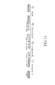
- FIG. 11 illustrates an E-PDCCH multiplexing structure where A-UEs assume a maximum PDCCH size to determine a first E-PDCCH symbol, according to an embodiment of the present invention.
- the PDCCH transmission 1110 has 2 OFDM symbols, out of a maximum of 3 PDCCH OFDM symbols.
- the first E-PDCCH symbol is the first OFDM symbol after the PDCCH transmission, assuming the maximum of 3 OFDM symbols. Therefore, the first E-PDCCH symbol is the fourth OFDM symbol of the DL sub-frame.
- the E-PCFICH transmission (not shown) is always in the first E-PDCCH symbol and, for the structure of FIG. 11 , it indicates that the E-PDCCH is transmitted in 2 OFDM symbols 1120.
- the E-PDCCH transmission PRBs 1130 are semi-statically configured through broadcast signaling by the Node B (for example, in an SIB).
- the E-PDCCH transmission is multiplexed with PDSCH transmissions to various UEs, 1140, 1150, and 1160.
- PDSCH transmissions to L-UEs may or may not occur in PRBs used for E-PDCCH transmission.
- PRBs used for E-PDCCH transmission.
- A-UEs can be aware of the E-PDCCH PRBs and apply the appropriate rate matching for their respective PDSCH receptions.
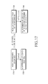
- FIG. 12 illustrates an E-PDCCH multiplexing structure where A-UEs decode a PCFICH to determine an actual PDCCH size and a first E-PDCCH symbol, according to an embodiment of the present invention.
- a PDCCH transmission 1210 has 2 OFDM symbols.
- the first E-PDCCH symbol is the third OFDM symbol, which is the first OFDM symbol after the PDCCH transmission.
- the E-PCFICH transmission (not shown) is always in the first E-PDCCH symbol and, in the structure illustrated in FIG. 12 , it indicates that the E-PDCCH is transmitted in 2 OFDM symbols 1220.
- the E-PDCCH transmission PRBs 1230 are predetermined.
- E-PDCCH E-PDCCH CCEs
- all E-PDCCH CCEs are jointly considered for all Scells, instead of having a separate set of CCEs for each Scell. Therefore, there is only a single set of CCEs in the E-PDCCH, where each SUE may have its UE-CSS and its UE-DSS. This also enables the transmission of a single E-PCFICH, instead of multiple E-PCFICH with each one corresponding to a different Scell in the E-PDCCH.
- the UE-CSS for S-UEs is separately configured and its size, in number of CCEs, may be broadcasted by the Node B.
- the UE-CSS size may take one of four predetermined values and the Node B broadcasts 2 bits to indicate that value (for example, through an SIB in the Pcell) or to indicate that the UE-CSS size is either 1, 2, 3, or 4 times a basic size of K CCEs.
- the CCEs for the UE-CSS in the E-PDCCH are placed first, i.e., before the CCEs for the UE-DSS. Once an S-UE is informed of the UE-CSS size, it needs to determine the CCEs corresponding to each Scell.
- the S-UE is informed of the order of Scells either through higher layer signaling, for UE-specific CI configuration, or as part of the system information for cell-specific CI configuration. This is equivalent to an S-UE being informed of the CI value for its DCI formats.
- the order may be in terms of decreasing BWs, e.g., the larger BWs are ordered first.
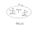
- FIG. 13 is a diagram illustrating an assignment of different CI values to different cells, according to an embodiment of the present invention.
- the CCEs for the UE-CSS of the macro-cell 1310 are placed in the PDCCH.
- the CCEs of the UE-CSS of S-UEs are placed in the same order in the logical domain.
- FIG. 14 is a diagram illustrating placement of CCEs for multiple UE-CSS, according to an embodiment of the present invention.
- the placement of the CCEs for the UE-DSS 1430 occurs after the placement of the CCEs for the UE-CSS in the logical domain.
- the CCEs for the UE-CSS of S-UEs are ordered as illustrated in FIG. 14 to reduce the associated number of Blind Decoding Operations (BDOs) because, for each UE-CSS, an S-UE searches a sub-set of the total set of CCEs allocated to the total UE-CSS. Moreover, by ordering the UE-CSSs for S-UEs, it is not necessary to include the CI IE in DCI formats transmitted in each UE-CSS.
- BDOs Blind Decoding Operations
- the ordering of individual UE-CSS for S-UEs is not applied and the respective CCEs may be distributed over the entire set of CCEs for the total UE-CSS. Thereafter, CI inclusion in the DCI formats is performed and the UE search process for DCI formats can be performed for the UE-DSS of S-UEs as will be described below.
- the UE-CSS remains unchanged, the S-UEs are treated as P-UEs with respect to the transmission of DCI format 3 and DCI format 1C in Scells, and there is no differentiation of UEs into different categories with respect to the UE-CSS.
- the PCH can be transmitted to all S-UEs in the cell with the PDCCH transmission (Pcell).
- S-UEs acquire the synchronization signal of the cell (such as a macro-cell) with PDCCH transmission (Pcell). Thereafter, the RACH process is completed through the Pcell and no additional RACH response signaling, corresponding to cells without PDCCH transmission (Scells), is necessary.
- the SIBs for cells (such as micro-cells) without PDCCH transmission (Scells) can also be transmitted from the cell (such as macro-cell) with PDCCH transmission (Pcell) using different CRC masks in DCI format 1C to indicate the cell corresponding to the SIB transmission.
- DCI format 3 multiplexes TPC commands corresponding to UEs in the cell (such as a macro-cell) with PDCCH transmission (Pcell) and to UEs in the cells (such as micro-cells) without PDCCH transmission (Scells).
- P-UEs have their UE-CSS for DCI format transmission in the PDCCH as in a backward compatible system including a single cell.
- UE-CSS For S-UEs, either a new UE-CSS is defined in the E-PDCCH, as described above in the first alternative, or no additional UE-CSS is defined and all UEs (P-UEs and S-UEs) use the same UE-CSS in the PDCCH, as described above in the second alternative.
- Equation (2) For the UE-DSS and single-cell operation, using the previously defined notation, the CCEs corresponding to a PDCCH candidate m are given by Equation (2).
- S k L L ⁇ Y k + m ⁇ mod ⁇ N CCE , k / L ⁇ + i
- the above UE-DSS structure leads to identical UE-DSSs for different cells (Pcell or Scells) as they are assumed to share the same UE-DSS in the E-PDCCH (or in the PDCCH when it supports the transmission of DCI formats for multiple cells).
- the UE-DSS also depends on the Cell_ID. This can substantially decrease the probability that a DCI format transmission is blocked due to the unavailability of CCEs in the UE-DSS. Reducing this blocking probability increases the probability that a PDSCH or PUSCH scheduling occurs and therefore, improves the respective DL or UL system throughput and enhances operating quality and reliability.
- the Cell_ID may be the CI value allocated to each cell.
- the UE may be informed of the Cell_ID through higher layer signaling. At least when the cells have equal BWs (and a respective CI is defined), the Cell_ID may be the same as the respective CI.
- the UE may obtain the Cell_ID during initial synchronization with the respective cell, or if the cell does not transmit synchronization signals, the UE may obtain the respective Cell_ID through higher layer signaling from the cell transmitting synchronization signals after synchronization. Additionally, the Cell_ID may be UE-specific and informed to each UE through higher layer signaling.
- the Cell_ID for each UE can depend on the number of cells the UE is configured for. If UE1 is configured for Cell1 and Cell2, the respective Cell_IDs can be Cell_ID1 and Cell_ID2. If UE2 is configured for Cell2 and Ce113, the respective Cell_IDs can also be Cell_ID1 and Cell_ID2.
- the following example further demonstrates the occurrence of transmission blocking for a DCI format.
- DCI formats to a UE are transmitted with 4 CCEs, then, as there are only 2 candidates in the UE-DSS for this CCE aggregation level, transmission of DCI formats for at most 2 cells can be supported (or one cell, for both PDSCH reception and PUSCH transmission).
- the UE-DSSs for different UEs may have overlapping CCEs, and for this reason it will often be likely that the transmission of a DCI format for only a single cell can be supported.
- An embodiment of the invention to construct separate UE-DSS for each cell considers that the initialization of the variable Y k includes the Cell_ID.
- Y k includes the Cell_ID.
- ⁇ denotes the binary modulo add operation
- an A-UE receives multiple PDSCH or transmits multiple PUSCH in multiple cells while the respective DCI formats are transmitted in a single cell
- Y -1 ( UE_ID ) ⁇ ( Cell _ ID ) ⁇ 0 for the UE-DSS of the respective cell.
- FIG. 15 illustrates an initialization of a variable Y k with a Cell_ID according to an embodiment of the present invention.
- the binary UE_ID 1510 and the binary Cell_ID 1520 are added by a binary adder 1530 to provide the initial value Y -1 1540 of the variable Y k , randomizing the CCEs in the UE-DSS in sub-frame k for DCI formats corresponding to the respective cell.
- each UE-DSS can be obtained by Equation (3).
- S k , c L L ⁇ Y k + m + f c ⁇ mod ⁇ N CCE , k / L ⁇ + i
- the transmission of DCI formats for scheduling in multiple Scells increases the number of BDOs an A-UE performs. Without any restrictions in the locations of these possible DCI formats, this increase in the number of BDOs is linear with the number of Scells. This increases the UE receiver complexity and also increases the probability of a false CRC test (resulting to a UE incorrectly considering a DCI format as intended for it).
- the UE After the UE identifies a PDCCH for cell c 1 , it performs a number additional BDOs equal to the number of possible aggregation levels to determine if it also has a PDCCH for cell c 2 .
- this number of additional BDOs is 4, as the possible aggregation levels are ⁇ 1,2,4,8 ⁇ . This process can directly extend to additional cells.
- a third design is a combination of the first and second designs, where the aggregation level used for the PDCCH in a reference cell (Pcell) affects the possible aggregation levels for the PDCCH for the remaining cells (Scells) for which a UE is configured.
- the position of the PDCCH for the reference cell affects the possible PDCCH positions for the remaining cells.
- PDCCH extension was compatible with existing single-cell communications.
- PDCCH extension may also be supported in a non-compatible manner.
- a different interpretation of the PCFICH values and a different configuration of the UE-CSS and UE-DSS may apply.
- the PCFICH for non-compatible PDCCH extension can convey more values, which are not predetermined but can semi-statically vary.
- the Node B may broadcast a configuration of PDCCH sizes, from a set of possible configurations, and the PCFICH may then simply indicate one size from the broadcasted configuration of PDCCH sizes.
- the Node B may indicate one of the ⁇ 1, 2, 3, 4 ⁇ , ⁇ 2, 3, 4, 5 ⁇ , ⁇ 3, 4, 5, 6 ⁇ and ⁇ 4, 5, 6, 7 ⁇ , in number of OFDM symbols, for the PDCCH size configuration.
- the 2 bits in the PCFICH can then be used to inform the UEs of the PDCCH size within the configuration broadcasted by the Node B.
- FIG. 16 illustrates a PDCCH size extension by configuring a set of possible values and using a PCFICH to indicate one value in the set, according to an embodiment of the present invention.
- the Node B broadcasts 2 bits, for example, "10", to indicate the PDCCH size configuration of ⁇ 3, 4, 5, 6 ⁇ symbols 1610.
- the PCFICH transmitted in each sub-frame indicates an element from the PDCCH size configuration set, such as, for example, the third element 1620.
- the UE determines the PDCCH size based on both the broadcasted PDCCH size configuration and the PCFICH value 1630.
- an individual size of the UE-CSS or UE-DSS can also be configured.
- the Node B may broadcast the UE-CSS size. Consequently, A-UEs can know that the UE-CSS size may have one of four predetermined values and the Node B simply broadcasts 2 bits to indicate that value or to indicate that the UE-CSS size is 1, 2, 3, or 4 times the basic UE-CSS size of 16 CCEs.
- the indication of the UE-CSS size may also be implicit based on the PDCCH configuration size. For example, if the Node B broadcasts the third PDCCH configuration size in FIG.
- A-UEs can identify that the UE-CSS is 3 times the basic UE-CSS size of 16-CCEs, i.e., the UE-CSS size is 48 CCEs or it is determined by the third element in a configured set of UE-CSS sizes such as, for example, a set of ⁇ 16, 28, 36, 44 ⁇ CCEs.
- FIG. 17 illustrates explicit and implicit indication by the Node B of a UE-CSS size to A-UEs, according to an embodiment of the present invention.
- the Node B informs A-UEs of the UE-CSS size through a broadcast channel, e.g., an SIB transmission.
- a broadcast channel e.g., an SIB transmission.
- the Node B transmits 2 bits with a value "10" to indicate 36 CCEs, which is the third element in a set of 4 possible UE-CSS sizes 1710.
- A-UEs upon reception of that broadcast information, determine the UE-CSS for each cell 1720, as described above, for PDCCH extension compatible with legacy systems.
- the Node B broadcasts the PDCCH size configuration (for example, in an SIB), as described in FIG.
- A-UEs determine the UE-CSS size and the UE-CSS for each cell.
- the Node B may broadcast the third PDCCH size configuration 1730 and the then A-UEs determine the UE-CSS size to be 36 CCEs 1740.
Abstract
Description
- The present invention is directed to wireless communication systems and, more specifically, to extending a Physical Downlink Control CHannel (PDCCH) from supporting communication in a single cell to supporting communication in multiple cells.
- A communication system includes a DownLink (DL) that supports the transmissions of signals from a Base Station (BS) (or Node B) to User Equipments (UEs), and an UpLink (UL) that supports transmissions of signals from UEs to the Node B. A UE, also commonly referred to as a terminal or a mobile station, may be fixed or mobile and may be a wireless device, a cellular phone, a personal computer device, etc. A Node B is generally a fixed station and may also be referred to as a Base Transceiver System (BTS), an access point, or some other similar terminology.
- The DL signals include data signals that carry information content, control signals, and Reference Signals (RS), which are also known as pilot signals. The Node B transmits data information to a UE through a Physical Downlink Shared CHannel (PDSCH) and transmits control information to a UE through a PDCCH.
- The UL signals also include data signals, control signals, and RSs. A UE transmits data information to the Node B through a Physical Uplink Shared CHannel (PUSCH) and transmits control information through a Physical Uplink Control CHannel (PUCCH). It is also possible for UEs to transmit control information through the PUSCH.
- Downlink Control Information (DCI) serves several purposes and is transmitted in DCI formats through the PDCCH. For example, DCI formats are used to provide DL Scheduling Assignments (SAs) for PDSCH receptions by the UEs, UL SAs for PUSCH transmissions by the UEs, or Transmission Power Control (TPC) commands for PUSCH receptions or PUCCH transmissions from the UEs. DCI formats also provide scheduling information for a Paging CHannel (PCH), for a response by the Node B to Random Access CHannels (RACH) transmitted by the UEs, and for Secondary Information Blocks (SIBs) providing broadcast control information from the Node B. The DCI format for transmitting the TPC commands will be referred to as
DCI format 3 and the DCI format for transmitting the scheduling information for the transmission of either PCH, RACH response, or SIBs will be referred to as DCI format 1C. - Typically, the PDCCH is a major part of the total DL overhead and directly impacts the achievable DL cell throughput. A conventional method for reducing PDCCH overhead is to scale its size according to the resources required to transmit the DCI formats during a DL Transmission Time Interval (TTI). Assuming Orthogonal Frequency Division Multiple Access (OFDMA) as the DL transmission method, a Control Channel Format Indicator (CCFI) parameter transmitted through the Physical Control Format Indicator CHannel (PCFICH) can be used to indicate the number of OFDM symbols occupied by the PDCCH.
-
FIG. 1 is a diagram illustrating a structure for the PDCCH transmission in the DL TTI, which for simplicity includes one sub-frame having M OFDM symbols. - Referring to
FIG. 1 , the PDCCH occupies thefirst N symbols 110. The remaining M-N symbols of the sub-frame are assumed to be primarily used forPDSCH transmission 120. The PCFICH 130 is transmitted in some sub-carriers, also referred to as Resource Elements (REs), of the first symbol. The PCFICH includes 2 bits indicating a PDCCH size of M=1, M=2, or M=3 OFDM symbols. Additionally, some sub-frame symbols include RS REs, 140 and 150, which are common to all UEs for each of the Node B transmitter antennas, which inFIG. 1 are assumed to be two. The RSs enable a UE to obtain a channel estimate for its DL channel medium and to perform various other measurements and functions. The PDSCH typically occupies theremaining REs 160. - Additional control channels may be transmitted in the PDCCH region but, for brevity, they are not illustrated in
FIG. 1 . For example, to support Hybrid Automatic Repeat reQuest (HARQ) for PUSCH transmissions, a Physical Hybrid-HARQ Indicator CHannel (PHICH) may be transmitted by the Node B, in a similar manner as the PCFICH, to indicate to groups of UEs whether or not their previous PUSCH transmission was received by the Node B. - The Node B separately codes and transmits each DCI format through a PDCCH.
-
FIG. 2 is a block diagram illustrating a conventional processing chain for transmitting a DCI format. - Referring to
FIG. 2 , the Medium Access Control (MAC) layer IDentity of the UE (or UE ID), for which a DCI format is intended, masks the Cyclic Redundancy Check (CRC) of the DCI format codeword in order to enable the reference UE to identify that the particular DCI format is intended for the reference UE. The CRC 220 of the (non-coded)DCI format bits 210 is computed and is subsequently masked 230 using the exclusive OR (XOR) operation between CRC bits and theUE ID 240, i.e., XOR(O,O) = 0, XOR(0,1) = 1, XOR(1,0) = 1, and XOR(1,1) = 0. - The masked CRC is then appended to the
DCI format bits 250,channel coding 260 is performed, for example, using a convolutional code, followed by rate matching 270 to the allocated PDCCH resources, and then interleaving andmodulation 280. Thereafter, acontrol signal 290 is transmitted. - A UE receiver performs the reverse operations of the Node B transmitter to determine whether a DCI format in the PDCCH was intended for the UE.
-
FIG. 3 is a block diagram illustrating a conventional processing chain for receiving a DCI format. - Referring to
FIG. 3 , a received control signal, i.e., a PDCCH, 310 is demodulated and the resulting bits are de-interleaved 320. Rate matching applied in the Node B transmitter is restored 330, and the output is subsequently decoded 340. After decoding, theDCI format bits 360 are obtained, after extracting the CRC bits 350, which are then de-masked 370 by applying the XOR operation with theUE ID 380. Thereafter, the UE performs a CRCtest 390. If the CRC test passes, the UE considers the DCI format as being valid and determines the parameters for PDSCH reception (DL DCI format) or PUSCH transmission (UL DCI format). If the CRC test does not pass, the UE disregards the DCI format. - The information bits of the DCI format correspond to several Information Elements (IEs) such as, for example, the Resource Allocation (RA) IE indicating the part of the operating BandWidth (BW) allocated to a UE for PDSCH reception or PUSCH transmission, the Modulation and Coding Scheme (MCS) IE, the IE related to the HARQ operation, etc. The BW unit for PDSCH or PUSCH transmissions is assumed to consist of several REs, e.g., 12 REs, and will be referred to as a Physical Resource Block (PRB).
- PDCCHs for a UE are not transmitted at fixed and predetermined locations and do not have predetermined coding rate. Consequently, a UE performs multiple PDCCH decoding operations in each sub-frame to determine whether any of the PDCCHs transmitted by the Node B is intended for the UE. In order to assist UEs with the multiple PDCCH decoding operations, the PDCCH REs are grouped into Control Channel Elements (CCEs) in the logical domain. For a given number of DCI format bits as illustrated in
FIG. 2 , the number of CCEs for the respective PDCCH transmission depends on the channel coding rate. For UEs experiencing low or high Signal-to-Interference and Noise Ratio (SINR) in the DL, the Node B may respectively use a low or high channel coding rate in order to achieve a desired PDCCH BLock Error Rate (BLER). Therefore, a PDCCH transmission to a UE experiencing low DL SINR typically requires more CCEs that a PDCCH transmission to a UE experiencing high DL SINR. Alternatively, different power boosting of CCE REs may also be used in order to achieve a target BLER. Typical CCE aggregation levels for PDCCH transmissions are assumed to follow a "tree-based" structure, for example, 1, 2, 4, and 8 CCEs. - For the PDCCH decoding process, a UE may determine a search space for a candidate PDCCH, after it restores the CCEs in the logical domain, according to a common set of CCEs for all UEs in a UE-Common Search Space (UE-CSS) and according to a UE-specific set of CCEs in a UE-Dedicated Search Space (UE-DSS). The UE-CSS includes the first C CCEs in the logical domain. The UE-DSS may be determined according to a pseudo-random function having UE-common parameters as inputs, such as the sub-frame number or the total number of PDCCH CCEs in the sub-frame, and UE-specific parameters such as the identity assigned to a UE (UE_ID).
- For example, for CCE aggregation levels L∈ {1,2,4,8}, the CCEs corresponding to PDCCH candidate m can be given by Equation (1).

- In Equation (1), N CCE,k is a total number of CCEs in sub-frame k , i=0,···, L-1 , m=0,···,M (L)-1, and M (L) is a number of PDCCH candidates for the respective CCE aggregation levels. Exemplary values of M (L) for L∈ {1,2,4,8} are, respectively, {6, 6, 2, 2}. For the UE-CSS, Yk =0 . For the UE-DSS, Yk =(A·Y k-1)modD where, for example, Y -1 = UE_ID ≠ 0, A = 39827 and D = 65537.
- DCI formats conveying information to multiple UEs, such as
DCI format 3 or DCI format 1C, are transmitted in the UE-CSS. If enough CCEs remain after transmittingDCI formats 3 and 1C, the UE-CSS may also convey some DCI formats for PDSCH receptions or PUSCH transmissions by UEs. The UE-DSS exclusively conveys DCI formats for PDSCH receptions or PUSCH transmissions. In an exemplary setup, the UE-CSS includes 16 CCEs and supports 2 PDCCH with L = 8 CCEs, or 4 PDCCH with L = 4 CCEs, or 1 PDCCH with L = 8 CCEs and 2 PDCCH with L = 4 CCEs. The CCEs for the UE-CSS are placed first in the logical domain (prior to interleaving). -
FIG. 4 illustrates a conventional PDCCH transmission process. After channel coding and rate matching, as illustrated inFIG. 2 , the encoded DCI format bits are mapped to CCEs in the logical domain. - Referring to
FIG. 4 , the first 4 CCEs (L=4),CCE1 401,CCE2 402,CCE3 403, andCCE4 404 are used for DCI format transmission to UE1. The next 2 CCEs (L=2),CCE5 411 andCCE6 412, are used for DCI format transmission to UE2. The next 2 CCEs (L=2),CCE7 421 andCCE8 422, are used for DCI format transmission to UE3. The last CCE (L=1),CCE9 431, is used for DCI format transmission to UE4. - The DCI format bits may be scrambled 440 using a binary scrambling code, which is typically cell-specific, and are subsequently modulated 450. Each CCE is further divided into mini-CCEs. For example, a CCE including 36 REs can be divided into 9 mini-CCEs, each having 4 REs.
- Interleaving 460 is applied among mini-CCEs (blocks of 4 QPSK symbols). For example, a block interleaver may be used where the interleaving is performed on symbol-quadruplets (4 Quadrature Phase Shift Keying (QPSK) symbols corresponding to the 4 REs of a mini-CCE) instead of on individual bits. After interleaving the mini-CCEs, the resulting series of QPSK symbols may be shifted by
J symbols 470, and then each QPSK symbol is mapped to anRE 480 in the PDCCH region of the DL sub-frame. Therefore, in addition to the RS from the Node B transmitter antennas, 491 and 492, and other control channels such as thePCFICH 493 and the PHICH (not shown), the REs in the PDCCH include QPSK symbols corresponding to DCI format forUE1 494,UE2 495,UE3 496, andUE4 497. - In order to support higher data rates and signal transmission in BWs larger than the BWs of individual carriers (or cells) supporting legacy communications, aggregation of multiple carriers (or cells) can be used. For example, to support communication over 100 MHz, aggregation of five 20 MHz carriers (or cells) can be used. For ease of description, UEs that can only operate over a single carrier (or cell) will be referred to herein as Legacy-UEs (L-UEs) while UEs that can operate over multiple carriers (or cells) will be referred to herein as Advanced-UEs (A-UEs).
-
FIG. 5 illustrates a principle of carrier aggregation. An operating BW of 100 MHz includes the aggregation of 5 (contiguous, for simplicity) carriers, 521, 522, 523, 524, and 525, each having a BW of 20 MHz. Similarly to the sub-frame structure for communication over a single carrier inFIG. 1 , the sub-frame structure for communication over multiple carriers includes a PDCCH region, for example, 531 through 535, and a PDSCH region, for example, 541 and 545. -
FIG. 6 is a diagram illustrating a conventional heterogeneous network deployment. - Referring to
FIG. 6 , an area covered by amacro-Node B 610 encompasses areas covered bymicro-Node Bs FIG. 6 , the signals transmitted by a macro-Node B can cause severe interference to the signals transmitted by a micro-Node B. Interference coordination techniques can be applied to PDSCH transmissions to mitigate macro-to-micro interference using different PRBs between PDSCH signal transmissions from the macro-Node B and a micro-Node B. However, such interference coordination is not possible for the PDCCH because the CCEs are pseudo-randomly distributed over the entire operating BW, as was previously described. - To avoid interference to PDCCH transmissions in a micro-cell, all PDCCH transmissions can be in the macro-cell and a Carrier Indicator, or Cell Indicator, (CI) IE can be introduced in the DCI formats to indicate whether the DCI format is for the macro-cell or for the micro-cell. For example, a CI IE of 2 bits can indicate whether the DCI format is for the macro-cell or for any of a maximum of three micro-cells.
- In addition to providing PDCCH interference avoidance, PDCCH transmission in certain cells may be avoided for practical reasons. For example, it is desirable to avoid PDCCH transmissions in cells with small BW as they are inefficient and lead to large respective overhead. Also, PDSCH transmissions in a cell can be optimized to occur over all DL sub-frame symbols if transmissions of PDCCH and of other supporting signals such as UE-common RS, are avoided.
- The CI functionality can accommodate:
- PUSCH scheduling in the UL of multiple cells through PDCCH transmission in a single cell;
- PDSCH scheduling in the DL of multiple cells through PDCCH transmission in a single cell; and
- PDCCH transmission in a first cell (macro-cell) and in a second cell (micro-cell).
-
FIG. 7 is a diagram illustrating a conventional PUSCH scheduling in the UL of multiple cells through PDCCH transmission in a single cell. - Referring to
FIG. 7 , a PDCCH in asingle cell 710 is associated with the UL of two cells, 720 and 730. Consequently, PDCCHs scheduling PUSCH transmissions fromCell 1 andCell 2 are transmitted in a single cell and the cell of PUSCH transmission can be identified by a CI IE consisting of 1 bit. -
FIG. 8 is a diagram illustrating a conventional PDSCH scheduling in a DL of multiple cells through PDCCH transmission in a single cell. - Referring to
FIG. 8 , onlyCell1 810 andCell3 830 transmit PDCCH. Scheduling forCell2 820 is performed through PDCCH transmission in Cell1 and scheduling forCell4 840 andCell5 850 is performed through PDCCH transmissions in Cell3. -
FIG. 9 is a diagram illustrating a conventional PDCCH transmission in a first cell (macro-cell) and in a second cell (micro-cell), which may occur to avoid interference in PDCCH transmissions between a macro-cell and a micro-cell. - Referring to
FIG. 9 , although both macro-cell and micro-cell may have PDSCH transmissions inCell1 910 andCell2 920, the macro-cell transmits PDCCH only in Cell1 and the micro-cell transmit PDCCH only in Cell2. - One issue for supporting PDCCH transmissions using a CI is the PDCCH size. In communication systems having a single cell, the PDCCH is assumed to be limited to a maximum number of M OFDM symbols. In communication systems having multiple cells and having PDCCH transmission in a single cell, this limitation of the PDCCH size may cause scheduling restrictions. In general, the PDCCH size may need to be increased if the PDCCH in one cell performs scheduling in multiple cells.
- For the UE-CSS, which is assumed to include a fixed number of CCEs, it may not be possible to transmit additional PDCCH corresponding to additional cells.
- For the UE-DSS, modification and expansion is needed in order to transmit multiple DCI formats to a UE in the PDCCH region of a single cell.
- For the blind decoding operations a UE needs to perform, their number may scale linearly with the number of cells for which PDCCH is transmitted in a single cell. It is desirable to avoid such an increase in order to avoid the associated impact on the UE receiver complexity.
- Therefore, there is a need to expand the PDCCH region in a single cell to support PDCCH transmissions for scheduling in multiple cells.
- There is a further need to expand the UE-CSS in a single cell to enable PDCCH transmission conveying UE-common information for multiple cells.
- There is another need to expand the capacity of the UE-DSS in a single cell for scheduling over multiple cells.
- Additionally, there is another need to reduce the number of blind decoding operations a UE needs to perform.
- Accordingly, the present invention has been designed to solve at least the aforementioned limitations and problems in the prior art and to provide the following advantages. An aspect of the present invention is to provide methods and apparatus for expanding a control region in a single cell from supporting transmission of DCI to a UE for communication over the single cell to supporting transmission of DCI to the UE for communication over multiple cells.
- In accordance with another aspect of the present invention, a conventional control region in a single cell, including a UE-CSS and a UE-DSS and supporting DCI transmission for the single cell, is expanded to support DCI transmission for multiple cells by including either multiple UE-CSS, each multiple UE-CSS corresponding to each of the multiple cells, or multiple UE-DSS, each multiple UE-DSS corresponding to each of the multiple cells, or both.
- In accordance with another aspect of the present invention, support of DCI transmission for multiple cells, each having a Cell Identity (Cell_ID), through a control region in a single cell is provided by informing the UE of the Cell_ID for each of the multiple cells and then defining a distinct UE-DSS for each of the multiple cells in the control region of the single cell, where each distinct UE-DSS has the same structure as the UE-DSS for DCI transmission over only the single cell and its location additionally depends only on the respective Cell_ID. The DCI is conveyed through DCI formats and DCI formats in each UE-DSS may include a CI IE that is derived from the Cell_ID.
- In accordance with another aspect of the present invention, support of DCI transmission for multiple cells through a control region in a primary cell is provided by defining a first control region for DCI transmission corresponding to a first set of cells that includes the primary cell, and a second control region for DCI transmission corresponding to a second set of cells including the multiple cells that are not in the first set of cells. The first control region includes the same resources as the control region for DCI transmission only in the primary cell. The second control region includes resources that would otherwise be used for data transmission in the primary cell.
- The above and other aspects, features, and advantages of the present invention will be more apparent from the following detailed description taken in conjunction with the accompanying drawings, in which:
-
FIG. 1 is a diagram illustrating a conventional structure for PDCCH transmission; -
FIG. 2 is a block diagram illustrating a conventional processing chain for transmitting a DCI format; -
FIG. 3 is a block diagram illustrating a conventional processing chain for receiving a DCI format; -
FIG. 4 is a diagram illustrating a conventional PDCCH transmission process; -
FIG. 5 is a diagram illustrating a principle of carrier aggregation; -
FIG. 6 is a diagram illustrating a conventional heterogeneous network deployment; -
FIG. 7 is a diagram illustrating a conventional PUSCH scheduling in a UL of multiple cells through PDCCH transmission in a single cell; -
FIG. 8 is a diagram illustrating a conventional PDSCH scheduling in a DL of multiple cells through PDCCH transmission in a single cell; -
FIG. 9 is a diagram illustrating a conventional PDCCH transmission in a first cell (macro-cell) and in a second cell (micro-cell); -
FIG. 10 is a diagram illustrating a method of informing an A-UE whether a CI IE is included in DCI formats in a UE-specific manner, according to an embodiment of the present invention; -
FIG. 11 is a diagram illustrating an E-PDCCH multiplexing structure where A-UEs assume a maximum PDCCH size to determine a first E-PDCCH symbol, according to an embodiment of the present invention; -
FIG. 12 is a diagram illustrating an E-PDCCH multiplexing structure where A-UEs decode a PCFICH to determine an actual PDCCH size and a first E-PDCCH symbol, according to an embodiment of the present invention; -
FIG. 13 is a diagram illustrating an assignment of different CI values to different cells, according to an embodiment of the present invention; -
FIG. 14 is a diagram illustrating placement of CCEs for multiple UE-CSS, according to an embodiment of the present invention; -
FIG. 15 is a diagram illustrating an operation for generating a distinct UE-DSS for each cell through a respective distinct initialization of a variable determining the location of a UE-DSS, according to an embodiment of the present invention; -
FIG. 16 is a diagram illustrating an extension of a PDCCH size by configuring a set of possible values and using a PCFICH to indicate one value in the set, according to an embodiment of the present invention; and -
FIG. 17 is a diagram illustrating a combination of explicit and implicit indication by a Node B of a UE-CSS size, according to an embodiment of the present invention. - Various embodiments of the present invention will now be described in detail with reference to the accompanying drawings. This invention may, however, be embodied in many different forms and should not be construed as limited to the embodiments set forth herein. Rather, these embodiments are provided so that this disclosure will be thorough and complete and will fully convey the scope of the invention to those skilled in the art.
- Additionally, although the present invention is described in relation to an Orthogonal Frequency Division Multiple Access (OFDMA) communication system, it also applies to Frequency Division Multiplexing (FDM) systems and to Single-Carrier Frequency Division Multiple Access (SC-FDMA), OFDM, FDMA, Discrete Fourier Transform (DFT)-spread OFDM, DFT-spread OFDMA, SC-OFDMA, and SC-OFDM.
- In accordance with an embodiment of the present invention, an A-UE is semi-statically configured, for example, through Radio Resource Control (RRC) signaling, the cells over which it may have PDSCH reception or PUSCH transmission. A link between the DL and the UL in those cells may also be configured. The inclusion of the CI IE in DCI formats can be either UE-specific or cell-specific. When the CI IE in DCI formats is UE-specific, each A-UE is informed through higher layer signaling (MAC or RRC signaling) whether its assigned DCI formats in a cell include a CI IE. When the CI IE in DCI formats is cell-specific, the Node B may broadcast whether a CI IE is included in the DCI formats. In both cases, the values of the CI to be monitored by an A-UE are also included. The DCI formats having the CI IE may be all DCI formats or a predetermined subset of DCI formats. For example, DCI formats in the UE-CSS may not contain CI while DCI formats in the UE-DSS may contain CI.
-
FIG. 10 is a diagram illustrating a method of informing an A-UE whether a CI IE is included in DCI formats in a UE-specific manner, according to an embodiment of the present invention. - Referring to
FIG. 10 , an A-UE is configured in the DL ofCell1 1010,Cell2 1020, andCell3 1030 for PDSCH reception and in the UL ofCell1 1040 andCell2 1050 for PUSCH transmission. The cells of PDCCH transmission are also informed to the A-UE through higher layer signaling. - In
FIG. 10 , a PDCCH is transmitted only inCell1 1060. For example, the DL and UL for Cell1 may correspond to a macro-cell, while the DL and UL of Cell2 may correspond to a first micro-cell and the DL of Cell3, and the UL of Cell2 can correspond to a second micro-cell. DCI formats associated with PUSCH transmissions or with TPC for PUSCH or PUCCH transmissions (DCI format 3) will be referred to as UL DCI formats. The remaining DCI formats are associated with PDSCH receptions and will be referred to as DL DCI formats. - For the setup in
FIG. 10 , DL DCI formats to the UE include a CI IE having 2 bits. For example, for the DL, the CI values of '00', '01", and "10" can correspond to Cell1, Cell2, and Cell3, respectively, while the CI value "11" is unused. Similarly, for the UL, the CI values of '0' and "1" can correspond to Cell1 and Cell2, respectively. In general, the number of bits for the CI IE can be different between DL DCI formats and UL DCI formats (including, for example, not having any CI IE bits in UL DCI formats while having CI IE bits in DL DCI formats). The association between CI values and Cells may also be implicitly determined. For example, ascending CI values of "00", "01", "10", and "11" can be mapped to Cells in order of increasing carrier frequency. - The use of CI to indicate the cell for which a DCI format is intended may not be necessary for cells with different BWs because the respective DCI formats may have different sizes. For example, for 2 cells, where the PDCCH is transmitted only in one cell, the CI inclusion in the DL DCI formats is not necessary if, for example, one cell has a BW of 20 MHz and the other cell has a BW of 5 MHz. In general, the primary reason for having a different DCI format size for different BWs is the Resource Allocation (RA) IE in the DCI formats, which should have a larger size for cells with larger BWs, as it addresses a larger number of PRBs.
- The transmission of DCI formats to L-UEs is supported with the conventional PDCCH structure. The PDCCH transmission to A-UEs having PDSCH reception or PUSCH transmission in the same cell is also supported with the conventional PDCCH structure. There is no differentiation between these A-UEs and the L-UEs with respect to the PDCCH transmission, although different DCI formats may be used. For ease of reference, such A-UEs will be referred to as Primary-UEs (P-UEs) and the cell with the PDCCH transmission as Primary-cell (Pcell). Conversely, A-UEs having PDSCH reception or PUSCH transmission in a cell other than the Pcell will be referred to as Secondary-UEs (S-UEs) and the corresponding cells as Secondary-cells (Scells).
- For example, in
FIG. 10 , UEs receiving PDSCH in Cell1 are P-UEs and Cell1 is the Pcell, while UEs receiving PDSCH in Cell2 are S-UEs and Cell2 is a Scell. An A-UE can be both a P-UE and an S-UE depending on the cell (Pcell or Scell, respectively). Therefore, the classification of an A-UE as a P-UE or an S-UE is unique for each cell and may be different among cells as an A-UE can be a P-UE in the Pcell and the S-UE in an Scell. - For the PDCCH transmission to S-UEs in Scells, the conventional PDCCH structure or a separate PDCCH structure may be used. For example, for lightly loaded systems for which the capacity (first M OFDM symbols of the DL sub-frame) of the conventional PDCCH structure is not reached for scheduling P-UEs, it is also possible to support the transmission of DCI formats to S-UEs while, for heavily loaded systems, an additional PDCCH structure may be needed to support the PDCCH transmission to S-UEs.
- Whether the conventional PDCCH structure or an Extended PDCCH (E-PDCCH) structure is used can be predetermined or be informed by the Node B through broadcast signaling or through UE-specific higher layer signaling. The PDCCH CCEs for an A-UE can be either in the PDCCH or in the E-PDCCH, but not in both. Whether an A-UE monitors the PDCCH or the E-PDCCH for scheduling a PDSCH or a PUSCH in a specific cell can be semi-statically configured either through higher layer signaling or through broadcast signaling.
- If the E-PDCCH in the Pcell is used for scheduling a PDSCH or a PUSCH in Scells, the following is considered, in accordance with an embodiment of the present invention:
- The E-PDCCH provides an extension to the PDCCH and therefore, conveys information of the same nature. In addition to DCI formats for S-UEs, the E-PDCCH may include a respective PCFICH (referred to as an E-PCFICH) and a PHICH (referred to as an E-PHICH) for PUSCH transmissions in Scells served by the E-PDCCH. The E-PCFICH and the E-PHICH have the same structure as the PCFICH and the PHICH, respectively.
- The DCI formats in the E-PDCCH are transmitted in CCEs, but the CCE allocation is in PRBs as the E-PDCCH is orthogonally multiplexed with the PDSCH. The PRBs for the E-PDCCH can be semi-statically or dynamically configured. A semi-static configuration of E-PDCCH PRBs ensures adequate separation in the frequency domain in order to obtain frequency diversity or that the PRBs are selected according to an interference co-ordination technique minimizing interference from adjacent cells.
- The first E-PDCCH symbol can be the first OFDM symbol after the last actual PDCCH OFDM symbol or the first symbol after the last PDCCH OFDM symbol, assuming the maximum number of PDCCH OFDM symbols. When the first E-PDCCH symbol is the first OFDM symbol after the last actual PDCCH OFDM symbol, S-UEs decode the PCFICH to determine the E-PDCCH start. When the first E-PDCCH symbol is the first symbol after the last PDCCH OFDM symbol assuming the maximum number of PDCCH OFDM symbols, maximum E-PDCCH decoding latency results, but errors from incorrect PCFICH detection, which will lead in PDCCH decoding failure, are avoided.
- The last E-PDCCH symbol can be statically, semi-statically, or dynamically configured. With static configuration, the last E-PDCCH symbol can be, for example, the seventh symbol of the DL sub-frame. With semi-static configuration, the last E-PDCCH symbol can be informed by the Node B through a broadcast channel. With dynamic configuration, the last E-PDCCH symbol can be informed through the E-PCFICH.
- The range of OFDM symbols indicated by the E-PCFICH for the E-PDCCH can be different than the range of OFDM symbols indicated by the PCFICH for the PDCCH. For example, the E-PCFICH may also indicate 0 OFDM symbols for the E-PDCCH in which case the E-PCFICH and the E-PHICH may be transmitted in the PDCCH.
-
FIG. 11 illustrates an E-PDCCH multiplexing structure where A-UEs assume a maximum PDCCH size to determine a first E-PDCCH symbol, according to an embodiment of the present invention. - Referring to
FIG. 11 , thePDCCH transmission 1110 has 2 OFDM symbols, out of a maximum of 3 PDCCH OFDM symbols. The first E-PDCCH symbol is the first OFDM symbol after the PDCCH transmission, assuming the maximum of 3 OFDM symbols. Therefore, the first E-PDCCH symbol is the fourth OFDM symbol of the DL sub-frame. The E-PCFICH transmission (not shown) is always in the first E-PDCCH symbol and, for the structure ofFIG. 11 , it indicates that the E-PDCCH is transmitted in 2OFDM symbols 1120. TheE-PDCCH transmission PRBs 1130 are semi-statically configured through broadcast signaling by the Node B (for example, in an SIB). The E-PDCCH transmission is multiplexed with PDSCH transmissions to various UEs, 1140, 1150, and 1160. PDSCH transmissions to L-UEs may or may not occur in PRBs used for E-PDCCH transmission. As an L-UE cannot be aware of the E-PDCCH existence, if it is assigned PDSCH reception in E-PDCCH PRBs, it will treat such PRBs as PRBs that include a PDSCH. Although this will degrade the PDSCH reception quality for the L-UEs, it is up to the Node B to determine whether or not perform such scheduling. A-UEs can be aware of the E-PDCCH PRBs and apply the appropriate rate matching for their respective PDSCH receptions. -
FIG. 12 illustrates an E-PDCCH multiplexing structure where A-UEs decode a PCFICH to determine an actual PDCCH size and a first E-PDCCH symbol, according to an embodiment of the present invention. - Referring to
FIG. 12 , aPDCCH transmission 1210 has 2 OFDM symbols. The first E-PDCCH symbol is the third OFDM symbol, which is the first OFDM symbol after the PDCCH transmission. The E-PCFICH transmission (not shown) is always in the first E-PDCCH symbol and, in the structure illustrated inFIG. 12 , it indicates that the E-PDCCH is transmitted in 2OFDM symbols 1220. TheE-PDCCH transmission PRBs 1230 are predetermined. - If the transmission of DCI formats for multiple Scells is conveyed through the E-PDCCH, in accordance with an embodiment of the present invention, all E-PDCCH CCEs are jointly considered for all Scells, instead of having a separate set of CCEs for each Scell. Therefore, there is only a single set of CCEs in the E-PDCCH, where each SUE may have its UE-CSS and its UE-DSS. This also enables the transmission of a single E-PCFICH, instead of multiple E-PCFICH with each one corresponding to a different Scell in the E-PDCCH.
- In a first alternative, the UE-CSS for S-UEs is separately configured and its size, in number of CCEs, may be broadcasted by the Node B. For example, the UE-CSS size may take one of four predetermined values and the Node B broadcasts 2 bits to indicate that value (for example, through an SIB in the Pcell) or to indicate that the UE-CSS size is either 1, 2, 3, or 4 times a basic size of K CCEs. The CCEs for the UE-CSS in the E-PDCCH are placed first, i.e., before the CCEs for the UE-DSS. Once an S-UE is informed of the UE-CSS size, it needs to determine the CCEs corresponding to each Scell.
- In a first option for the first alternative, the S-UE is informed of the order of Scells either through higher layer signaling, for UE-specific CI configuration, or as part of the system information for cell-specific CI configuration. This is equivalent to an S-UE being informed of the CI value for its DCI formats. In case a CI may not exist, such as, for example, when the cells have unequal BWs, the order may be in terms of decreasing BWs, e.g., the larger BWs are ordered first.
-
FIG. 13 is a diagram illustrating an assignment of different CI values to different cells, according to an embodiment of the present invention. - Referring to
FIG. 13 , the CCEs for the UE-CSS of the macro-cell 1310 are placed in the PDCCH. The CCEs for the UE-CSS formicro-cell 1 1320 are ordered first in the E-PDCCH (CI = 1) and the CCEs for the UE-CSS formicro-cell 2 1330 are ordered second in the E-PDCCH (CI = 2). Once the CI values have been assigned to Scells, the CCEs of the UE-CSS of S-UEs are placed in the same order in the logical domain. -
FIG. 14 is a diagram illustrating placement of CCEs for multiple UE-CSS, according to an embodiment of the present invention. - Referring to
FIG. 14 , the L1 CCEs for a first UE-CSS of S-UEs (micro-cell 1 or for a first set of S-UEs, CI = 1) are placed first 1410, followed by the L2 CCEs for a second UE-CSS of S-UEs (micro-cell 2 or for a second set of S-UEs, CI = 2) 1420. The placement of the CCEs for the UE-DSS 1430 occurs after the placement of the CCEs for the UE-CSS in the logical domain. The number of CCEs of the UE-CSS for S-UEs for the different CI values, denoted by L1 and L2 inFIG. 14 , may be implicitly determined from the total UE-CSS size or may be informed by the Node B through broadcast signaling. Alternatively, the number of CCEs for the UE-CSS of S-UEs can be the same for all CI values, regardless of the DL or UL operating BW in each Scell (that is, L1 = L2 inFIG. 14 ). - The CCEs for the UE-CSS of S-UEs are ordered as illustrated in
FIG. 14 to reduce the associated number of Blind Decoding Operations (BDOs) because, for each UE-CSS, an S-UE searches a sub-set of the total set of CCEs allocated to the total UE-CSS. Moreover, by ordering the UE-CSSs for S-UEs, it is not necessary to include the CI IE in DCI formats transmitted in each UE-CSS. - In a second option for the first alternative, the ordering of individual UE-CSS for S-UEs is not applied and the respective CCEs may be distributed over the entire set of CCEs for the total UE-CSS. Thereafter, CI inclusion in the DCI formats is performed and the UE search process for DCI formats can be performed for the UE-DSS of S-UEs as will be described below.
- In a second alternative, the UE-CSS remains unchanged, the S-UEs are treated as P-UEs with respect to the transmission of
DCI format 3 and DCI format 1C in Scells, and there is no differentiation of UEs into different categories with respect to the UE-CSS. - The PCH can be transmitted to all S-UEs in the cell with the PDCCH transmission (Pcell).
- Assuming no transmission of synchronization signals from cells (such as micro-cells) without PDCCH transmission (Scells), S-UEs acquire the synchronization signal of the cell (such as a macro-cell) with PDCCH transmission (Pcell). Thereafter, the RACH process is completed through the Pcell and no additional RACH response signaling, corresponding to cells without PDCCH transmission (Scells), is necessary.
- The SIBs for cells (such as micro-cells) without PDCCH transmission (Scells) can also be transmitted from the cell (such as macro-cell) with PDCCH transmission (Pcell) using different CRC masks in DCI format 1C to indicate the cell corresponding to the SIB transmission.
-
DCI format 3 multiplexes TPC commands corresponding to UEs in the cell (such as a macro-cell) with PDCCH transmission (Pcell) and to UEs in the cells (such as micro-cells) without PDCCH transmission (Scells). - Accordingly, P-UEs have their UE-CSS for DCI format transmission in the PDCCH as in a backward compatible system including a single cell. For S-UEs, either a new UE-CSS is defined in the E-PDCCH, as described above in the first alternative, or no additional UE-CSS is defined and all UEs (P-UEs and S-UEs) use the same UE-CSS in the PDCCH, as described above in the second alternative.
- For the UE-DSS and single-cell operation, using the previously defined notation, the CCEs corresponding to a PDCCH candidate m are given by Equation (2).

- In Equation (2), N CCE,k is the total number of CCEs in sub-frame k , i=0,···,L-1, m=0,···,M (L)-1, and M (L) is the number of candidates in the UE-DSS.
- The above UE-DSS structure leads to identical UE-DSSs for different cells (Pcell or Scells) as they are assumed to share the same UE-DSS in the E-PDCCH (or in the PDCCH when it supports the transmission of DCI formats for multiple cells).
- In order to provide distinct UE-DSS, in addition to the UE_ID, in accordance with an embodiment of the present invention, the UE-DSS also depends on the Cell_ID. This can substantially decrease the probability that a DCI format transmission is blocked due to the unavailability of CCEs in the UE-DSS. Reducing this blocking probability increases the probability that a PDSCH or PUSCH scheduling occurs and therefore, improves the respective DL or UL system throughput and enhances operating quality and reliability.
- The Cell_ID may be the CI value allocated to each cell. For example, the UE may be informed of the Cell_ID through higher layer signaling. At least when the cells have equal BWs (and a respective CI is defined), the Cell_ID may be the same as the respective CI. The UE may obtain the Cell_ID during initial synchronization with the respective cell, or if the cell does not transmit synchronization signals, the UE may obtain the respective Cell_ID through higher layer signaling from the cell transmitting synchronization signals after synchronization. Additionally, the Cell_ID may be UE-specific and informed to each UE through higher layer signaling. For example, for 3 cells, instead of having three different respective Cell_IDs, the Cell_ID for each UE can depend on the number of cells the UE is configured for. If UE1 is configured for Cell1 and Cell2, the respective Cell_IDs can be Cell_ID1 and Cell_ID2. If UE2 is configured for Cell2 and Ce113, the respective Cell_IDs can also be Cell_ID1 and Cell_ID2.
- The following example further demonstrates the occurrence of transmission blocking for a DCI format. Assuming that DCI formats to a UE are transmitted with 4 CCEs, then, as there are only 2 candidates in the UE-DSS for this CCE aggregation level, transmission of DCI formats for at most 2 cells can be supported (or one cell, for both PDSCH reception and PUSCH transmission). Also, due to randomization through interleaving, the UE-DSSs for different UEs may have overlapping CCEs, and for this reason it will often be likely that the transmission of a DCI format for only a single cell can be supported.
- An embodiment of the invention to construct separate UE-DSS for each cell considers that the initialization of the variable Yk includes the Cell_ID. When 0⊕0=0, 0⊕1=1, 1⊕0=1, 1⊕1=0 , where ⊕ denotes the binary modulo add operation, an A-UE receives multiple PDSCH or transmits multiple PUSCH in multiple cells while the respective DCI formats are transmitted in a single cell, and Y -1 = (UE_ID)⊕(Cell_ID)≠0 for the UE-DSS of the respective cell.
-
FIG. 15 illustrates an initialization of a variable Yk with a Cell_ID according to an embodiment of the present invention. - Referring to
FIG. 15 , thebinary UE_ID 1510 and thebinary Cell_ID 1520 are added by abinary adder 1530 to provide theinitial value Y -1 1540 of the variable Yk , randomizing the CCEs in the UE-DSS in sub-frame k for DCI formats corresponding to the respective cell. Assuming a 16-bit UE ID, the requirement Y -1≠0 prevents the use of a small number of UE_IDs, which has only a minor impact on the total number of 216 = 65536 available UE Ids, considering that the total number of cells for which the DCI formats are transmitted in a single cell is less than 10. Also, as the variable Yk depends on the Cell_ID, it should be denoted as
- In another embodiment of the invention to construct separate UE-DSS for each cell, denoting as f(c) a function of the CI or of the Cell_ID for cell c, each UE-DSS can be obtained by Equation (3).

- One condition for

- For CI or Cell_ID values c other than cP , f(c) may be determined as f(c)=1,2,···,7 (assuming a 3-bit CI), which can be ranked in ascending order based on the assigned CI values. Only active cells are considered in order to reduce the self-blocking probability for the UE-DSS of an A-UE. The exact values for Scells (excluding the Pcell) are not material as long as they are consecutive and the condition f(cP )=0 is satisfied for the Pcell. For example, for CI or Cell_ID values c other than cP, the function f(c) may be determined as f(c)=-3,-2,-1,1,2,3, or in general, by alternating assignments of positive and negative integer values in a consecutive manner around f(cP )=0 (starting from 1, and continuing with -1,2, -2, and so on).
- The transmission of DCI formats for scheduling in multiple Scells increases the number of BDOs an A-UE performs. Without any restrictions in the locations of these possible DCI formats, this increase in the number of BDOs is linear with the number of Scells. This increases the UE receiver complexity and also increases the probability of a false CRC test (resulting to a UE incorrectly considering a DCI format as intended for it).
- Several alternative designs exist for reducing the number of BDOs. All consider that the possible locations of DCI formats in the multiple UE-DSSs for a reference UE are mutually dependent. In addition to reducing the number of BDOs and CRC tests, these designs maintain the same receiver architecture (bank of decoders) for the basic single-cell UE-DSS decoding process regardless of the number of cells a UE is configured.
- A first design uses the same aggregation level L for all DCI formats to a reference UE. If for the reference cell c 1 a candidate m is identified by the UE in position


- A second design enables different aggregation levels to be used for the PDCCH, but imposes a restriction in the possible candidates for each aggregation level. If for cell c 1, a PDCCH is identified for candidate m in
position 
position 
- A third design is a combination of the first and second designs, where the aggregation level used for the PDCCH in a reference cell (Pcell) affects the possible aggregation levels for the PDCCH for the remaining cells (Scells) for which a UE is configured. For example, the aggregation levels used for the PDCCH for the remaining cells may only have the same or the next larger value relative to the one used for the PDCCH for the reference cell (if L = 8 is used in the reference cell, then L = 8 is also used in the remaining cells). Additionally, the position of the PDCCH for the reference cell affects the possible PDCCH positions for the remaining cells. For example, if the PDCCH position for the reference cell is odd or even numbered, then the position of the potential PDCCH for the remaining cells is also odd or even numbered, respectively. Therefore, for the third design, if for the cell c 1, a PDCCH is identified for candidate m in
position 
position 
- Additional restrictions for the third design are possible, for example, by requiring the same CCE aggregation level to be used in all cells. The potential combinations are covered by combinations of the principles for the first and second designs as described by the third design.
- The previously described PDCCH extension was compatible with existing single-cell communications. However, PDCCH extension may also be supported in a non-compatible manner. For this case, in accordance with an embodiment of the present invention, a different interpretation of the PCFICH values and a different configuration of the UE-CSS and UE-DSS may apply. Unlike legacy systems for which the PCFICH conveys 3 predetermined values for the PDCCH size, such as for example 1, 2, or 3 OFDM symbols, the PCFICH for non-compatible PDCCH extension can convey more values, which are not predetermined but can semi-statically vary. The Node B may broadcast a configuration of PDCCH sizes, from a set of possible configurations, and the PCFICH may then simply indicate one size from the broadcasted configuration of PDCCH sizes. For example, the Node B may indicate one of the { 1, 2, 3, 4}, {2, 3, 4, 5}, {3, 4, 5, 6} and {4, 5, 6, 7}, in number of OFDM symbols, for the PDCCH size configuration. The 2 bits in the PCFICH can then be used to inform the UEs of the PDCCH size within the configuration broadcasted by the Node B.
-
FIG. 16 illustrates a PDCCH size extension by configuring a set of possible values and using a PCFICH to indicate one value in the set, according to an embodiment of the present invention. - Referring to
FIG. 16 , the Node B broadcasts 2 bits, for example, "10", to indicate the PDCCH size configuration of {3, 4, 5, 6}symbols 1610. The PDCCH size configuration may take effect at a predetermined sub-frame after the Node B broadcasts it, such as, for example, in the first sub-frame S, such that modulo(S, 40) = 0. The PCFICH transmitted in each sub-frame indicates an element from the PDCCH size configuration set, such as, for example, thethird element 1620. The UE determines the PDCCH size based on both the broadcasted PDCCH size configuration and thePCFICH value 1630. - In addition to configuring a total PDCCH size, an individual size of the UE-CSS or UE-DSS can also be configured. For example, the Node B may broadcast the UE-CSS size. Consequently, A-UEs can know that the UE-CSS size may have one of four predetermined values and the Node B simply broadcasts 2 bits to indicate that value or to indicate that the UE-CSS size is 1, 2, 3, or 4 times the basic UE-CSS size of 16 CCEs. The indication of the UE-CSS size may also be implicit based on the PDCCH configuration size. For example, if the Node B broadcasts the third PDCCH configuration size in
FIG. 16 , A-UEs can identify that the UE-CSS is 3 times the basic UE-CSS size of 16-CCEs, i.e., the UE-CSS size is 48 CCEs or it is determined by the third element in a configured set of UE-CSS sizes such as, for example, a set of {16, 28, 36, 44} CCEs. -
FIG. 17 illustrates explicit and implicit indication by the Node B of a UE-CSS size to A-UEs, according to an embodiment of the present invention. - Referring to
FIG. 17 , for explicit indication, the Node B informs A-UEs of the UE-CSS size through a broadcast channel, e.g., an SIB transmission. For example, the Node B transmits 2 bits with a value "10" to indicate 36 CCEs, which is the third element in a set of 4 possible UE-CSS sizes 1710. A-UEs, upon reception of that broadcast information, determine the UE-CSS for eachcell 1720, as described above, for PDCCH extension compatible with legacy systems. For implicit indication, the Node B broadcasts the PDCCH size configuration (for example, in an SIB), as described inFIG. 17 , and based on this configuration, A-UEs determine the UE-CSS size and the UE-CSS for each cell. For example, the Node B may broadcast the thirdPDCCH size configuration 1730 and the then A-UEs determine the UE-CSS size to be 36CCEs 1740. - While the present invention has been shown and described with reference to certain embodiments thereof, it will be understood by those skilled in the art that various changes in form and details may be made therein without departing from the spirit and scope of the present invention as defined by the appended claims, and any equivalents thereof.
Claims (15)
- A method for extending a Physical Downlink Control CHannel (PDCCH) region in a single cell to provide Downlink Control Information (DCI) to a User Equipment (UE) in order to enable communication over a plurality of cells in a communication system wherein the UE receives each DCI from a Node B through a DCI format transmitted over a PDCCH and wherein a PDCCH is transmitted through Control Channel Elements (CCEs) in a UE-Common Search Space (UE-CSS) or in a UE-Dedicated Search Space (UE-DSS), the method comprising the steps of:transmitting, by the Node B, PDCCHs in a single UE-CSS; andtransmitting, by the Node B, PDCCHs in a plurality of UE-DSSs,wherein the single UE-CSS is common to the plurality of cells and wherein the plurality of UE-DSS correspond to the plurality of cells, respectively.
- A method for extending a Physical Downlink Control CHannel (PDCCH) region in a single cell to provide Downlink Control Information (DCI) to a User Equipment (UE) in order to enable communication over a plurality of cells in a communication system wherein the UE receives each DCI from a Node B through a DCI format transmitted over a PDCCH and wherein a PDCCH is transmitted through Control Channel Elements (CCEs) in a UE-Common Search Space (UE-CSS) or in a UE-Dedicated Search Space (UE-DSS), the method comprising the steps of:informing the UE, by the Node B, of a Cell Identity (Cell_ID) for each of the plurality of cells;defining a plurality of UE-DSSs corresponding to the plurality of cells, respectively, wherein each of the plurality of UE-DSSs is identified by parameters of the UE-DSS for the single cell and by the Cell_ID of a corresponding cell; andtransmitting a plurality of PDCCHs in the plurality of UE-DSSs.
- The method of claim 2, wherein the UE-DSS for the cell wherein PDCCH is transmitted is the same for single cell communication and for multiple cell communication.
- The method of claim 2, wherein a predetermined subset of the DCI formats includes a Cell Indicator (CI) Information Element (IE) and remaining DCI formats in a set of DCI formats do not include the CI IE.
- The method of claim 4, wherein a number of bits for the CI IE in DCI formats providing DCI for a downlink of the communication system is different than a number of bits for the CI IE in DCI formats providing DCI for an uplink of the communication system.
- The method of claim 4, wherein the CI IE is included in the DCI formats when cells have a same operating bandwidth, and is not included in the DCI formats when the cells have different operating bandwidths.
- A User Equipment (UE) apparatus for receiving Downlink Control Information (DCI) in DCI formats transmitted from a Node B over Physical Downlink Control CHannels (PDCCHs) in a single cell, the DCI enabling communication over a plurality of cells, wherein a PDCCH is transmitted through Control Channel Elements (CCEs) in a UE-Common Search Space (UE-CSS) or in a UE-Dedicated Search Space (UE-DSS), the UE apparatus comprising:a CCE identification unit for identifying CCEs in the UE-CSS and the UE-DSS;
anda receiver for receiving PDCCHs in the UE-CSS of the single cell and in a plurality of UE-DSSs, wherein the plurality of UE-DSSs corresponds to the plurality of cells, respectively. - The method of claim 1 or the UE apparatus of claim 7, wherein each of the plurality of UE-DSSs has a same structure as the UE-DSS for communication over the single cell.
- The method of claim 1 or the UE apparatus of claim 7, wherein the DCI formats include Cyclic Redundancy Check (CRC) bits and an intended cell for a DCI format transmitted in the UE-CSS is identified by applying a cell-specific mask to the CRC of the DCI format.
- The method of claim 1 or the UE apparatus of claim 7, wherein each of the plurality of cells has a cell identity which is UE-specific and is informed to the UE through higher layer signaling from the Node B.
- A User Equipment (UE) apparatus for receiving Downlink Control Information (DCI) in DCI formats transmitted from a Node B over Physical Downlink Control CHannels (PDCCHs) in a single cell, the DCI enabling communication over a plurality of cells, wherein a PDCCH is transmitted through Control Channel Elements (CCEs) in a UE-Common Search Space (UE-CSS) or in a UE-Dedicated Search Space (UE-DSS), the UE apparatus comprising of:a receiver for receiving a Cell Identity (Cell_ID) for each of the plurality of cells transmitted by the Node B; anda CCE identification unit for identifying CCEs in the UE-CSS and the UE-DSS;
anda receiver for receiving PDCCHs in the UE-CSS of the single cell and in a plurality of UE-DSSs corresponding to the plurality of cells, respectively, wherein each of the plurality of UE-DSS is identified by parameters of a UE-DSS for a single cell and by a Cell_ID of a corresponding cell. - The method of claim 2 or the UE apparatus of claim 11, wherein a DCI for the cell wherein the PDCCH is transmitted is provided only by a PDCCH in that cell.
- The UE apparatus of claim 11, wherein at least one of the DCI formats includes a Cell Indicator (CI) Information Element (IE) and remaining DCI formats do not include the CI IE.
- The method of claim 4 or the UE apparatus of claim 13, wherein the CI IE value is determined from a respective Cell_ID value.
- The method or the UE apparatus of claim 14, wherein the CI value is the respective Cell_ID value.
Priority Applications (4)
| Application Number | Priority Date | Filing Date | Title |
|---|---|---|---|
| EP23152742.5A EP4221043A3 (en) | 2009-09-28 | 2010-09-28 | Extending physical downlink control channels |
| EP23152740.9A EP4221042A3 (en) | 2009-09-28 | 2010-09-28 | Extending physical downlink control channels |
| EP20180344.2A EP3731451B1 (en) | 2009-09-28 | 2010-09-28 | Extending physical downlink control channels |
| EP23152743.3A EP4221044A3 (en) | 2009-09-28 | 2010-09-28 | Extending physical downlink control channels |
Applications Claiming Priority (2)
| Application Number | Priority Date | Filing Date | Title |
|---|---|---|---|
| US24638709P | 2009-09-28 | 2009-09-28 | |
| US24638009P | 2009-09-28 | 2009-09-28 |
Related Child Applications (4)
| Application Number | Title | Priority Date | Filing Date |
|---|---|---|---|
| EP23152740.9A Division EP4221042A3 (en) | 2009-09-28 | 2010-09-28 | Extending physical downlink control channels |
| EP23152742.5A Division EP4221043A3 (en) | 2009-09-28 | 2010-09-28 | Extending physical downlink control channels |
| EP23152743.3A Division EP4221044A3 (en) | 2009-09-28 | 2010-09-28 | Extending physical downlink control channels |
| EP20180344.2A Division EP3731451B1 (en) | 2009-09-28 | 2010-09-28 | Extending physical downlink control channels |
Publications (3)
| Publication Number | Publication Date |
|---|---|
| EP2302830A2 true EP2302830A2 (en) | 2011-03-30 |
| EP2302830A3 EP2302830A3 (en) | 2014-08-06 |
| EP2302830B1 EP2302830B1 (en) | 2020-06-17 |
Family
ID=43084468
Family Applications (5)
| Application Number | Title | Priority Date | Filing Date |
|---|---|---|---|
| EP23152742.5A Pending EP4221043A3 (en) | 2009-09-28 | 2010-09-28 | Extending physical downlink control channels |
| EP20180344.2A Active EP3731451B1 (en) | 2009-09-28 | 2010-09-28 | Extending physical downlink control channels |
| EP23152743.3A Pending EP4221044A3 (en) | 2009-09-28 | 2010-09-28 | Extending physical downlink control channels |
| EP10075539.6A Active EP2302830B1 (en) | 2009-09-28 | 2010-09-28 | Extending physical downlink control channels |
| EP23152740.9A Pending EP4221042A3 (en) | 2009-09-28 | 2010-09-28 | Extending physical downlink control channels |
Family Applications Before (3)
| Application Number | Title | Priority Date | Filing Date |
|---|---|---|---|
| EP23152742.5A Pending EP4221043A3 (en) | 2009-09-28 | 2010-09-28 | Extending physical downlink control channels |
| EP20180344.2A Active EP3731451B1 (en) | 2009-09-28 | 2010-09-28 | Extending physical downlink control channels |
| EP23152743.3A Pending EP4221044A3 (en) | 2009-09-28 | 2010-09-28 | Extending physical downlink control channels |
Family Applications After (1)
| Application Number | Title | Priority Date | Filing Date |
|---|---|---|---|
| EP23152740.9A Pending EP4221042A3 (en) | 2009-09-28 | 2010-09-28 | Extending physical downlink control channels |
Country Status (10)
| Country | Link |
|---|---|
| US (10) | US9295043B2 (en) |
| EP (5) | EP4221043A3 (en) |
| JP (2) | JP5511105B2 (en) |
| KR (6) | KR101893460B1 (en) |
| CN (2) | CN104270237B (en) |
| AU (1) | AU2010298857B2 (en) |
| BR (1) | BR112012006948B1 (en) |
| CA (2) | CA2771150C (en) |
| RU (2) | RU2502192C1 (en) |
| WO (1) | WO2011037439A2 (en) |
Cited By (49)
| Publication number | Priority date | Publication date | Assignee | Title |
|---|---|---|---|---|
| CN102202415A (en) * | 2011-05-18 | 2011-09-28 | 中兴通讯股份有限公司 | Transmission method and system thereof of physical random access channel |
| CN102202324A (en) * | 2011-05-19 | 2011-09-28 | 电信科学技术研究院 | Method and system of resource position indication and channel blind detection, and apparatus thereof |
| CN102256358A (en) * | 2011-07-08 | 2011-11-23 | 电信科学技术研究院 | Method, device and system for transmitting and receiving data |
| CN102263616A (en) * | 2011-08-15 | 2011-11-30 | 中兴通讯股份有限公司 | Method and device of indicator control channel |
| CN102355338A (en) * | 2011-08-11 | 2012-02-15 | 电信科学技术研究院 | Method and device for transmitting channel information |
| WO2012149952A1 (en) * | 2011-05-03 | 2012-11-08 | Telefonaktiebolaget L M Ericsson (Publ) | Methods and devices for transmission of control data to a user equipment |
| KR20120135887A (en) * | 2011-06-07 | 2012-12-17 | 한국전자통신연구원 | Method of transmitting and receiving control information in mobile communication system |
| WO2013003218A2 (en) * | 2011-06-30 | 2013-01-03 | Research In Motion Limited | Method and apparatus for enhancing downlink control information transmission |
| CN102893684A (en) * | 2011-05-05 | 2013-01-23 | 联发科技股份有限公司 | Signaling methods for ue-specific dynamic downlink scheduler in ofdma systems |
| WO2013015517A1 (en) * | 2011-07-26 | 2013-01-31 | 엘지전자 주식회사 | Method for transmitting control information by a base station in a wireless communication system, and device therefor |
| WO2013031152A1 (en) | 2011-09-01 | 2013-03-07 | Sony Corporation | Communication device, communication method, communication system, and base station |
| WO2013037060A1 (en) * | 2011-09-12 | 2013-03-21 | Research In Motion Limited | Searching space and operation for enhanced pdcch in lte systems |
| CN103037407A (en) * | 2011-09-29 | 2013-04-10 | 华为技术有限公司 | Transmission method and device for enhanced physical downlink control channel (E-PDCCH) |
| WO2013111030A2 (en) * | 2012-01-27 | 2013-08-01 | Nokia Corporation | Initial access in cells without common reference signals |
| US8537862B2 (en) | 2011-06-30 | 2013-09-17 | Blackberry Limited | Transmit downlink control information with higher order modulation |
| CN103503546A (en) * | 2011-05-02 | 2014-01-08 | 株式会社Ntt都科摩 | User terminal, wireless base station, downlink control channel reception method, and mobile communication system |
| CN103503544A (en) * | 2011-05-02 | 2014-01-08 | 株式会社Ntt都科摩 | Wireless base station device, mobile terminal device, wireless communication system, and wireless communication method |
| WO2013138389A3 (en) * | 2012-03-12 | 2014-01-09 | Qualcomm Incorporated | Signaling of virtual cell identifiers and fallback operation |
| CN103535097A (en) * | 2011-05-02 | 2014-01-22 | 株式会社Ntt都科摩 | Wireless base station device, user terminal device, wireless communication system, and wireless communication method |
| CN103636151A (en) * | 2011-06-30 | 2014-03-12 | Lg电子株式会社 | Method and apparatus for allocating a downlink control channel in a wireless communication system |
| EP2706688A2 (en) * | 2011-05-04 | 2014-03-12 | LG Electronics Inc. | Method for searching for enhanced pdcch area |
| EP2706797A1 (en) * | 2011-05-02 | 2014-03-12 | NTT DoCoMo, Inc. | User terminal, wireless base station device, wireless communication system, and wireless communication method |
| US20140105156A1 (en) * | 2011-05-31 | 2014-04-17 | Lg Electronics Inc. | Method for searching for enhanced physical downlink control channel region |
| EP2737675A2 (en) * | 2011-07-28 | 2014-06-04 | LG Electronics Inc. | Method of transmitting/receiving downlink control information and user equipment therefor in wireless access system |
| EP2738967A1 (en) * | 2011-07-29 | 2014-06-04 | Sharp Kabushiki Kaisha | Base station, terminal, communication system, communication method, and integrated circuit |
| EP2742624A2 (en) * | 2011-08-11 | 2014-06-18 | Samsung Electronics Co., Ltd. | System and method for physical downlink control and hybrid-arq indicator channels in lte-a systems |
| CN103988561A (en) * | 2011-12-12 | 2014-08-13 | 夏普株式会社 | Communication system, mobile station device, base station device, communication method, and integrated circuit |
| CN104041160A (en) * | 2011-07-22 | 2014-09-10 | 夏普株式会社 | Terminal, base station, communication system and communication method |
| CN104205689A (en) * | 2012-03-16 | 2014-12-10 | 英特尔公司 | Enhanced physical downlink control channel (ePDCCH) inter-cell interference coordination (ICIC) |
| CN104285490A (en) * | 2012-05-11 | 2015-01-14 | 株式会社Ntt都科摩 | Blind decoding method, wireless base station, user terminal, and wireless communications system |
| CN104737478A (en) * | 2012-08-16 | 2015-06-24 | 株式会社Kt | Configuration and mapping of uplink control channel resource |
| EP2854465A4 (en) * | 2012-06-30 | 2015-07-15 | Huawei Tech Co Ltd | Downlink control information transmission method, base station and terminal |
| EP2769519A4 (en) * | 2011-10-18 | 2015-12-09 | Lg Electronics Inc | Method and apparatus of primary cell indication for enhanced control channel demodulation |
| EP2852234A4 (en) * | 2012-05-18 | 2016-01-20 | Sharp Kk | Terminal, base station, communication system and communication method |
| RU2574587C2 (en) * | 2011-09-01 | 2016-02-10 | Сони Корпорейшн | Communication device, communication method, communication system and base station |
| EP2955943A4 (en) * | 2013-03-19 | 2016-03-02 | Huawei Tech Co Ltd | Control information indication method and device |
| EP2936841A4 (en) * | 2012-12-19 | 2016-09-07 | Blackberry Ltd | Method and apparatus for control channel configuration in a heterogeneous network architecture |
| WO2017039737A1 (en) * | 2015-08-28 | 2017-03-09 | Intel IP Corporation | BEAMFORMED PHYSICAL DOWNLINK CONTROL CHANNELS (BPDCCHs) FOR NARROW BEAM BASED WIRELESS COMMUNICATION |
| US9692572B2 (en) | 2011-07-22 | 2017-06-27 | Sharp Kabushiki Kaisha | Terminal, base station, communications system, and communication method for allocating hybrid automatic repeat request acknowledge resource using control channel |
| EP2632077A3 (en) * | 2012-02-27 | 2017-08-02 | Samsung Electronics Co., Ltd | Adaptation of physical downlink control channel transmissions to variations in respective resources |
| US9832717B2 (en) | 2012-12-19 | 2017-11-28 | Blackberry Limited | Method and apparatus for layer 3 configuration in a heterogeneous network |
| CN109565386A (en) * | 2016-09-29 | 2019-04-02 | 华为技术有限公司 | Communication means, terminal device and base station |
| CN110463129A (en) * | 2017-03-24 | 2019-11-15 | 日本电气株式会社 | Communication system |
| CN110603877A (en) * | 2017-05-04 | 2019-12-20 | 三星电子株式会社 | Bandwidth portion configuration for single carrier wideband operation |
| CN110635885A (en) * | 2014-01-29 | 2019-12-31 | 华为技术有限公司 | Data transmission method and device |
| CN111030792A (en) * | 2012-03-19 | 2020-04-17 | 北京三星通信技术研究有限公司 | Method and equipment for configuring search space of downlink control channel |
| CN113115593A (en) * | 2018-11-12 | 2021-07-13 | Oppo广东移动通信有限公司 | Apparatus and method for discontinuous reception of apparatus |
| WO2021150644A1 (en) * | 2020-01-22 | 2021-07-29 | Qualcomm Incorporated | Techniques for physical downlink control channel (pdcch) limits for multiple cells scheduling one cell in a wireless communication system |
| US11528087B2 (en) * | 2017-09-07 | 2022-12-13 | Guangdong Oppo Mobile Telecommunications Corp., Ltd. | Information transmission method, device, and system |
Families Citing this family (154)
| Publication number | Priority date | Publication date | Assignee | Title |
|---|---|---|---|---|
| WO2011000440A1 (en) * | 2009-07-03 | 2011-01-06 | Nokia Siemens Networks Oy | Extension of physical downlink control channel coverage |
| CN102036305B (en) * | 2009-09-30 | 2014-05-07 | 华为技术有限公司 | Transmitting method and receiving method of control information, devices and communication system |
| US8902828B2 (en) * | 2009-10-05 | 2014-12-02 | Qualcomm Incorporated | Carrier indicator field for cross carrier assignments |
| CN102056198B (en) * | 2009-10-31 | 2015-06-03 | 华为技术有限公司 | Downlink channel transmission and detection method, device and system |
| CN105208625B (en) | 2010-01-08 | 2021-05-18 | 索尼公司 | Electronic device and communication method of electronic device |
| CN106160992B (en) * | 2010-02-12 | 2020-07-03 | 交互数字专利控股公司 | Method and network for enhancing cell edge performance of wireless transmit/receive unit |
| KR101785656B1 (en) * | 2010-03-04 | 2017-10-16 | 엘지전자 주식회사 | Apparatus and method of transmitting ack/nack signal |
| CN105246161A (en) * | 2010-03-31 | 2016-01-13 | 富士通株式会社 | Wireless communication system, wireless communication device and wireless communication method |
| JP5499216B2 (en) * | 2010-04-02 | 2014-05-21 | ゼットティーイー コーポレーション | Method and apparatus for detecting downlink control information |
| CN102986285B (en) | 2010-07-21 | 2015-07-08 | 松下电器(美国)知识产权公司 | Base station device, terminal device, transmission method, and reception method |
| US9031025B2 (en) | 2010-07-21 | 2015-05-12 | Panasonic Intellectual Property Corporation Of America | Base station, terminal, search space setting method and decoding method |
| CN102036411B (en) * | 2010-12-02 | 2013-06-26 | 大唐移动通信设备有限公司 | Method and device for random access |
| KR101771257B1 (en) * | 2010-12-03 | 2017-08-25 | 엘지전자 주식회사 | Method and apparatus for cooperative transmisstion in multi node system |
| CN103430459A (en) * | 2011-02-07 | 2013-12-04 | 英特尔公司 | Co-phasing of transmissions from multiple infrastructure node |
| KR101540869B1 (en) * | 2011-02-10 | 2015-07-30 | 엘지전자 주식회사 | Method and apparatus for monitoring scheduling information |
| US9426703B2 (en) | 2011-02-11 | 2016-08-23 | Qualcomm Incorporated | Cooperation and operation of macro node and remote radio head deployments in heterogeneous networks |
| DK2919545T3 (en) * | 2011-02-11 | 2016-12-05 | Interdigital Patent Holdings Inc | Device and method for an improved control channel (E-PDCCH). |
| US9560663B2 (en) | 2011-02-11 | 2017-01-31 | Electronics And Telecommunications Research Institute | Wireless communication system using multiple transmission and reception points |
| US9544108B2 (en) | 2011-02-11 | 2017-01-10 | Qualcomm Incorporated | Method and apparatus for enabling channel and interference estimations in macro/RRH system |
| US8995400B2 (en) | 2011-02-11 | 2015-03-31 | Qualcomm Incorporated | Method and apparatus for enabling channel and interference estimations in macro/RRH system |
| US9054842B2 (en) | 2011-02-14 | 2015-06-09 | Qualcomm Incorporated | CRS (common reference signal) and CSI-RS (channel state information reference signal) transmission for remote radio heads (RRHs) |
| US9282556B2 (en) * | 2011-02-15 | 2016-03-08 | Kyocera Corporation | Base station and communication method thereof |
| KR101530801B1 (en) * | 2011-03-01 | 2015-06-22 | 엘지전자 주식회사 | Method and apparatus for performing uplink harq in wireless communication system |
| EP2683098B1 (en) * | 2011-03-01 | 2019-05-15 | LG Electronics Inc. | Method and apparatus for searching control information by terminal in multinode system |
| KR101919780B1 (en) | 2011-03-03 | 2018-11-19 | 엘지전자 주식회사 | Method and apparatus for transmitting acknowledgment information in a wireless communication system |
| US10638464B2 (en) * | 2011-04-01 | 2020-04-28 | Futurewei Technologies, Inc. | System and method for transmission and reception of control channels in a communications system |
| WO2012134535A1 (en) * | 2011-04-01 | 2012-10-04 | Intel Corporation | Enhanced node b and method of transmitting physical-downlink control channels (pdcchs) in a lte-a system |
| JP5961853B2 (en) * | 2011-04-27 | 2016-08-02 | シャープ株式会社 | Terminal, base station, communication system and communication method |
| JP5810399B2 (en) * | 2011-04-27 | 2015-11-11 | シャープ株式会社 | Base station, terminal and radio communication method |
| JP5801093B2 (en) | 2011-04-27 | 2015-10-28 | シャープ株式会社 | Base station, terminal, communication system and communication method |
| JP5895356B2 (en) * | 2011-04-27 | 2016-03-30 | シャープ株式会社 | Base station, terminal and radio communication method |
| EP2702707B1 (en) * | 2011-04-29 | 2018-04-04 | LG Electronics Inc. | Method for transmitting and receiving downlink control information in a wireless communication system and apparatus for the same |
| US8958319B2 (en) * | 2011-04-29 | 2015-02-17 | Telefonaktiebolaget L M Ericsson (Publ) | Decentralized control of interference reduction in a wireless communication system |
| JP5616284B2 (en) * | 2011-05-02 | 2014-10-29 | 株式会社Nttドコモ | Base station apparatus, mobile terminal apparatus, communication system, and communication method |
| CN107248907B (en) * | 2011-05-03 | 2021-05-04 | 瑞典爱立信有限公司 | Search region based control channel monitoring |
| US9398578B2 (en) * | 2011-05-03 | 2016-07-19 | Lg Electronics Inc. | Method for receiving downlink signal, and user device, and method for transmitting downlink signal, and base station |
| US9801169B2 (en) * | 2011-05-03 | 2017-10-24 | Lg Electronics Inc. | Method for transmitting control information in wireless communication system and device therefor |
| WO2012161550A2 (en) * | 2011-05-25 | 2012-11-29 | 엘지전자 주식회사 | Method for transceiving downlink control information in a wireless access system and apparatus therefor |
| WO2012169716A1 (en) * | 2011-06-07 | 2012-12-13 | 엘지전자 주식회사 | Method for transmitting/receiving control information and apparatus for transmitting/receiving |
| CN103609084B (en) | 2011-06-15 | 2017-04-12 | 三星电子株式会社 | Extension of physical downlink control signaling in a communication system |
| WO2012173394A2 (en) * | 2011-06-15 | 2012-12-20 | 엘지전자 주식회사 | Method and device for allocating a downlink control channel in a wireless communication system |
| US9370000B2 (en) | 2011-06-15 | 2016-06-14 | Lg Electronics Inc. | Method and apparatus for downlink control channel allocation in a wireless communication system |
| KR101943821B1 (en) * | 2011-06-21 | 2019-01-31 | 한국전자통신연구원 | Methods for transmitting and receiving of control channel in wireless communication systems |
| US9246656B2 (en) | 2011-06-24 | 2016-01-26 | Lg Electronics Inc. | Method for transmitting uplink control information, user equipment, method for receiving uplink control information, and base station |
| WO2013002583A2 (en) * | 2011-06-28 | 2013-01-03 | 엘지전자 주식회사 | Method and apparatus for transmitting reception acknowledgement in wireless communication system |
| KR102067060B1 (en) | 2011-06-29 | 2020-02-11 | 엘지전자 주식회사 | Method and apparatus for transmitting control information in wireless communication system |
| KR20130007250A (en) * | 2011-06-30 | 2013-01-18 | 주식회사 팬택 | Apparatus and method for transmitting control channel in wireless communication system |
| WO2013006379A1 (en) | 2011-07-01 | 2013-01-10 | Dinan Esmael Hejazi | Synchronization signal and control messages in multicarrier ofdm |
| US8582527B2 (en) | 2011-07-01 | 2013-11-12 | Ofinno Technologies, Llc | Hybrid automatic repeat request in multicarrier systems |
| US8369280B2 (en) | 2011-07-01 | 2013-02-05 | Ofinno Techologies, LLC | Control channels in multicarrier OFDM transmission |
| EP2727305A4 (en) | 2011-07-01 | 2015-01-07 | Intel Corp | Layer shifting in open loop multiple-input, multiple-output communications |
| US9246652B2 (en) | 2011-07-03 | 2016-01-26 | Lg Electronics Inc. | Control channel monitoring method and device |
| CN103597891B (en) * | 2011-07-05 | 2018-05-25 | Hmd全球公司 | For the method and apparatus of the resource polymerization in wireless communication |
| KR101487653B1 (en) * | 2011-07-12 | 2015-01-28 | 엘지전자 주식회사 | Method of user equipment monitoring control information in a multiple node system and user equipment using the method |
| US9344231B2 (en) * | 2011-07-12 | 2016-05-17 | Lg Electronics Inc. | Method of user equipment searching for control information in multi-node system and apparatus using the same |
| JP5719087B2 (en) * | 2011-07-14 | 2015-05-13 | エルジー エレクトロニクス インコーポレイティド | Method and apparatus for allocating resources in a wireless communication system |
| JP5898874B2 (en) * | 2011-07-15 | 2016-04-06 | 株式会社Nttドコモ | User terminal, radio base station apparatus, radio communication system, and radio communication method |
| US9439135B2 (en) | 2011-07-18 | 2016-09-06 | Lg Electronics Inc. | Method and wireless device for monitoring control channel |
| US9515798B2 (en) | 2011-07-20 | 2016-12-06 | Lg Electronics Inc. | Method and apparatus for allocating enhanced physical downlink control channel in wireless access system |
| US9407408B2 (en) | 2011-07-24 | 2016-08-02 | Lg Electronics Inc. | Method and apparatus for bit mapping for downlink control channel in wireless communication system |
| KR101513049B1 (en) | 2011-07-26 | 2015-04-17 | 엘지전자 주식회사 | Method and apparatus for transmitting control information in wireless communication system |
| KR20140034281A (en) * | 2011-07-27 | 2014-03-19 | 후지쯔 가부시끼가이샤 | Methods for sending and receiving downlink control information, base station, and mobile terminal |
| CN102271031B (en) * | 2011-08-09 | 2018-02-06 | 中兴通讯股份有限公司 | A kind of method and system of feedback of channel information |
| CN102932907B (en) * | 2011-08-11 | 2016-03-09 | 华为技术有限公司 | A kind ofly obtain synchronous processing method and equipment |
| JP5927661B2 (en) * | 2011-08-12 | 2016-06-01 | シャープ株式会社 | Terminal device, base station device, integrated circuit, and communication method |
| EP2747321B1 (en) | 2011-08-19 | 2019-08-28 | LG Electronics Inc. | Method for base station transmitting downlink control channel in wireless communication system and apparatus for same |
| CN102263584B (en) * | 2011-08-19 | 2014-05-07 | 电信科学技术研究院 | Aperiodically channel state information feedback method and device |
| CN102958184B (en) * | 2011-08-25 | 2017-02-22 | 华为技术有限公司 | Method, device and system for downlink control channel transmission |
| CN102316522B (en) * | 2011-09-21 | 2017-02-08 | 中兴通讯股份有限公司 | Notification method for control signaling transmission resource position and terminal |
| US20130083746A1 (en) * | 2011-09-30 | 2013-04-04 | Interdigital Patent Holdings, Inc. | Method and apparatus for allocating resources for an enhanced physical hybrid automatic repeat request indicator channel |
| US9232517B2 (en) | 2011-10-04 | 2016-01-05 | Lg Electronics Inc. | Method for scheduling bundling in wireless access system and apparatus for same |
| US8774848B2 (en) | 2011-10-11 | 2014-07-08 | Fujitsu Limited | System and method for enhancing cell-edge performance in a wireless communication network |
| EP2774294B1 (en) * | 2011-11-04 | 2017-10-04 | Intel Corporation | Search space determination |
| WO2013066122A1 (en) * | 2011-11-04 | 2013-05-10 | 엘지전자 주식회사 | Method and apparatus for user equipment searching control channel in wireless communication system |
| CN102420685B (en) * | 2011-11-07 | 2014-08-06 | 电信科学技术研究院 | Method and device for transmitting control information |
| JP2013098946A (en) * | 2011-11-07 | 2013-05-20 | Sharp Corp | Terminal, base station, communication system and communication method |
| EP2590350A1 (en) * | 2011-11-07 | 2013-05-08 | Panasonic Corporation | Enhanced PDCCH overlapping with the PDCCH region |
| US9924502B2 (en) | 2011-11-11 | 2018-03-20 | Lg Electronics Inc. | Method and device for obtaining and receiving control information in wireless communication system |
| KR20130054896A (en) * | 2011-11-17 | 2013-05-27 | 삼성전자주식회사 | Method and apparatus for controlling transmission/reception of physical channels in time division duplex communication system |
| WO2013077657A1 (en) * | 2011-11-23 | 2013-05-30 | 엘지전자 주식회사 | Method and apparatus for transceiving downlink control channel in wireless communication system |
| KR20130058565A (en) * | 2011-11-25 | 2013-06-04 | 주식회사 팬택 | Transmission/reception point, control information transmitting method thereof, user equipment, and control information receiving method thereof |
| US9877313B2 (en) * | 2011-11-25 | 2018-01-23 | Lg Electronics Inc. | Method for transmitting downlink control channel by base station in wireless communication system, and device therefor |
| JP2015507858A (en) * | 2011-12-02 | 2015-03-12 | エルジー エレクトロニクス インコーポレイティド | Method and apparatus for receiving a downlink control channel by a terminal in a wireless communication system |
| US8842637B2 (en) | 2011-12-04 | 2014-09-23 | Ofinno Technologies, Llc | Carrier information transmission to wireless devices |
| US9572148B2 (en) | 2011-12-07 | 2017-02-14 | Lg Electronics Inc. | Method and apparatus for transceiving a downlink control channel in a wireless communication system |
| US9516636B2 (en) | 2011-12-07 | 2016-12-06 | Lg Electronics Inc. | Method and apparatus for transceiving a downlink control channel in a wireless communication system |
| CN102611524B (en) * | 2011-12-19 | 2015-02-04 | 电信科学技术研究院 | Method, system and equipment for information transmission |
| US9084252B2 (en) * | 2011-12-29 | 2015-07-14 | Qualcomm Incorporated | Processing enhanced PDCCH (ePDCCH) in LTE |
| CN103200684B (en) * | 2012-01-09 | 2016-01-13 | 华为技术有限公司 | A kind of control channel transmission, method of reseptance and base station, subscriber equipment |
| US8606286B2 (en) | 2012-01-16 | 2013-12-10 | Blackberry Limited | E-PDCCH design for reducing blind decoding |
| KR101995800B1 (en) * | 2012-01-19 | 2019-07-04 | 삼성전자 주식회사 | Apparatus and method for pilot scrambling for enhanced physical downlink control channels |
| WO2013112189A1 (en) * | 2012-01-23 | 2013-08-01 | Intel Corporation | Network assisted user association and offloading techniques for integrated multi-rat heterogeneous networks |
| JP5832914B2 (en) * | 2012-01-27 | 2015-12-16 | シャープ株式会社 | COMMUNICATION SYSTEM, MOBILE STATION DEVICE, BASE STATION DEVICE, COMMUNICATION METHOD, AND INTEGRATED CIRCUIT |
| CN104081709B (en) | 2012-01-27 | 2017-09-08 | 交互数字专利控股公司 | Device and/or method for providing ePDCCH in based on multicarrier and/or quasi- calibration network |
| US9544881B2 (en) | 2012-01-30 | 2017-01-10 | Alcatel Lucent | Apparatuses, methods, and computer programs for a mobile transceiver and for a base station transceiver |
| US9179456B2 (en) | 2012-02-07 | 2015-11-03 | Samsung Electronics Co., Ltd. | Methods and apparatus for downlink control channels transmissions in wireless communications systems |
| EP4007196B1 (en) * | 2012-03-05 | 2023-09-20 | Samsung Electronics Co., Ltd. | Harq-ack signal transmission in response to detection of control channel type in case of multiple control channel types |
| US9215058B2 (en) | 2012-03-06 | 2015-12-15 | Blackberry Limited | Enhanced PHICH transmission for LTE-advanced |
| US9654260B2 (en) * | 2012-03-15 | 2017-05-16 | Lg Electronics Inc. | Method for setting start symbol of downlink channel in wireless communication system and apparatus for same |
| CN108183773A (en) | 2012-03-16 | 2018-06-19 | 联发科技股份有限公司 | Decoding downlink controls the method and user equipment of information |
| SG11201405622XA (en) | 2012-03-16 | 2014-10-30 | Nokia Solutions & Networks Oy | Blind decoding |
| US9198181B2 (en) * | 2012-03-19 | 2015-11-24 | Blackberry Limited | Enhanced common downlink control channels |
| CN103327521B (en) | 2012-03-20 | 2016-12-14 | 上海贝尔股份有限公司 | For distributing and detect method and the equipment of downlink control channel resource |
| CN103327617B (en) * | 2012-03-20 | 2016-08-17 | 上海贝尔股份有限公司 | A kind of resource regulating method and equipment |
| US9445409B2 (en) | 2012-03-21 | 2016-09-13 | Mediatek, Inc. | Method for search space configuration of enhanced physical downlink control channel |
| US9497756B2 (en) | 2012-03-25 | 2016-11-15 | Comcast Cable Communications, Llc | Base station radio resource management |
| KR102047698B1 (en) | 2012-04-13 | 2019-12-04 | 엘지전자 주식회사 | Method of configuring search space for downlink control channel in wireless communication system and appratus thereof |
| US9538502B2 (en) * | 2012-05-01 | 2017-01-03 | Qualcomm Incorporated | Methods and apparatus for managing control and data transmissions for low cost user equipments |
| US9949265B2 (en) | 2012-05-04 | 2018-04-17 | Comcast Cable Communications, Llc | Control channel in a wireless communication system |
| IN2014DN09426A (en) * | 2012-05-11 | 2015-07-17 | Ericsson Telefon Ab L M | |
| EP2871893B1 (en) * | 2012-07-24 | 2018-05-02 | Huawei Technologies Co., Ltd. | Method for sending and receiving downlink control information, service node, and user equipment |
| US9723602B2 (en) * | 2012-08-03 | 2017-08-01 | Qualcomm Incorporated | Interaction between EPCFICH and EPDCCH in LTE |
| CN109617661A (en) * | 2012-08-15 | 2019-04-12 | 华为技术有限公司 | Detectable signal method of sending and receiving, base station and user equipment |
| CN103686858B (en) * | 2012-08-31 | 2018-02-06 | 华为技术有限公司 | Feedback method, base station and the user equipment of ascending control information |
| AU2013313884B2 (en) * | 2012-09-04 | 2016-10-20 | Samsung Electronics Co., Ltd. | Adaptating a number of aggregation levels for control channel elements |
| BR112015006766B1 (en) | 2012-09-27 | 2022-10-18 | Huawei Technologies Co., Ltd | METHOD AND DEVICE FOR DETERMINING THE CONTROL CHANNEL |
| KR20150079582A (en) * | 2012-10-23 | 2015-07-08 | 엘지전자 주식회사 | Method and apparatus for receiving control information in wireless communication system |
| CN103812602B (en) * | 2012-11-09 | 2019-05-28 | 北京三星通信技术研究有限公司 | The method and apparatus of blind examination public search space and the specific search space UE |
| CN104704903A (en) * | 2012-11-09 | 2015-06-10 | 富士通株式会社 | Information configuration method, information transmission method, detection method and device and system thereof |
| KR102142740B1 (en) * | 2012-12-03 | 2020-08-07 | 소니 주식회사 | Transmission of control information to reduced bandwidth terminals |
| GB201300186D0 (en) * | 2013-01-07 | 2013-02-20 | Renesas Mobile Corp | Method and apparatus for extending control signalling in an LTE network |
| KR20150097680A (en) * | 2013-01-16 | 2015-08-26 | 후지쯔 가부시끼가이샤 | Base station device, communication method, and terminal device |
| CN104956612B (en) * | 2013-01-17 | 2018-10-09 | Lg 电子株式会社 | The method and its equipment of control information are received in a wireless communication system |
| US10448351B2 (en) * | 2013-04-02 | 2019-10-15 | Qualcomm Incorporated | Employing neighboring cell assistance information for interference mitigation |
| CN104104636B (en) * | 2013-04-02 | 2017-08-25 | 上海贝尔股份有限公司 | The method for configuring physical resource for the PBCH demodulated based on DM RS |
| TW201507497A (en) | 2013-04-03 | 2015-02-16 | Interdigital Patent Holdings | EPDCCH common search space design for one or more carrier types |
| WO2014183274A1 (en) * | 2013-05-15 | 2014-11-20 | Telefonaktiebolaget L M Ericsson (Publ) | Method and bs for identifying ue transmits sr, and method and ue for transmitting sr to bs |
| US9414384B2 (en) * | 2013-09-17 | 2016-08-09 | Telefonaktiebolaget Lm Ericsson (Publ) | State-driven secondary cell activation and deactivation |
| US11357022B2 (en) * | 2014-05-19 | 2022-06-07 | Qualcomm Incorporated | Apparatus and method for interference mitigation utilizing thin control |
| US11153875B2 (en) | 2014-05-19 | 2021-10-19 | Qualcomm Incorporated | Apparatus and method for inter-band pairing of carriers for time division duplex transmit- and receive-switching and its application to multiplexing of different transmission time intervals |
| AU2015302362B2 (en) | 2014-08-11 | 2017-09-07 | Telefonaktiebolaget Lm Ericsson (Publ) | A wireless device, a first network node and methods therein |
| ES2954737T3 (en) * | 2014-09-10 | 2023-11-24 | Ericsson Telefon Ab L M | Radio access node, communication terminal and methods carried out therein |
| US10264564B2 (en) * | 2015-01-30 | 2019-04-16 | Futurewei Technologies, Inc. | System and method for resource allocation for massive carrier aggregation |
| US11362759B2 (en) * | 2015-04-06 | 2022-06-14 | Samsung Electronics Co., Ltd. | Transmission power control for an uplink control channel |
| TWI753859B (en) | 2015-08-25 | 2022-02-01 | 美商Idac控股公司 | Wireless transmit/receive unit and method performed thereby |
| CN107925976B (en) * | 2015-09-01 | 2021-09-21 | 株式会社Ntt都科摩 | User device, radio base station, and radio communication method |
| US10903939B2 (en) * | 2016-02-03 | 2021-01-26 | Sony Corporation | Terminal device, base station device, and communication method for setting TTI channel |
| KR20170093068A (en) * | 2016-02-04 | 2017-08-14 | 한국전자통신연구원 | Method for scheduling uplink transmission in communication network |
| GB201602150D0 (en) * | 2016-02-05 | 2016-03-23 | Nec Corp | Communication system |
| WO2018031111A1 (en) * | 2016-08-09 | 2018-02-15 | Intel IP Corporation | Control channel transmission in new radio access technologies using common search space |
| US10231228B2 (en) * | 2016-09-23 | 2019-03-12 | Mediatek Inc. | Methods of two-stage scheduling in downlink control channel |
| BR112019006067A2 (en) * | 2016-09-29 | 2019-06-18 | Ntt Docomo Inc | user terminal and radio communication method |
| CN108271259B (en) * | 2016-12-30 | 2023-10-24 | 华为技术有限公司 | Resource indication method of control channel, user equipment and network equipment |
| WO2018141091A1 (en) * | 2017-02-04 | 2018-08-09 | 华为技术有限公司 | Method for transmitting information, method for receiving information, and device |
| CN110495125B (en) * | 2017-03-24 | 2022-07-15 | 苹果公司 | Method and apparatus for transmitting or receiving downlink control information |
| US10897753B2 (en) * | 2017-05-04 | 2021-01-19 | Sharp Kabushiki Kaisha | Systems and methods for supporting multiple allocations in UL/DL grant for a 5G NR UE and gNB |
| CN109218002B (en) * | 2017-07-09 | 2021-01-05 | 宏达国际电子股份有限公司 | Apparatus and method for performing data transmission in a bandwidth portion |
| CN110351739B (en) * | 2018-04-04 | 2022-03-25 | 展讯通信(上海)有限公司 | Method, device, base station and user equipment for monitoring PDCCH |
| US10966231B2 (en) * | 2018-09-28 | 2021-03-30 | Qualcomm Incorporated | Configuring aggregation level and physical downlink control channel candidates at a user equipment |
| US10797832B2 (en) * | 2019-02-14 | 2020-10-06 | Qualcomm Incorporated | Dynamic hybrid automatic repeat request (HARQ) codebook for multi-transmit receive point (TRP) communication |
| EP4106463A4 (en) * | 2020-02-10 | 2023-11-08 | Beijing Xiaomi Mobile Software Co., Ltd. | Transmission scheduling method and apparatus, communication device, and storage medium |
| US11523377B2 (en) * | 2020-02-14 | 2022-12-06 | T-Mobile Usa, Inc. | LTE resource allocation controller |
| US11627470B1 (en) * | 2020-03-06 | 2023-04-11 | T-Mobile Usa, Inc. | Asymmetric dynamic spectrum sharing |
| CN115119212A (en) * | 2021-03-17 | 2022-09-27 | 中兴通讯股份有限公司 | Spectrum shared channel resource allocation method, system and electronic equipment |
Family Cites Families (38)
| Publication number | Priority date | Publication date | Assignee | Title |
|---|---|---|---|---|
| US20040023874A1 (en) * | 2002-03-15 | 2004-02-05 | Burgess Catherine E. | Therapeutic polypeptides, nucleic acids encoding same, and methods of use |
| RU2205512C1 (en) * | 2002-04-25 | 2003-05-27 | Приходько Виктор Владимирович | Mobile radio communication system |
| EP1623525B1 (en) | 2003-05-12 | 2010-03-10 | Qualcomm, Incorporated | Method and apparatus for use in a communication system |
| JP4577505B2 (en) | 2005-03-31 | 2010-11-10 | 日本電気株式会社 | Method for contention relief between downlink RRC message and inter-cell movement of mobile station in mobile communication system |
| WO2007024099A2 (en) * | 2005-08-24 | 2007-03-01 | Lg Electronics Inc. | Method of transmitting control information for scheduling |
| KR100866225B1 (en) * | 2005-10-05 | 2008-10-30 | 삼성전자주식회사 | Method And Apparatus for Fast Cell Selection for High Speed Downlink Packet Access System |
| US7672667B2 (en) * | 2006-01-17 | 2010-03-02 | Telefonaktiebolaget L M Ericsson (Publ) | Broadcast-centric cellular communication system |
| WO2008115020A1 (en) * | 2007-03-21 | 2008-09-25 | Samsung Electronics Co., Ltd. | Method for mapping physical downlink control channel to resources and apparatus for transmitting/receiving the mapped physical downlink control channel in a wireless communication system |
| KR100965723B1 (en) * | 2007-03-21 | 2010-06-24 | 삼성전자주식회사 | Method for mapping resource of physical downlink control channel of wireless communication system and apparatus for transmitting/receiving physical downlink control channel mapped thereby |
| CN101296140B (en) * | 2007-04-26 | 2011-08-24 | 华为技术有限公司 | Information transmission method and device, information processing method and device |
| US9344259B2 (en) * | 2007-06-20 | 2016-05-17 | Google Technology Holdings LLC | Control channel provisioning and signaling |
| KR100976383B1 (en) * | 2007-07-05 | 2010-08-18 | 삼성전자주식회사 | Apparatus and method for processing the transmission information of broadcast message composed by relay station in a multi-hop relay broadband wireless access communication system |
| KR101407136B1 (en) * | 2007-08-06 | 2014-06-13 | 엘지전자 주식회사 | Method for transmitting data in Time Division Duplex wireless communication system |
| WO2009022879A2 (en) * | 2007-08-14 | 2009-02-19 | Lg Electronics Inc. | Method for acquiring resource region information for phich and method of receiving pdcch |
| KR101448309B1 (en) * | 2007-09-28 | 2014-10-08 | 엘지전자 주식회사 | Method of monitoring downlink control channel in wireless communication system |
| TWI472182B (en) | 2007-10-29 | 2015-02-01 | Interdigital Patent Holdings | Method and apparatus for handling random access channel responses |
| US8787181B2 (en) * | 2008-01-14 | 2014-07-22 | Qualcomm Incorporated | Resource allocation randomization |
| CN101494892B (en) * | 2008-01-23 | 2010-09-22 | 大唐移动通信设备有限公司 | Method and device for indicating and determining modulation mode of high speed down sharing physical channel |
| US8094701B2 (en) * | 2008-01-31 | 2012-01-10 | Telefonaktiebolaget Lm Ericsson (Publ) | Channel estimation for high data rate transmission using multiple control channels |
| WO2009116751A2 (en) * | 2008-03-16 | 2009-09-24 | Lg Electronics Inc. | Method and apparatus for acquiring resource allocation of control channel |
| KR101487553B1 (en) * | 2008-03-20 | 2015-01-30 | 엘지전자 주식회사 | Method for monitoring control channel in wireless communication |
| US8503460B2 (en) * | 2008-03-24 | 2013-08-06 | Qualcomm Incorporated | Dynamic home network assignment |
| CN101252783B (en) * | 2008-03-27 | 2012-09-05 | 中兴通讯股份有限公司 | Resource allocation method |
| US8326292B2 (en) * | 2008-06-03 | 2012-12-04 | Innovative Sonic Limited | Method and apparatus for determining dedicate searching space in physical downlink control channel |
| KR101089838B1 (en) | 2008-08-13 | 2011-12-05 | 한국전자통신연구원 | Communication system of using carrier aggregation and base station and terminl included in the communication system |
| CN101404526B (en) * | 2008-11-03 | 2013-05-01 | 中兴通讯股份有限公司 | Descending control information processing method |
| US20100120442A1 (en) * | 2008-11-12 | 2010-05-13 | Motorola, Inc. | Resource sharing in relay operations within wireless communication systems |
| KR101513042B1 (en) | 2008-12-02 | 2015-04-17 | 엘지전자 주식회사 | Method of signal transmission and signal transmission apparatus |
| CN101478808B (en) | 2009-01-21 | 2014-03-19 | 中兴通讯股份有限公司 | Downlink control information sending and detecting method |
| CN101505498B (en) | 2009-03-17 | 2014-02-05 | 中兴通讯股份有限公司 | Downlink control information sending method, related system and apparatus |
| KR101731333B1 (en) * | 2009-03-25 | 2017-04-28 | 엘지전자 주식회사 | Method and appratus of transmitting ack/nack |
| US8995358B2 (en) * | 2009-04-30 | 2015-03-31 | Qualcomm Incorporated | False detection reduction during multi-carrier operation |
| US8340676B2 (en) * | 2009-06-25 | 2012-12-25 | Motorola Mobility Llc | Control and data signaling in heterogeneous wireless communication networks |
| CN103139819B (en) | 2009-08-28 | 2016-03-30 | 华为技术有限公司 | Determine search volume, the method for candidate control channel resource and device |
| CN102594537B (en) | 2009-08-28 | 2013-08-14 | 华为技术有限公司 | Method and device for determining search space and candidate control channel resource |
| US9351293B2 (en) | 2009-09-11 | 2016-05-24 | Qualcomm Incorporated | Multiple carrier indication and downlink control information interaction |
| US9763197B2 (en) * | 2009-10-05 | 2017-09-12 | Qualcomm Incorporated | Component carrier power control in multi-carrier wireless network |
| US20120113827A1 (en) | 2010-11-08 | 2012-05-10 | Sharp Laboratories Of America, Inc. | Dynamic simultaneous pucch and pusch switching for lte-a |
-
2010
- 2010-09-28 EP EP23152742.5A patent/EP4221043A3/en active Pending
- 2010-09-28 US US12/892,343 patent/US9295043B2/en active Active
- 2010-09-28 CN CN201410564589.8A patent/CN104270237B/en active Active
- 2010-09-28 KR KR1020177026720A patent/KR101893460B1/en active IP Right Grant
- 2010-09-28 CA CA2771150A patent/CA2771150C/en active Active
- 2010-09-28 KR KR1020197025280A patent/KR102095724B1/en active IP Right Grant
- 2010-09-28 KR KR1020197025276A patent/KR102113066B1/en active IP Right Grant
- 2010-09-28 AU AU2010298857A patent/AU2010298857B2/en active Active
- 2010-09-28 BR BR112012006948-9A patent/BR112012006948B1/en active IP Right Grant
- 2010-09-28 KR KR1020127011040A patent/KR101783064B1/en active IP Right Grant
- 2010-09-28 CA CA2881659A patent/CA2881659C/en active Active
- 2010-09-28 EP EP20180344.2A patent/EP3731451B1/en active Active
- 2010-09-28 EP EP23152743.3A patent/EP4221044A3/en active Pending
- 2010-09-28 RU RU2012117748/07A patent/RU2502192C1/en active
- 2010-09-28 EP EP10075539.6A patent/EP2302830B1/en active Active
- 2010-09-28 JP JP2012532006A patent/JP5511105B2/en active Active
- 2010-09-28 KR KR1020197025279A patent/KR102095721B1/en active IP Right Grant
- 2010-09-28 CN CN201080043368.6A patent/CN102549944B/en active Active
- 2010-09-28 WO PCT/KR2010/006597 patent/WO2011037439A2/en active Application Filing
- 2010-09-28 EP EP23152740.9A patent/EP4221042A3/en active Pending
- 2010-09-28 KR KR1020187024466A patent/KR102017735B1/en active IP Right Grant
-
2013
- 2013-08-09 RU RU2013137464A patent/RU2617999C2/en active
- 2013-10-02 US US14/044,480 patent/US9883495B2/en active Active
- 2013-10-10 JP JP2013212628A patent/JP5722977B2/en active Active
-
2017
- 2017-09-21 US US15/711,669 patent/US11147050B2/en active Active
-
2019
- 2019-08-28 US US16/554,108 patent/US11206649B2/en active Active
- 2019-08-28 US US16/553,696 patent/US11412493B2/en active Active
- 2019-08-28 US US16/554,075 patent/US10973017B2/en active Active
- 2019-08-28 US US16/554,047 patent/US11191067B2/en active Active
- 2019-08-28 US US16/554,088 patent/US11076395B2/en active Active
-
2020
- 2020-06-19 US US16/906,652 patent/US10952205B2/en active Active
-
2022
- 2022-08-08 US US17/882,908 patent/US20220386344A1/en active Pending
Non-Patent Citations (1)
| Title |
|---|
| None |
Cited By (149)
| Publication number | Priority date | Publication date | Assignee | Title |
|---|---|---|---|---|
| CN103503546B (en) * | 2011-05-02 | 2018-01-16 | 株式会社Ntt都科摩 | User terminal, wireless base station, downlink control channel reception and GSM |
| EP2706800A4 (en) * | 2011-05-02 | 2014-11-26 | Ntt Docomo Inc | Wireless base station device, mobile terminal device, wireless communication system, and wireless communication method |
| EP2706798A4 (en) * | 2011-05-02 | 2015-02-18 | Ntt Docomo Inc | Wireless base station device, user terminal device, wireless communication system, and wireless communication method |
| EP2955970A1 (en) * | 2011-05-02 | 2015-12-16 | NTT DoCoMo, Inc. | Radio base station apparatus, mobile terminal apparatus, radio communication system and radio communication method |
| CN105846957A (en) * | 2011-05-02 | 2016-08-10 | 株式会社Ntt都科摩 | Radio base station apparatus, mobile terminal apparatus, radio communication system and radio communication method |
| EP2706797A1 (en) * | 2011-05-02 | 2014-03-12 | NTT DoCoMo, Inc. | User terminal, wireless base station device, wireless communication system, and wireless communication method |
| EP2706798A1 (en) * | 2011-05-02 | 2014-03-12 | NTT DoCoMo, Inc. | Wireless base station device, user terminal device, wireless communication system, and wireless communication method |
| EP2706800A1 (en) * | 2011-05-02 | 2014-03-12 | Ntt Docomo, Inc. | Wireless base station device, mobile terminal device, wireless communication system, and wireless communication method |
| US9756633B2 (en) | 2011-05-02 | 2017-09-05 | Ntt Docomo, Inc. | Radio base station apparatus, mobile terminal apparatus, radio communication system and radio communication method |
| EP3236611A1 (en) * | 2011-05-02 | 2017-10-25 | NTT DoCoMo, Inc. | User terminal apparatus, radio base station apparatus and radio communication method |
| CN103535097A (en) * | 2011-05-02 | 2014-01-22 | 株式会社Ntt都科摩 | Wireless base station device, user terminal device, wireless communication system, and wireless communication method |
| EP2706797A4 (en) * | 2011-05-02 | 2014-12-24 | Ntt Docomo Inc | User terminal, wireless base station device, wireless communication system, and wireless communication method |
| US9806834B2 (en) | 2011-05-02 | 2017-10-31 | Ntt Docomo, Inc. | User terminal, radio base station, downlink control channel receiving method and mobile communication system |
| CN105846957B (en) * | 2011-05-02 | 2019-05-14 | 株式会社Ntt都科摩 | Radio base station apparatus, mobile terminal apparatus, wireless communication system and method |
| CN103503544A (en) * | 2011-05-02 | 2014-01-08 | 株式会社Ntt都科摩 | Wireless base station device, mobile terminal device, wireless communication system, and wireless communication method |
| US10064161B2 (en) | 2011-05-02 | 2018-08-28 | Ntt Docomo, Inc. | User terminal, radio base station apparatus, radio communication system and radio communication method |
| CN103503546A (en) * | 2011-05-02 | 2014-01-08 | 株式会社Ntt都科摩 | User terminal, wireless base station, downlink control channel reception method, and mobile communication system |
| US10506559B2 (en) | 2011-05-03 | 2019-12-10 | Telefonaktiebolaget Lm Ericsson (Publ) | Methods and devices for transmission of control data to a user equipment |
| RU2571874C2 (en) * | 2011-05-03 | 2015-12-27 | Телефонактиеболагет Л М Эрикссон (Пабл) | Methods and devices for transmission of control data to user equipment |
| WO2012149952A1 (en) * | 2011-05-03 | 2012-11-08 | Telefonaktiebolaget L M Ericsson (Publ) | Methods and devices for transmission of control data to a user equipment |
| CN103621003B (en) * | 2011-05-03 | 2017-10-31 | 瑞典爱立信有限公司 | For transmitting control data to the method and apparatus of user equipment |
| EP2892174A1 (en) * | 2011-05-03 | 2015-07-08 | Telefonaktiebolaget L M Ericsson (PUBL) | Transmission and reception of control data in a communications system |
| EP3386139A1 (en) * | 2011-05-03 | 2018-10-10 | Telefonaktiebolaget LM Ericsson (publ) | Transmission and reception of control data in a communications system |
| EP3982585A1 (en) * | 2011-05-03 | 2022-04-13 | Telefonaktiebolaget LM Ericsson (publ) | Transmission and reception of control data in a communications system |
| US9520975B2 (en) | 2011-05-03 | 2016-12-13 | Telefonaktiebolaget Lm Ericsson (Publ) | Methods and devices for transmission of control data to a user equipment |
| CN103621003A (en) * | 2011-05-03 | 2014-03-05 | 瑞典爱立信有限公司 | Methods and devices for transmission of control data to a user equipment |
| CN107689860A (en) * | 2011-05-03 | 2018-02-13 | 瑞典爱立信有限公司 | For transmitting control data to the method and apparatus of user equipment |
| US11115961B2 (en) | 2011-05-03 | 2021-09-07 | Telefonaktiebolaget Lm Ericsson (Publ) | Methods and devices for transmission of control data to a user equipment |
| US9344230B2 (en) * | 2011-05-04 | 2016-05-17 | Lg Electronics Inc. | Method for searching for enhanced PDCCH area |
| US20140185544A1 (en) * | 2011-05-04 | 2014-07-03 | Lg Electronics Inc. | Method for searching for enhanced pdcch area |
| EP2706688A2 (en) * | 2011-05-04 | 2014-03-12 | LG Electronics Inc. | Method for searching for enhanced pdcch area |
| EP2706688A4 (en) * | 2011-05-04 | 2014-11-12 | Lg Electronics Inc | Method for searching for enhanced pdcch area |
| CN102893684A (en) * | 2011-05-05 | 2013-01-23 | 联发科技股份有限公司 | Signaling methods for ue-specific dynamic downlink scheduler in ofdma systems |
| EP2599356A1 (en) * | 2011-05-05 | 2013-06-05 | MediaTek Inc. | Signaling methods for ue-specific dynamic downlink scheduler in ofdma systems |
| EP2599356A4 (en) * | 2011-05-05 | 2015-05-20 | Mediatek Inc | Signaling methods for ue-specific dynamic downlink scheduler in ofdma systems |
| CN102202415A (en) * | 2011-05-18 | 2011-09-28 | 中兴通讯股份有限公司 | Transmission method and system thereof of physical random access channel |
| EP2712259A1 (en) * | 2011-05-18 | 2014-03-26 | ZTE Corporation | Transmission method and system of physical random access channel |
| EP2712259A4 (en) * | 2011-05-18 | 2014-11-19 | Zte Corp | Transmission method and system of physical random access channel |
| CN102202324A (en) * | 2011-05-19 | 2011-09-28 | 电信科学技术研究院 | Method and system of resource position indication and channel blind detection, and apparatus thereof |
| US20140105156A1 (en) * | 2011-05-31 | 2014-04-17 | Lg Electronics Inc. | Method for searching for enhanced physical downlink control channel region |
| US9419763B2 (en) * | 2011-05-31 | 2016-08-16 | Lg Electronics Inc. | Method for searching for enhanced physical downlink control channel region |
| US10462776B2 (en) | 2011-06-07 | 2019-10-29 | Electronics And Telecommunications Research Institute | Method for transmitting and receiving control information of a mobile communication system |
| US9497749B2 (en) | 2011-06-07 | 2016-11-15 | Electronics And Telecommunications Research Institute | Method for transmitting and receiving control information of a mobile communication system |
| US11582742B2 (en) | 2011-06-07 | 2023-02-14 | Electronics And Telecommunications Research Institute | Method for transmitting and receiving control information of a mobile communication system |
| EP3584984A1 (en) * | 2011-06-07 | 2019-12-25 | Electronics and Telecommunications Research Institute | Method for transmitting and receiving control information of a mobile communication system |
| EP2720392A2 (en) * | 2011-06-07 | 2014-04-16 | Electronics and Telecommunications Research Institute | Method for transmitting and receiving control information of a mobile communication system |
| US9839026B2 (en) | 2011-06-07 | 2017-12-05 | Electronics And Telecommunications Research Institute | Method for transmitting and receiving control information of a mobile communication system |
| US11224036B2 (en) | 2011-06-07 | 2022-01-11 | Electronics And Telecommunications Research Institute | Method for transmitting and receiving control information of a mobile communication system |
| US11871434B2 (en) | 2011-06-07 | 2024-01-09 | Electronics And Telecommunications Research Inst. | Method for transmitting and receiving control information of a mobile communication system |
| KR20120135887A (en) * | 2011-06-07 | 2012-12-17 | 한국전자통신연구원 | Method of transmitting and receiving control information in mobile communication system |
| EP2720392A4 (en) * | 2011-06-07 | 2014-12-03 | Korea Electronics Telecomm | Method for transmitting and receiving control information of a mobile communication system |
| EP2731283A2 (en) * | 2011-06-30 | 2014-05-14 | LG Electronics Inc. | Method and apparatus for allocating a downlink control channel in a wireless communication system |
| WO2013003218A3 (en) * | 2011-06-30 | 2013-03-28 | Research In Motion Limited | Method and apparatus for enhancing downlink control information transmission |
| CN103636151B (en) * | 2011-06-30 | 2017-02-15 | Lg电子株式会社 | Method and apparatus for allocating a downlink control channel in a wireless communication system |
| CN103636151A (en) * | 2011-06-30 | 2014-03-12 | Lg电子株式会社 | Method and apparatus for allocating a downlink control channel in a wireless communication system |
| WO2013003218A2 (en) * | 2011-06-30 | 2013-01-03 | Research In Motion Limited | Method and apparatus for enhancing downlink control information transmission |
| US20140119317A1 (en) * | 2011-06-30 | 2014-05-01 | Lg Electronics Inc. | Method and apparatus for allocating a downlink control channel in a wireless communication system |
| US8537862B2 (en) | 2011-06-30 | 2013-09-17 | Blackberry Limited | Transmit downlink control information with higher order modulation |
| EP2731283A4 (en) * | 2011-06-30 | 2015-03-25 | Lg Electronics Inc | Method and apparatus for allocating a downlink control channel in a wireless communication system |
| CN102256358A (en) * | 2011-07-08 | 2011-11-23 | 电信科学技术研究院 | Method, device and system for transmitting and receiving data |
| CN102256358B (en) * | 2011-07-08 | 2013-11-20 | 电信科学技术研究院 | Method, device and system for transmitting and receiving data |
| WO2013007144A1 (en) * | 2011-07-08 | 2013-01-17 | 电信科学技术研究院 | Method, device and system for transmitting and receiving data |
| EP2736294A4 (en) * | 2011-07-22 | 2015-02-25 | Sharp Kk | Terminal, base station, communication system and communication method |
| US9730194B2 (en) | 2011-07-22 | 2017-08-08 | Sharp Kabushiki Kaisha | Terminal, base station, communications system, and communication method |
| CN104041160A (en) * | 2011-07-22 | 2014-09-10 | 夏普株式会社 | Terminal, base station, communication system and communication method |
| CN104041160B (en) * | 2011-07-22 | 2018-06-29 | 夏普株式会社 | Terminal installation, base station apparatus and communication means |
| US9692572B2 (en) | 2011-07-22 | 2017-06-27 | Sharp Kabushiki Kaisha | Terminal, base station, communications system, and communication method for allocating hybrid automatic repeat request acknowledge resource using control channel |
| WO2013015517A1 (en) * | 2011-07-26 | 2013-01-31 | 엘지전자 주식회사 | Method for transmitting control information by a base station in a wireless communication system, and device therefor |
| US9319192B2 (en) | 2011-07-26 | 2016-04-19 | Lg Electronics Inc. | Method for transmitting control information by a base station in a wireless communication system, and device therefor |
| US10278166B2 (en) | 2011-07-28 | 2019-04-30 | Lg Electronics Inc. | Method of transmitting/receiving downlink control information and user equipment therefor in wireless access system |
| EP2737675A2 (en) * | 2011-07-28 | 2014-06-04 | LG Electronics Inc. | Method of transmitting/receiving downlink control information and user equipment therefor in wireless access system |
| US9414373B2 (en) | 2011-07-28 | 2016-08-09 | Lg Electronics Inc. | Method of transmitting/receiving downlink control information and user equipment therefor in wireless access system |
| EP2737675A4 (en) * | 2011-07-28 | 2015-03-11 | Lg Electronics Inc | Method of transmitting/receiving downlink control information and user equipment therefor in wireless access system |
| EP2738967A4 (en) * | 2011-07-29 | 2014-12-24 | Sharp Kk | Base station, terminal, communication system, communication method, and integrated circuit |
| EP2738967A1 (en) * | 2011-07-29 | 2014-06-04 | Sharp Kabushiki Kaisha | Base station, terminal, communication system, communication method, and integrated circuit |
| EP2742624A4 (en) * | 2011-08-11 | 2015-04-08 | Samsung Electronics Co Ltd | System and method for physical downlink control and hybrid-arq indicator channels in lte-a systems |
| CN102355338B (en) * | 2011-08-11 | 2014-04-02 | 电信科学技术研究院 | Method and device for transmitting channel information |
| CN102355338A (en) * | 2011-08-11 | 2012-02-15 | 电信科学技术研究院 | Method and device for transmitting channel information |
| EP2742624A2 (en) * | 2011-08-11 | 2014-06-18 | Samsung Electronics Co., Ltd. | System and method for physical downlink control and hybrid-arq indicator channels in lte-a systems |
| CN102263616A (en) * | 2011-08-15 | 2011-11-30 | 中兴通讯股份有限公司 | Method and device of indicator control channel |
| CN102263616B (en) * | 2011-08-15 | 2018-07-20 | 中兴通讯股份有限公司 | Indicate the method and device of control channel |
| EP2747306A4 (en) * | 2011-08-15 | 2015-04-08 | Zte Corp | Method and device for indicating control channel |
| US9853798B2 (en) | 2011-09-01 | 2017-12-26 | Sony Corporation | Communication device, communication method, communication system, and base station for counting a number of frames |
| EP2705714A1 (en) * | 2011-09-01 | 2014-03-12 | Sony Corporation | Communication device, communication method, communication system, and base station |
| WO2013031152A1 (en) | 2011-09-01 | 2013-03-07 | Sony Corporation | Communication device, communication method, communication system, and base station |
| US9450740B2 (en) | 2011-09-01 | 2016-09-20 | Sony Corporation | Communication device to arrange an extension control area in a subframe according to a periodic mapping pattern |
| JP2013055393A (en) * | 2011-09-01 | 2013-03-21 | Sony Corp | Communication device, communication method, communication system, and base station |
| RU2574587C2 (en) * | 2011-09-01 | 2016-02-10 | Сони Корпорейшн | Communication device, communication method, communication system and base station |
| EP2705714A4 (en) * | 2011-09-01 | 2015-01-21 | Sony Corp | Communication device, communication method, communication system, and base station |
| US9084238B2 (en) | 2011-09-12 | 2015-07-14 | Blackberry Limited | Searching space and operation for enhanced PDCCH in LTE systems |
| WO2013037060A1 (en) * | 2011-09-12 | 2013-03-21 | Research In Motion Limited | Searching space and operation for enhanced pdcch in lte systems |
| US8842628B2 (en) | 2011-09-12 | 2014-09-23 | Blackberry Limited | Enhanced PDCCH with transmit diversity in LTE systems |
| TWI481236B (en) * | 2011-09-12 | 2015-04-11 | Blackberry Ltd | Searching space and operation for enhanced pdcch in lte systems |
| EP2750464A2 (en) * | 2011-09-29 | 2014-07-02 | Huawei Technologies Co., Ltd. | Enhanced physical downlink control channel (e-pdcch) transmission method and device |
| CN103037407B (en) * | 2011-09-29 | 2016-12-14 | 华为技术有限公司 | The transmission method of the Physical Downlink Control Channel E-PDCCH strengthened and equipment |
| CN106793141A (en) * | 2011-09-29 | 2017-05-31 | 华为技术有限公司 | The transmission method and equipment of enhanced Physical Downlink Control Channel E PDCCH |
| CN103037407A (en) * | 2011-09-29 | 2013-04-10 | 华为技术有限公司 | Transmission method and device for enhanced physical downlink control channel (E-PDCCH) |
| CN106793141B (en) * | 2011-09-29 | 2020-03-31 | 华为技术有限公司 | Transmission method and device for enhanced physical downlink control channel (E-PDCCH) |
| EP2750464A4 (en) * | 2011-09-29 | 2014-12-17 | Huawei Tech Co Ltd | Enhanced physical downlink control channel (e-pdcch) transmission method and device |
| AU2012315081B2 (en) * | 2011-09-29 | 2015-11-26 | Huawei Technologies Co., Ltd. | Method and device for transmitting enhanced physical downlink control channel E-PDCCH |
| US9762425B2 (en) | 2011-10-18 | 2017-09-12 | Lg Electronics Inc. | Method and apparatus of primary cell indication for enhanced control channel demodulation |
| US10305715B2 (en) | 2011-10-18 | 2019-05-28 | Lg Electronics Inc. | Method and apparatus of primary cell indication for enhanced control channel demodulation |
| EP2769519A4 (en) * | 2011-10-18 | 2015-12-09 | Lg Electronics Inc | Method and apparatus of primary cell indication for enhanced control channel demodulation |
| CN103988561B (en) * | 2011-12-12 | 2018-01-23 | 夏普株式会社 | Mobile station apparatus, base station apparatus, communication means and integrated circuit |
| CN103988561A (en) * | 2011-12-12 | 2014-08-13 | 夏普株式会社 | Communication system, mobile station device, base station device, communication method, and integrated circuit |
| WO2013111030A3 (en) * | 2012-01-27 | 2013-12-27 | Nokia Corporation | Determination of frequency resources for enhanced pdcch |
| WO2013111030A2 (en) * | 2012-01-27 | 2013-08-01 | Nokia Corporation | Initial access in cells without common reference signals |
| EP2632077A3 (en) * | 2012-02-27 | 2017-08-02 | Samsung Electronics Co., Ltd | Adaptation of physical downlink control channel transmissions to variations in respective resources |
| US9955466B2 (en) | 2012-02-27 | 2018-04-24 | Samsung Electronics Co., Ltd. | Adaptation of control signaling transmissions to variations in respective resources |
| US10149290B2 (en) | 2012-02-27 | 2018-12-04 | Samsung Electronics Co., Ltd. | Adaptation of control signaling transmissions to variations in respective resources |
| CN104322109A (en) * | 2012-03-12 | 2015-01-28 | 高通股份有限公司 | Signaling of virtual cell identifiers and fallback operation |
| KR101965378B1 (en) | 2012-03-12 | 2019-04-03 | 퀄컴 인코포레이티드 | Signaling of virtual cell identifiers and fallback operation |
| KR20140133920A (en) * | 2012-03-12 | 2014-11-20 | 퀄컴 인코포레이티드 | Signaling of virtual cell identifiers and fallback operation |
| US9924498B2 (en) | 2012-03-12 | 2018-03-20 | Qualcomm Incorporated | Selecting a cell identifier based on a downlink control information |
| WO2013138389A3 (en) * | 2012-03-12 | 2014-01-09 | Qualcomm Incorporated | Signaling of virtual cell identifiers and fallback operation |
| US10827467B2 (en) | 2012-03-12 | 2020-11-03 | Qualcomm Incorporated | Selecting a cell identifier based on a downlink control information |
| CN104205689B (en) * | 2012-03-16 | 2018-12-18 | 英特尔公司 | Enhance physical downlink control channel (ePDCCH) Inter-Cell Interference Coordination (ICIC) |
| CN104205689A (en) * | 2012-03-16 | 2014-12-10 | 英特尔公司 | Enhanced physical downlink control channel (ePDCCH) inter-cell interference coordination (ICIC) |
| CN111030792A (en) * | 2012-03-19 | 2020-04-17 | 北京三星通信技术研究有限公司 | Method and equipment for configuring search space of downlink control channel |
| CN104285490A (en) * | 2012-05-11 | 2015-01-14 | 株式会社Ntt都科摩 | Blind decoding method, wireless base station, user terminal, and wireless communications system |
| EP2852234A4 (en) * | 2012-05-18 | 2016-01-20 | Sharp Kk | Terminal, base station, communication system and communication method |
| US11051289B2 (en) | 2012-06-30 | 2021-06-29 | Huawei Technologies Co., Ltd. | Method for downlink control information transmission, base station and terminal |
| EP2854465A4 (en) * | 2012-06-30 | 2015-07-15 | Huawei Tech Co Ltd | Downlink control information transmission method, base station and terminal |
| US10117233B2 (en) | 2012-06-30 | 2018-10-30 | Huawei Technologies Co., Ltd. | Method for downlink control information transmission, base station and terminal |
| EP3554140A1 (en) * | 2012-06-30 | 2019-10-16 | Huawei Technologies Co., Ltd. | Method for downlink control information transmission, base station and terminal |
| CN104737478B (en) * | 2012-08-16 | 2017-12-26 | 谷歌有限责任公司 | The configuration and mapping of uplink control channel resource |
| CN104737478A (en) * | 2012-08-16 | 2015-06-24 | 株式会社Kt | Configuration and mapping of uplink control channel resource |
| US10798649B2 (en) | 2012-12-19 | 2020-10-06 | Blackberry Limited | Method and apparatus for layer 3 configuration in a heterogeneous network |
| EP2936841A4 (en) * | 2012-12-19 | 2016-09-07 | Blackberry Ltd | Method and apparatus for control channel configuration in a heterogeneous network architecture |
| US9832717B2 (en) | 2012-12-19 | 2017-11-28 | Blackberry Limited | Method and apparatus for layer 3 configuration in a heterogeneous network |
| US9924537B2 (en) | 2013-03-19 | 2018-03-20 | Huawei Technologies Co., Ltd | Control information indication method and apparatus |
| EP2955943A4 (en) * | 2013-03-19 | 2016-03-02 | Huawei Tech Co Ltd | Control information indication method and device |
| CN110635885B (en) * | 2014-01-29 | 2024-01-26 | 北京璟石知识产权管理有限公司 | Data transmission method and device |
| CN110635885A (en) * | 2014-01-29 | 2019-12-31 | 华为技术有限公司 | Data transmission method and device |
| WO2017039737A1 (en) * | 2015-08-28 | 2017-03-09 | Intel IP Corporation | BEAMFORMED PHYSICAL DOWNLINK CONTROL CHANNELS (BPDCCHs) FOR NARROW BEAM BASED WIRELESS COMMUNICATION |
| TWI700911B (en) * | 2015-08-28 | 2020-08-01 | 美商蘋果公司 | BEAMFORMED PHYSICAL DOWNLINK CONTROL CHANNELS (BPDCCHs) FOR NARROW BEAM BASED WIRELESS COMMUNICATION |
| US10491328B2 (en) | 2015-08-28 | 2019-11-26 | Intel IP Corporation | Beamformed physical downlink control channels (BPDCCHs) for narrow beam based wireless communication |
| CN109565386A (en) * | 2016-09-29 | 2019-04-02 | 华为技术有限公司 | Communication means, terminal device and base station |
| US11936592B2 (en) | 2017-03-24 | 2024-03-19 | Nec Corporation | Apparatus and methods for communicating control resource set data |
| CN110463129B (en) * | 2017-03-24 | 2022-04-01 | 日本电气株式会社 | Communication system |
| US11632221B2 (en) | 2017-03-24 | 2023-04-18 | Nec Corporation | Apparatus and methods for communicating control resource set data |
| CN110463129A (en) * | 2017-03-24 | 2019-11-15 | 日本电气株式会社 | Communication system |
| CN110603877A (en) * | 2017-05-04 | 2019-12-20 | 三星电子株式会社 | Bandwidth portion configuration for single carrier wideband operation |
| CN110603877B (en) * | 2017-05-04 | 2024-02-06 | 三星电子株式会社 | Bandwidth portion configuration for single carrier broadband operation |
| US11528087B2 (en) * | 2017-09-07 | 2022-12-13 | Guangdong Oppo Mobile Telecommunications Corp., Ltd. | Information transmission method, device, and system |
| CN113115593B (en) * | 2018-11-12 | 2023-05-09 | Oppo广东移动通信有限公司 | Apparatus and method for discontinuous reception of apparatus |
| CN113115593A (en) * | 2018-11-12 | 2021-07-13 | Oppo广东移动通信有限公司 | Apparatus and method for discontinuous reception of apparatus |
| US11800518B2 (en) | 2020-01-22 | 2023-10-24 | Qualcomm Incorporated | Techniques for physical downlink control channel (PDCCH) limits for multiple cells scheduling one cell in a wireless communication system |
| WO2021150644A1 (en) * | 2020-01-22 | 2021-07-29 | Qualcomm Incorporated | Techniques for physical downlink control channel (pdcch) limits for multiple cells scheduling one cell in a wireless communication system |
Also Published As
Similar Documents
| Publication | Publication Date | Title |
|---|---|---|
| US20220386344A1 (en) | Extending physical downlink control channels | |
| CN113966587A (en) | Method, device and system for receiving downlink data and transmitting HARQ-ACK in wireless communication system | |
| AU2013251187C1 (en) | Extending physical downlink control channels |
Legal Events
| Date | Code | Title | Description |
|---|---|---|---|
| PUAI | Public reference made under article 153(3) epc to a published international application that has entered the european phase |
Free format text: ORIGINAL CODE: 0009012 |
|
| AK | Designated contracting states |
Kind code of ref document: A2 Designated state(s): AL AT BE BG CH CY CZ DE DK EE ES FI FR GB GR HR HU IE IS IT LI LT LU LV MC MK MT NL NO PL PT RO SE SI SK SM TR |
|
| AX | Request for extension of the european patent |
Extension state: BA ME RS |
|
| RAP1 | Party data changed (applicant data changed or rights of an application transferred) |
Owner name: SAMSUNG ELECTRONICS CO., LTD. |
|
| RIC1 | Information provided on ipc code assigned before grant |
Ipc: H04L 5/00 20060101AFI20140422BHEP |
|
| PUAL | Search report despatched |
Free format text: ORIGINAL CODE: 0009013 |
|
| AK | Designated contracting states |
Kind code of ref document: A3 Designated state(s): AL AT BE BG CH CY CZ DE DK EE ES FI FR GB GR HR HU IE IS IT LI LT LU LV MC MK MT NL NO PL PT RO SE SI SK SM TR |
|
| AX | Request for extension of the european patent |
Extension state: BA ME RS |
|
| RIC1 | Information provided on ipc code assigned before grant |
Ipc: H04L 5/00 20060101AFI20140629BHEP |
|
| 17P | Request for examination filed |
Effective date: 20150206 |
|
| RBV | Designated contracting states (corrected) |
Designated state(s): AL AT BE BG CH CY CZ DE DK EE ES FI FR GB GR HR HU IE IS IT LI LT LU LV MC MK MT NL NO PL PT RO SE SI SK SM TR |
|
| STAA | Information on the status of an ep patent application or granted ep patent |
Free format text: STATUS: EXAMINATION IS IN PROGRESS |
|
| 17Q | First examination report despatched |
Effective date: 20170713 |
|
| GRAP | Despatch of communication of intention to grant a patent |
Free format text: ORIGINAL CODE: EPIDOSNIGR1 |
|
| STAA | Information on the status of an ep patent application or granted ep patent |
Free format text: STATUS: GRANT OF PATENT IS INTENDED |
|
| INTG | Intention to grant announced |
Effective date: 20200403 |
|
| GRAS | Grant fee paid |
Free format text: ORIGINAL CODE: EPIDOSNIGR3 |
|
| GRAA | (expected) grant |
Free format text: ORIGINAL CODE: 0009210 |
|
| STAA | Information on the status of an ep patent application or granted ep patent |
Free format text: STATUS: THE PATENT HAS BEEN GRANTED |
|
| AK | Designated contracting states |
Kind code of ref document: B1 Designated state(s): AL AT BE BG CH CY CZ DE DK EE ES FI FR GB GR HR HU IE IS IT LI LT LU LV MC MK MT NL NO PL PT RO SE SI SK SM TR |
|
| REG | Reference to a national code |
Ref country code: GB Ref legal event code: FG4D |
|
| REG | Reference to a national code |
Ref country code: CH Ref legal event code: EP |
|
| REG | Reference to a national code |
Ref country code: IE Ref legal event code: FG4D |
|
| REG | Reference to a national code |
Ref country code: DE Ref legal event code: R096 Ref document number: 602010064617 Country of ref document: DE |
|
| REG | Reference to a national code |
Ref country code: AT Ref legal event code: REF Ref document number: 1282646 Country of ref document: AT Kind code of ref document: T Effective date: 20200715 |
|
| REG | Reference to a national code |
Ref country code: NL Ref legal event code: FP |
|
| PG25 | Lapsed in a contracting state [announced via postgrant information from national office to epo] |
Ref country code: LT Free format text: LAPSE BECAUSE OF FAILURE TO SUBMIT A TRANSLATION OF THE DESCRIPTION OR TO PAY THE FEE WITHIN THE PRESCRIBED TIME-LIMIT Effective date: 20200617 Ref country code: GR Free format text: LAPSE BECAUSE OF FAILURE TO SUBMIT A TRANSLATION OF THE DESCRIPTION OR TO PAY THE FEE WITHIN THE PRESCRIBED TIME-LIMIT Effective date: 20200918 Ref country code: SE Free format text: LAPSE BECAUSE OF FAILURE TO SUBMIT A TRANSLATION OF THE DESCRIPTION OR TO PAY THE FEE WITHIN THE PRESCRIBED TIME-LIMIT Effective date: 20200617 Ref country code: FI Free format text: LAPSE BECAUSE OF FAILURE TO SUBMIT A TRANSLATION OF THE DESCRIPTION OR TO PAY THE FEE WITHIN THE PRESCRIBED TIME-LIMIT Effective date: 20200617 Ref country code: NO Free format text: LAPSE BECAUSE OF FAILURE TO SUBMIT A TRANSLATION OF THE DESCRIPTION OR TO PAY THE FEE WITHIN THE PRESCRIBED TIME-LIMIT Effective date: 20200917 |
|
| REG | Reference to a national code |
Ref country code: LT Ref legal event code: MG4D |
|
| PG25 | Lapsed in a contracting state [announced via postgrant information from national office to epo] |
Ref country code: HR Free format text: LAPSE BECAUSE OF FAILURE TO SUBMIT A TRANSLATION OF THE DESCRIPTION OR TO PAY THE FEE WITHIN THE PRESCRIBED TIME-LIMIT Effective date: 20200617 Ref country code: LV Free format text: LAPSE BECAUSE OF FAILURE TO SUBMIT A TRANSLATION OF THE DESCRIPTION OR TO PAY THE FEE WITHIN THE PRESCRIBED TIME-LIMIT Effective date: 20200617 Ref country code: BG Free format text: LAPSE BECAUSE OF FAILURE TO SUBMIT A TRANSLATION OF THE DESCRIPTION OR TO PAY THE FEE WITHIN THE PRESCRIBED TIME-LIMIT Effective date: 20200917 |
|
| REG | Reference to a national code |
Ref country code: AT Ref legal event code: MK05 Ref document number: 1282646 Country of ref document: AT Kind code of ref document: T Effective date: 20200617 |
|
| PG25 | Lapsed in a contracting state [announced via postgrant information from national office to epo] |
Ref country code: AL Free format text: LAPSE BECAUSE OF FAILURE TO SUBMIT A TRANSLATION OF THE DESCRIPTION OR TO PAY THE FEE WITHIN THE PRESCRIBED TIME-LIMIT Effective date: 20200617 |
|
| PG25 | Lapsed in a contracting state [announced via postgrant information from national office to epo] |
Ref country code: PT Free format text: LAPSE BECAUSE OF FAILURE TO SUBMIT A TRANSLATION OF THE DESCRIPTION OR TO PAY THE FEE WITHIN THE PRESCRIBED TIME-LIMIT Effective date: 20201019 Ref country code: ES Free format text: LAPSE BECAUSE OF FAILURE TO SUBMIT A TRANSLATION OF THE DESCRIPTION OR TO PAY THE FEE WITHIN THE PRESCRIBED TIME-LIMIT Effective date: 20200617 Ref country code: RO Free format text: LAPSE BECAUSE OF FAILURE TO SUBMIT A TRANSLATION OF THE DESCRIPTION OR TO PAY THE FEE WITHIN THE PRESCRIBED TIME-LIMIT Effective date: 20200617 Ref country code: CZ Free format text: LAPSE BECAUSE OF FAILURE TO SUBMIT A TRANSLATION OF THE DESCRIPTION OR TO PAY THE FEE WITHIN THE PRESCRIBED TIME-LIMIT Effective date: 20200617 Ref country code: SM Free format text: LAPSE BECAUSE OF FAILURE TO SUBMIT A TRANSLATION OF THE DESCRIPTION OR TO PAY THE FEE WITHIN THE PRESCRIBED TIME-LIMIT Effective date: 20200617 Ref country code: EE Free format text: LAPSE BECAUSE OF FAILURE TO SUBMIT A TRANSLATION OF THE DESCRIPTION OR TO PAY THE FEE WITHIN THE PRESCRIBED TIME-LIMIT Effective date: 20200617 Ref country code: AT Free format text: LAPSE BECAUSE OF FAILURE TO SUBMIT A TRANSLATION OF THE DESCRIPTION OR TO PAY THE FEE WITHIN THE PRESCRIBED TIME-LIMIT Effective date: 20200617 |
|
| PG25 | Lapsed in a contracting state [announced via postgrant information from national office to epo] |
Ref country code: IS Free format text: LAPSE BECAUSE OF FAILURE TO SUBMIT A TRANSLATION OF THE DESCRIPTION OR TO PAY THE FEE WITHIN THE PRESCRIBED TIME-LIMIT Effective date: 20201017 Ref country code: SK Free format text: LAPSE BECAUSE OF FAILURE TO SUBMIT A TRANSLATION OF THE DESCRIPTION OR TO PAY THE FEE WITHIN THE PRESCRIBED TIME-LIMIT Effective date: 20200617 Ref country code: PL Free format text: LAPSE BECAUSE OF FAILURE TO SUBMIT A TRANSLATION OF THE DESCRIPTION OR TO PAY THE FEE WITHIN THE PRESCRIBED TIME-LIMIT Effective date: 20200617 |
|
| REG | Reference to a national code |
Ref country code: DE Ref legal event code: R097 Ref document number: 602010064617 Country of ref document: DE |
|
| PLBE | No opposition filed within time limit |
Free format text: ORIGINAL CODE: 0009261 |
|
| STAA | Information on the status of an ep patent application or granted ep patent |
Free format text: STATUS: NO OPPOSITION FILED WITHIN TIME LIMIT |
|
| PG25 | Lapsed in a contracting state [announced via postgrant information from national office to epo] |
Ref country code: DK Free format text: LAPSE BECAUSE OF FAILURE TO SUBMIT A TRANSLATION OF THE DESCRIPTION OR TO PAY THE FEE WITHIN THE PRESCRIBED TIME-LIMIT Effective date: 20200617 Ref country code: MC Free format text: LAPSE BECAUSE OF FAILURE TO SUBMIT A TRANSLATION OF THE DESCRIPTION OR TO PAY THE FEE WITHIN THE PRESCRIBED TIME-LIMIT Effective date: 20200617 |
|
| REG | Reference to a national code |
Ref country code: CH Ref legal event code: PL |
|
| 26N | No opposition filed |
Effective date: 20210318 |
|
| PG25 | Lapsed in a contracting state [announced via postgrant information from national office to epo] |
Ref country code: SI Free format text: LAPSE BECAUSE OF FAILURE TO SUBMIT A TRANSLATION OF THE DESCRIPTION OR TO PAY THE FEE WITHIN THE PRESCRIBED TIME-LIMIT Effective date: 20200617 |
|
| REG | Reference to a national code |
Ref country code: BE Ref legal event code: MM Effective date: 20200930 |
|
| PG25 | Lapsed in a contracting state [announced via postgrant information from national office to epo] |
Ref country code: LU Free format text: LAPSE BECAUSE OF NON-PAYMENT OF DUE FEES Effective date: 20200928 |
|
| PG25 | Lapsed in a contracting state [announced via postgrant information from national office to epo] |
Ref country code: LI Free format text: LAPSE BECAUSE OF NON-PAYMENT OF DUE FEES Effective date: 20200930 Ref country code: IE Free format text: LAPSE BECAUSE OF NON-PAYMENT OF DUE FEES Effective date: 20200928 Ref country code: CH Free format text: LAPSE BECAUSE OF NON-PAYMENT OF DUE FEES Effective date: 20200930 Ref country code: BE Free format text: LAPSE BECAUSE OF NON-PAYMENT OF DUE FEES Effective date: 20200930 |
|
| PG25 | Lapsed in a contracting state [announced via postgrant information from national office to epo] |
Ref country code: TR Free format text: LAPSE BECAUSE OF FAILURE TO SUBMIT A TRANSLATION OF THE DESCRIPTION OR TO PAY THE FEE WITHIN THE PRESCRIBED TIME-LIMIT Effective date: 20200617 Ref country code: MT Free format text: LAPSE BECAUSE OF FAILURE TO SUBMIT A TRANSLATION OF THE DESCRIPTION OR TO PAY THE FEE WITHIN THE PRESCRIBED TIME-LIMIT Effective date: 20200617 Ref country code: CY Free format text: LAPSE BECAUSE OF FAILURE TO SUBMIT A TRANSLATION OF THE DESCRIPTION OR TO PAY THE FEE WITHIN THE PRESCRIBED TIME-LIMIT Effective date: 20200617 |
|
| PG25 | Lapsed in a contracting state [announced via postgrant information from national office to epo] |
Ref country code: MK Free format text: LAPSE BECAUSE OF FAILURE TO SUBMIT A TRANSLATION OF THE DESCRIPTION OR TO PAY THE FEE WITHIN THE PRESCRIBED TIME-LIMIT Effective date: 20200617 |
|
| PGFP | Annual fee paid to national office [announced via postgrant information from national office to epo] |
Ref country code: NL Payment date: 20230823 Year of fee payment: 14 |
|
| PGFP | Annual fee paid to national office [announced via postgrant information from national office to epo] |
Ref country code: IT Payment date: 20230823 Year of fee payment: 14 Ref country code: GB Payment date: 20230821 Year of fee payment: 14 |
|
| PGFP | Annual fee paid to national office [announced via postgrant information from national office to epo] |
Ref country code: FR Payment date: 20230821 Year of fee payment: 14 Ref country code: DE Payment date: 20230822 Year of fee payment: 14 |