EP2302524A1 - Data processing system, data processing method, and data processing program - Google Patents
Data processing system, data processing method, and data processing program Download PDFInfo
- Publication number
- EP2302524A1 EP2302524A1 EP08764979A EP08764979A EP2302524A1 EP 2302524 A1 EP2302524 A1 EP 2302524A1 EP 08764979 A EP08764979 A EP 08764979A EP 08764979 A EP08764979 A EP 08764979A EP 2302524 A1 EP2302524 A1 EP 2302524A1
- Authority
- EP
- European Patent Office
- Prior art keywords
- data processing
- unit
- processing apparatus
- control
- partition
- Prior art date
- Legal status (The legal status is an assumption and is not a legal conclusion. Google has not performed a legal analysis and makes no representation as to the accuracy of the status listed.)
- Granted
Links
Images










Classifications
-
- G—PHYSICS
- G06—COMPUTING OR CALCULATING; COUNTING
- G06F—ELECTRIC DIGITAL DATA PROCESSING
- G06F11/00—Error detection; Error correction; Monitoring
- G06F11/07—Responding to the occurrence of a fault, e.g. fault tolerance
- G06F11/0703—Error or fault processing not based on redundancy, i.e. by taking additional measures to deal with the error or fault not making use of redundancy in operation, in hardware, or in data representation
- G06F11/0793—Remedial or corrective actions
-
- G—PHYSICS
- G06—COMPUTING OR CALCULATING; COUNTING
- G06F—ELECTRIC DIGITAL DATA PROCESSING
- G06F11/00—Error detection; Error correction; Monitoring
- G06F11/07—Responding to the occurrence of a fault, e.g. fault tolerance
- G06F11/0703—Error or fault processing not based on redundancy, i.e. by taking additional measures to deal with the error or fault not making use of redundancy in operation, in hardware, or in data representation
- G06F11/0706—Error or fault processing not based on redundancy, i.e. by taking additional measures to deal with the error or fault not making use of redundancy in operation, in hardware, or in data representation the processing taking place on a specific hardware platform or in a specific software environment
- G06F11/0712—Error or fault processing not based on redundancy, i.e. by taking additional measures to deal with the error or fault not making use of redundancy in operation, in hardware, or in data representation the processing taking place on a specific hardware platform or in a specific software environment in a virtual computing platform, e.g. logically partitioned systems
-
- G—PHYSICS
- G06—COMPUTING OR CALCULATING; COUNTING
- G06F—ELECTRIC DIGITAL DATA PROCESSING
- G06F11/00—Error detection; Error correction; Monitoring
- G06F11/07—Responding to the occurrence of a fault, e.g. fault tolerance
- G06F11/0703—Error or fault processing not based on redundancy, i.e. by taking additional measures to deal with the error or fault not making use of redundancy in operation, in hardware, or in data representation
- G06F11/0766—Error or fault reporting or storing
- G06F11/0772—Means for error signaling, e.g. using interrupts, exception flags, dedicated error registers
Definitions
- the present invention relates to a data processing system, a data processing method, and a data processing program.
- the configuration of such a computer system will be described more concretely.
- the computer system includes a plurality of data transfer circuits called crossbar units (KB) and a plurality of system boards is connected to each crossbar unit.
- the computer system includes a system controller (corresponding to, for example, SCF (System Control Facility) or MMB (Management Board)) that controls communication between system boards belonging to the same partition by managing each first control unit and each second control unit included in each crossbar unit.
- SCF System Control Facility
- MMB Management Board
- the first control unit of these control units each corresponds to each system board connected to the crossbar unit and performs priority control of communication between system boards by controlling communication between each system board under control among system boards connected to the crossbar unit and the crossbar unit.
- the second control unit each corresponds to a different crossbar unit from the crossbar unit including the second control unit and performs priority control of communication between system boards by controlling communication between the crossbar unit including the second control unit and each of different crossbar units.
- a control unit (a first control unit or second control unit) included in a crossbar unit fails in such a computer system, stuck-at control to cause the system board corresponding to the failed control unit to be stuck (separate) from under the control of the failed control unit is performed.
- the system controller that has received the error signal sends a stop command to temporarily stop driving of all system boards. Subsequently, the system controller sends a re-drive command to re-drive each system board excluding the system board corresponding to the failed first control unit.
- the computer system causes the system board corresponding to the failed control unit to be stuck from under the control of the failed control unit.
- Patent Document 1 Japanese Laid-open Patent Publication No. 2006-31199
- the above conventional technique has a problem that the availability ratio of a computer system falls when stuck-at control is performed. That is, a conventional computer system has a problem that the availability ratio of the computer system falls because driving of system boards that are not subject to the failed control unit, in other words, driving of system boards whose driving need not be stopped is also stopped when stuck-at control is performed.
- a data processing system, a data processing method, and a data processing program have been devised to solve the above problem of the conventional technique and an object thereof is to provide a data processing system, a data processing method, and a data processing program capable of performing stuck-at control without causing the availability ratio of a computer system to fall.
- a data processing system disclosed herein includes a data transfer apparatus that include control units to control communication between the data processing apparatuses and include a processing apparatus information sending unit that sends, when the control unit fails, a piece of processing apparatus information corresponding to the data processing apparatus under control of the failed control unit from among pieces of processing apparatus information uniquely attached respectively to the data processing apparatuses to a system control apparatus; and the system control apparatus that includes a stop command sending unit that determines to which of partitions that logically divide the system the data processing apparatus corresponding to the piece of processing apparatus information received from the data transfer apparatus belongs, the stop command sending unit sending a stop command to stop driving of the data processing apparatus belonging to the determined partition.
- stuck-at control can be performed without causing the availability ratio of a computer system to fall.
- Embodiments of a data processing system, a data processing method, and a data processing program according to an example of the present embodiments will be described in detail below with reference to accompanying drawings.
- the embodiment of a computer system to which the present embodiment is applied will be described in the order of an overview of the computer system, the configuration of the computer system, and processing by the computer system and lastly, effects of the computer system will be described.
- FIG. 1 is a diagram illustrating a physical connection of a computer system.
- FIG. 2 is a diagram illustrating partitions built in the computer system.
- the computer system 10 includes a plurality of crossbar units (XB) 20, a plurality of system boards (SB) 30, and a system controller 40. Each component of the computer system 10 has a physical connection illustrated in FIG. 1 .
- An ID for example, "SB0" and "SB1" to identify the system board 30 is attached to each of the system boards 30.
- the system board 30 corresponding to "SB0" will be denoted as a system board 30 "SB0".
- an ID (for example, "#0" and "#1") to identify each component is attached to the crossbar unit 20, a first control unit 21, and a second control unit 22.
- the first control unit 21 corresponding to "#0" will be denoted as the first control unit 21 "#0".
- the crossbar unit 20 of the computer system 10 sends an error signal corresponding to, among the system boards 30, the system board 30 under the control of the failed control unit to the system controller 40.
- the system controller 40 determines to which of partitions that logically divide the system the system board 30 corresponding to each error signal belongs and sends a stop command to stop driving of each of the system boards 30 belonging to the determined partition.
- a partition ID (for example, "#1" and "#2") attached uniquely is attached to each partition to which the system board 30 belongs.
- the partition corresponding to "ID#1" will be denoted as the partition "ID#1”.
- Failure 1 a case when the first control unit 21 "#1" included in the crossbar unit 20 "#0" fails will be described as Failure 1 (see Failure 1 in FIG. 2 ).
- the crossbar unit 20 "#0" sends an error signal of the system board 30 "SB0” and a system board 30 "SB1" under the control of the first control unit 21 "#1" included in the crossbar unit 20 "#0" to the system controller 40.
- the system controller 40 that has received the error signal of the system board 30 "SB0" and the system board 30 "SB1" determines that the system board 30 "SB0" and the system board 30 "SB1" belong to the partition "ID#1".
- the system controller 40 sends a stop command to stop driving of the system board 30 "SB0" and the system board 30 "SB1" belonging to the partition "ID#1".
- system controller 40 sends a re-drive command to re-drive the system board 30 "SB0" before completing the stuck-at control.
- the crossbar unit 20 "#0" notifies the system controller 40 of an error signal of a system board 30 "SB2", a system board 30 "SB3", and a system board 30 "SB4" under the control of the first control unit 21 "#4" included in the crossbar unit 20 "#0".
- the system controller 40 that has received the error signal of the system board 30 "SB2", the system board 30 "SB3", and the system board 30 "SB4" determines that the system board 30 "SB2" and the system board 30 "SB3" belong to a partition "ID#2".
- the system controller 40 also determines that the system board 30 "SB4" belongs to a partition "ID#3".
- the system controller 40 sends a stop command to stop driving of the system board 30 "SB2", the system board 30 "SB3", and a system board 30 "SBn" belonging to the partition "ID#2".
- the system controller 40 also sends a stop command to stop driving of the system board 30 "SB4", a system board 30 "SBn+1", and a system board 30 "SBn+2" belonging to the partition "ID#3".
- the system controller 40 sends a re-drive command to re-drive the system board 30 "SB2", the system board 30 "SB3", the system board 30 "SBn”, the system board 30 "SBn+1", and the system board 30 "SBn+2" before completing the stuck-at control.
- the crossbar unit 20 "#m" notifies the system controller 40 of an error signal of the system board 30 "SBn", the system board 30 "SBn+1", and the system board 30 "SBn+2" under the control of the second control unit 22 "#m" included in the crossbar unit 20 "#m".
- the system controller 40 that has received the error signal of the system board 30 "SBn", the system board 30 "SBn+1", and the system board 30 "SBn+2" determines that the system board 30 "SBn" belongs to the partition "ID#2".
- the system controller 40 also determines that the system board 30 "SBn+1" and the system board 30 "SBn+2" belong to the partition "ID#3".
- the system controller 40 sends a stop command to stop driving of the system board 30 "SB2", the system board 30 "SB3", and the system board 30 "SBn" belonging to the partition "ID#2".
- the system controller 40 also sends a stop command to stop driving of the system board 30 "SB4", a system board 30 "SBn+1", and a system board 30 "SBn+2" belonging to the partition "ID#3".
- system controller 40 sends a re-drive command to re-drive the system board 30 "SB2", the system board 30 "SB3", and the system board 30 "SB4" before completing the stuck-at control.
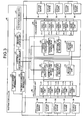
- FIG. 3 is a diagram exemplifying the configuration of the computer system.
- FIG. 4 is a diagram exemplifying information stored in a partition ID register.
- FIG. 5 is a diagram exemplifying the configuration of a system board.
- FIG. 6 is a diagram exemplifying a connection of components.
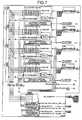
- FIG. 7 is a diagram exemplifying the configuration of a crossbar unit.
- the computer system 10 includes the plurality of crossbar units 20, the plurality of system boards 30, and the system controller 40.
- the crossbar unit 20 includes, in addition to a plurality of first control units 21 and the single (or a plurality of) second control unit(s) 22, particularly a partition ID register 23, an enable signal generation unit 24, and an error report unit 25.
- the first control unit 21 controls communication between the system board 30 connected to the crossbar unit 20 and the crossbar unit 20. In other words, the first control unit 21 performs priority control of communication between the crossbar unit 20 and each of the system boards 30.
- the second control unit 22 is connected to the first control units 21 to control communication with the other crossbar units 20. In other words, the second control unit 22 performs priority control of communication between the crossbar units 20.
- the partition ID register 23 stores information copying IDs of partitions stored in a partition ID register 41 described later.
- the partition ID register 23 may also be called a "copying information storage unit" as described in claims.
- the enable signal generation unit 24 generates an enable signal to determine whether each of the system boards 30 connected to the crossbar unit 20 is under the control of the failed control unit by using IDs of partitions stored in the partition ID register 23.
- the error report unit 25 sends, when a control unit fails, an error signal of each of the system boards 30 under the control of the failed control unit to the system controller 40.
- the error report unit 25 receives an error signal that is sent from a failed control unit and identifies the control unit.
- the error report unit 25 determines, among the system boards 30 connected to the crossbar unit 20, the system boards 30 under the control of the failed control unit based on the received error signal and an enable signal generated by the enable signal generation unit 24.
- the error report unit 25 sends an error signal of the determined system boards 30 to the system controller 40.
- the error report unit 25 may also be called a "processing apparatus information sending unit" as described in claims.
- the error report unit 25 further sends the error signal to the system controller 40.
- the error report unit 25 sends an error signal of the system boards 30 configured to be able to identify the second control unit 22 that has sent the error signal to the system controller 40.
- the system controller 40 includes the partition ID register 41, a partition determination unit 42, a stop command sending unit 43, a register update unit 44, and a re-drive command sending unit 45.
- the partition ID register 41 stores IDs of partitions uniquely attached to the partition to which the system board 30 belongs by associating with each of the system boards 30.
- the partition ID register 41 stores the partition ID (PID) and valid information (VAL) whether to send a re-drive command by associating with each of the system boards 30.
- Valid information "0" means sending a re-drive command and valid information "1" means not sending a re-drive command.
- the partition ID register 41 may also be called a "partition information storage unit" as described in claims.
- the partition determination unit 42 determines to which of partitions that logically divide the system the system board 30 corresponding to the error signal of the system board 30 received from the crossbar unit 20 belongs.
- the partition determination unit 42 determines the system boards 30 associated with the partition having the same ID as the partition ID corresponding to an error signal of the system board 30 received from the crossbar unit 20 from the partition ID register 41.
- the partition ID register 41 may also be called a "stop command sending unit" as described in claims.
- the stop command sending unit 43 sends a stop command to each of the determined system boards 30.
- the stop command sending unit 43 may also be called a "stop command sending unit" as described in claims.
- the register update unit 44 registers sending disapproval information with the partition ID register 41 by associating with the system board 30 to which a re-drive command is not to be sent.
- the register update unit 44 registers sending disapproval information with the partition ID register 41 by associating with the error signal of the system board 30.
- the register update unit 44 causes the partition ID register 23 to update by generating copy information by copying IDs of partitions stored in the partition ID register 41.
- the re-drive command sending unit 45 determines whether sending disapproval information is registered with the partition ID register 41 by being associated with each of the system boards 30 acquired by the stop command sending unit 43.
- the re-drive command sending unit 45 sends a re-drive command to the system boards 30 corresponding to the system boards 30 for which a determination result that sending disapproval information is not stored by being associated therewith is obtained.
- the system board 30 is a device as illustrated in FIG. 5 .
- An “SC (system bus controller)” performs bus control between the CPU, SC, MAC, and the crossbar unit 20.
- a “MAC (memory access controller)” performs bus control between memories (for example, DIMM).
- a “MBC (maintenance bus controller)” includes interfaces with all chips included in the system board 30 and also performs bus control between the system board 30 and the system controller 40.
- the crossbar unit 20 and the system board 30 perform communication with the system controller 40.
- Each MBC is connected through a serial interface called a maintenance bus and the function thereof is realized by firmware.
- information stored in the partition ID register 23 is information set as JTAG (Joint Test Action Group) by firmware via the MBC.
- the crossbar unit 20 is a device as illustrated in FIG. 7.
- (A) in FIG. 7 is an error signal sent from each control unit to the error report unit 25 (not illustrated in FIG. 7 ).
- (B) in FIG. 7 and (C) in FIG. 7 are signals used by the second control unit 22 for priority control.
- (D) in FIG. 7 is a signal used by the first control unit 21 for priority control.
- FIG. 8 is a flow chart illustrating the flow of processing by a crossbar unit.
- FIG. 9 is a flow chart illustrating the flow of processing by a system controller.
- the crossbar unit 20 detects that a control unit has failed (step S1001, Yes), the crossbar unit 20 outputs an error signal from the failed control unit (step S1002).
- the crossbar unit 20 determines the system boards 30 under the control of the failed control unit and sends an error signal of the determined system boards 30 to the system controller 40 (step S1003).
- the crossbar unit 20 stops driving of the system boards 30 according to a stop command received from the system controller 40 (step S1004).
- the crossbar unit 20 receives copy information from the system controller 40 to update information registered with the partition ID register 23 (step S1005).
- the crossbar unit 20 restarts driving of the system boards 30 according to a re-drive command received from the system controller 40 (step S1006) before completing the processing.
- the system controller 40 determines the partition to which the system board 30 corresponding to the received system board 30 belongs (step S2002).
- the system controller 40 sends a stop command to stop each of the system boards 30 belonging to the determined partition (step S2003) and registers sending disapproval information with the partition ID register 41 to update the partition ID register 23 (step S2004).
- the system controller 40 sends a re-drive command to the system boards 30 for which a determination result that sending disapproval information is not stored by being associated therewith is obtained (step S2005) before completing the processing.
- stuck-at control can be performed without causing the availability ratio of a computer system to fall.
- stuck-at control can be performed without causing the availability ratio of a computer system to fall because the computer system 10 performs stuck-at control without stopping driving of each of the system boards 30 that is not subject to the control of a failed control unit.
- the partitions to which the system boards 30 under the control of a failed control unit belong can be determined based on correspondence information between the system board 30 and partition ID and therefore, stuck-at control can be performed without causing the availability ratio of a computer system to fall.
- the system boards 30 under the control of a failed control unit can be determined based on an enable signal and error signal and therefore, stuck-at control can be performed without causing the availability ratio of a computer system to fall.
- each system board excluding the system board corresponding to the failed control unit can be restarted and therefore, stuck-at control can be performed without causing the availability ratio of a computer system to fall.
- the computer system 10 will be described in more detail by taking concrete examples.
- the first embodiment will be described in the order of the configuration of a computer system according to the first embodiment and effects of the first embodiment.
- FIGS. 10 to 17 Details of the configuration of the computer system 10 described above will be described below.
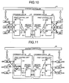
- FIG. 10 is a diagram illustrating the physical connection of a computer system according to the first embodiment.
- FIG. 11 is a diagram illustrating partitions built in the computer system according to the first embodiment.
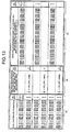
- FIG. 12 is a diagram exemplifying information stored in a partition ID register according to the first embodiment.
- FIGS. 13 and 14 are diagrams illustrating processing by an enable signal generation unit according to the first embodiment.
- FIG. 15 is a diagram exemplifying a circuit configuration of the enable signal generation unit according to the first embodiment.
- FIGS. 16 and 17 are diagrams exemplifying the circuit configuration of an error report unit according to the first embodiment.
- each component of the computer system 10 according to the first embodiment has a physical connection illustrated in FIG. 10 . It is also assumed that partitions illustrated in FIG. 11 are built in the computer system 10 according to the first embodiment.
- the first control unit 21 includes failure checkers that detect failures that occur in the first control unit 21 such as a bus parity checker and priority conflict checker.
- the failure checkers of the first control unit 21 typically send an error signal containing applicability information indicating whether the error signal is valid and the ID of the first control unit 21 to the error report unit 25.
- '1' indicates that the error signal is valid and '0' indicates that the error signal is invalid.
- the second control unit 22 includes failure checkers that detect failures that occur in the second control unit 22 such as a bus checker.
- the failure checkers of the second control unit 22 typically send an error signal containing applicability information indicating whether the error signal is valid and the ID of the second control unit 22 to the error report unit 25. For example, a failure checker of the second control unit 22 "#1" sends an error signal "control unit 2#1_ERR '1'".
- the partition ID register 23 and the partition ID register 41 store the partition ID (PID) and valid information (VAL) whether to send a re-drive command by associating with the ID of the system board 30 for each of the crossbar units 20.
- the partition ID register 23 and the partition ID register 41 may store the ID of the crossbar unit 20 to which the system board 30 is connected by associating with the error signal of the system board 30.
- the enable signal generation unit 24 typically sends an enable signal generated by using matching logic illustrated in FIG. 13 or 14 to the error report unit 25.
- the enable signal generation unit 24 also includes a circuit as illustrated in FIG. 15 .
- FIGS. 13 and 15 correspond to the enable signal generation unit 24 included in the crossbar unit 20 "#0" (hereinafter, denoted as the enable signal generation unit 24 "#0") and FIG. 14 corresponds to the enable signal generation unit 24 included in the crossbar unit 20 "#1".
- a circuit obtained by replacing "SB0" by “SB3", “SB1” by “SB4", “SB2” by “SB5", “SB3” by “SB0", “SB4" by “SB1", and “SB5" by “SB3" in the circuit illustrated in FIG. 15 corresponds to the enable signal generation unit 24 "#1".
- the enable signal generation unit 24 "#0" determines whether partition information is the same by checking the ID of the partition to which the system board 30 belongs against IDs of partitions of all the system boards 30 mounted on the computer system 10 (see (A) in FIG. 13 and (A) in FIG. 15 ).
- (A-1) in FIG. 13 means that a determination result "1" indicating that the partition "#1" of the system board 30 "SB0" and the partition "#1" of the system board 30 "SB0" are the same is obtained.
- (A-2) in FIG. 13 means that a determination result "0" indicating that the partition "#0" of the system board 30 "SB0" and the partition "#2" of the system board 30 "SB2" are not the same is obtained.
- the enable signal generation unit 24 "#0" generates an enable signal to determine whether each of the system boards 30 connected to the crossbar unit 20 "#0" is under the control of the second control unit 22 included in the crossbar unit 20 "#0" (see (B) in FIG. 13 and (B) in FIG. 15 ).
- (B-1) in FIG. 13 means that an enable signal "XB1_ERR_ENB[0] '0'” indicating that the system board 30 "SB0" is not under the control of the second control unit 22 "#1" included in the crossbar unit 20 "#0" is generated.
- (B-2) in FIG. 13 means that an enable signal "XB1_ERR_ENB[2] '1'" indicating that the system board 30 "SB2" is under the control of the second control unit 22 included in the crossbar unit 20 "#0" is generated.
- the enable signal generation unit 24 "#0" generates an enable signal to determine whether each of the system boards 30 connected to the crossbar unit 20 "#0" is under the control of the first control unit 21 included in the crossbar unit 20 "#0” based on the determination result and each generated enable signal (see (C) in FIG. 13 and (C) in FIG. 15 ).
- (C-1) in FIG. 13 means that an enable signal "SB0_ERR_ENB[0] '1'" indicating that the system board 30 "SB0" is under the control of the first control unit 21 "#0" included in the crossbar unit 20 "#0" is generated.
- (C-2) in FIG. 13 means that an enable signal "SB0_ERR_ENB[2] '0'” indicating that the system board 30 "SB0" is not under the control of the first control unit 21 "#2" included in the crossbar unit 20 "#0" is generated.
- the error report unit 25 includes a circuit as illustrated in FIGS. 16 and 17 .
- the error report unit 25 typically sends the ID of the system board 30 containing applicability information indicating whether the ID of the system board 30 is valid to the system controller 40.
- the error report unit 25 typically sends an error signal received from the failure checker of the first control unit 21 to the register update unit 44. Also, the error report unit 25 typically sends the ID of the second control unit 22 and the ID of the system board 30 containing applicability information indicating whether the ID of the system board 30 is valid to the system controller 40.
- the error report unit 25 "#0" sends an error signal "control unit 1#0_ERR '1'" received from the failure checker of the first control unit 21 "#1" to the system controller 40.
- the error report unit 25 "#0" checks an enable signal "SBO_ERR_ENB[0] '1'” generated by the enable signal generation unit 24 "#0” against the error signal "control unit 1#0_ERR '1'” (see (A) in FIG. 16 ).
- the error report unit 25 "#0" determines whether there is any signal containing applicability information "'1'” indicating being valid among signals obtained by checking (for example, "control unit 1#0_ERR[0] '1'").
- the error report unit 25 "#0" typically sends the ID ("PRTITION_ERR_SB0 '1'") of the system board 30 "SB0" containing applicability information indicating being valid to the system controller 40 (see (A) in FIG. 17 ).
- the error report unit 25 "#0" checks an enable signal "XB1_ERR_ENB [2] '1'” generated by the enable signal generation unit 24 "#0" against the an error signal "control unit 2#1_ERR '1'” (see (B) in FIG. 16 ).
- the error report unit 25 '#0" sends each signal (for example, "control unit 2#1_ERR[0] '1'") obtained by checking to the system controller 40.
- the error report unit 25 "#0" determines whether there is any signal containing applicability information "'1'” indicating being valid among signals obtained by checking (for example, "control unit 2#1_ERR[2] '1'” ).
- the error report unit 25 "#0" typically sends the ID ("PRTITION_ERR_SB2 '0'") of the system board 30 "SB2" containing applicability information indicating being valid to the system controller 40 (see (B) in FIG. 17 ).
- the partition determination unit 42 recognizes a system board 30 "SB0" error contained in the error report.
- the partition determination unit 42 acquires the ID of the partition "ID#1" corresponding to the system board 30 "SB0" from the partition ID register 41.
- the partition determination unit 42 determines the partition "ID#1" as the partition to which the system board 30 "SB0" belongs.
- the stop command sending unit 43 acquires the system board 30 "SB0" and the system board 30 "SB1" corresponding to the ID of the partition "ID#1" from the partition ID register 41.
- the stop command sending unit 43 sends a stop command to each of the system board 30 "SB0" and the system board 30 "SB1".
- the register update unit 44 registers valid information "1" with the partition ID register 41 by associating with the ID of the system board 30 "SB0" corresponding to the first control unit 21 "#1" included in the crossbar unit 20 "#1".
- control unit 2#1_ERR[0] '1'" is received from the error report unit 25 "#1"
- the register update unit 44 extracts the system board 30 "SB0" contained in the signal and registers valid information "1" with the partition ID register 41 by associating with the system board 30 "SB0".
- the re-drive command sending unit 45 determines whether valid information "1" is registered by associating with the system board 30 "SB0" and the system board 30 "SB1".
- the re-drive command sending unit 45 If the re-drive command sending unit 45 obtains a determination result that valid information "0" is not stored by associating with the system board 30 "SB0", the re-drive command sending unit 45 sends a re-drive command to the system board 30 "SB0".
- stuck-at control can be performed without causing the availability ratio of the computer system 10 to fall.
- the computer system 10 will be described by taking another concrete example.
- the second embodiment will be described in the order of the configuration of a computer system according to the second embodiment and effects of the second embodiment.
- FIGS. 18 to 28 the configuration of a computer system according to the second embodiment will be described using FIGS. 18 to 28 . Differences from the configuration of the computer system 10 according to the first embodiment will be described below.
- FIG. 18 is a diagram illustrating the physical connection of a computer system according to the second embodiment.
- FIG. 19 is a diagram illustrating partitions built in the computer system according to the second embodiment.
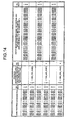
- FIG. 20 is a diagram exemplifying information stored in the partition ID register according to the second embodiment.
- FIGS. 21 to 25 are diagrams illustrating processing by the enable signal generation unit according to the second embodiment.
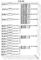
- FIG. 26 is a diagram exemplifying the circuit configuration of the enable signal generation unit according to the second embodiment.
- FIGS. 27 and 28 are diagrams exemplifying the circuit configuration of the error report unit according to the second embodiment.
- each component of the computer system 10 according to the second embodiment has a physical connection illustrated in FIG. 18 . It is also assumed that partitions illustrated in FIG. 19 are built in the computer system 10 according to the second embodiment.
- the partition ID register 23 and the partition ID register 41 store the ID of the system board 30, partition ID (PID), and valid information (VAL) as illustrated in FIG. 20 .
- the enable signal generation unit 24 typically sends an enable signal generated by using matching logic illustrated in FIGS. 21 to 25 to the error report unit 25.
- the enable signal generation unit 24 also includes a circuit as illustrated in FIG. 26 .
- FIGS. 21 , 22 , and 26 correspond to the enable signal generation unit 24 "#0", FIG. 23 to the enable signal generation unit 24 "#1", FIG. 24 to the enable signal generation unit 24 "#2", and FIG. 25 to the enable signal generation unit 24 "#4".
- Matching logic or circuits illustrated in FIGS. 22 to 26 are partially omitted for convenience of description.
- the error report unit 25 includes a circuit a illustrated in FIGS. 27 and 28 .
- FIGS. 27 and 28 assume that the second control unit 22 "#3" included in the crossbar unit 20 "#0" has failed (see “Failure 2" in FIG. 19 ).
- stuck-at control can be performed without causing the availability ratio of the computer system 10 to fall.
- the computer system 10 may stop driving of control units related to a failed control unit.
- the computer system 10 may stop driving of the first control unit 21 "#0" and the first control unit 21 "#1" included in the crossbar unit 20 "#0".
- the computer system 10 may stop driving of the first control unit 21 "#2", the first control unit 21 “#3", and the second control unit 22 "#3" included in the crossbar unit 20 "#0" and the first control unit 21 "#1", the first control unit 21 "#2", and the first control unit 21 "#3" included in the crossbar unit 20 "#3".
- Information for example, storage information illustrated in FIGS. 4 , 12 , and 20 ) including processing procedures, control procedures, concrete names, and various kinds of data and parameters illustrated in the above document and drawings may be changed optionally if not specifically mentioned.
- each component of each illustrated device is functionally conceptual and need not necessarily be configured physically as illustrated. That is, concrete forms of distribution/integration of each device is not limited to the illustrated forms and all or a portion thereof may be reconfigured by functional or physical distribution/integration in any unit according to various loads or usage.
- the partition determination unit 42 and the stop command sending unit 43 illustrated in FIG. 3 may be configured by integration thereof.
- each processing function executed by each device can be realized by a CPU and a program parsed and executed by the CPU.
- the present embodiment may be realized by executing a prepared program by the computer system 10.
- a computer that executes an error handling program having the function similar to that of the computer system 10 illustrated in the above embodiments is taken as an example for the description below by using FIG. 29.
- FIG. 29 is a diagram illustrating a computer executing an error handling program.
- the computer system 10 particularly includes a ROM 50
- the crossbar unit 20 particularly includes a CPU 26 and a RAM 27, and the system controller 40 particularly includes a CPU 46 and a RAM 47.
- the ROM 50 stores in advance a data processing program that carries out the same function as that of the computer system 10 illustrated in the first embodiment, that is, as illustrated in FIG. 29 , an error report program 50a, an enable signal generation program 50b, a stop command sending program 50c, a re-drive command sending program 50d, a partition determination program 50e, and a register update program 50f.
- these programs 130a to 130f may be integrated or distributed when necessary.
- the CPU 26 reads the error report program 50a and the enable signal generation program 50b from the ROM 50 for execution and the CPU 46 reads the stop command sending program 50c, the re-drive command sending program 50d, the partition determination program 50e, and the register update program 50f from the ROM 50 for execution.
- the computer system 10 causes the programs 50a to 50f to function as an error report program process 26a, an enable signal generation process 26b, a stop command sending program 26c, a re-drive command sending program 26d, a partition determination program 26e, and a register update program 26f.
- the processes 26a to 26f correspond to the enable signal generation unit 24, the error report unit 25, the partition determination unit 42, the stop command sending unit 43, the register update unit 44, the re-drive command sending unit 45 illustrated in FIG. 3 , respectively.
- the CPU 26 performs processing based on partition ID data 27a stored in the RAM 27 and the CPU 46 performs processing based on partition ID data 47a stored in the RAM 47.
- the partition ID data 27a corresponds to the partition ID register 23 illustrated in FIG. 3 and the partition ID data 47a corresponds to the partition ID register 41 illustrated in FIG. 3 .
- Each of the above programs 50a to 50f need not necessarily be caused to store in the ROM 50 from the beginning and, for example, may be caused to store in a "portable physical medium” inserted into the computer system 10 such as a flexible disk (FD), CD-ROM, DVD disk, magneto-optical disk, and IC card, a "fixed physical medium” provided inside or outside the computer system 10 such as an HDD, and further "another computer (or server)" connected to the computer system 10 via a public network, the Internet, LAN, and WAN so that the computer system 10 can read each program therefrom to execute the program.
- a "portable physical medium” inserted into the computer system 10 such as a flexible disk (FD), CD-ROM, DVD disk, magneto-optical disk, and IC card
- a "fixed physical medium” provided inside or outside the computer system 10 such as an HDD
- another computer or server
- the data processing method described in the present embodiment may also be realizable by executing a program prepared in advance on a computer such as a personal computer and workstation.
- the program can be distributed via a network such as the Internet.
- the program may also be recorded in a computer readable recording medium such as a hard disk, flexible disk (FD), CD-ROM, MO, and DVD so that the program is read from the recording medium by the computer for execution.
- a computer readable recording medium such as a hard disk, flexible disk (FD), CD-ROM, MO, and DVD
Landscapes
- Engineering & Computer Science (AREA)
- Theoretical Computer Science (AREA)
- Physics & Mathematics (AREA)
- Quality & Reliability (AREA)
- General Engineering & Computer Science (AREA)
- General Physics & Mathematics (AREA)
- Mathematical Physics (AREA)
- Hardware Redundancy (AREA)
- Multi Processors (AREA)
Abstract
Description
- The present invention relates to a data processing system, a data processing method, and a data processing program.
- A computer system in which combinations of predetermined system boards (SB) among a plurality of system boards mounted on the computer system are managed as partitions that logically divide the system and data processing is performed for respective system boards belonging to each partition has been known (see Patent Document 1).
- The configuration of such a computer system will be described more concretely. The computer system includes a plurality of data transfer circuits called crossbar units (KB) and a plurality of system boards is connected to each crossbar unit.
- The computer system includes a system controller (corresponding to, for example, SCF (System Control Facility) or MMB (Management Board)) that controls communication between system boards belonging to the same partition by managing each first control unit and each second control unit included in each crossbar unit.
- The first control unit of these control units each corresponds to each system board connected to the crossbar unit and performs priority control of communication between system boards by controlling communication between each system board under control among system boards connected to the crossbar unit and the crossbar unit.
- The second control unit each corresponds to a different crossbar unit from the crossbar unit including the second control unit and performs priority control of communication between system boards by controlling communication between the crossbar unit including the second control unit and each of different crossbar units.
- If a control unit (a first control unit or second control unit) included in a crossbar unit fails in such a computer system, stuck-at control to cause the system board corresponding to the failed control unit to be stuck (separate) from under the control of the failed control unit is performed.
- A concrete example of the stuck-at control will be described. If a first control unit fails, the crossbar unit sends an error signal to the system controller.
- The system controller that has received the error signal sends a stop command to temporarily stop driving of all system boards. Subsequently, the system controller sends a re-drive command to re-drive each system board excluding the system board corresponding to the failed first control unit.
- In this manner, the computer system causes the system board corresponding to the failed control unit to be stuck from under the control of the failed control unit.
- Patent Document 1: Japanese Laid-open Patent Publication No.
2006-31199 - The above conventional technique has a problem that the availability ratio of a computer system falls when stuck-at control is performed. That is, a conventional computer system has a problem that the availability ratio of the computer system falls because driving of system boards that are not subject to the failed control unit, in other words, driving of system boards whose driving need not be stopped is also stopped when stuck-at control is performed.
- Thus, a data processing system, a data processing method, and a data processing program have been devised to solve the above problem of the conventional technique and an object thereof is to provide a data processing system, a data processing method, and a data processing program capable of performing stuck-at control without causing the availability ratio of a computer system to fall.
- To solve the above problem and achieve the object, a data processing system disclosed herein includes a data transfer apparatus that include control units to control communication between the data processing apparatuses and include a processing apparatus information sending unit that sends, when the control unit fails, a piece of processing apparatus information corresponding to the data processing apparatus under control of the failed control unit from among pieces of processing apparatus information uniquely attached respectively to the data processing apparatuses to a system control apparatus; and the system control apparatus that includes a stop command sending unit that determines to which of partitions that logically divide the system the data processing apparatus corresponding to the piece of processing apparatus information received from the data transfer apparatus belongs, the stop command sending unit sending a stop command to stop driving of the data processing apparatus belonging to the determined partition.
- According to a disclosed data processing system, data processing method, and data processing program, stuck-at control can be performed without causing the availability ratio of a computer system to fall.
-
-
FIG. 1 is a diagram illustrating a physical connection of a computer system. -
FIG. 2 is a diagram illustrating partitions built in the computer system. -
FIG. 3 is a diagram exemplifying the configuration of the computer system. -
FIG. 4 is a diagram exemplifying information stored in a partition ID register. -
FIG. 5 is a diagram exemplifying the configuration of a system board. -
FIG. 6 is a diagram exemplifying a connection of components. -
FIG. 7 is a diagram exemplifying the configuration of a crossbar unit. -
FIG. 8 is a flow chart illustrating the flow of processing by the crossbar unit. -
FIG. 9 is a flow chart illustrating the flow of processing by a system controller. -
FIG. 10 is a diagram illustrating the physical connection of the computer system according to a first embodiment. -
FIG. 11 is a diagram illustrating partitions built in the computer system according to the first embodiment. -
FIG. 12 is a diagram exemplifying the information stored in the partition ID register according to the first embodiment. -
FIG. 13 is a diagram illustrating processing by an enable signal generation unit according to the first embodiment. -
FIG. 14 is a diagram illustrating the processing by the enable signal generation unit according to the first embodiment. -
FIG. 15 is a diagram exemplifying a circuit configuration of the enable signal generation unit according to the first embodiment. -
FIG. 16 is a diagram exemplifying the circuit configuration of an error report unit according to the first embodiment. -
FIG. 17 is a diagram exemplifying the circuit configuration of the error report unit according to the first embodiment. -
FIG. 18 is a diagram illustrating the physical connection of the computer system according to a second embodiment. -
FIG. 19 is a diagram illustrating partitions built in the computer system according to the second embodiment. -
FIG. 20 is a diagram exemplifying the information stored in the partition ID register according to the second embodiment. -
FIG. 21 is a diagram illustrating the processing by the enable signal generation unit according to the second embodiment. -
FIG. 22 is a diagram illustrating the processing by the enable signal generation unit according to the second embodiment. -
FIG. 23 is a diagram illustrating the processing by the enable signal generation unit according to the second embodiment. -
FIG. 24 is a diagram illustrating the processing by the enable signal generation unit according to the second embodiment. -
FIG. 25 is a diagram illustrating the processing by the enable signal generation unit according to the second embodiment. -
FIG. 26 is a diagram exemplifying the circuit configuration of the enable signal generation unit according to the second embodiment. -
FIG. 27 is a diagram exemplifying the circuit configuration of the error report unit according to the second embodiment. -
FIG. 28 is a diagram exemplifying the circuit configuration of the error report unit according to the second embodiment. -
FIG. 29 is a diagram illustrating a computer executing a data processing program. -
- 10
- Computer system
- 20
- Crossbar unit
- 21
- First control unit
- 22
- Second control unit
- 23
- Partition ID register
- 24
- Enable signal generation unit
- 25
- Error report unit
- 26
- CPU (Central Processing Unit)
- 26a
- Enable signal generation process
- 26b
- Error report process
- 27
- RAM (Random Access Memory)
- 27a
- Partition ID data
- 30
- System board
- 40
- System controller
- 41
- Partition ID register
- 42
- Partition determination unit
- 43
- Stop command sending unit
- 44
- Register update unit
- 45
- Re-drive command sending unit
- 46
- CPU (Central Processing Unit)
- 46a
- Partition determination process
- 46b
- Stop command sending process
- 46c
- Register update process
- 46d
- Re-drive command sending process
- 47
- RAM (Random Access Memory)
- 47a
- Partition ID data
- Embodiments of a data processing system, a data processing method, and a data processing program according to an example of the present embodiments will be described in detail below with reference to accompanying drawings. The embodiment of a computer system to which the present embodiment is applied will be described in the order of an overview of the computer system, the configuration of the computer system, and processing by the computer system and lastly, effects of the computer system will be described.
- First, an overview of a
computer system 10 will be provided usingFIGS. 1 and 2. FIG. 1 is a diagram illustrating a physical connection of a computer system.FIG. 2 is a diagram illustrating partitions built in the computer system. - As illustrated in
FIG. 1 , thecomputer system 10 includes a plurality of crossbar units (XB) 20, a plurality of system boards (SB) 30, and asystem controller 40. Each component of thecomputer system 10 has a physical connection illustrated inFIG. 1 . - An ID (for example, "SB0" and "SB1") to identify the
system board 30 is attached to each of thesystem boards 30. Hereinafter, thesystem board 30 corresponding to "SB0" will be denoted as asystem board 30 "SB0". - Also, an ID (for example, "#0" and "#1") to identify each component is attached to the
crossbar unit 20, afirst control unit 21, and asecond control unit 22. Hereinafter, for example, thefirst control unit 21 corresponding to "#0" will be denoted as thefirst control unit 21 "#0". - When a control unit (the
first control unit 21 or the second control unit 22) fails, thecrossbar unit 20 of thecomputer system 10 sends an error signal corresponding to, among thesystem boards 30, thesystem board 30 under the control of the failed control unit to thesystem controller 40. - Subsequently, the
system controller 40 determines to which of partitions that logically divide the system thesystem board 30 corresponding to each error signal belongs and sends a stop command to stop driving of each of thesystem boards 30 belonging to the determined partition. - Degradation control by the
computer system 10 will be described below by taking concrete examples. A partition ID (for example, "#1" and "#2") attached uniquely is attached to each partition to which thesystem board 30 belongs. Hereinafter, the partition corresponding to "ID# 1" will be denoted as the partition "ID# 1". - First, a case when the
first control unit 21 "#1" included in thecrossbar unit 20 "#0" fails will be described as Failure 1 (seeFailure 1 inFIG. 2 ). - In the case of
Failure 1, thecrossbar unit 20 "#0" sends an error signal of thesystem board 30 "SB0" and asystem board 30 "SB1" under the control of thefirst control unit 21 "#1" included in thecrossbar unit 20 "#0" to thesystem controller 40. - The
system controller 40 that has received the error signal of thesystem board 30 "SB0" and thesystem board 30 "SB1" determines that thesystem board 30 "SB0" and thesystem board 30 "SB1" belong to the partition "ID# 1". - Subsequently, the
system controller 40 sends a stop command to stop driving of thesystem board 30 "SB0" and thesystem board 30 "SB1" belonging to the partition "ID# 1". - Then, the
system controller 40 sends a re-drive command to re-drive thesystem board 30 "SB0" before completing the stuck-at control. - Next, a case when the
first control unit 21 "#4" included in thecrossbar unit 20 "#0" fails will be described as Failure 2 (seeFailure 2 inFIG. 2 ). - In the case of
Failure 2, thecrossbar unit 20 "#0" notifies thesystem controller 40 of an error signal of asystem board 30 "SB2", asystem board 30 "SB3", and asystem board 30 "SB4" under the control of thefirst control unit 21 "#4" included in thecrossbar unit 20 "#0". - The
system controller 40 that has received the error signal of thesystem board 30 "SB2", thesystem board 30 "SB3", and thesystem board 30 "SB4" determines that thesystem board 30 "SB2" and thesystem board 30 "SB3" belong to a partition "ID# 2". - The
system controller 40 also determines that thesystem board 30 "SB4" belongs to a partition "ID# 3". - Subsequently, the
system controller 40 sends a stop command to stop driving of thesystem board 30 "SB2", thesystem board 30 "SB3", and asystem board 30 "SBn" belonging to the partition "ID# 2". - The
system controller 40 also sends a stop command to stop driving of thesystem board 30 "SB4", asystem board 30 "SBn+1", and asystem board 30 "SBn+2" belonging to the partition "ID# 3". - Then, the
system controller 40 sends a re-drive command to re-drive thesystem board 30 "SB2", thesystem board 30 "SB3", thesystem board 30 "SBn", thesystem board 30 "SBn+1", and thesystem board 30 "SBn+2" before completing the stuck-at control. - Next, a case when the
second control unit 22 "#m" included in acrossbar unit 20 "#m" fails will be described as Failure 3 (seeFailure 3 inFIG. 2 ). - In the case of
Failure 3, thecrossbar unit 20 "#m" notifies thesystem controller 40 of an error signal of thesystem board 30 "SBn", thesystem board 30 "SBn+1", and thesystem board 30 "SBn+2" under the control of thesecond control unit 22 "#m" included in thecrossbar unit 20 "#m". - The
system controller 40 that has received the error signal of thesystem board 30 "SBn", thesystem board 30 "SBn+1", and thesystem board 30 "SBn+2" determines that thesystem board 30 "SBn" belongs to the partition "ID# 2". - The
system controller 40 also determines that thesystem board 30 "SBn+1" and thesystem board 30 "SBn+2" belong to the partition "ID# 3". - Subsequently, the
system controller 40 sends a stop command to stop driving of thesystem board 30 "SB2", thesystem board 30 "SB3", and thesystem board 30 "SBn" belonging to the partition "ID# 2". - The
system controller 40 also sends a stop command to stop driving of thesystem board 30 "SB4", asystem board 30 "SBn+1", and asystem board 30 "SBn+2" belonging to the partition "ID# 3". - Then, the
system controller 40 sends a re-drive command to re-drive thesystem board 30 "SB2", thesystem board 30 "SB3", and thesystem board 30 "SB4" before completing the stuck-at control. - Next, the function configuration of the
computer system 10 will be described usingFIGS. 3 to 7 .FIG. 3 is a diagram exemplifying the configuration of the computer system.FIG. 4 is a diagram exemplifying information stored in a partition ID register.FIG. 5 is a diagram exemplifying the configuration of a system board.FIG. 6 is a diagram exemplifying a connection of components.FIG. 7 is a diagram exemplifying the configuration of a crossbar unit. - As illustrated in
FIG. 3 , thecomputer system 10 includes the plurality ofcrossbar units 20, the plurality ofsystem boards 30, and thesystem controller 40. - The
crossbar unit 20 includes, in addition to a plurality offirst control units 21 and the single (or a plurality of) second control unit(s) 22, particularly apartition ID register 23, an enablesignal generation unit 24, and anerror report unit 25. - The
first control unit 21 controls communication between thesystem board 30 connected to thecrossbar unit 20 and thecrossbar unit 20. In other words, thefirst control unit 21 performs priority control of communication between thecrossbar unit 20 and each of thesystem boards 30. - The
second control unit 22 is connected to thefirst control units 21 to control communication with theother crossbar units 20. In other words, thesecond control unit 22 performs priority control of communication between thecrossbar units 20. - The
partition ID register 23 stores information copying IDs of partitions stored in apartition ID register 41 described later. Thepartition ID register 23 may also be called a "copying information storage unit" as described in claims. - The enable
signal generation unit 24 generates an enable signal to determine whether each of thesystem boards 30 connected to thecrossbar unit 20 is under the control of the failed control unit by using IDs of partitions stored in thepartition ID register 23. - The
error report unit 25 sends, when a control unit fails, an error signal of each of thesystem boards 30 under the control of the failed control unit to thesystem controller 40. - More specifically, the
error report unit 25 receives an error signal that is sent from a failed control unit and identifies the control unit. - Subsequently, the
error report unit 25 determines, among thesystem boards 30 connected to thecrossbar unit 20, thesystem boards 30 under the control of the failed control unit based on the received error signal and an enable signal generated by the enablesignal generation unit 24. - Then, the
error report unit 25 sends an error signal of thedetermined system boards 30 to thesystem controller 40. Theerror report unit 25 may also be called a "processing apparatus information sending unit" as described in claims. - If an error signal sent from the
first control unit 21 is received, theerror report unit 25 further sends the error signal to thesystem controller 40. - If an error signal sent from the
second control unit 22 is received, theerror report unit 25 sends an error signal of thesystem boards 30 configured to be able to identify thesecond control unit 22 that has sent the error signal to thesystem controller 40. - Particularly, the
system controller 40 includes thepartition ID register 41, apartition determination unit 42, a stopcommand sending unit 43, a register update unit 44, and a re-drivecommand sending unit 45. - The
partition ID register 41 stores IDs of partitions uniquely attached to the partition to which thesystem board 30 belongs by associating with each of thesystem boards 30. - More specifically, as illustrated in
FIG. 4 , thepartition ID register 41 stores the partition ID (PID) and valid information (VAL) whether to send a re-drive command by associating with each of thesystem boards 30. - Valid information "0" means sending a re-drive command and valid information "1" means not sending a re-drive command. The
partition ID register 41 may also be called a "partition information storage unit" as described in claims. - The
partition determination unit 42 determines to which of partitions that logically divide the system thesystem board 30 corresponding to the error signal of thesystem board 30 received from thecrossbar unit 20 belongs. - More specifically, the
partition determination unit 42 determines thesystem boards 30 associated with the partition having the same ID as the partition ID corresponding to an error signal of thesystem board 30 received from thecrossbar unit 20 from thepartition ID register 41. Thepartition ID register 41 may also be called a "stop command sending unit" as described in claims. - The stop
command sending unit 43 sends a stop command to each of thedetermined system boards 30. The stopcommand sending unit 43 may also be called a "stop command sending unit" as described in claims. - If an error signal sent from the
first control unit 21 is received, the register update unit 44 registers sending disapproval information with thepartition ID register 41 by associating with thesystem board 30 to which a re-drive command is not to be sent. - If an error signal of the
system board 30 of thesecond control unit 22 is received, the register update unit 44 registers sending disapproval information with thepartition ID register 41 by associating with the error signal of thesystem board 30. - Then, the register update unit 44 causes the
partition ID register 23 to update by generating copy information by copying IDs of partitions stored in thepartition ID register 41. - After sending disapproval information being registered by the register update unit 44, the re-drive
command sending unit 45 determines whether sending disapproval information is registered with thepartition ID register 41 by being associated with each of thesystem boards 30 acquired by the stopcommand sending unit 43. - The re-drive
command sending unit 45 sends a re-drive command to thesystem boards 30 corresponding to thesystem boards 30 for which a determination result that sending disapproval information is not stored by being associated therewith is obtained. - The
system board 30 is a device as illustrated inFIG. 5 . An "SC (system bus controller)" performs bus control between the CPU, SC, MAC, and thecrossbar unit 20. A "MAC (memory access controller)" performs bus control between memories (for example, DIMM). A "MBC (maintenance bus controller)" includes interfaces with all chips included in thesystem board 30 and also performs bus control between thesystem board 30 and thesystem controller 40. - Also in the
computer system 10, as illustrated inFIG. 6 , thecrossbar unit 20 and thesystem board 30 perform communication with thesystem controller 40. Each MBC is connected through a serial interface called a maintenance bus and the function thereof is realized by firmware. For example, information stored in thepartition ID register 23 is information set as JTAG (Joint Test Action Group) by firmware via the MBC. - The
crossbar unit 20 is a device as illustrated inFIG. 7. (A) inFIG. 7 is an error signal sent from each control unit to the error report unit 25 (not illustrated inFIG. 7 ). (B) inFIG. 7 and (C) inFIG. 7 are signals used by thesecond control unit 22 for priority control. (D) inFIG. 7 is a signal used by thefirst control unit 21 for priority control. - Next, processing by the
computer system 10 will be described usingFIGS. 8 and9 .FIG. 8 is a flow chart illustrating the flow of processing by a crossbar unit.FIG. 9 is a flow chart illustrating the flow of processing by a system controller. - When, as illustrated in
FIG. 8 , thecrossbar unit 20 detects that a control unit has failed (step S1001, Yes), thecrossbar unit 20 outputs an error signal from the failed control unit (step S1002). - Subsequently, the
crossbar unit 20 determines thesystem boards 30 under the control of the failed control unit and sends an error signal of thedetermined system boards 30 to the system controller 40 (step S1003). - Then, the
crossbar unit 20 stops driving of thesystem boards 30 according to a stop command received from the system controller 40 (step S1004). - Subsequently, the
crossbar unit 20 receives copy information from thesystem controller 40 to update information registered with the partition ID register 23 (step S1005). - Then, the
crossbar unit 20 restarts driving of thesystem boards 30 according to a re-drive command received from the system controller 40 (step S1006) before completing the processing. - When, as illustrated in
FIG. 9 , thesystem controller 40 receives an error signal of thesystem board 30 from the crossbar unit 20 (step S2001, Yes), thesystem controller 40 determines the partition to which thesystem board 30 corresponding to the receivedsystem board 30 belongs (step S2002). - Subsequently, the
system controller 40 sends a stop command to stop each of thesystem boards 30 belonging to the determined partition (step S2003) and registers sending disapproval information with thepartition ID register 41 to update the partition ID register 23 (step S2004). - Subsequently, the
system controller 40 sends a re-drive command to thesystem boards 30 for which a determination result that sending disapproval information is not stored by being associated therewith is obtained (step S2005) before completing the processing. - According to the
computer system 10, as described above, stuck-at control can be performed without causing the availability ratio of a computer system to fall. For example, stuck-at control can be performed without causing the availability ratio of a computer system to fall because thecomputer system 10 performs stuck-at control without stopping driving of each of thesystem boards 30 that is not subject to the control of a failed control unit. - Also according to the
computer system 10, the partitions to which thesystem boards 30 under the control of a failed control unit belong can be determined based on correspondence information between thesystem board 30 and partition ID and therefore, stuck-at control can be performed without causing the availability ratio of a computer system to fall. - Also according to the
computer system 10, thesystem boards 30 under the control of a failed control unit can be determined based on an enable signal and error signal and therefore, stuck-at control can be performed without causing the availability ratio of a computer system to fall. - Also according to the
computer system 10, driving of, among system boards under the control of a failed control unit, each system board excluding the system board corresponding to the failed control unit can be restarted and therefore, stuck-at control can be performed without causing the availability ratio of a computer system to fall. - In the first embodiment, the
computer system 10 will be described in more detail by taking concrete examples. The first embodiment will be described in the order of the configuration of a computer system according to the first embodiment and effects of the first embodiment. - First, the configuration of a computer system according to the first embodiment will be described using
FIGS. 10 to 17 . Details of the configuration of thecomputer system 10 described above will be described below. -
FIG. 10 is a diagram illustrating the physical connection of a computer system according to the first embodiment.FIG. 11 is a diagram illustrating partitions built in the computer system according to the first embodiment.FIG. 12 is a diagram exemplifying information stored in a partition ID register according to the first embodiment. -
FIGS. 13 and14 are diagrams illustrating processing by an enable signal generation unit according to the first embodiment.FIG. 15 is a diagram exemplifying a circuit configuration of the enable signal generation unit according to the first embodiment.FIGS. 16 and17 are diagrams exemplifying the circuit configuration of an error report unit according to the first embodiment. - It is assumed that each component of the
computer system 10 according to the first embodiment has a physical connection illustrated inFIG. 10 . It is also assumed that partitions illustrated inFIG. 11 are built in thecomputer system 10 according to the first embodiment. - The
first control unit 21 includes failure checkers that detect failures that occur in thefirst control unit 21 such as a bus parity checker and priority conflict checker. - The failure checkers of the
first control unit 21 typically send an error signal containing applicability information indicating whether the error signal is valid and the ID of thefirst control unit 21 to theerror report unit 25. A failure checker of thefirst control unit 21, for example, a failure checker of thefirst control unit 21 "#0" sends an error signal "control unit 1#0_ERR '1"'. - Here, '1' indicates that the error signal is valid and '0' indicates that the error signal is invalid.
- The
second control unit 22 includes failure checkers that detect failures that occur in thesecond control unit 22 such as a bus checker. - The failure checkers of the
second control unit 22 typically send an error signal containing applicability information indicating whether the error signal is valid and the ID of thesecond control unit 22 to theerror report unit 25. For example, a failure checker of thesecond control unit 22 "#1" sends an error signal "control unit 2#1_ERR '1'". - As illustrated in
FIG. 12 , thepartition ID register 23 and thepartition ID register 41 store the partition ID (PID) and valid information (VAL) whether to send a re-drive command by associating with the ID of thesystem board 30 for each of thecrossbar units 20. - The
partition ID register 23 and thepartition ID register 41 may store the ID of thecrossbar unit 20 to which thesystem board 30 is connected by associating with the error signal of thesystem board 30. - The enable
signal generation unit 24 typically sends an enable signal generated by using matching logic illustrated inFIG. 13 or14 to theerror report unit 25. The enablesignal generation unit 24 also includes a circuit as illustrated inFIG. 15 . -
FIGS. 13 and15 correspond to the enablesignal generation unit 24 included in thecrossbar unit 20 "#0" (hereinafter, denoted as the enablesignal generation unit 24 "#0") andFIG. 14 corresponds to the enablesignal generation unit 24 included in thecrossbar unit 20 "#1". - A circuit obtained by replacing "SB0" by "SB3", "SB1" by "SB4", "SB2" by "SB5", "SB3" by "SB0", "SB4" by "SB1", and "SB5" by "SB3" in the circuit illustrated in
FIG. 15 corresponds to the enablesignal generation unit 24 "#1". - A description will be provided by taking a concrete example. The enable
signal generation unit 24 "#0" determines whether partition information is the same by checking the ID of the partition to which thesystem board 30 belongs against IDs of partitions of all thesystem boards 30 mounted on the computer system 10 (see (A) inFIG. 13 and (A) inFIG. 15 ). - (A-1) in
FIG. 13 means that a determination result "1" indicating that the partition "#1" of thesystem board 30 "SB0" and the partition "#1" of thesystem board 30 "SB0" are the same is obtained. - (A-2) in
FIG. 13 means that a determination result "0" indicating that the partition "#0" of thesystem board 30 "SB0" and the partition "#2" of thesystem board 30 "SB2" are not the same is obtained. - Subsequently, based on the determination result, the enable
signal generation unit 24 "#0" generates an enable signal to determine whether each of thesystem boards 30 connected to thecrossbar unit 20 "#0" is under the control of thesecond control unit 22 included in thecrossbar unit 20 "#0" (see (B) inFIG. 13 and (B) inFIG. 15 ). - (B-1) in
FIG. 13 means that an enable signal "XB1_ERR_ENB[0] '0'" indicating that thesystem board 30 "SB0" is not under the control of thesecond control unit 22 "#1" included in thecrossbar unit 20 "#0" is generated. - (B-2) in
FIG. 13 means that an enable signal "XB1_ERR_ENB[2] '1'" indicating that thesystem board 30 "SB2" is under the control of thesecond control unit 22 included in thecrossbar unit 20 "#0" is generated. - Subsequently, the enable
signal generation unit 24 "#0" generates an enable signal to determine whether each of thesystem boards 30 connected to thecrossbar unit 20 "#0" is under the control of thefirst control unit 21 included in thecrossbar unit 20 "#0" based on the determination result and each generated enable signal (see (C) inFIG. 13 and (C) inFIG. 15 ). - (C-1) in
FIG. 13 means that an enable signal "SB0_ERR_ENB[0] '1'" indicating that thesystem board 30 "SB0" is under the control of thefirst control unit 21 "#0" included in thecrossbar unit 20 "#0" is generated. - (C-2) in
FIG. 13 means that an enable signal "SB0_ERR_ENB[2] '0'" indicating that thesystem board 30 "SB0" is not under the control of thefirst control unit 21 "#2" included in thecrossbar unit 20 "#0" is generated. - The
error report unit 25 includes a circuit as illustrated inFIGS. 16 and17 . Theerror report unit 25 typically sends the ID of thesystem board 30 containing applicability information indicating whether the ID of thesystem board 30 is valid to thesystem controller 40. - Also, the
error report unit 25 typically sends an error signal received from the failure checker of thefirst control unit 21 to the register update unit 44. Also, theerror report unit 25 typically sends the ID of thesecond control unit 22 and the ID of thesystem board 30 containing applicability information indicating whether the ID of thesystem board 30 is valid to thesystem controller 40. - In
FIGS. 16 and17 , it is assumed that thefirst control unit 21 "#1" included in thecrossbar unit 20 "#0" has failed (seeFailure 1 inFIG. 11 ). - A description will be provided by taking a concrete example. The
error report unit 25 "#0" sends an error signal "control unit 1#0_ERR '1'" received from the failure checker of thefirst control unit 21 "#1" to thesystem controller 40. - The
error report unit 25 "#0" checks an enable signal "SBO_ERR_ENB[0] '1'" generated by the enablesignal generation unit 24 "#0" against the error signal "control unit 1#0_ERR '1'" (see (A) inFIG. 16 ). - Then, the
error report unit 25 "#0" determines whether there is any signal containing applicability information "'1'" indicating being valid among signals obtained by checking (for example, "control unit 1#0_ERR[0] '1'"). - Since there is a signal containing applicability information "'11" indicating being valid, the
error report unit 25 "#0" typically sends the ID ("PRTITION_ERR_SB0 '1'") of thesystem board 30 "SB0" containing applicability information indicating being valid to the system controller 40 (see (A) inFIG. 17 ). - Also, the
error report unit 25 "#0" checks an enable signal "XB1_ERR_ENB [2] '1'" generated by the enablesignal generation unit 24 "#0" against the an error signal "control unit 2#1_ERR '1'" (see (B) inFIG. 16 ). - Then, the error report unit 25 '#0" sends each signal (for example, "
control unit 2#1_ERR[0] '1'") obtained by checking to thesystem controller 40. - Then, the
error report unit 25 "#0" determines whether there is any signal containing applicability information "'1'" indicating being valid among signals obtained by checking (for example, "control unit 2#1_ERR[2] '1'"). - Since there is no signal containing applicability information "'1'" indicating being valid, the
error report unit 25 "#0" typically sends the ID ("PRTITION_ERR_SB2 '0'") of thesystem board 30 "SB2" containing applicability information indicating being valid to the system controller 40 (see (B) inFIG. 17 ). - If, for example, the ID ("PRTITION_ERR_SBO '1'") of the
system board 30 "SB0" containing applicability information indicating being valid is received, thepartition determination unit 42 recognizes asystem board 30 "SB0" error contained in the error report. - Subsequently, the
partition determination unit 42 acquires the ID of the partition "ID# 1" corresponding to thesystem board 30 "SB0" from thepartition ID register 41. - Then, the
partition determination unit 42 determines the partition "ID# 1" as the partition to which thesystem board 30 "SB0" belongs. - If, for example, the partition "
ID# 1" is determined, the stopcommand sending unit 43 acquires thesystem board 30 "SB0" and thesystem board 30 "SB1" corresponding to the ID of the partition "ID# 1" from thepartition ID register 41. - Then, the stop
command sending unit 43 sends a stop command to each of thesystem board 30 "SB0" and thesystem board 30 "SB1". - If, for example, an error signal "
control unit 1#1_ERR '1'" is received from theerror report unit 25 "#1", the register update unit 44 registers valid information "1" with thepartition ID register 41 by associating with the ID of thesystem board 30 "SB0" corresponding to thefirst control unit 21 "#1" included in thecrossbar unit 20 "#1". - If, for example, "
control unit 2#1_ERR[0] '1'" is received from theerror report unit 25 "#1", the register update unit 44 extracts thesystem board 30 "SB0" contained in the signal and registers valid information "1" with thepartition ID register 41 by associating with thesystem board 30 "SB0". - If, for example, the ID of the partition "
ID# 1" is acquired by the stopcommand sending unit 43, the re-drivecommand sending unit 45 determines whether valid information "1" is registered by associating with thesystem board 30 "SB0" and thesystem board 30 "SB1". - If the re-drive
command sending unit 45 obtains a determination result that valid information "0" is not stored by associating with thesystem board 30 "SB0", the re-drivecommand sending unit 45 sends a re-drive command to thesystem board 30 "SB0". - According to the
computer system 10 of the first embodiment, as described above, if thefirst control unit 21 "#1" included in thecrossbar unit 20 "#0" fails, driving of thesystem board 30 "SB0" and thesystem board 30 "SB1" can be stopped. - Also according to the
computer system 10 of the first embodiment, driving of thesystem board 30 "SB0" can be restarted. - In this manner, according to the
computer system 10 of the first embodiment, stuck-at control can be performed without causing the availability ratio of thecomputer system 10 to fall. - In a second embodiment, the
computer system 10 will be described by taking another concrete example. The second embodiment will be described in the order of the configuration of a computer system according to the second embodiment and effects of the second embodiment. - First, the configuration of a computer system according to the second embodiment will be described using
FIGS. 18 to 28 . Differences from the configuration of thecomputer system 10 according to the first embodiment will be described below. -
FIG. 18 is a diagram illustrating the physical connection of a computer system according to the second embodiment.FIG. 19 is a diagram illustrating partitions built in the computer system according to the second embodiment.FIG. 20 is a diagram exemplifying information stored in the partition ID register according to the second embodiment. -
FIGS. 21 to 25 are diagrams illustrating processing by the enable signal generation unit according to the second embodiment.FIG. 26 is a diagram exemplifying the circuit configuration of the enable signal generation unit according to the second embodiment.FIGS. 27 and28 are diagrams exemplifying the circuit configuration of the error report unit according to the second embodiment. - It is assumed that each component of the
computer system 10 according to the second embodiment has a physical connection illustrated inFIG. 18 . It is also assumed that partitions illustrated inFIG. 19 are built in thecomputer system 10 according to the second embodiment. - The
partition ID register 23 and thepartition ID register 41 store the ID of thesystem board 30, partition ID (PID), and valid information (VAL) as illustrated inFIG. 20 . - The enable
signal generation unit 24 typically sends an enable signal generated by using matching logic illustrated inFIGS. 21 to 25 to theerror report unit 25. The enablesignal generation unit 24 also includes a circuit as illustrated inFIG. 26 . -
FIGS. 21 ,22 , and26 correspond to the enablesignal generation unit 24 "#0",FIG. 23 to the enablesignal generation unit 24 "#1",FIG. 24 to the enablesignal generation unit 24 "#2", andFIG. 25 to the enablesignal generation unit 24 "#4". Matching logic or circuits illustrated inFIGS. 22 to 26 are partially omitted for convenience of description. - "SBa" in
FIGS. 21 to 26 corresponds to "SB10", "SBb" to "SB11", "SBc" to "SB12", "SBd" to "SB13", "SBe" to "SB14", and "SBf" to "SB15". - The
error report unit 25 includes a circuit a illustrated inFIGS. 27 and28 .FIGS. 27 and28 assume that thesecond control unit 22 "#3" included in thecrossbar unit 20 "#0" has failed (see "Failure 2" inFIG. 19 ). - According to the
computer system 10 of the second embodiment, if thesecond control unit 22 "#3" included in thecrossbar unit 20 "#0" fails, driving of thesystem board 30 "SB2",system board 30 "SB3",system board 30 "SB13",system board 30 "SB14", andsystem board 30 "SB15" can be stopped. - Also according to the
computer system 10 of the first embodiment, driving of thesystem board 30 "SB13",system board 30 "SB14", andsystem board 30 "SB15" can be restarted. - In this manner, according to the
computer system 10 of the second embodiment, stuck-at control can be performed without causing the availability ratio of thecomputer system 10 to fall. - In addition to the above embodiments of the present data processing system, data processing method, and data processing program, various different embodiments may be carried out. Thus, another embodiment will be described as a third embodiment.
- For example, the
computer system 10 may stop driving of control units related to a failed control unit. - More specifically, if
Failure 1 occurs (seeFIG. 11 ), thecomputer system 10 according to the first embodiment may stop driving of thefirst control unit 21 "#0" and thefirst control unit 21 "#1" included in thecrossbar unit 20 "#0". - If
Failure 2 occurs (seeFIG. 19 ), thecomputer system 10 according to the first embodiment may stop driving of thefirst control unit 21 "#2", thefirst control unit 21 "#3", and thesecond control unit 22 "#3" included in thecrossbar unit 20 "#0" and thefirst control unit 21 "#1", thefirst control unit 21 "#2", and thefirst control unit 21 "#3" included in thecrossbar unit 20 "#3". - Information (for example, storage information illustrated in
FIGS. 4 ,12 , and20 ) including processing procedures, control procedures, concrete names, and various kinds of data and parameters illustrated in the above document and drawings may be changed optionally if not specifically mentioned. - Each component of each illustrated device is functionally conceptual and need not necessarily be configured physically as illustrated. That is, concrete forms of distribution/integration of each device is not limited to the illustrated forms and all or a portion thereof may be reconfigured by functional or physical distribution/integration in any unit according to various loads or usage. For example, the
partition determination unit 42 and the stopcommand sending unit 43 illustrated inFIG. 3 may be configured by integration thereof. - Further, all or a portion of each processing function executed by each device can be realized by a CPU and a program parsed and executed by the CPU.
- The present embodiment may be realized by executing a prepared program by the
computer system 10. Thus, a computer that executes an error handling program having the function similar to that of thecomputer system 10 illustrated in the above embodiments is taken as an example for the description below by usingFIG. 29. FIG. 29 is a diagram illustrating a computer executing an error handling program. - As illustrated in
FIG. 29 , thecomputer system 10 particularly includes aROM 50, thecrossbar unit 20 particularly includes aCPU 26 and aRAM 27, and thesystem controller 40 particularly includes aCPU 46 and aRAM 47. - The
ROM 50 stores in advance a data processing program that carries out the same function as that of thecomputer system 10 illustrated in the first embodiment, that is, as illustrated inFIG. 29 , anerror report program 50a, an enablesignal generation program 50b, a stopcommand sending program 50c, a re-drivecommand sending program 50d, apartition determination program 50e, and aregister update program 50f. Like each component of thecomputer system 10 illustrated inFIG. 3 , these programs 130a to 130f may be integrated or distributed when necessary. - The
CPU 26 reads theerror report program 50a and the enablesignal generation program 50b from theROM 50 for execution and theCPU 46 reads the stopcommand sending program 50c, the re-drivecommand sending program 50d, thepartition determination program 50e, and theregister update program 50f from theROM 50 for execution. - As illustrated in
FIG. 29 , thecomputer system 10 causes theprograms 50a to 50f to function as an errorreport program process 26a, an enablesignal generation process 26b, a stop command sending program 26c, a re-drive command sending program 26d, a partition determination program 26e, and a register update program 26f. Theprocesses 26a to 26f correspond to the enablesignal generation unit 24, theerror report unit 25, thepartition determination unit 42, the stopcommand sending unit 43, the register update unit 44, the re-drivecommand sending unit 45 illustrated inFIG. 3 , respectively. - The
CPU 26 performs processing based onpartition ID data 27a stored in theRAM 27 and theCPU 46 performs processing based onpartition ID data 47a stored in theRAM 47. - The
partition ID data 27a corresponds to thepartition ID register 23 illustrated inFIG. 3 and thepartition ID data 47a corresponds to thepartition ID register 41 illustrated inFIG. 3 . - Each of the
above programs 50a to 50f need not necessarily be caused to store in theROM 50 from the beginning and, for example, may be caused to store in a "portable physical medium" inserted into thecomputer system 10 such as a flexible disk (FD), CD-ROM, DVD disk, magneto-optical disk, and IC card, a "fixed physical medium" provided inside or outside thecomputer system 10 such as an HDD, and further "another computer (or server)" connected to thecomputer system 10 via a public network, the Internet, LAN, and WAN so that thecomputer system 10 can read each program therefrom to execute the program. - The data processing method described in the present embodiment may also be realizable by executing a program prepared in advance on a computer such as a personal computer and workstation. The program can be distributed via a network such as the Internet. The program may also be recorded in a computer readable recording medium such as a hard disk, flexible disk (FD), CD-ROM, MO, and DVD so that the program is read from the recording medium by the computer for execution.
Claims (6)
- A data processing system, comprising:data processing apparatuses that process data;a data transfer apparatus that include control units to control communication between the data processing apparatuses and include a processing apparatus information sending unit that sends, when the control unit fails, a piece of processing apparatus information corresponding to the data processing apparatus under control of the failed control unit from among pieces of processing apparatus information uniquely attached respectively to the data processing apparatuses to a system control apparatus; andthe system control apparatus that includes a stop command sending unit that determines to which of partitions that logically divide the system the data processing apparatus corresponding to the piece of processing apparatus information received from the data transfer apparatus belongs, the stop command sending unit sending a stop command to stop driving of the data processing apparatus belonging to the determined partition.
- The data processing system according to claim 1, wherein
the system control apparatus further includes a partition information storage unit that stores pieces of partition information uniquely attached respectively to the partitions to which the data processing apparatuses belong in association with the pieces of processing apparatus information uniquely attached respectively to the data processing apparatuses, respectively, and
the stop command sending unit acquires from the partition information storage unit the piece of processing apparatus information associated with the same partition as the partition information corresponding to the piece of processing apparatus information received from the data transfer apparatus and sends the stop command to the data processing apparatus corresponding to the acquired piece of processing apparatus information. - The data processing system according to claim 1, wherein
the data transfer apparatus further includes
a copy information storage unit that stores copy information generated by copying the pieces of processing apparatus information and the pieces of partition information stored in the partition information storage unit; and
an enable signal generation unit that generates an enable signal to determine whether the data processing apparatus connected to the data transfer apparatus is under the control of the failed control unit by using the pieces of partition information stored in the copy information storage unit, and
the processing apparatus information sending unit determines, among the data processing apparatuses connected to the data transfer apparatus, the data processing apparatuses under the control of the failed control unit based on the enable signal generated by the enable signal generation unit and an error signal sent from the failed control unit and sends the processing apparatus information of the determined data processing apparatuses to the system control apparatus. - The data processing system according to claim 1, wherein
the system control apparatus further includes a re-drive command sending unit that sends a re-drive command to restart driving of the data processing apparatus excluding the data processing apparatus that corresponds to the failed control unit and is thus stuck from the data processing apparatuses corresponding respectively to the pieces of processing apparatus information acquired by the stop command sending unit. - A data processing method performed by a data processing system, the data processing system comprising:data processing apparatuses that process data;a data transfer apparatus that include control units to control communication between the data processing apparatuses and include a processing apparatus information sending step of sending, when the control unit fails, a piece of processing apparatus information corresponding to the data processing apparatus under control of the failed control unit from among pieces of processing apparatus information uniquely attached respectively to the data processing apparatuses to a system control apparatus; andthe system control apparatus that includes a stop command sending step of determining to which of partitions that logically divide the system the data processing apparatus corresponding to the piece of processing apparatus information received from the data transfer apparatus belongs and of sending a stop command to stop driving of the data processing apparatus belonging to the determined partition.
- A data processing program performed by a data processing system as a computer, the data processing system comprising:data processing apparatuses that process data;a data transfer apparatus that include control units to control communication between the data processing apparatuses and include a processing apparatus information sending step of sending, when the control unit fails, a piece of processing apparatus information corresponding to the data processing apparatus under control of the failed control unit from among pieces of processing apparatus information uniquely attached respectively to the data processing apparatuses to a system control apparatus; andthe system control apparatus that includes a stop command sending step of determining to which of partitions that logically divide the system the data processing apparatus corresponding to the piece of processing apparatus information received from the data transfer apparatus belongs and of sending a stop command to stop driving of the data processing apparatus belonging to the determined partition.
Applications Claiming Priority (1)
| Application Number | Priority Date | Filing Date | Title |
|---|---|---|---|
| PCT/JP2008/060166 WO2009147716A1 (en) | 2008-06-02 | 2008-06-02 | Data processing system, data processing method, and data processing program |
Publications (3)
| Publication Number | Publication Date |
|---|---|
| EP2302524A1 true EP2302524A1 (en) | 2011-03-30 |
| EP2302524A4 EP2302524A4 (en) | 2012-06-20 |
| EP2302524B1 EP2302524B1 (en) | 2019-01-23 |
Family
ID=41397807
Family Applications (1)
| Application Number | Title | Priority Date | Filing Date |
|---|---|---|---|
| EP08764979.4A Not-in-force EP2302524B1 (en) | 2008-06-02 | 2008-06-02 | Data processing system, data processing method, and data processing program |
Country Status (4)
| Country | Link |
|---|---|
| US (1) | US8806276B2 (en) |
| EP (1) | EP2302524B1 (en) |
| JP (1) | JP5212471B2 (en) |
| WO (1) | WO2009147716A1 (en) |
Families Citing this family (2)
| Publication number | Priority date | Publication date | Assignee | Title |
|---|---|---|---|---|
| JP6231661B2 (en) * | 2014-04-02 | 2017-11-15 | 株式会社日立製作所 | Storage device |
| CN106649044A (en) * | 2016-12-28 | 2017-05-10 | 深圳市深信服电子科技有限公司 | Log processing method, device and system based on container cloud system |
Family Cites Families (17)
| Publication number | Priority date | Publication date | Assignee | Title |
|---|---|---|---|---|
| US6085334A (en) * | 1998-04-17 | 2000-07-04 | Motorola, Inc. | Method and apparatus for testing an integrated memory device |
| JP2001134546A (en) * | 1999-11-05 | 2001-05-18 | Nec Corp | Fault handling method for multiprocessor system |
| JP3746957B2 (en) * | 2001-02-05 | 2006-02-22 | Necエンジニアリング株式会社 | Control method of logical partitioning system |
| US7380001B2 (en) * | 2001-05-17 | 2008-05-27 | Fujitsu Limited | Fault containment and error handling in a partitioned system with shared resources |
| JP4213415B2 (en) * | 2001-06-29 | 2009-01-21 | 富士通株式会社 | Error suppression and error handling in partitioned systems with shared resources |
| US6910108B2 (en) * | 2002-01-09 | 2005-06-21 | International Business Machines Corporation | Hardware support for partitioning a multiprocessor system to allow distinct operating systems |
| JP3640187B2 (en) | 2002-07-29 | 2005-04-20 | 日本電気株式会社 | Fault processing method for multiprocessor system, multiprocessor system and node |
| US7024510B2 (en) * | 2003-03-17 | 2006-04-04 | Hewlett-Packard Development Company, L.P. | Supporting a host-to-input/output (I/O) bridge |
| US7313717B2 (en) * | 2003-04-17 | 2007-12-25 | Sun Microsystems, Inc. | Error management |
| US7430691B2 (en) * | 2003-10-09 | 2008-09-30 | International Business Machines Corporation | Method, system, and product for providing extended error handling capability in host bridges |
| JP3961517B2 (en) | 2004-07-14 | 2007-08-22 | エヌイーシーコンピュータテクノ株式会社 | System, crossbar device, and fault notification method used therefor |
| US7343515B1 (en) * | 2004-09-30 | 2008-03-11 | Unisys Corporation | System and method for performing error recovery in a data processing system having multiple processing partitions |
| JP2006260325A (en) | 2005-03-18 | 2006-09-28 | Fujitsu Ltd | Disability transmission method |
| JP4568764B2 (en) * | 2006-01-31 | 2010-10-27 | 富士通株式会社 | System monitoring apparatus control method, program, and computer system |
| JP5051121B2 (en) * | 2006-02-28 | 2012-10-17 | 富士通株式会社 | Partition priority control system and method |
| US7743375B2 (en) * | 2008-06-27 | 2010-06-22 | International Business Machines Corporation | Information handling system including dynamically merged physical partitions |
| US8140717B2 (en) * | 2008-09-26 | 2012-03-20 | International Business Machines Corporation | Controlling access to physical indicators in a logically partitioned computer system |
-
2008
- 2008-06-02 JP JP2010515686A patent/JP5212471B2/en not_active Expired - Fee Related
- 2008-06-02 WO PCT/JP2008/060166 patent/WO2009147716A1/en not_active Ceased
- 2008-06-02 EP EP08764979.4A patent/EP2302524B1/en not_active Not-in-force
-
2010
- 2010-12-02 US US12/926,669 patent/US8806276B2/en not_active Expired - Fee Related
Also Published As
| Publication number | Publication date |
|---|---|
| EP2302524B1 (en) | 2019-01-23 |
| US20110173494A1 (en) | 2011-07-14 |
| EP2302524A4 (en) | 2012-06-20 |
| US8806276B2 (en) | 2014-08-12 |
| JP5212471B2 (en) | 2013-06-19 |
| WO2009147716A1 (en) | 2009-12-10 |
| JPWO2009147716A1 (en) | 2011-10-20 |
Similar Documents
| Publication | Publication Date | Title |
|---|---|---|
| US6425094B1 (en) | Diagnostic cage for testing redundant system controllers | |
| US5068851A (en) | Apparatus and method for documenting faults in computing modules | |
| US6571360B1 (en) | Cage for dynamic attach testing of I/O boards | |
| CN106021014B (en) | A kind of EMS memory management process and device | |
| US8145956B2 (en) | Information processing apparatus, failure processing method, and recording medium in which failure processing program is recorded | |
| CN102750109A (en) | Data synchronization system and method | |
| EP2302524B1 (en) | Data processing system, data processing method, and data processing program | |
| CN113919257B (en) | A method, apparatus, device, and storage medium for compiling simulation files. | |
| US6707313B1 (en) | Systems and methods for testing integrated circuits | |
| TWI417744B (en) | Method and system for reconfiguring functional capabilities in a data processing system with dormant resources | |
| US7689880B2 (en) | Test apparatus, test method, analyzing apparatus and computer readable medium | |
| EP2829974A2 (en) | Memory dump method, information processing apparatus and program | |
| US7650530B2 (en) | Initializing a processing system to ensure fail-safe boot when faulty PCI adapters are present | |
| CN117311769B (en) | Server log generation method and device, storage media and electronic equipment | |
| CN119988234A (en) | Independent disk redundant array card and its testing method, device, system and host | |
| US7607038B2 (en) | Systems and methods for CPU repair | |
| US8020048B2 (en) | Power-on self test program management apparatus and its management method and program | |
| CN117217142A (en) | Chip joint simulation method, electronic equipment and media based on time division multiplexing | |
| US7607040B2 (en) | Methods and systems for conducting processor health-checks | |
| US7694175B2 (en) | Methods and systems for conducting processor health-checks | |
| US6829721B2 (en) | Method for recording and storage of system information in multi-board solid-state storage systems | |
| CN120803517A (en) | Verification method and device | |
| CN111552599A (en) | Distributed process processing system, semiconductor aging test method and system and distributed system | |
| JP2009129368A (en) | Semiconductor integrated circuit verification apparatus, method, and program |
Legal Events
| Date | Code | Title | Description |
|---|---|---|---|
| PUAI | Public reference made under article 153(3) epc to a published international application that has entered the european phase |
Free format text: ORIGINAL CODE: 0009012 |
|
| 17P | Request for examination filed |
Effective date: 20101229 |
|
| AK | Designated contracting states |
Kind code of ref document: A1 Designated state(s): AT BE BG CH CY CZ DE DK EE ES FI FR GB GR HR HU IE IS IT LI LT LU LV MC MT NL NO PL PT RO SE SI SK TR |
|
| AX | Request for extension of the european patent |
Extension state: AL BA MK RS |
|
| DAX | Request for extension of the european patent (deleted) | ||
| A4 | Supplementary search report drawn up and despatched |
Effective date: 20120523 |
|
| RIC1 | Information provided on ipc code assigned before grant |
Ipc: G06F 11/07 20060101AFI20120516BHEP |
|
| 17Q | First examination report despatched |
Effective date: 20151013 |
|
| STAA | Information on the status of an ep patent application or granted ep patent |
Free format text: STATUS: EXAMINATION IS IN PROGRESS |
|
| GRAP | Despatch of communication of intention to grant a patent |
Free format text: ORIGINAL CODE: EPIDOSNIGR1 |
|
| STAA | Information on the status of an ep patent application or granted ep patent |
Free format text: STATUS: GRANT OF PATENT IS INTENDED |
|
| INTG | Intention to grant announced |
Effective date: 20180814 |
|
| GRAS | Grant fee paid |
Free format text: ORIGINAL CODE: EPIDOSNIGR3 |
|
| GRAA | (expected) grant |
Free format text: ORIGINAL CODE: 0009210 |
|
| STAA | Information on the status of an ep patent application or granted ep patent |
Free format text: STATUS: THE PATENT HAS BEEN GRANTED |
|
| AK | Designated contracting states |
Kind code of ref document: B1 Designated state(s): AT BE BG CH CY CZ DE DK EE ES FI FR GB GR HR HU IE IS IT LI LT LU LV MC MT NL NO PL PT RO SE SI SK TR |
|
| REG | Reference to a national code |
Ref country code: GB Ref legal event code: FG4D |
|
| REG | Reference to a national code |
Ref country code: CH Ref legal event code: EP |
|
| REG | Reference to a national code |
Ref country code: AT Ref legal event code: REF Ref document number: 1092000 Country of ref document: AT Kind code of ref document: T Effective date: 20190215 |
|
| REG | Reference to a national code |
Ref country code: IE Ref legal event code: FG4D |
|
| REG | Reference to a national code |
Ref country code: DE Ref legal event code: R096 Ref document number: 602008058850 Country of ref document: DE |
|
| REG | Reference to a national code |
Ref country code: NL Ref legal event code: MP Effective date: 20190123 |
|
| PG25 | Lapsed in a contracting state [announced via postgrant information from national office to epo] |
Ref country code: NL Free format text: LAPSE BECAUSE OF FAILURE TO SUBMIT A TRANSLATION OF THE DESCRIPTION OR TO PAY THE FEE WITHIN THE PRESCRIBED TIME-LIMIT Effective date: 20190123 |
|
| PG25 | Lapsed in a contracting state [announced via postgrant information from national office to epo] |
Ref country code: NO Free format text: LAPSE BECAUSE OF FAILURE TO SUBMIT A TRANSLATION OF THE DESCRIPTION OR TO PAY THE FEE WITHIN THE PRESCRIBED TIME-LIMIT Effective date: 20190423 Ref country code: PT Free format text: LAPSE BECAUSE OF FAILURE TO SUBMIT A TRANSLATION OF THE DESCRIPTION OR TO PAY THE FEE WITHIN THE PRESCRIBED TIME-LIMIT Effective date: 20190523 Ref country code: ES Free format text: LAPSE BECAUSE OF FAILURE TO SUBMIT A TRANSLATION OF THE DESCRIPTION OR TO PAY THE FEE WITHIN THE PRESCRIBED TIME-LIMIT Effective date: 20190123 Ref country code: PL Free format text: LAPSE BECAUSE OF FAILURE TO SUBMIT A TRANSLATION OF THE DESCRIPTION OR TO PAY THE FEE WITHIN THE PRESCRIBED TIME-LIMIT Effective date: 20190123 Ref country code: LT Free format text: LAPSE BECAUSE OF FAILURE TO SUBMIT A TRANSLATION OF THE DESCRIPTION OR TO PAY THE FEE WITHIN THE PRESCRIBED TIME-LIMIT Effective date: 20190123 Ref country code: SE Free format text: LAPSE BECAUSE OF FAILURE TO SUBMIT A TRANSLATION OF THE DESCRIPTION OR TO PAY THE FEE WITHIN THE PRESCRIBED TIME-LIMIT Effective date: 20190123 Ref country code: FI Free format text: LAPSE BECAUSE OF FAILURE TO SUBMIT A TRANSLATION OF THE DESCRIPTION OR TO PAY THE FEE WITHIN THE PRESCRIBED TIME-LIMIT Effective date: 20190123 |
|
| REG | Reference to a national code |
Ref country code: AT Ref legal event code: MK05 Ref document number: 1092000 Country of ref document: AT Kind code of ref document: T Effective date: 20190123 |
|
| PG25 | Lapsed in a contracting state [announced via postgrant information from national office to epo] |
Ref country code: HR Free format text: LAPSE BECAUSE OF FAILURE TO SUBMIT A TRANSLATION OF THE DESCRIPTION OR TO PAY THE FEE WITHIN THE PRESCRIBED TIME-LIMIT Effective date: 20190123 Ref country code: LV Free format text: LAPSE BECAUSE OF FAILURE TO SUBMIT A TRANSLATION OF THE DESCRIPTION OR TO PAY THE FEE WITHIN THE PRESCRIBED TIME-LIMIT Effective date: 20190123 Ref country code: BG Free format text: LAPSE BECAUSE OF FAILURE TO SUBMIT A TRANSLATION OF THE DESCRIPTION OR TO PAY THE FEE WITHIN THE PRESCRIBED TIME-LIMIT Effective date: 20190423 Ref country code: IS Free format text: LAPSE BECAUSE OF FAILURE TO SUBMIT A TRANSLATION OF THE DESCRIPTION OR TO PAY THE FEE WITHIN THE PRESCRIBED TIME-LIMIT Effective date: 20190523 Ref country code: GR Free format text: LAPSE BECAUSE OF FAILURE TO SUBMIT A TRANSLATION OF THE DESCRIPTION OR TO PAY THE FEE WITHIN THE PRESCRIBED TIME-LIMIT Effective date: 20190424 |
|
| REG | Reference to a national code |
Ref country code: DE Ref legal event code: R097 Ref document number: 602008058850 Country of ref document: DE |
|
| PG25 | Lapsed in a contracting state [announced via postgrant information from national office to epo] |
Ref country code: EE Free format text: LAPSE BECAUSE OF FAILURE TO SUBMIT A TRANSLATION OF THE DESCRIPTION OR TO PAY THE FEE WITHIN THE PRESCRIBED TIME-LIMIT Effective date: 20190123 Ref country code: DK Free format text: LAPSE BECAUSE OF FAILURE TO SUBMIT A TRANSLATION OF THE DESCRIPTION OR TO PAY THE FEE WITHIN THE PRESCRIBED TIME-LIMIT Effective date: 20190123 Ref country code: SK Free format text: LAPSE BECAUSE OF FAILURE TO SUBMIT A TRANSLATION OF THE DESCRIPTION OR TO PAY THE FEE WITHIN THE PRESCRIBED TIME-LIMIT Effective date: 20190123 Ref country code: IT Free format text: LAPSE BECAUSE OF FAILURE TO SUBMIT A TRANSLATION OF THE DESCRIPTION OR TO PAY THE FEE WITHIN THE PRESCRIBED TIME-LIMIT Effective date: 20190123 Ref country code: CZ Free format text: LAPSE BECAUSE OF FAILURE TO SUBMIT A TRANSLATION OF THE DESCRIPTION OR TO PAY THE FEE WITHIN THE PRESCRIBED TIME-LIMIT Effective date: 20190123 Ref country code: RO Free format text: LAPSE BECAUSE OF FAILURE TO SUBMIT A TRANSLATION OF THE DESCRIPTION OR TO PAY THE FEE WITHIN THE PRESCRIBED TIME-LIMIT Effective date: 20190123 |
|
| PLBE | No opposition filed within time limit |
Free format text: ORIGINAL CODE: 0009261 |
|
| STAA | Information on the status of an ep patent application or granted ep patent |
Free format text: STATUS: NO OPPOSITION FILED WITHIN TIME LIMIT |
|
| PG25 | Lapsed in a contracting state [announced via postgrant information from national office to epo] |
Ref country code: AT Free format text: LAPSE BECAUSE OF FAILURE TO SUBMIT A TRANSLATION OF THE DESCRIPTION OR TO PAY THE FEE WITHIN THE PRESCRIBED TIME-LIMIT Effective date: 20190123 |
|
| 26N | No opposition filed |
Effective date: 20191024 |
|
| PG25 | Lapsed in a contracting state [announced via postgrant information from national office to epo] |
Ref country code: MC Free format text: LAPSE BECAUSE OF FAILURE TO SUBMIT A TRANSLATION OF THE DESCRIPTION OR TO PAY THE FEE WITHIN THE PRESCRIBED TIME-LIMIT Effective date: 20190123 |
|
| REG | Reference to a national code |
Ref country code: CH Ref legal event code: PL |
|
| PG25 | Lapsed in a contracting state [announced via postgrant information from national office to epo] |
Ref country code: SI Free format text: LAPSE BECAUSE OF FAILURE TO SUBMIT A TRANSLATION OF THE DESCRIPTION OR TO PAY THE FEE WITHIN THE PRESCRIBED TIME-LIMIT Effective date: 20190123 |
|
| REG | Reference to a national code |
Ref country code: BE Ref legal event code: MM Effective date: 20190630 |
|
| PG25 | Lapsed in a contracting state [announced via postgrant information from national office to epo] |
Ref country code: TR Free format text: LAPSE BECAUSE OF FAILURE TO SUBMIT A TRANSLATION OF THE DESCRIPTION OR TO PAY THE FEE WITHIN THE PRESCRIBED TIME-LIMIT Effective date: 20190123 |
|
| PG25 | Lapsed in a contracting state [announced via postgrant information from national office to epo] |
Ref country code: IE Free format text: LAPSE BECAUSE OF NON-PAYMENT OF DUE FEES Effective date: 20190602 |
|
| PG25 | Lapsed in a contracting state [announced via postgrant information from national office to epo] |
Ref country code: LI Free format text: LAPSE BECAUSE OF NON-PAYMENT OF DUE FEES Effective date: 20190630 Ref country code: LU Free format text: LAPSE BECAUSE OF NON-PAYMENT OF DUE FEES Effective date: 20190602 Ref country code: CH Free format text: LAPSE BECAUSE OF NON-PAYMENT OF DUE FEES Effective date: 20190630 Ref country code: BE Free format text: LAPSE BECAUSE OF NON-PAYMENT OF DUE FEES Effective date: 20190630 |
|
| PGFP | Annual fee paid to national office [announced via postgrant information from national office to epo] |
Ref country code: FR Payment date: 20200512 Year of fee payment: 13 Ref country code: DE Payment date: 20200519 Year of fee payment: 13 |
|
| PGFP | Annual fee paid to national office [announced via postgrant information from national office to epo] |
Ref country code: GB Payment date: 20200520 Year of fee payment: 13 |
|
| REG | Reference to a national code |
Ref country code: DE Ref legal event code: R082 Ref document number: 602008058850 Country of ref document: DE Representative=s name: HL KEMPNER PATENTANWALT, RECHTSANWALT, SOLICIT, DE |
|
| PG25 | Lapsed in a contracting state [announced via postgrant information from national office to epo] |
Ref country code: CY Free format text: LAPSE BECAUSE OF FAILURE TO SUBMIT A TRANSLATION OF THE DESCRIPTION OR TO PAY THE FEE WITHIN THE PRESCRIBED TIME-LIMIT Effective date: 20190123 |
|
| PG25 | Lapsed in a contracting state [announced via postgrant information from national office to epo] |
Ref country code: HU Free format text: LAPSE BECAUSE OF FAILURE TO SUBMIT A TRANSLATION OF THE DESCRIPTION OR TO PAY THE FEE WITHIN THE PRESCRIBED TIME-LIMIT; INVALID AB INITIO Effective date: 20080602 Ref country code: MT Free format text: LAPSE BECAUSE OF FAILURE TO SUBMIT A TRANSLATION OF THE DESCRIPTION OR TO PAY THE FEE WITHIN THE PRESCRIBED TIME-LIMIT Effective date: 20190123 |
|
| REG | Reference to a national code |
Ref country code: DE Ref legal event code: R119 Ref document number: 602008058850 Country of ref document: DE |
|
| GBPC | Gb: european patent ceased through non-payment of renewal fee |
Effective date: 20210602 |
|
| PG25 | Lapsed in a contracting state [announced via postgrant information from national office to epo] |
Ref country code: GB Free format text: LAPSE BECAUSE OF NON-PAYMENT OF DUE FEES Effective date: 20210602 Ref country code: DE Free format text: LAPSE BECAUSE OF NON-PAYMENT OF DUE FEES Effective date: 20220101 |
|
| PG25 | Lapsed in a contracting state [announced via postgrant information from national office to epo] |
Ref country code: FR Free format text: LAPSE BECAUSE OF NON-PAYMENT OF DUE FEES Effective date: 20210630 |