EP2302520A1 - Image forming apparatus and low power driving method thereof - Google Patents
Image forming apparatus and low power driving method thereof Download PDFInfo
- Publication number
- EP2302520A1 EP2302520A1 EP10157629A EP10157629A EP2302520A1 EP 2302520 A1 EP2302520 A1 EP 2302520A1 EP 10157629 A EP10157629 A EP 10157629A EP 10157629 A EP10157629 A EP 10157629A EP 2302520 A1 EP2302520 A1 EP 2302520A1
- Authority
- EP
- European Patent Office
- Prior art keywords
- interface unit
- image forming
- forming apparatus
- low power
- control
- Prior art date
- Legal status (The legal status is an assumption and is not a legal conclusion. Google has not performed a legal analysis and makes no representation as to the accuracy of the status listed.)
- Granted
Links
Images


Classifications
-
- H—ELECTRICITY
- H04—ELECTRIC COMMUNICATION TECHNIQUE
- H04N—PICTORIAL COMMUNICATION, e.g. TELEVISION
- H04N1/00—Scanning, transmission or reproduction of documents or the like, e.g. facsimile transmission; Details thereof
- H04N1/00885—Power supply means, e.g. arrangements for the control of power supply to the apparatus or components thereof
- H04N1/00888—Control thereof
- H04N1/00896—Control thereof using a low-power mode, e.g. standby
-
- G—PHYSICS
- G06—COMPUTING OR CALCULATING; COUNTING
- G06F—ELECTRIC DIGITAL DATA PROCESSING
- G06F1/00—Details not covered by groups G06F3/00 - G06F13/00 and G06F21/00
- G06F1/26—Power supply means, e.g. regulation thereof
- G06F1/32—Means for saving power
- G06F1/3203—Power management, i.e. event-based initiation of a power-saving mode
- G06F1/3206—Monitoring of events, devices or parameters that trigger a change in power modality
- G06F1/3209—Monitoring remote activity, e.g. over telephone lines or network connections
-
- G—PHYSICS
- G06—COMPUTING OR CALCULATING; COUNTING
- G06F—ELECTRIC DIGITAL DATA PROCESSING
- G06F1/00—Details not covered by groups G06F3/00 - G06F13/00 and G06F21/00
- G06F1/26—Power supply means, e.g. regulation thereof
- G06F1/32—Means for saving power
- G06F1/3203—Power management, i.e. event-based initiation of a power-saving mode
- G06F1/3206—Monitoring of events, devices or parameters that trigger a change in power modality
- G06F1/3215—Monitoring of peripheral devices
-
- G—PHYSICS
- G06—COMPUTING OR CALCULATING; COUNTING
- G06F—ELECTRIC DIGITAL DATA PROCESSING
- G06F1/00—Details not covered by groups G06F3/00 - G06F13/00 and G06F21/00
- G06F1/26—Power supply means, e.g. regulation thereof
- G06F1/32—Means for saving power
- G06F1/3203—Power management, i.e. event-based initiation of a power-saving mode
- G06F1/3234—Power saving characterised by the action undertaken
- G06F1/325—Power saving in peripheral device
- G06F1/3284—Power saving in printer
-
- G—PHYSICS
- G06—COMPUTING OR CALCULATING; COUNTING
- G06F—ELECTRIC DIGITAL DATA PROCESSING
- G06F1/00—Details not covered by groups G06F3/00 - G06F13/00 and G06F21/00
- G06F1/26—Power supply means, e.g. regulation thereof
- G06F1/32—Means for saving power
- G06F1/3203—Power management, i.e. event-based initiation of a power-saving mode
- G06F1/3234—Power saving characterised by the action undertaken
- G06F1/3293—Power saving characterised by the action undertaken by switching to a less power-consuming processor, e.g. sub-CPU
-
- G—PHYSICS
- G06—COMPUTING OR CALCULATING; COUNTING
- G06F—ELECTRIC DIGITAL DATA PROCESSING
- G06F13/00—Interconnection of, or transfer of information or other signals between, memories, input/output devices or central processing units
- G06F13/38—Information transfer, e.g. on bus
- G06F13/382—Information transfer, e.g. on bus using universal interface adapter
- G06F13/385—Information transfer, e.g. on bus using universal interface adapter for adaptation of a particular data processing system to different peripheral devices
-
- G—PHYSICS
- G06—COMPUTING OR CALCULATING; COUNTING
- G06K—GRAPHICAL DATA READING; PRESENTATION OF DATA; RECORD CARRIERS; HANDLING RECORD CARRIERS
- G06K15/00—Arrangements for producing a permanent visual presentation of the output data, e.g. computer output printers
-
- H—ELECTRICITY
- H04—ELECTRIC COMMUNICATION TECHNIQUE
- H04N—PICTORIAL COMMUNICATION, e.g. TELEVISION
- H04N1/00—Scanning, transmission or reproduction of documents or the like, e.g. facsimile transmission; Details thereof
- H04N1/00885—Power supply means, e.g. arrangements for the control of power supply to the apparatus or components thereof
- H04N1/00907—Details of supply connection, e.g. arrangement of power cables
-
- H—ELECTRICITY
- H04—ELECTRIC COMMUNICATION TECHNIQUE
- H04N—PICTORIAL COMMUNICATION, e.g. TELEVISION
- H04N1/00—Scanning, transmission or reproduction of documents or the like, e.g. facsimile transmission; Details thereof
- H04N1/00912—Arrangements for controlling a still picture apparatus or components thereof not otherwise provided for
- H04N1/00954—Scheduling operations or managing resources
-
- G—PHYSICS
- G06—COMPUTING OR CALCULATING; COUNTING
- G06F—ELECTRIC DIGITAL DATA PROCESSING
- G06F2213/00—Indexing scheme relating to interconnection of, or transfer of information or other signals between, memories, input/output devices or central processing units
- G06F2213/0042—Universal serial bus [USB]
-
- H—ELECTRICITY
- H04—ELECTRIC COMMUNICATION TECHNIQUE
- H04N—PICTORIAL COMMUNICATION, e.g. TELEVISION
- H04N2201/00—Indexing scheme relating to scanning, transmission or reproduction of documents or the like, and to details thereof
- H04N2201/0077—Types of the still picture apparatus
- H04N2201/0094—Multifunctional device, i.e. a device capable of all of reading, reproducing, copying, facsimile transception, file transception
-
- Y—GENERAL TAGGING OF NEW TECHNOLOGICAL DEVELOPMENTS; GENERAL TAGGING OF CROSS-SECTIONAL TECHNOLOGIES SPANNING OVER SEVERAL SECTIONS OF THE IPC; TECHNICAL SUBJECTS COVERED BY FORMER USPC CROSS-REFERENCE ART COLLECTIONS [XRACs] AND DIGESTS
- Y02—TECHNOLOGIES OR APPLICATIONS FOR MITIGATION OR ADAPTATION AGAINST CLIMATE CHANGE
- Y02D—CLIMATE CHANGE MITIGATION TECHNOLOGIES IN INFORMATION AND COMMUNICATION TECHNOLOGIES [ICT], I.E. INFORMATION AND COMMUNICATION TECHNOLOGIES AIMING AT THE REDUCTION OF THEIR OWN ENERGY USE
- Y02D10/00—Energy efficient computing, e.g. low power processors, power management or thermal management
-
- Y—GENERAL TAGGING OF NEW TECHNOLOGICAL DEVELOPMENTS; GENERAL TAGGING OF CROSS-SECTIONAL TECHNOLOGIES SPANNING OVER SEVERAL SECTIONS OF THE IPC; TECHNICAL SUBJECTS COVERED BY FORMER USPC CROSS-REFERENCE ART COLLECTIONS [XRACs] AND DIGESTS
- Y02—TECHNOLOGIES OR APPLICATIONS FOR MITIGATION OR ADAPTATION AGAINST CLIMATE CHANGE
- Y02D—CLIMATE CHANGE MITIGATION TECHNOLOGIES IN INFORMATION AND COMMUNICATION TECHNOLOGIES [ICT], I.E. INFORMATION AND COMMUNICATION TECHNOLOGIES AIMING AT THE REDUCTION OF THEIR OWN ENERGY USE
- Y02D30/00—Reducing energy consumption in communication networks
- Y02D30/50—Reducing energy consumption in communication networks in wire-line communication networks, e.g. low power modes or reduced link rate
Definitions
- the present invention relates to an image forming apparatus and a low power driving method thereof.
- a low power mode is a mode in which the power supply to most of the modules is shut down or minimized so as to minimize power consumption when a system is inactive.
- the power supply may be shut down to main memory (in general, external dynamic random access memory (DRAM)), or the main memory may enter self refresh state and internal memory (in general, internal static random access memory (SRAM)) which is not in use in system on chip (SOC) drives a program.
- main memory in general, external dynamic random access memory (DRAM)
- main memory in general, internal static random access memory (SRAM)
- SRAM system on chip
- USB Universal Serial Bus
- a USB driver in the external DRAM also stops its operation, so the device cannot communicate with a USB and a host device.
- the host device for example, a personal computer (PC) sends a specific operation command, for example, a printing command to the device through the USB, the host device cannot perform the command (that is, the PC recognizes that connection with the device is cut.). Accordingly, in a related art, the external DRAM should operate normally in the low power mode.
- PC personal computer
- aspects provide an image forming apparatus and a low power driving method thereof.
- an image forming apparatus including a control interface unit to perform Universal Serial Bus (USB) control communication, a data interface unit to perform USB data communication, and a control unit to perform an event in a low power mode according to a signal input through the control interface unit, and to perform an event in a normal mode according to a signal input through the control interface unit and the data interface unit.
- USB Universal Serial Bus
- the control unit may convert the low power mode into the normal mode.
- the image forming apparatus may further include a first memory unit to be used in the normal mode, a second memory unit to be used in the low power mode, and a power supply unit to supply power to the first memory unit and the second memory unit, wherein if the image forming apparatus operates in the low power mode, the control unit controls the power supply unit to cut off the power supply to the first memory unit.
- control unit may include a main controller to control operation of the image forming apparatus in the normal mode, and a sub-controller to control operation of the image forming apparatus in the low power mode.
- the sub-controller may check whether or not interrupt is caused by the control interface unit or the data interface unit.
- the sub-controller may process an event related to the interrupt, and if interrupt is caused by the data interface unit, the sub-controller may convert the low power mode into the normal mode.
- control interface unit may be a control end point
- data interface unit may be a bulk type IN/OUT end point
- a low power driving method of an image forming apparatus which includes a control interface unit to perform Universal Serial Bus (USB) control communication, and a data interface unit to perform USB data communication, the method including checking whether or not a signal is input though the control interface unit or the data interface unit in a low power mode, and if a signal is input through the control interface unit, performing an event according to the input signal, and if a signal is input through the data interface unit, converting the low power mode into a normal mode.
- USB Universal Serial Bus
- the method may further include if the image forming apparatus operates in the low power mode, cutting off the power supply to a first memory unit which is used in the normal mode, and maintaining the power supply to a second memory unit which is used in the low power mode.
- the method may further include if the image forming apparatus operates in the low power mode, cutting off the power supply to a main controller which controls operation of the image forming apparatus in the normal mode, and maintaining the power supply to a sub-controller which controls operation of the image forming apparatus in the low power mode.
- control interface unit may be a control end point
- data interface unit may be a bulk type IN/OUT end point
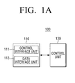
- FIG. 1A is a schematic block diagram illustrating a configuration of an image forming apparatus according to an exemplary embodiment.
- the image forming apparatus 100 may include a Universal Serial Bus (USB) interface unit 110 and a control unit 120.
- the image forming apparatus 100 may be printers, copiers, scanners, facsimile machines, or multifunction peripherals (MFPs) having combined functions in a single device.
- USB Universal Serial Bus
- MFPs multifunction peripherals
- the USB interface unit 110 performs USB communication with at least one external device.
- the at least one external device may be host devices such as personal computers (PCs).
- PCs personal computers
- the USB interface unit 110 may include a control interface unit 111 to perform USB control communication with the at least one external device, and a data interface unit 112 to perform USB data communication with the at least one external device.
- USB interface unit 110 may be implemented as an end point which is a logical port. Detailed description is given below with reference to the following drawings.
- the control unit 120 controls the overall operation of the image forming apparatus 100, and in particular, controls a low power mode and a normal mode of the image forming apparatus 100.
- control unit 120 In the low power mode, the control unit 120 performs an event according to a signal input through the control interface unit 111, and in the normal mode, the control unit 120 performs an event according to a signal input through the control interface unit 111 and the data interface unit 112.
- control unit 120 In the low power mode, if the control unit 120 receives a signal through the data interface unit 112, the control unit 120 enters the normal mode.
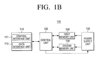
- FIG. 1B is a block diagram illustrating a detailed configuration of the image forming apparatus shown in FIG. 1A .
- the image forming apparatus 100 may include a USB interface unit 110, a control unit 120, a first memory unit 130, a second memory unit 140, and a power supply unit 150.
- a USB interface unit 110 may include a USB interface unit 110, a control unit 120, a first memory unit 130, a second memory unit 140, and a power supply unit 150.
- the components of the image forming apparatus 100 of FIG. 1B detailed description of components overlapping the image forming apparatus 100 of FIG. 1A is not repeated.
- the control unit 120 converts the normal mode into the low power mode if a preset condition is satisfied, for example, if there is no command for a preset period of time. This is merely an example, and there may be diverse conditions for mode conversion.
- control unit 120 converts the low power mode into the normal mode if a preset condition is satisfied. For example, when the image forming apparatus 100 is a printer, if a panel key is input, a printing service is requested, of a fax rings, the control unit 120 converts the low power mode into the normal mode.
- the control unit 120 converts the normal mode into the low power mode, the control unit 120 copies a program to control the low power mode from the first memory unit 130 into an executable area of the second memory unit 140.
- the first memory unit 130 is main memory which may be implemented as, for example, dynamic random access memory (DRAM).
- the first memory unit 130 may store a program capable of supporting USB communication in the normal mode, applications, etc, including a USB driver.
- the second memory unit 140 may store a program capable of supporting the low power mode, applications, and may be implemented as static random access memory (SRAM).
- SRAM static random access memory
- the program to control the low power mode includes the USB driver.
- the USB driver includes only a routine which is in charge of processing control end point and a routine which is needed to be woken to return to the normal mode.
- the program to control the low power mode requires lower capacity compared with the USB program which is stored in the first memory unit 130.
- control unit 120 cuts off the power supply to most of system modules and the image forming apparatus 100 enters the low power mode.
- control unit 120 checks whether or not interrupt is caused by the control interface unit 111 or the data interface unit 112.
- control unit 120 processes a corresponding service.
- the control unit 120 If interrupt is not caused by the control interface unit 111 but caused by the data interface unit 112, the control unit 120 reads printing data, stores the printer data in the second memory unit 140, returns to the normal mode, and processes a corresponding service.
- the control unit 120 may return to the normal mode and store printing data in the first memory unit 130.
- FIFO First In First Out
- DMA direct memory access
- the control unit 120 stores data from the second memory unit 140 into the first memory unit 130 which is accessible by the USB driver in the normal mode. In this case, all hardware becomes active and if the USB driver begins its operation, the control unit 120 processes the interrupt and subsequently following events.
- the image forming apparatus 100 processes only a service input by the control interface unit 111. This is because the second memory unit 140 has limited storage capacity.
- the power supply unit 150 supplies power to the first memory unit 130 and the second memory unit 140 according to operation of the control unit 120.
- the power supply unit 150 supports the low power mode by cutting off power to the first memory unit 130 and maintaining power supply to the second memory unit 140.
- the control unit 120 may be implemented as only a main controller which supports both the normal mode and the low power mode, or implemented separately as a main controller, which supports the normal mode, and a sub-controller, which supports the low power mode.
- the control unit 120 is implemented as only a main controller, that is, if main firmware related to control of the normal mode and micro firmware related to control of the low power mode are implemented on a single chip, the low power mode may be implemented by lowering frequency of the main controller as described above or configuring a gated clock in designing the main controller and thus cutting off clock input for blocks which do not operate in the low power mode.
- the micro firmware may be built in an inner memory (SRAM) of the main controller. The SRAM maintains data without refresh, and is thus faster than the DRAM in reaction rate. As a result, fast conversion is enabled from the low power mode to the normal mode.
- control unit 120 is implemented separately as a main controller and a sub-controller, that is, if main firmware related to control of the normal mode and micro firmware related to control of the low power mode are implemented on respective chips, the low power mode may be implemented by supplying power only to the sub-controller.
- control unit 120 is implemented separately as a main controller and a sub-controller for convenience of description.
- FIG. 2 is a block diagram illustrating the relation between the image forming apparatus shown in FIG. 1B and a host device. Among the components shown in FIG. 2 , detailed description of components overlapping components described in FIG. 1B is not repeated.
- the host device 200 may be implemented as a personal computer (PC) or a user terminal device such as personal digital assistants (PDAs) and portable media players (PMPs).
- PC personal computer
- PDAs personal digital assistants
- PMPs portable media players
- the host device 200 may include an application 210 and a host controller 220.
- the application 210 may be software supporting a USB function in an operating system (OS).
- OS operating system
- the host controller 220 indicates a USB bus interface of the host device 200, and includes all software and hardware which enable a USB device (that is, the image forming apparatus 100) to be connected to the host device 200.
- the host device 200 may further include a printer driver (unnumbered) which converts printing data written using an application program into a printer language which can be interpreted by the image forming apparatus 100.
- the printer driver may be included in the host controller 220.
- the host device 200 may further include general components constituting host devices such as an input unit (not shown) and a display unit (not shown).
- An end point is a logical port and is an end of flow of communication, which has a unique identification (ID).
- An end point includes information regarding data transmission direction (an input end point and an output end point).
- An end point may include an access frequency of a bus, requirements in delay of access of a bus, requirements for bandwidth, the number of end points, requirements for error handling, the maximum size of packet which the end point can accept, the type of transmission, the transmission direction, etc.
- a pipe is the link between an end point in a device and software in a host.
- a pipe is divided into a stream pipe and a message pipe according to features.
- a stream pipe and a message pipe are different and exclusive.
- a stream pipe has no defined USB format and supports one-way communication.
- a message pipe has a defined USB format and supports two-way communication.
- the image forming apparatus 100 communicates with the host device 200 through a USB, and has a control end point 111 (the control interface unit which is described above) and a plurality of end points 112 and 113 (the data interface unit which is described above) in the USB interface unit 110.
- the end points except for the control end point 111 are slightly different according to a transmission method, but may be simply considered as logical ports for data transmission and are thus referred to hereinafter as data end points.
- the control end point 111 is a logical port to determine whether or not the host device 200 is connected to the image forming apparatus 100 through a series of procedures called enumeration and, if connected, to obtain information regarding the image forming apparatus 100 or set the image forming apparatus 100 to be communicable with the host device 200. That is, the control end point 111 is used while enumeration is performed or a device on a bus operates (when the device is recognized). Accordingly, the control end point 111 is a basic end point to be in charge of connection/removal/recognition of a device, so any device should have one. In addition, the control end point 111 should be always controllable.
- the control end point 111 uses a message pipe unlike the data end points, and thus enables two-way transmission.
- the data end points 112 and 113 are used for data transmission, and may be at least one of bulk type IN/OUT end points, isochronous type IN/OUT end points, and interrupt type IN/OUT end points.
- a bulk type IN/OUT end point exactly transmits comparatively a huge amount of data, with a total disregard for time, and retransmits data if a transmission error may occur in the bus.
- a bulk type IN/OUT end point may be used for data transmission of a storage device such as a hard disk.
- a bulk type IN/OUT end point uses a stream pipe, and thus supports one-way transmission.
- An isochronous type IN/OUT end point is used mainly for devices which values real-time communication such as audios above everything else, uses a stream pipe, and thus supports one-way transmission.
- An interrupt type IN/OUT end point is used mainly for devices which need periodical signal transmission and reception, uses a stream pipe, and thus supports one-way transmission.
- a bulk type IN/OUT end point may be used.
- the data end points 112 and 113 may select the number and the direction according to feature of interface.
- a manufacturer may selectively determine the number and function of the data end points 112 and 113 according to specifications of the device.
- FIG. 3 For example, a configuration of end points of a multifunction peripheral is shown in FIG. 3 .
- an OUT end point 112'-2 of the interface I 112' is an end point for receiving printing data from a host device 200'
- an IN end point 113'-1 of the interface II 113' is an end point for transmitting scanned data from the host device 200'.
- the host device 200' includes first and second host controllers 220'-1 and 220'-2.
- the first and second host controllers 220'-1 and 220'-2 may include device drivers I and II, respectively (unnumbered).
- a main controller 121 controls the normal mode.
- the main controller 121 controls a basic function of an image forming apparatus 100' such as copying, scanning, faxing, etc in the normal mode.
- the main controller 121 converts the normal mode into the low power mode if a preset condition is satisfied, for example, if there is no command for a preset period of time. This is merely an example. When a specific user command is input, the main controller 121 may convert the normal mode into the low power mode.
- the main controller 121 converts the normal mode into the low power mode.
- the main control unit 121 copies a program to control the low power mode from the first memory unit 130 into an executable area of the second memory unit 140.
- the first memory unit 130 is main memory which may store a program required for the overall operation of the image forming apparatus 100, applications, etc.
- the first memory unit 130 may be implemented as DRAM and the second memory unit 140 may be implemented as SRAM.
- the program to control the low power mode includes the USB driver.
- the USB driver includes only a routine which is in charge of processing control end point and a routine which is needed to be woken to return to the normal mode.
- the USB program which is stored in the second memory unit 140 requires lower capacity compared with the USB program which is stored in the first memory unit 130, and can thus be implemented as low capacity memory.
- the sub-controller 122 checks whether or not interrupt is caused by the control end point 111 or the data end point 112.
- the sub-controller 122 processes a corresponding event by executing the program and application stored in the second memory unit 140.
- the control unit 120 If interrupt is not caused by the control end point 111 but caused by the data end point 112, the control unit 120 reads printing data, stores the printer data in the second memory unit 140, returns to the normal mode, and processes a corresponding service.
- the image forming apparatus 100 may return to the normal mode and store printing data in the first memory unit 130.
- FIFO First In First Out
- DMA direct memory access
- the image forming apparatus 100 stores data from the second memory unit 140 into the first memory unit 130 which is accessible by the USB driver in the normal mode. In this case, all hardware becomes active and if the USB driver begins its operation, the image forming apparatus 100 processes the interrupt and subsequently following events.
- FIGS. 1 to 3 and the disposition thereof are merely an exemplary embodiment, so some elements may be deleted and more elements can be added according to circumstances. Their disposition also may change.
- FIG. 4 illustrates a USB packet analysis table according to an exemplary embodiment.
- the printer driver 220 of the host device 200 transmits a manufacturer limitation or class limitation request to the image forming apparatus 100 through the control end point (end point 0: ENDP 0) on occasion.
- the subsequently following bulk transmission is a printing command through end point 1 (see reference letter "A").
- Such a manufacture limitation request may vary according to the manufacturer.
- the sub-controller processes requests for the control end point from Transfer 48 to Transfer 64. Subsequently, if the image forming apparatus 100 receives a printing command such as Transfer 65 through end point 1, the low power mode changes to the normal mode and the main controller processes a corresponding event.
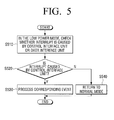
- FIG. 5 is a flow chart illustrating a method for operating an image forming apparatus in a low power mode according to an exemplary embodiment of the present invention.
- operation S510 in the low power mode, it is checked whether or not interrupt is caused by the USB interface unit.
- the image forming apparatus performs all events requested through both the control interface unit and the data interface unit.
- the control interface unit performs USB control communication and may be a control end point.
- the data interface unit performs USB data communication and may be a data end point, that is, all end points other than a control end point.
- the control end point is a logical port to determine whether or not the host device is connected to the image forming apparatus through a series of procedures called enumeration and, if connected, to obtain information regarding the image forming apparatus or set the image forming apparatus to be communicable with the host device. That is, the control end point is used while enumeration is performed or a device on a bus operates (when the device is recognized).
- the control end point uses a message pipe unlike the data end point, and thus enables two-way transmission.
- the data end point is used for data transmission, and may be at least one of bulk type IN/OUT end points, isochronous type IN/OUT end points, and interrupt type IN/OUT end points.
- the data end point uses a stream pipe, and thus supports one-way transmission.
- the normal mode is controlled by the main controller and the low power mode is controlled by the sub-controller.
- the power supply is cut off to the external memory used in the normal mode and the power supply is maintained to the internal memory used in the low power mode.
- USB communication is enabled normally.
- cost for an additional SRAM may be saved and the low power mode may be effectively implemented.
- an image forming apparatus is described, but this is merely an example.
- the technical idea of the present invention may also be applied to any kinds of electronic devices capable of USB communication.
Landscapes
- Engineering & Computer Science (AREA)
- Theoretical Computer Science (AREA)
- General Engineering & Computer Science (AREA)
- Physics & Mathematics (AREA)
- General Physics & Mathematics (AREA)
- Multimedia (AREA)
- Signal Processing (AREA)
- Accessory Devices And Overall Control Thereof (AREA)
- Facsimiles In General (AREA)
- Power Sources (AREA)
Abstract
Description
- The present invention relates to an image forming apparatus and a low power driving method thereof.
- A low power mode is a mode in which the power supply to most of the modules is shut down or minimized so as to minimize power consumption when a system is inactive. In order to implement lower standby power, the power supply may be shut down to main memory (in general, external dynamic random access memory (DRAM)), or the main memory may enter self refresh state and internal memory (in general, internal static random access memory (SRAM)) which is not in use in system on chip (SOC) drives a program. SRAM usually uses small quantity of memory of approximately 128 kilobytes.
- However, as in a Universal Serial Bus (USB) driver for printers or large-capacity storage devices, if bulk data transmission is required or the number of supportable interfaces is increased, space taken up by a stack is increased, so it is difficult to implement all functions of the USB driver in a small-capacity SRAM.
- In addition, it is inefficient to apply large-capacity SRAM of a high cost.
- If a device which is used as a USB device cuts off the power supply to the external DRAM so as to enter the low power mode, a USB driver in the external DRAM also stops its operation, so the device cannot communicate with a USB and a host device. In particular, if the host device, for example, a personal computer (PC) sends a specific operation command, for example, a printing command to the device through the USB, the host device cannot perform the command (that is, the PC recognizes that connection with the device is cut.). Accordingly, in a related art, the external DRAM should operate normally in the low power mode.
- If power is continuously supplied to the external DRAM, standby power is consumed. To consume lower power, if the power supply is cut off to the external DRAM, the USB driver does not operate, so communication through the USB may be impossible. In this case, if a program which monitors the state of the device using the USB approaches, it is determined that the device is turned off, thereby causing inconvenience. For example, if the PC is connected to the printer through the USB and has a printer monitoring program, when the DRAM of the printer is turned off and the USB driver does not operate, the PC may recognize that the printer is in an abnormal state or connection with the printer is cut off.
- Therefore, there is a need for a low power driving method of an image forming apparatus.
- Aspects provide an image forming apparatus and a low power driving method thereof.
- Additional aspects and/or advantages will be set forth in part in the description which follows and, in part, will be apparent from the description, or may be learned by practice of the invention.
- In accordance with an exemplary embodiment, there is provided an image forming apparatus including a control interface unit to perform Universal Serial Bus (USB) control communication, a data interface unit to perform USB data communication, and a control unit to perform an event in a low power mode according to a signal input through the control interface unit, and to perform an event in a normal mode according to a signal input through the control interface unit and the data interface unit.
- According to an aspect, in the low power mode, if a signal is input through the data interface unit, the control unit may convert the low power mode into the normal mode.
- According to an aspect, the image forming apparatus may further include a first memory unit to be used in the normal mode, a second memory unit to be used in the low power mode, and a power supply unit to supply power to the first memory unit and the second memory unit, wherein if the image forming apparatus operates in the low power mode, the control unit controls the power supply unit to cut off the power supply to the first memory unit.
- According to an aspect, the control unit may include a main controller to control operation of the image forming apparatus in the normal mode, and a sub-controller to control operation of the image forming apparatus in the low power mode.
- According to an aspect, in the low power mode, the sub-controller may check whether or not interrupt is caused by the control interface unit or the data interface unit.
- According to an aspect, if interrupt is caused by the control interface unit, the sub-controller may process an event related to the interrupt, and if interrupt is caused by the data interface unit, the sub-controller may convert the low power mode into the normal mode.
- According to an aspect, the control interface unit may be a control end point, and the data interface unit may be a bulk type IN/OUT end point.
- In accordance with another exemplary embodiment, there is provided a low power driving method of an image forming apparatus which includes a control interface unit to perform Universal Serial Bus (USB) control communication, and a data interface unit to perform USB data communication, the method including checking whether or not a signal is input though the control interface unit or the data interface unit in a low power mode, and if a signal is input through the control interface unit, performing an event according to the input signal, and if a signal is input through the data interface unit, converting the low power mode into a normal mode.
- According to an aspect, the method may further include if the image forming apparatus operates in the low power mode, cutting off the power supply to a first memory unit which is used in the normal mode, and maintaining the power supply to a second memory unit which is used in the low power mode.
- According to an aspect, the method may further include if the image forming apparatus operates in the low power mode, cutting off the power supply to a main controller which controls operation of the image forming apparatus in the normal mode, and maintaining the power supply to a sub-controller which controls operation of the image forming apparatus in the low power mode.
- According to an aspect, the control interface unit may be a control end point, and the data interface unit may be a bulk type IN/OUT end point.
- In addition to the exemplary embodiments and aspects as described above, further aspects and embodiments will be apparent by reference to the drawings and by study of the following descriptions.
- A better understanding of the present disclosure will become apparent from the following detailed description of exemplary embodiments and the claims when read in connection with the accompanying drawings, all forming a part of the disclosure of this invention. While the following written and illustrated disclosure focuses on disclosing exemplary embodiments, it should be clearly understood that the same is by way of illustration and example only and that the invention is not limited thereto. The spirit and scope of the present invention are limited only by the terms of the appended claims.
- The following represents brief descriptions of the drawings, wherein:
-
FIGs. 1A and1B are block diagrams illustrating a configuration of an image forming apparatus according to an exemplary embodiment; -
FIG. 2 is a block diagram illustrating the relation between the image forming apparatus shown inFIG. 1B and a host device; -
FIG. 3 is a block diagram illustrating a configuration of an end point according to an exemplary embodiment; -
FIG. 4 illustrates a USB packet analysis table according to an exemplary embodiment; and -
FIG. 5 is a flow chart illustrating a method for operating an image forming apparatus in a low power mode according to an exemplary embodiment. - Reference will now be made in detail to the embodiments, examples of which are illustrated in the accompanying drawings, wherein like reference numerals refer to the like elements throughout. The embodiments are described below in order to explain the present invention by referring to the figures.
-
FIG. 1A is a schematic block diagram illustrating a configuration of an image forming apparatus according to an exemplary embodiment. - Referring to
FIG. 1A , theimage forming apparatus 100 may include a Universal Serial Bus (USB)interface unit 110 and acontrol unit 120. Theimage forming apparatus 100 may be printers, copiers, scanners, facsimile machines, or multifunction peripherals (MFPs) having combined functions in a single device. - The
USB interface unit 110 performs USB communication with at least one external device. The at least one external device may be host devices such as personal computers (PCs). - The
USB interface unit 110 may include acontrol interface unit 111 to perform USB control communication with the at least one external device, and adata interface unit 112 to perform USB data communication with the at least one external device. - More specifically, the
USB interface unit 110 may be implemented as an end point which is a logical port. Detailed description is given below with reference to the following drawings. - The
control unit 120 controls the overall operation of theimage forming apparatus 100, and in particular, controls a low power mode and a normal mode of theimage forming apparatus 100. - In the low power mode, the
control unit 120 performs an event according to a signal input through thecontrol interface unit 111, and in the normal mode, thecontrol unit 120 performs an event according to a signal input through thecontrol interface unit 111 and thedata interface unit 112. - In the low power mode, if the
control unit 120 receives a signal through thedata interface unit 112, thecontrol unit 120 enters the normal mode. -
FIG. 1B is a block diagram illustrating a detailed configuration of the image forming apparatus shown inFIG. 1A . - Referring to
FIG. 1B , theimage forming apparatus 100 may include aUSB interface unit 110, acontrol unit 120, afirst memory unit 130, asecond memory unit 140, and apower supply unit 150. Among the components of theimage forming apparatus 100 ofFIG. 1B , detailed description of components overlapping theimage forming apparatus 100 ofFIG. 1A is not repeated. - The
control unit 120 converts the normal mode into the low power mode if a preset condition is satisfied, for example, if there is no command for a preset period of time. This is merely an example, and there may be diverse conditions for mode conversion. - In addition, the
control unit 120 converts the low power mode into the normal mode if a preset condition is satisfied. For example, when theimage forming apparatus 100 is a printer, if a panel key is input, a printing service is requested, of a fax rings, thecontrol unit 120 converts the low power mode into the normal mode. - If the
control unit 120 converts the normal mode into the low power mode, thecontrol unit 120 copies a program to control the low power mode from thefirst memory unit 130 into an executable area of thesecond memory unit 140. Thefirst memory unit 130 is main memory which may be implemented as, for example, dynamic random access memory (DRAM). Thefirst memory unit 130 may store a program capable of supporting USB communication in the normal mode, applications, etc, including a USB driver. - The
second memory unit 140 may store a program capable of supporting the low power mode, applications, and may be implemented as static random access memory (SRAM). - The program to control the low power mode includes the USB driver. The USB driver includes only a routine which is in charge of processing control end point and a routine which is needed to be woken to return to the normal mode. The program to control the low power mode requires lower capacity compared with the USB program which is stored in the
first memory unit 130. - If copying the program to control the low power mode is complete, the
control unit 120 cuts off the power supply to most of system modules and theimage forming apparatus 100 enters the low power mode. - In the low power mode, the
control unit 120 checks whether or not interrupt is caused by thecontrol interface unit 111 or thedata interface unit 112. - If interrupt is caused by the
control interface unit 111, thecontrol unit 120 processes a corresponding service. - If interrupt is not caused by the
control interface unit 111 but caused by thedata interface unit 112, thecontrol unit 120 reads printing data, stores the printer data in thesecond memory unit 140, returns to the normal mode, and processes a corresponding service. This is merely an exemplary embodiment. According to whether the USB is in First In First Out (FIFO) mode or in direct memory access (DMA) mode, thecontrol unit 120 may return to the normal mode and store printing data in thefirst memory unit 130. - More specifically, if interrupt is caused by the
data interface unit 112, that is, if a specific operation command is input by thedata interface unit 112, thecontrol unit 120 stores data from thesecond memory unit 140 into thefirst memory unit 130 which is accessible by the USB driver in the normal mode. In this case, all hardware becomes active and if the USB driver begins its operation, thecontrol unit 120 processes the interrupt and subsequently following events. - That is, in the low power mode, the
image forming apparatus 100 according to the exemplary embodiment processes only a service input by thecontrol interface unit 111. This is because thesecond memory unit 140 has limited storage capacity. - The
power supply unit 150 supplies power to thefirst memory unit 130 and thesecond memory unit 140 according to operation of thecontrol unit 120. - More specifically, the
power supply unit 150 supports the low power mode by cutting off power to thefirst memory unit 130 and maintaining power supply to thesecond memory unit 140. - The
control unit 120 may be implemented as only a main controller which supports both the normal mode and the low power mode, or implemented separately as a main controller, which supports the normal mode, and a sub-controller, which supports the low power mode. - If the
control unit 120 is implemented as only a main controller, that is, if main firmware related to control of the normal mode and micro firmware related to control of the low power mode are implemented on a single chip, the low power mode may be implemented by lowering frequency of the main controller as described above or configuring a gated clock in designing the main controller and thus cutting off clock input for blocks which do not operate in the low power mode. In this case, the micro firmware may be built in an inner memory (SRAM) of the main controller. The SRAM maintains data without refresh, and is thus faster than the DRAM in reaction rate. As a result, fast conversion is enabled from the low power mode to the normal mode. - To the contrary, if the
control unit 120 is implemented separately as a main controller and a sub-controller, that is, if main firmware related to control of the normal mode and micro firmware related to control of the low power mode are implemented on respective chips, the low power mode may be implemented by supplying power only to the sub-controller. - In the exemplary embodiment, the
control unit 120 is implemented separately as a main controller and a sub-controller for convenience of description. -
FIG. 2 is a block diagram illustrating the relation between the image forming apparatus shown inFIG. 1B and a host device. Among the components shown inFIG. 2 , detailed description of components overlapping components described inFIG. 1B is not repeated. - The
host device 200 may be implemented as a personal computer (PC) or a user terminal device such as personal digital assistants (PDAs) and portable media players (PMPs). - The
host device 200 may include anapplication 210 and ahost controller 220. - The
application 210 may be software supporting a USB function in an operating system (OS). - The
host controller 220 indicates a USB bus interface of thehost device 200, and includes all software and hardware which enable a USB device (that is, the image forming apparatus 100) to be connected to thehost device 200. - The
host device 200 may further include a printer driver (unnumbered) which converts printing data written using an application program into a printer language which can be interpreted by theimage forming apparatus 100. The printer driver may be included in thehost controller 220. In addition, thehost device 200 may further include general components constituting host devices such as an input unit (not shown) and a display unit (not shown). - Hereinafter, general concept of an end point and a pipe is briefly described for better understanding of the embodiments.
- An end point is a logical port and is an end of flow of communication, which has a unique identification (ID). An end point includes information regarding data transmission direction (an input end point and an output end point). An end point may include an access frequency of a bus, requirements in delay of access of a bus, requirements for bandwidth, the number of end points, requirements for error handling, the maximum size of packet which the end point can accept, the type of transmission, the transmission direction, etc.
- A pipe is the link between an end point in a device and software in a host. A pipe is divided into a stream pipe and a message pipe according to features. A stream pipe and a message pipe are different and exclusive. A stream pipe has no defined USB format and supports one-way communication. A message pipe has a defined USB format and supports two-way communication.
- Detailed description of an end point and a pipe is omitted here since USB specifications provide description thereof in detail.
- The
image forming apparatus 100 communicates with thehost device 200 through a USB, and has a control end point 111 (the control interface unit which is described above) and a plurality ofend points 112 and 113 (the data interface unit which is described above) in theUSB interface unit 110. The end points except for thecontrol end point 111 are slightly different according to a transmission method, but may be simply considered as logical ports for data transmission and are thus referred to hereinafter as data end points. - The
control end point 111 is a logical port to determine whether or not thehost device 200 is connected to theimage forming apparatus 100 through a series of procedures called enumeration and, if connected, to obtain information regarding theimage forming apparatus 100 or set theimage forming apparatus 100 to be communicable with thehost device 200. That is, thecontrol end point 111 is used while enumeration is performed or a device on a bus operates (when the device is recognized). Accordingly, thecontrol end point 111 is a basic end point to be in charge of connection/removal/recognition of a device, so any device should have one. In addition, thecontrol end point 111 should be always controllable. - The
control end point 111 uses a message pipe unlike the data end points, and thus enables two-way transmission. - The
data end points - A bulk type IN/OUT end point exactly transmits comparatively a huge amount of data, with a total disregard for time, and retransmits data if a transmission error may occur in the bus. For example, a bulk type IN/OUT end point may be used for data transmission of a storage device such as a hard disk. In addition, a bulk type IN/OUT end point uses a stream pipe, and thus supports one-way transmission.
- An isochronous type IN/OUT end point is used mainly for devices which values real-time communication such as audios above everything else, uses a stream pipe, and thus supports one-way transmission.
- An interrupt type IN/OUT end point is used mainly for devices which need periodical signal transmission and reception, uses a stream pipe, and thus supports one-way transmission.
- In general, since the
image forming apparatus 100 requires large quantity of transmission, a bulk type IN/OUT end point may be used. - The
data end points data end points - For example, a configuration of end points of a multifunction peripheral is shown in
FIG. 3 . - In
FIG. 3 , if it is assumed that an interface I 112' is for a printer and an interface II 113' is for a scanner, an OUT end point 112'-2 of the interface I 112' is an end point for receiving printing data from a host device 200', and an IN end point 113'-1 of the interface II 113' is an end point for transmitting scanned data from the host device 200'. InFIG. 3 , the host device 200' includes first and second host controllers 220'-1 and 220'-2. The first and second host controllers 220'-1 and 220'-2 may include device drivers I and II, respectively (unnumbered). - A
main controller 121 controls the normal mode. - That is, the
main controller 121 controls a basic function of an image forming apparatus 100' such as copying, scanning, faxing, etc in the normal mode. - In addition, the
main controller 121 converts the normal mode into the low power mode if a preset condition is satisfied, for example, if there is no command for a preset period of time. This is merely an example. When a specific user command is input, themain controller 121 may convert the normal mode into the low power mode. - That is, if the
image forming apparatus 100 does not perform any job or if there is no operating command such as copying, scanning, and faxing which can be input using diverse user interfaces such as a panel on theimage forming apparatus 100, a USB or a network for a preset period of time, themain controller 121 converts the normal mode into the low power mode. - If the
main controller 121 converts the normal mode into the low power mode, themain control unit 121 copies a program to control the low power mode from thefirst memory unit 130 into an executable area of thesecond memory unit 140. Thefirst memory unit 130 is main memory which may store a program required for the overall operation of theimage forming apparatus 100, applications, etc. Thefirst memory unit 130 may be implemented as DRAM and thesecond memory unit 140 may be implemented as SRAM. - The program to control the low power mode includes the USB driver. The USB driver includes only a routine which is in charge of processing control end point and a routine which is needed to be woken to return to the normal mode. The USB program which is stored in the
second memory unit 140 requires lower capacity compared with the USB program which is stored in thefirst memory unit 130, and can thus be implemented as low capacity memory. - If copying the program to control the low power mode is complete, the power supply to most of system modules including the
first memory unit 130 is cut off and theimage forming apparatus 100 enters the low power mode. - In the low power mode, the sub-controller 122 checks whether or not interrupt is caused by the
control end point 111 or thedata end point 112. - If interrupt is caused by the
control end point 111, the sub-controller 122 processes a corresponding event by executing the program and application stored in thesecond memory unit 140. - If interrupt is not caused by the
control end point 111 but caused by thedata end point 112, thecontrol unit 120 reads printing data, stores the printer data in thesecond memory unit 140, returns to the normal mode, and processes a corresponding service. This is merely an exemplary embodiment. According to whether the USB is in First In First Out (FIFO) mode or in direct memory access (DMA) mode, theimage forming apparatus 100 may return to the normal mode and store printing data in thefirst memory unit 130. - More specifically, if interrupt is caused by the
data end point 112, that is, if a specific operation command is input by thedata end point 112, theimage forming apparatus 100 stores data from thesecond memory unit 140 into thefirst memory unit 130 which is accessible by the USB driver in the normal mode. In this case, all hardware becomes active and if the USB driver begins its operation, theimage forming apparatus 100 processes the interrupt and subsequently following events. - The components illustrated in
FIGS. 1 to 3 and the disposition thereof are merely an exemplary embodiment, so some elements may be deleted and more elements can be added according to circumstances. Their disposition also may change. -
FIG. 4 illustrates a USB packet analysis table according to an exemplary embodiment. - Referring to
FIG. 4 , theprinter driver 220 of thehost device 200 transmits a manufacturer limitation or class limitation request to theimage forming apparatus 100 through the control end point (end point 0: ENDP 0) on occasion. The subsequently following bulk transmission is a printing command through end point 1 (see reference letter "A"). This means that in the low power mode, requests may be continuously generated through the control end point. Such a manufacture limitation request may vary according to the manufacturer. - If the
image forming apparatus 100 receives requests as shown inFIG. 4 , the sub-controller processes requests for the control end point from Transfer 48 to Transfer 64. Subsequently, if theimage forming apparatus 100 receives a printing command such asTransfer 65 throughend point 1, the low power mode changes to the normal mode and the main controller processes a corresponding event. -
FIG. 5 is a flow chart illustrating a method for operating an image forming apparatus in a low power mode according to an exemplary embodiment of the present invention. - Referring to
FIG. 5 , in operation S510, in the low power mode, it is checked whether or not interrupt is caused by the USB interface unit. - In operation S520, if interrupt is caused by the USB interface unit, it is determined whether or not the interrupt signal is caused by the control interface unit.
- In operation S530, if the interrupt signal is caused by the control interface unit, the image forming apparatus processes a corresponding event.
- In operation S540, if the interrupt signal is not caused by the control interface unit but caused by the data interface unit, the image forming apparatus returns to the normal mode.
- Subsequently, in the normal mode, the image forming apparatus performs all events requested through both the control interface unit and the data interface unit.
- The control interface unit performs USB control communication and may be a control end point.
- The data interface unit performs USB data communication and may be a data end point, that is, all end points other than a control end point.
- The control end point is a logical port to determine whether or not the host device is connected to the image forming apparatus through a series of procedures called enumeration and, if connected, to obtain information regarding the image forming apparatus or set the image forming apparatus to be communicable with the host device. That is, the control end point is used while enumeration is performed or a device on a bus operates (when the device is recognized). The control end point uses a message pipe unlike the data end point, and thus enables two-way transmission.
- The data end point is used for data transmission, and may be at least one of bulk type IN/OUT end points, isochronous type IN/OUT end points, and interrupt type IN/OUT end points. The data end point uses a stream pipe, and thus supports one-way transmission.
- The normal mode is controlled by the main controller and the low power mode is controlled by the sub-controller.
- Applications and programs which are needed to operate in the normal mode may be stored in external memory such as DRAM.
- Applications and programs which are needed to operate in the low power mode may be stored in internal memory such as DRAM.
- If the image forming apparatus operates in the low power mode, the power supply is cut off to the external memory used in the normal mode and the power supply is maintained to the internal memory used in the low power mode.
- As described above, according to the exemplary embodiment of the present invention, although the power supply is cut off to the main memory in which the USB driver operates, USB communication is enabled normally. Using small-capacity SRAM in the SOC, cost for an additional SRAM may be saved and the low power mode may be effectively implemented.
- In the exemplary embodiment of the present invention, an image forming apparatus is described, but this is merely an example. The technical idea of the present invention may also be applied to any kinds of electronic devices capable of USB communication.
- Although a few embodiments of the present invention have been shown and described, it would be appreciated by those skilled in the art that changes may be made in these embodiments without departing from the principles and spirit of the invention, the scope of which is defined in the claims and their equivalents.
Claims (11)
- An image forming apparatus, comprising:a control interface unit to perform Universal Serial Bus (USB) control communication;a data interface unit to perform USB data communication; anda control unit to perform an event in a low power mode according to a signal input through the control interface unit, and to perform an event in a normal mode according to a signal input through the control interface unit and the data interface unit.
- The image forming apparatus according to claim 1, wherein in the low power mode, if a signal is input through the data interface unit, the control unit converts the low power mode into the normal mode.
- The image forming apparatus according to claim 1, further comprising:a first memory unit to be used in the normal mode;a second memory unit to be used in the low power mode; anda power supply unit to supply power to the first memory unit and the second memory unit, wherein if the image forming apparatus operates in the low power mode, the control unit controls the power supply unit to cut off the power supply to the first memory unit.
- The image forming apparatus according to claim 3, wherein the control unit comprises:a main controller to control operation of the image forming apparatus in the normal mode; anda sub-controller to control operation of the image forming apparatus in the low power mode.
- The image forming apparatus according to claim 4, wherein in the low power mode, the sub-controller checks whether or not interrupt is caused by the control interface unit or the data interface unit.
- The image forming apparatus according to claim 5, wherein if interrupt is caused by the control interface unit, the sub-controller processes an event related to the interrupt, and if interrupt is caused by the data interface unit, the sub-controller converts the low power mode into the normal mode.
- The image forming apparatus according to claim 1, wherein the control interface unit is a control end point, and the data interface unit is a bulk type IN/OUT end point.
- A low power driving method of an image forming apparatus which comprises a control interface unit to perform Universal Serial Bus (USB) control communication, and a data interface unit to perform USB data communication, the method comprising:checking whether or not a signal is input though the control interface unit or the data interface unit in a low power mode; andif a signal is input through the control interface unit, performing an event according to the input signal, and if a signal is input through the data interface unit, converting the low power mode into a normal mode.
- The method according to claim 8, further comprising:if the image forming apparatus operates in the low power mode, cutting off the power supply to a first memory unit which is used in the normal mode, and maintaining the power supply to a second memory unit which is used in the low power mode.
- The method according to claim 8, further comprising:if the image forming apparatus operates in the low power mode, cutting off the power supply to a main controller which controls operation of the image forming apparatus in the normal mode, and maintaining the power supply to a sub-controller which controls operation of the image forming apparatus in the low power mode.
- The method according to claim 8, wherein the control interface unit is a control end point, and the data interface unit is a bulk type IN/OUT end point.
Applications Claiming Priority (1)
| Application Number | Priority Date | Filing Date | Title |
|---|---|---|---|
| KR20090084921 | 2009-09-09 |
Publications (2)
| Publication Number | Publication Date |
|---|---|
| EP2302520A1 true EP2302520A1 (en) | 2011-03-30 |
| EP2302520B1 EP2302520B1 (en) | 2017-06-14 |
Family
ID=43128248
Family Applications (1)
| Application Number | Title | Priority Date | Filing Date |
|---|---|---|---|
| EP10157629.6A Active EP2302520B1 (en) | 2009-09-09 | 2010-03-24 | Image forming apparatus and low power driving method thereof |
Country Status (4)
| Country | Link |
|---|---|
| US (2) | US9141574B2 (en) |
| EP (1) | EP2302520B1 (en) |
| KR (1) | KR101203145B1 (en) |
| ES (1) | ES2448799T3 (en) |
Cited By (3)
| Publication number | Priority date | Publication date | Assignee | Title |
|---|---|---|---|---|
| EP2757470A1 (en) * | 2013-01-17 | 2014-07-23 | Samsung Electronics Co., Ltd | Image forming apparatus, method of connecting with external device thereof, and computer-readable recording medium |
| US9015506B2 (en) | 2011-05-04 | 2015-04-21 | Samsung Electronics Co., Ltd. | Image forming apparatus and method for controlling the same |
| CN109581935A (en) * | 2018-12-29 | 2019-04-05 | 广州市易售宝互联网科技有限公司 | A kind of All-in-One intelligence account opening device control system |
Families Citing this family (11)
| Publication number | Priority date | Publication date | Assignee | Title |
|---|---|---|---|---|
| EP2302521B1 (en) | 2009-09-09 | 2012-02-08 | Samsung Electronics Co., Ltd. | Image forming apparatus and power saving driving method thereof |
| JP5446943B2 (en) * | 2010-01-29 | 2014-03-19 | ソニー株式会社 | Printing system and printer apparatus control method |
| US9128718B1 (en) * | 2010-03-29 | 2015-09-08 | Amazon Technologies, Inc. | Suspend using internal rewriteable memory |
| US9336342B2 (en) * | 2011-09-23 | 2016-05-10 | Synopsys, Inc. | Memory hard macro partition optimization for testing embedded memories |
| JP6163073B2 (en) | 2013-09-26 | 2017-07-12 | キヤノン株式会社 | Image processing apparatus, control method therefor, and program |
| JP6672001B2 (en) * | 2016-02-08 | 2020-03-25 | キヤノン株式会社 | Image forming apparatus, communication control method, program, and printing apparatus |
| JP7401227B2 (en) * | 2019-09-03 | 2023-12-19 | キヤノン株式会社 | Image forming apparatus, its control method, and program |
| CN116209971A (en) | 2020-10-28 | 2023-06-02 | 三星电子株式会社 | Electronic device and operation method thereof |
| CN112558741B (en) * | 2020-12-15 | 2024-07-26 | 维沃移动通信有限公司 | Protection method, protection device, electronic apparatus, readable storage medium, and chip |
| JP7625425B2 (en) * | 2021-01-25 | 2025-02-03 | キヤノン株式会社 | Electronics |
| CN116631455A (en) * | 2023-06-08 | 2023-08-22 | 星宸科技股份有限公司 | Voice activity detection device and voice activity detection method |
Citations (2)
| Publication number | Priority date | Publication date | Assignee | Title |
|---|---|---|---|---|
| EP1035499A2 (en) * | 1999-03-12 | 2000-09-13 | Seiko Epson Corporation | Electronic printing apparatus with power saving mode and control method therefor |
| US20030197886A1 (en) * | 2002-04-22 | 2003-10-23 | Canon Kabushiki Kaisha | Energy-saving control in image processing apparatus |
Family Cites Families (10)
| Publication number | Priority date | Publication date | Assignee | Title |
|---|---|---|---|---|
| JP2001180083A (en) * | 1999-12-24 | 2001-07-03 | Fuji Xerox Co Ltd | Printer |
| JP2001184147A (en) * | 1999-12-27 | 2001-07-06 | Sanyo Electric Co Ltd | Portable electronic equipment |
| JP3496009B2 (en) * | 2001-10-22 | 2004-02-09 | キヤノン株式会社 | Recording apparatus, control method therefor, and program |
| DE60329477D1 (en) * | 2002-08-01 | 2009-11-12 | Seiko Epson Corp | PICTURE PLAYER, PICTURE HOLDER AND IMAGE PLAY SYSTEM |
| US20050273541A1 (en) * | 2004-06-04 | 2005-12-08 | Texas Instruments Incorporated | Circuit and method for adaptively recognizing a data packet in a universal serial bus network device |
| JP4459150B2 (en) * | 2005-10-07 | 2010-04-28 | キヤノン株式会社 | Printing apparatus and control method thereof |
| KR100950491B1 (en) * | 2006-08-03 | 2010-03-31 | 삼성전자주식회사 | Network interface card, network printer having same and control method thereof |
| US8035630B2 (en) * | 2006-10-13 | 2011-10-11 | Seiko Epson Corporation | USB image transmission system and device |
| JP4564554B2 (en) * | 2008-06-30 | 2010-10-20 | 株式会社沖データ | Image forming apparatus |
| KR101158715B1 (en) * | 2009-07-24 | 2012-06-22 | 삼성전자주식회사 | Image forming apparatus and method for controlling lower power thereof |
-
2010
- 2010-03-12 US US12/659,579 patent/US9141574B2/en active Active
- 2010-03-24 EP EP10157629.6A patent/EP2302520B1/en active Active
- 2010-06-18 KR KR1020100058266A patent/KR101203145B1/en not_active Expired - Fee Related
- 2010-09-08 ES ES11190700.2T patent/ES2448799T3/en active Active
-
2015
- 2015-08-18 US US14/828,938 patent/US9736326B2/en active Active
Patent Citations (2)
| Publication number | Priority date | Publication date | Assignee | Title |
|---|---|---|---|---|
| EP1035499A2 (en) * | 1999-03-12 | 2000-09-13 | Seiko Epson Corporation | Electronic printing apparatus with power saving mode and control method therefor |
| US20030197886A1 (en) * | 2002-04-22 | 2003-10-23 | Canon Kabushiki Kaisha | Energy-saving control in image processing apparatus |
Cited By (7)
| Publication number | Priority date | Publication date | Assignee | Title |
|---|---|---|---|---|
| US9015506B2 (en) | 2011-05-04 | 2015-04-21 | Samsung Electronics Co., Ltd. | Image forming apparatus and method for controlling the same |
| US9451112B2 (en) | 2011-05-04 | 2016-09-20 | Samsung Electronics Co., Ltd. | Image forming apparatus and method for controlling the same |
| EP2757470A1 (en) * | 2013-01-17 | 2014-07-23 | Samsung Electronics Co., Ltd | Image forming apparatus, method of connecting with external device thereof, and computer-readable recording medium |
| CN104937533A (en) * | 2013-01-17 | 2015-09-23 | 三星电子株式会社 | Image forming apparatus, method of connecting with external device thereof, and computer-readable recording medium |
| US9547504B2 (en) | 2013-01-17 | 2017-01-17 | Samsung Electronics Co., Ltd. | Image forming apparatus, method of connecting with external device thereof, and computer-readable recording medium |
| AU2013374549B2 (en) * | 2013-01-17 | 2019-11-21 | Hewlett-Packard Development Company, L.P. | Image forming apparatus, method of connecting with external device thereof, and computer-readable recording medium |
| CN109581935A (en) * | 2018-12-29 | 2019-04-05 | 广州市易售宝互联网科技有限公司 | A kind of All-in-One intelligence account opening device control system |
Also Published As
| Publication number | Publication date |
|---|---|
| ES2448799T3 (en) | 2014-03-17 |
| KR20110027545A (en) | 2011-03-16 |
| KR101203145B1 (en) | 2012-11-21 |
| EP2302520B1 (en) | 2017-06-14 |
| US9141574B2 (en) | 2015-09-22 |
| US9736326B2 (en) | 2017-08-15 |
| US20110058214A1 (en) | 2011-03-10 |
| US20150358494A1 (en) | 2015-12-10 |
Similar Documents
| Publication | Publication Date | Title |
|---|---|---|
| EP2302520B1 (en) | Image forming apparatus and low power driving method thereof | |
| EP2437180B1 (en) | Image forming apparatus, system on chip unit and driving method thereof | |
| JP4601330B2 (en) | Electronic device and control method thereof, information processing apparatus, and computer program | |
| EP2293147B1 (en) | Image Forming Apparatus And Method Of Controlling Low Power Thereof | |
| JP2010250512A (en) | Information processing apparatus, control method therefor, and computer program | |
| US10409356B2 (en) | Printing device handling wake up event received immediately before shifted to a low power mode | |
| JP2010122810A (en) | Image processing apparatus, information processing apparatus, control program for controlling information processing apparatus, and control program for controlling image processing apparatus | |
| EP1909474A1 (en) | Image processor and its control method | |
| CN111541825B (en) | Electronic device and control method thereof | |
| US9547504B2 (en) | Image forming apparatus, method of connecting with external device thereof, and computer-readable recording medium | |
| WO2008134973A1 (en) | Peripheral equipment operating method, peripheral equipment and host | |
| US20130191623A1 (en) | Information processing apparatus, control method therefor, and storage medium | |
| US20060230419A1 (en) | Image forming and reproducing apparatus with mode controllable communication interface | |
| US20110102825A1 (en) | Image processing device having a plurality of control units | |
| JP2026074594A (en) | Control method for image processing device, image processing device | |
| JPH06102972A (en) | Power interface device for portable computer | |
| JP2021047494A (en) | Information processing apparatus and control method | |
| JPH06102974A (en) | Power interface device for portable computer | |
| JP2006221345A (en) | Electronic equipment | |
| JP2018103383A (en) | Image processing device, control method and program of image processing device | |
| JP2008299525A (en) | Image forming system and image forming apparatus |
Legal Events
| Date | Code | Title | Description |
|---|---|---|---|
| PUAI | Public reference made under article 153(3) epc to a published international application that has entered the european phase |
Free format text: ORIGINAL CODE: 0009012 |
|
| AK | Designated contracting states |
Kind code of ref document: A1 Designated state(s): AT BE BG CH CY CZ DE DK EE ES FI FR GB GR HR HU IE IS IT LI LT LU LV MC MK MT NL NO PL PT RO SE SI SK SM TR |
|
| AX | Request for extension of the european patent |
Extension state: AL BA ME RS |
|
| 17P | Request for examination filed |
Effective date: 20110826 |
|
| 17Q | First examination report despatched |
Effective date: 20120228 |
|
| RAP1 | Party data changed (applicant data changed or rights of an application transferred) |
Owner name: SAMSUNG ELECTRONICS CO., LTD. |
|
| RAP1 | Party data changed (applicant data changed or rights of an application transferred) |
Owner name: S-PRINTING SOLUTION CO., LTD. |
|
| GRAP | Despatch of communication of intention to grant a patent |
Free format text: ORIGINAL CODE: EPIDOSNIGR1 |
|
| STAA | Information on the status of an ep patent application or granted ep patent |
Free format text: STATUS: GRANT OF PATENT IS INTENDED |
|
| RIC1 | Information provided on ipc code assigned before grant |
Ipc: G06F 13/38 20060101AFI20170314BHEP Ipc: G06F 1/32 20060101ALI20170314BHEP Ipc: H04N 1/00 20060101ALN20170314BHEP Ipc: G06K 15/00 20060101ALN20170314BHEP |
|
| INTG | Intention to grant announced |
Effective date: 20170331 |
|
| RIC1 | Information provided on ipc code assigned before grant |
Ipc: G06F 13/38 20060101AFI20170321BHEP Ipc: G06F 1/32 20060101ALI20170321BHEP Ipc: G06K 15/00 20060101ALN20170321BHEP Ipc: H04N 1/00 20060101ALN20170321BHEP |
|
| GRAS | Grant fee paid |
Free format text: ORIGINAL CODE: EPIDOSNIGR3 |
|
| GRAA | (expected) grant |
Free format text: ORIGINAL CODE: 0009210 |
|
| STAA | Information on the status of an ep patent application or granted ep patent |
Free format text: STATUS: THE PATENT HAS BEEN GRANTED |
|
| AK | Designated contracting states |
Kind code of ref document: B1 Designated state(s): AT BE BG CH CY CZ DE DK EE ES FI FR GB GR HR HU IE IS IT LI LT LU LV MC MK MT NL NO PL PT RO SE SI SK SM TR |
|
| REG | Reference to a national code |
Ref country code: GB Ref legal event code: FG4D |
|
| REG | Reference to a national code |
Ref country code: CH Ref legal event code: EP Ref country code: AT Ref legal event code: REF Ref document number: 901592 Country of ref document: AT Kind code of ref document: T Effective date: 20170615 |
|
| REG | Reference to a national code |
Ref country code: IE Ref legal event code: FG4D |
|
| REG | Reference to a national code |
Ref country code: DE Ref legal event code: R096 Ref document number: 602010042907 Country of ref document: DE |
|
| REG | Reference to a national code |
Ref country code: NL Ref legal event code: FP |
|
| REG | Reference to a national code |
Ref country code: LT Ref legal event code: MG4D |
|
| PG25 | Lapsed in a contracting state [announced via postgrant information from national office to epo] |
Ref country code: FI Free format text: LAPSE BECAUSE OF FAILURE TO SUBMIT A TRANSLATION OF THE DESCRIPTION OR TO PAY THE FEE WITHIN THE PRESCRIBED TIME-LIMIT Effective date: 20170614 Ref country code: HR Free format text: LAPSE BECAUSE OF FAILURE TO SUBMIT A TRANSLATION OF THE DESCRIPTION OR TO PAY THE FEE WITHIN THE PRESCRIBED TIME-LIMIT Effective date: 20170614 Ref country code: LT Free format text: LAPSE BECAUSE OF FAILURE TO SUBMIT A TRANSLATION OF THE DESCRIPTION OR TO PAY THE FEE WITHIN THE PRESCRIBED TIME-LIMIT Effective date: 20170614 Ref country code: ES Free format text: LAPSE BECAUSE OF FAILURE TO SUBMIT A TRANSLATION OF THE DESCRIPTION OR TO PAY THE FEE WITHIN THE PRESCRIBED TIME-LIMIT Effective date: 20170614 Ref country code: NO Free format text: LAPSE BECAUSE OF FAILURE TO SUBMIT A TRANSLATION OF THE DESCRIPTION OR TO PAY THE FEE WITHIN THE PRESCRIBED TIME-LIMIT Effective date: 20170914 Ref country code: GR Free format text: LAPSE BECAUSE OF FAILURE TO SUBMIT A TRANSLATION OF THE DESCRIPTION OR TO PAY THE FEE WITHIN THE PRESCRIBED TIME-LIMIT Effective date: 20170915 |
|
| REG | Reference to a national code |
Ref country code: AT Ref legal event code: MK05 Ref document number: 901592 Country of ref document: AT Kind code of ref document: T Effective date: 20170614 |
|
| PG25 | Lapsed in a contracting state [announced via postgrant information from national office to epo] |
Ref country code: LV Free format text: LAPSE BECAUSE OF FAILURE TO SUBMIT A TRANSLATION OF THE DESCRIPTION OR TO PAY THE FEE WITHIN THE PRESCRIBED TIME-LIMIT Effective date: 20170614 Ref country code: BG Free format text: LAPSE BECAUSE OF FAILURE TO SUBMIT A TRANSLATION OF THE DESCRIPTION OR TO PAY THE FEE WITHIN THE PRESCRIBED TIME-LIMIT Effective date: 20170914 Ref country code: SE Free format text: LAPSE BECAUSE OF FAILURE TO SUBMIT A TRANSLATION OF THE DESCRIPTION OR TO PAY THE FEE WITHIN THE PRESCRIBED TIME-LIMIT Effective date: 20170614 |
|
| PG25 | Lapsed in a contracting state [announced via postgrant information from national office to epo] |
Ref country code: CZ Free format text: LAPSE BECAUSE OF FAILURE TO SUBMIT A TRANSLATION OF THE DESCRIPTION OR TO PAY THE FEE WITHIN THE PRESCRIBED TIME-LIMIT Effective date: 20170614 Ref country code: EE Free format text: LAPSE BECAUSE OF FAILURE TO SUBMIT A TRANSLATION OF THE DESCRIPTION OR TO PAY THE FEE WITHIN THE PRESCRIBED TIME-LIMIT Effective date: 20170614 Ref country code: RO Free format text: LAPSE BECAUSE OF FAILURE TO SUBMIT A TRANSLATION OF THE DESCRIPTION OR TO PAY THE FEE WITHIN THE PRESCRIBED TIME-LIMIT Effective date: 20170614 Ref country code: AT Free format text: LAPSE BECAUSE OF FAILURE TO SUBMIT A TRANSLATION OF THE DESCRIPTION OR TO PAY THE FEE WITHIN THE PRESCRIBED TIME-LIMIT Effective date: 20170614 Ref country code: SK Free format text: LAPSE BECAUSE OF FAILURE TO SUBMIT A TRANSLATION OF THE DESCRIPTION OR TO PAY THE FEE WITHIN THE PRESCRIBED TIME-LIMIT Effective date: 20170614 |
|
| REG | Reference to a national code |
Ref country code: FR Ref legal event code: PLFP Year of fee payment: 9 |
|
| PG25 | Lapsed in a contracting state [announced via postgrant information from national office to epo] |
Ref country code: IS Free format text: LAPSE BECAUSE OF FAILURE TO SUBMIT A TRANSLATION OF THE DESCRIPTION OR TO PAY THE FEE WITHIN THE PRESCRIBED TIME-LIMIT Effective date: 20171014 Ref country code: PL Free format text: LAPSE BECAUSE OF FAILURE TO SUBMIT A TRANSLATION OF THE DESCRIPTION OR TO PAY THE FEE WITHIN THE PRESCRIBED TIME-LIMIT Effective date: 20170614 Ref country code: IT Free format text: LAPSE BECAUSE OF FAILURE TO SUBMIT A TRANSLATION OF THE DESCRIPTION OR TO PAY THE FEE WITHIN THE PRESCRIBED TIME-LIMIT Effective date: 20170614 Ref country code: SM Free format text: LAPSE BECAUSE OF FAILURE TO SUBMIT A TRANSLATION OF THE DESCRIPTION OR TO PAY THE FEE WITHIN THE PRESCRIBED TIME-LIMIT Effective date: 20170614 |
|
| REG | Reference to a national code |
Ref country code: DE Ref legal event code: R097 Ref document number: 602010042907 Country of ref document: DE |
|
| PLBE | No opposition filed within time limit |
Free format text: ORIGINAL CODE: 0009261 |
|
| STAA | Information on the status of an ep patent application or granted ep patent |
Free format text: STATUS: NO OPPOSITION FILED WITHIN TIME LIMIT |
|
| PG25 | Lapsed in a contracting state [announced via postgrant information from national office to epo] |
Ref country code: DK Free format text: LAPSE BECAUSE OF FAILURE TO SUBMIT A TRANSLATION OF THE DESCRIPTION OR TO PAY THE FEE WITHIN THE PRESCRIBED TIME-LIMIT Effective date: 20170614 |
|
| 26N | No opposition filed |
Effective date: 20180315 |
|
| PG25 | Lapsed in a contracting state [announced via postgrant information from national office to epo] |
Ref country code: SI Free format text: LAPSE BECAUSE OF FAILURE TO SUBMIT A TRANSLATION OF THE DESCRIPTION OR TO PAY THE FEE WITHIN THE PRESCRIBED TIME-LIMIT Effective date: 20170614 |
|
| REG | Reference to a national code |
Ref country code: NL Ref legal event code: HC Owner name: HP PRINTING KOREA CO., LTD.; KR Free format text: DETAILS ASSIGNMENT: CHANGE OF OWNER(S), CHANGE OF OWNER(S) NAME; FORMER OWNER NAME: S-PRINTING SOLUTION CO., LTD. Effective date: 20180816 |
|
| REG | Reference to a national code |
Ref country code: CH Ref legal event code: PL |
|
| PG25 | Lapsed in a contracting state [announced via postgrant information from national office to epo] |
Ref country code: MC Free format text: LAPSE BECAUSE OF FAILURE TO SUBMIT A TRANSLATION OF THE DESCRIPTION OR TO PAY THE FEE WITHIN THE PRESCRIBED TIME-LIMIT Effective date: 20170614 |
|
| REG | Reference to a national code |
Ref country code: BE Ref legal event code: MM Effective date: 20180331 |
|
| REG | Reference to a national code |
Ref country code: IE Ref legal event code: MM4A |
|
| PG25 | Lapsed in a contracting state [announced via postgrant information from national office to epo] |
Ref country code: LU Free format text: LAPSE BECAUSE OF NON-PAYMENT OF DUE FEES Effective date: 20180324 |
|
| PG25 | Lapsed in a contracting state [announced via postgrant information from national office to epo] |
Ref country code: IE Free format text: LAPSE BECAUSE OF NON-PAYMENT OF DUE FEES Effective date: 20180324 |
|
| PG25 | Lapsed in a contracting state [announced via postgrant information from national office to epo] |
Ref country code: LI Free format text: LAPSE BECAUSE OF NON-PAYMENT OF DUE FEES Effective date: 20180331 Ref country code: CH Free format text: LAPSE BECAUSE OF NON-PAYMENT OF DUE FEES Effective date: 20180331 Ref country code: BE Free format text: LAPSE BECAUSE OF NON-PAYMENT OF DUE FEES Effective date: 20180331 |
|
| REG | Reference to a national code |
Ref country code: DE Ref legal event code: R082 Ref document number: 602010042907 Country of ref document: DE Ref country code: DE Ref legal event code: R081 Ref document number: 602010042907 Country of ref document: DE Owner name: HP PRINTING KOREA CO., LTD., SUWON-SI, KR Free format text: FORMER OWNER: S-PRINTING SOLUTION CO., LTD., SUWON-SI, GYEONGGI-DO, KR Ref country code: DE Ref legal event code: R081 Ref document number: 602010042907 Country of ref document: DE Owner name: HEWLETT-PACKARD DEVELOPMENT COMPANY, L.P., SPR, US Free format text: FORMER OWNER: S-PRINTING SOLUTION CO., LTD., SUWON-SI, GYEONGGI-DO, KR Ref country code: DE Ref legal event code: R082 Ref document number: 602010042907 Country of ref document: DE Representative=s name: SCHOPPE, ZIMMERMANN, STOECKELER, ZINKLER, SCHE, DE |
|
| REG | Reference to a national code |
Ref country code: NL Ref legal event code: PD Owner name: HEWLETT-PACKARD DEVELOPMENT COMPANY, L.P.; US Free format text: DETAILS ASSIGNMENT: CHANGE OF OWNER(S), CHANGE OF LEGAL ENTITY; FORMER OWNER NAME: HP PRINTING KOREA CO., LTD. Effective date: 20191030 |
|
| REG | Reference to a national code |
Ref country code: DE Ref legal event code: R081 Ref document number: 602010042907 Country of ref document: DE Owner name: HEWLETT-PACKARD DEVELOPMENT COMPANY, L.P., SPR, US Free format text: FORMER OWNER: HP PRINTING KOREA CO., LTD., SUWON-SI, GYEONGGI-DO, KR |
|
| REG | Reference to a national code |
Ref country code: GB Ref legal event code: 732E Free format text: REGISTERED BETWEEN 20191212 AND 20191218 |
|
| PG25 | Lapsed in a contracting state [announced via postgrant information from national office to epo] |
Ref country code: MT Free format text: LAPSE BECAUSE OF NON-PAYMENT OF DUE FEES Effective date: 20180324 |
|
| PG25 | Lapsed in a contracting state [announced via postgrant information from national office to epo] |
Ref country code: TR Free format text: LAPSE BECAUSE OF FAILURE TO SUBMIT A TRANSLATION OF THE DESCRIPTION OR TO PAY THE FEE WITHIN THE PRESCRIBED TIME-LIMIT Effective date: 20170614 |
|
| PG25 | Lapsed in a contracting state [announced via postgrant information from national office to epo] |
Ref country code: HU Free format text: LAPSE BECAUSE OF FAILURE TO SUBMIT A TRANSLATION OF THE DESCRIPTION OR TO PAY THE FEE WITHIN THE PRESCRIBED TIME-LIMIT; INVALID AB INITIO Effective date: 20100324 Ref country code: PT Free format text: LAPSE BECAUSE OF FAILURE TO SUBMIT A TRANSLATION OF THE DESCRIPTION OR TO PAY THE FEE WITHIN THE PRESCRIBED TIME-LIMIT Effective date: 20170614 |
|
| PG25 | Lapsed in a contracting state [announced via postgrant information from national office to epo] |
Ref country code: CY Free format text: LAPSE BECAUSE OF FAILURE TO SUBMIT A TRANSLATION OF THE DESCRIPTION OR TO PAY THE FEE WITHIN THE PRESCRIBED TIME-LIMIT Effective date: 20170614 Ref country code: MK Free format text: LAPSE BECAUSE OF NON-PAYMENT OF DUE FEES Effective date: 20170614 |
|
| REG | Reference to a national code |
Ref country code: DE Ref legal event code: R082 Ref document number: 602010042907 Country of ref document: DE Representative=s name: NOVAGRAAF BREVETS, FR Ref country code: DE Ref legal event code: R082 Ref document number: 602010042907 Country of ref document: DE Representative=s name: SCHOPPE, ZIMMERMANN, STOECKELER, ZINKLER, SCHE, DE |
|
| PGFP | Annual fee paid to national office [announced via postgrant information from national office to epo] |
Ref country code: GB Payment date: 20220225 Year of fee payment: 13 |
|
| PGFP | Annual fee paid to national office [announced via postgrant information from national office to epo] |
Ref country code: NL Payment date: 20220217 Year of fee payment: 13 Ref country code: FR Payment date: 20220221 Year of fee payment: 13 |
|
| REG | Reference to a national code |
Ref country code: NL Ref legal event code: MM Effective date: 20230401 |
|
| GBPC | Gb: european patent ceased through non-payment of renewal fee |
Effective date: 20230324 |
|
| PG25 | Lapsed in a contracting state [announced via postgrant information from national office to epo] |
Ref country code: NL Free format text: LAPSE BECAUSE OF NON-PAYMENT OF DUE FEES Effective date: 20230401 |
|
| PG25 | Lapsed in a contracting state [announced via postgrant information from national office to epo] |
Ref country code: GB Free format text: LAPSE BECAUSE OF NON-PAYMENT OF DUE FEES Effective date: 20230324 |
|
| PG25 | Lapsed in a contracting state [announced via postgrant information from national office to epo] |
Ref country code: GB Free format text: LAPSE BECAUSE OF NON-PAYMENT OF DUE FEES Effective date: 20230324 Ref country code: FR Free format text: LAPSE BECAUSE OF NON-PAYMENT OF DUE FEES Effective date: 20230331 |
|
| REG | Reference to a national code |
Ref country code: DE Ref legal event code: R082 Ref document number: 602010042907 Country of ref document: DE Representative=s name: NOVAGRAAF BREVETS, FR |
|
| PGFP | Annual fee paid to national office [announced via postgrant information from national office to epo] |
Ref country code: DE Payment date: 20250724 Year of fee payment: 17 |