EP2302259A2 - Mechanical gearbox for motor vehicles - Google Patents
Mechanical gearbox for motor vehicles Download PDFInfo
- Publication number
- EP2302259A2 EP2302259A2 EP11151054A EP11151054A EP2302259A2 EP 2302259 A2 EP2302259 A2 EP 2302259A2 EP 11151054 A EP11151054 A EP 11151054A EP 11151054 A EP11151054 A EP 11151054A EP 2302259 A2 EP2302259 A2 EP 2302259A2
- Authority
- EP
- European Patent Office
- Prior art keywords
- shaft
- gear
- forks
- synchronizers
- synchronizer
- Prior art date
- Legal status (The legal status is an assumption and is not a legal conclusion. Google has not performed a legal analysis and makes no representation as to the accuracy of the status listed.)
- Granted
Links
Images


Classifications
-
- F—MECHANICAL ENGINEERING; LIGHTING; HEATING; WEAPONS; BLASTING
- F16—ENGINEERING ELEMENTS AND UNITS; GENERAL MEASURES FOR PRODUCING AND MAINTAINING EFFECTIVE FUNCTIONING OF MACHINES OR INSTALLATIONS; THERMAL INSULATION IN GENERAL
- F16H—GEARING
- F16H63/00—Control outputs from the control unit to change-speed- or reversing-gearings for conveying rotary motion or to other devices than the final output mechanism
- F16H63/02—Final output mechanisms therefor; Actuating means for the final output mechanisms
- F16H63/08—Multiple final output mechanisms being moved by a single common final actuating mechanism
- F16H63/16—Multiple final output mechanisms being moved by a single common final actuating mechanism the final output mechanisms being successively actuated by progressive movement of the final actuating mechanism
- F16H63/18—Multiple final output mechanisms being moved by a single common final actuating mechanism the final output mechanisms being successively actuated by progressive movement of the final actuating mechanism the final actuating mechanism comprising cams
-
- F—MECHANICAL ENGINEERING; LIGHTING; HEATING; WEAPONS; BLASTING
- F16—ENGINEERING ELEMENTS AND UNITS; GENERAL MEASURES FOR PRODUCING AND MAINTAINING EFFECTIVE FUNCTIONING OF MACHINES OR INSTALLATIONS; THERMAL INSULATION IN GENERAL
- F16H—GEARING
- F16H3/00—Toothed gearings for conveying rotary motion with variable gear ratio or for reversing rotary motion
- F16H3/02—Toothed gearings for conveying rotary motion with variable gear ratio or for reversing rotary motion without gears having orbital motion
- F16H3/08—Toothed gearings for conveying rotary motion with variable gear ratio or for reversing rotary motion without gears having orbital motion exclusively or essentially with continuously meshing gears, that can be disengaged from their shafts
- F16H3/087—Toothed gearings for conveying rotary motion with variable gear ratio or for reversing rotary motion without gears having orbital motion exclusively or essentially with continuously meshing gears, that can be disengaged from their shafts characterised by the disposition of the gears
- F16H3/089—Toothed gearings for conveying rotary motion with variable gear ratio or for reversing rotary motion without gears having orbital motion exclusively or essentially with continuously meshing gears, that can be disengaged from their shafts characterised by the disposition of the gears all of the meshing gears being supported by a pair of parallel shafts, one being the input shaft and the other the output shaft, there being no countershaft involved
-
- F—MECHANICAL ENGINEERING; LIGHTING; HEATING; WEAPONS; BLASTING
- F16—ENGINEERING ELEMENTS AND UNITS; GENERAL MEASURES FOR PRODUCING AND MAINTAINING EFFECTIVE FUNCTIONING OF MACHINES OR INSTALLATIONS; THERMAL INSULATION IN GENERAL
- F16H—GEARING
- F16H61/00—Control functions within control units of change-speed- or reversing-gearings for conveying rotary motion ; Control of exclusively fluid gearing, friction gearing, gearings with endless flexible members or other particular types of gearing
- F16H61/26—Generation or transmission of movements for final actuating mechanisms
- F16H61/28—Generation or transmission of movements for final actuating mechanisms with at least one movement of the final actuating mechanism being caused by a non-mechanical force, e.g. power-assisted
- F16H61/32—Electric motors , actuators or related electrical control means therefor
-
- Y—GENERAL TAGGING OF NEW TECHNOLOGICAL DEVELOPMENTS; GENERAL TAGGING OF CROSS-SECTIONAL TECHNOLOGIES SPANNING OVER SEVERAL SECTIONS OF THE IPC; TECHNICAL SUBJECTS COVERED BY FORMER USPC CROSS-REFERENCE ART COLLECTIONS [XRACs] AND DIGESTS
- Y10—TECHNICAL SUBJECTS COVERED BY FORMER USPC
- Y10T—TECHNICAL SUBJECTS COVERED BY FORMER US CLASSIFICATION
- Y10T74/00—Machine element or mechanism
- Y10T74/19—Gearing
- Y10T74/19219—Interchangeably locked
- Y10T74/19284—Meshing assisters
-
- Y—GENERAL TAGGING OF NEW TECHNOLOGICAL DEVELOPMENTS; GENERAL TAGGING OF CROSS-SECTIONAL TECHNOLOGIES SPANNING OVER SEVERAL SECTIONS OF THE IPC; TECHNICAL SUBJECTS COVERED BY FORMER USPC CROSS-REFERENCE ART COLLECTIONS [XRACs] AND DIGESTS
- Y10—TECHNICAL SUBJECTS COVERED BY FORMER USPC
- Y10T—TECHNICAL SUBJECTS COVERED BY FORMER US CLASSIFICATION
- Y10T74/00—Machine element or mechanism
- Y10T74/19—Gearing
- Y10T74/19219—Interchangeably locked
- Y10T74/19293—Longitudinally slidable
- Y10T74/19298—Multiple spur gears
- Y10T74/19307—Selective
- Y10T74/19312—Direct clutch and drive
Definitions
- the present invention relates to a mechanical gearbox for motor vehicles.
- a mechanical gearbox comprises a primary shaft which receives motion from a crankshaft of a thermal engine of the vehicle by means of the interposition of a clutch, and a secondary shaft which transmits the motion to the drive wheels of the vehicle.
- the primary shaft and the secondary shaft are reciprocally and mechanically coupled by means of a plurality of gear pairs, each of which defines a corresponding speed and a comprises a primary gear mounted on the primary shaft and a secondary gear mounted on the secondary shaft.
- each gear pair which defines a corresponding speed the primary gear permanently meshes with the corresponding secondary gear; furthermore, in each gear pair, one gear is rigidly mounted onto its shaft, while the other gear is idly mounted on its shaft and coupled with a synchronizer adapted to be actuated to engage the other gear itself to its shaft (i.e. to make the gear integral with the shaft) .
- each synchronizer is coaxially mounted with respect to a shaft between two gears so as either to be displaced in one sense to engage a gear onto the shaft or to be displaced in the other sense to engage the other gear onto the shaft.
- a plurality of forks are provided in order to actuate the synchronizer, which forks envelop a corresponding synchronizer to alternatively displace the synchronizer itself in the two senses along the shaft.
- the synchronizer of the gear of the current speed is actuated to disengage the gear of the current speed from the shaft, and thus the synchronizer of the gear of the subsequent speed is actuated to engage the gear of the subsequent speed onto the shaft.
- the gear pairs corresponding to consecutive speeds are arranged reciprocally side-by-side and share a same synchronizers; thus frequently a same synchronizers must be activated both to disengage the gear of the current speed from the shaft and to engage the gear of the subsequent speed onto the shaft.
- the gear shift is relatively slow because before starting to engage the gear of the subsequent speed onto the shaft it is necessary to wait for the gear of the current speed to be fully disengaged from the shaft.
- US2004192499A1 discloses a car control unit loading an automatic transmission having a plurality of gears and a plurality of synchronizer capable of transferring torque from a drive power source to wheels via a friction clutch.
- JP4019462A discloses an electronically controlled transmission, in which a shift drum driven by a motor supports slidably shift forks, each of which is provided with a pin engaged with a cam groove provided in the lateral surface of the shift drum.
- numeral 1 indicates as a whole a mechanical gearbox 1 for a vehicle adapted to receive motion from a thermal engine (not shown) of the vehicle by means of a propeller shaft 2 (shown in figure 4 ), which is mechanically connected to an engine shaft of the thermal engine by means of a clutch (not shown). Furthermore, the mechanical gearbox 1 is adapted to transmit the motion to the drive wheels (not shown) of the vehicle by means of a differential 3 from which a pair of drive axles 4 depart, each of which is integral with a corresponding drive wheels.
- the mechanical gearbox 1 shown in the attached figures presents eight speeds in total : one reverse (indicated hereinafter by letter R) and seven forward gears from the first to the seventh (indicated hereinafter by Roman numerals I to VII).
- the mechanical gearbox 1 comprises a primary shaft 5 which receives the motion from the thermal engine and a secondary shaft 6 which transmits the motion to the drive wheels of the vehicle.
- the primary shaft 5 and the secondary shaft 6 are reciprocally and mechanically coupled by means of a plurality of gear pairs, each of which defines a corresponding speed and a comprises a primary gear 7 (shown in Figure 4 ) coaxially mounted on the primary shaft 5 and a secondary gear 8 (shown in Figures 2 , 3 and 4 ) coaxially mounted on the secondary shaft 6.
- the primary gear 7 permanently meshes which the corresponding secondary gear 8; furthermore, in each gear pair, a gear 7 or 8 is rigidly mounted onto its shaft 5 or 6, while the other gear 8 or 7 is idly mounted onto its shaft 6 or 5 and coupled to a synchronizer 9 adapted to be actuated to engage the other gear 8 or 7 itself to its shaft 6 or 5 (i.e. to make the gear 8 or 7 integral with the shaft 6 or 5).
- each synchronizer 9 is contemplated, each of which is arranged coaxially to a corresponding shaft 6 or 5 between two gears 8 or 7 and is adapted to be actuated in order to alternatively engage the two gears 8 or 7 to the corresponding shaft 6 or 5 (i.e, to make the gears 8 or 7 angular integral with the shaft 6 or 5).
- each synchronizer 9 may be displaced either in one sense to engage a gear 8 or 7 onto the corresponding shaft 6 or 5, or may be displaced in the other sense to engage the other gear 8 or 7 onto the shaft 6 or 5.
- the synchronizers 9 either may all be mounted coaxially to the primary shaft 5 (i.e. all the primary gears 7 are idly mounted on the primary shaft 5 and are alternatively engaged onto the primary shaft 5 by the synchronizers 9) , or may all be mounted coaxially to the secondary shaft 6 (i.e. all the secondary gears 8 are idly mounted on the secondary shaft 6 and are alternatively engaged onto the secondary shaft 6 by the synchronizers 9), or may be mounted coaxially either to the primary shaft 5 or to the secondary shaft 6 (i.e. some primary gears 7 are idly mounted on the primary shaft 5 and some secondary gears 8 are idly mounted on the secondary shaft 6).
- the mechanical gearbox 1 comprises an actuation system 10, which is adapted to displace each synchronizer 9 alternatively in the two senses along the corresponding shaft 6 or 5.
- the actuation system 10 comprises a plurality of forks 11, each of which envelops a corresponding synchronizer 9 in order to push the synchronizer 9 itself in the two directions along the corresponding shaft 6 or 5.
- the actuation system 10 comprises a rod 12 parallel to and by the side of the secondary shaft 6 and supporting the forks 11, each of which presents a eyelet 13 slidingly fitted along the rod 12. Furthermore, the actuation system 10 comprises for each fork 11 an electric actuator 14 adapted to displace the fork 11 along the rod 12. In the embodiment shown in the accompanying figures, each electric actuator 14 comprises a pair of solenoids 15 each of which displaces the fork 11 in a corresponding direction.
- each electric actuator 14 comprises a single solenoid 15 which is adapted to produce a displacement in a single direction and a further common solenoid is contemplated which varies the sense of application of such a displacement to the forks 11; in other words, the common solenoid determines the direction of the displacement of the forks 11.
- the gear pairs of two consecutive speeds are arranged so as to be engaged by two different synchronizers 9; in other words, the gear pairs of two consecutive speeds (e.g. I and II, II and III, III and IV, or IV and V, etc.) are actuated by two different synchronizers 9.
- the gear pairs of two consecutive speeds e.g. I and II, II and III, III and IV, or IV and V, etc.
- the gear pairs are engaged by a same synchronizer 9: R and II, I and III, V and VII, IV and VI.
- the actuation system 10 actuates, in reciprocally independent manner, the synchronizers 9 of the gear 8 or 7 of the current speed and of the gear 8 or 7 of the subsequent speed; in this manner, during a gear shift from a current speed to a subsequent speed consecutive to the current speed, the actuation system actuates the synchronizer 9 of the gear 8 or 7 of the current speed to disengage the gear 8 or 7 of the current speed itself from the shaft 6 or 5 and contemporarily actuates the synchronizer 9 of the gear 8 or 7 of the subsequent speed to engage the gear 8 or 7 of the subsequent speed itself onto the shaft 6 or 5.
- the synchronizer 9 of the gear 8 or 7 of the current speed is actuated to disengage the gear 8 or 7 of the current speed itself from the shaft 6 or 5
- the synchronizer 9 of the gear 8 or 7 of the subsequent speed is actuated to engage the gear 8 or 7 of the subsequent speed itself onto the shaft 6 or 5; in this manner, the current speed disengagement operation (i.e. disengagement of the gear 8 or 7 of the current speed from the shaft 6 or 5) and subsequent speed engagement operation (i.e. engagement of the gear 8 or 7 of the subsequent speed onto the shaft 6 or 5) are contemporarily performed with a evident reduction of the total gear shift operation time.
- the contemporaneousness of the current speed disengagement operation and of the subsequent speed engagement operation may be adjusted (i.e.
- the contemporaneousness of the current speed disengagement operation and of the subsequent speed engagement operation is made possible by the fact that the gear pairs of two consecutive speeds are arranged so as to be engaged by two different synchronizers 9 and that the actuation system 10 allows to actuate the synchronizers 9 in reciprocally independent manner.
- the actuation system 10 does not contemplate the rod 12 nor the electric actuators 14, but comprises a shaft 16 parallel to and by the side of the primary shaft 5 and the secondary shaft 6 and supporting the forks 11, each of which presents an eyelet 17 slidingly fitted along the shaft 16.
- the shaft 16 turns about a central rotation axis 18 under the bias of a motor device 19 which may comprise an electronically controlled electric motor or may comprise a mechanical transmission which receives motion from a lever manually moved by a driver.
- a plurality of circumferential cams 21 are obtained on the external surface 20 of the shaft 16, each of which is associated to a corresponding fork 11.
- each fork 11 is provided with a follower 22 which is integral with an eyelet 17 of the fork 11 and is inserted inside the cam 21 associated to the fork 11.
- the rotation of the shaft 16 about the rotation shaft 18 determines an axial displacement of the forks 11 along the rotation axis 18 depending on the shape of the cams 21 and on the type of coupling between the follower 22 integral with the forks and the cams 21 themselves.
- the cams 21 are shaped so that a series of determined angular positions are defined along the round angle, at each of which a corresponding speed is engaged; furthermore, the cams 21 are shaped so that when passing from one determined angular position (i.e. from a current gear) to another determined angular position (i.e. to the subsequent gear) the current gear and the subsequent gear are respectively disengaged and engaged at the same time as shown above.
- the shaft 16 is divided into two halves 16a and 16b, which are reciprocally independent, connected by means of an elastic connection element 23 and each of which supports a part of the forks 11.
- the above-described mechanical gearbox 1 presents many advantages, because it is simple and cost-effective to make and above all allows to shift very quickly between two consecutive speeds.
Landscapes
- Engineering & Computer Science (AREA)
- General Engineering & Computer Science (AREA)
- Mechanical Engineering (AREA)
- Gear-Shifting Mechanisms (AREA)
- Structure Of Transmissions (AREA)
- Connection Of Motors, Electrical Generators, Mechanical Devices, And The Like (AREA)
- Lock And Its Accessories (AREA)
- Pulleys (AREA)
- Devices For Conveying Motion By Means Of Endless Flexible Members (AREA)
Abstract
a first shaft (5);
a second shaft (6);
a plurality of gear pairs;
a plurality of synchronizers (9); and
an actuation system (10) for displacing each synchronizer (9);
wherein gear pairs of two consecutive speeds are arranged so as to be engaged by two different synchronizers (9); and
the actuation system (10) comprises:
a third shaft (16) supporting forks (11);
a plurality of circumferential cams (21) obtained on the external surface (20) of the third shaft (16);
a plurality of followers (22); and
a motor device (19) adapted to turn the third shaft (16);
wherein the third shaft (16) is split into two halves (16a,16b), which are connected together by means of an elastic element (23) and each of which supports a part of the forks (11).
Description
- The present invention relates to a mechanical gearbox for motor vehicles.
- A mechanical gearbox comprises a primary shaft which receives motion from a crankshaft of a thermal engine of the vehicle by means of the interposition of a clutch, and a secondary shaft which transmits the motion to the drive wheels of the vehicle. The primary shaft and the secondary shaft are reciprocally and mechanically coupled by means of a plurality of gear pairs, each of which defines a corresponding speed and a comprises a primary gear mounted on the primary shaft and a secondary gear mounted on the secondary shaft.
- According to a first possible embodiment, in each gear pair which defines a corresponding speed, the primary gear permanently meshes with the corresponding secondary gear; furthermore, in each gear pair, one gear is rigidly mounted onto its shaft, while the other gear is idly mounted on its shaft and coupled with a synchronizer adapted to be actuated to engage the other gear itself to its shaft (i.e. to make the gear integral with the shaft) .
- In order to reduce the number of gearbox components, each synchronizer is coaxially mounted with respect to a shaft between two gears so as either to be displaced in one sense to engage a gear onto the shaft or to be displaced in the other sense to engage the other gear onto the shaft. A plurality of forks are provided in order to actuate the synchronizer, which forks envelop a corresponding synchronizer to alternatively displace the synchronizer itself in the two senses along the shaft.
- During a gear shift, once the clutch has been opened to disconnect the primary shaft from the crankshaft, the synchronizer of the gear of the current speed is actuated to disengage the gear of the current speed from the shaft, and thus the synchronizer of the gear of the subsequent speed is actuated to engage the gear of the subsequent speed onto the shaft. In a currently marketed mechanical gearbox, the gear pairs corresponding to consecutive speeds are arranged reciprocally side-by-side and share a same synchronizers; thus frequently a same synchronizers must be activated both to disengage the gear of the current speed from the shaft and to engage the gear of the subsequent speed onto the shaft. However, in this case, the gear shift is relatively slow because before starting to engage the gear of the subsequent speed onto the shaft it is necessary to wait for the gear of the current speed to be fully disengaged from the shaft.
-
US2004192499A1 discloses a car control unit loading an automatic transmission having a plurality of gears and a plurality of synchronizer capable of transferring torque from a drive power source to wheels via a friction clutch. -
JP4019462A - It is the object of the present invention to make a mechanical gearbox for motor vehicles which is free from the above-described drawbacks and which is, at the same time, easy and cost-effective to make and which, specifically, allows to very fast gear shifts.
- According to the present invention, a mechanical gearbox for motor vehicles is made as established in the accompanying claims.
- The present invention will now be described with reference to the accompanying drawings, which set forth some non-limitative embodiments thereof, in which:
-
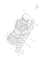
figure 1 is a perspective, diagrammatic view, with parts removed for clarity, of a mechanical gearbox which does not form part of the present invention; -
figure 2 is a perspective, diagrammatic view, with further parts removed for clarity, of the mechanical gearbox infigure 1 ; -
figure 3 is a diagrammatic, plan view, with further parts removed for clarity, of the mechanical gearbox infigure 1 ; -
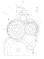
figure 4 is a side, diagrammatic view, with further parts removed for clarity, of the mechanical gearbox infigure 1 ; -
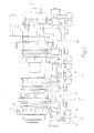
figure 5 is a plan, diagrammatic view, with parts removed for clarity, of a different embodiment of the mechanical gearbox infigure 1 which does not form part of the present invention; and -
figure 6 is a plan, diagrammatic view, with parts removed for clarity, of a variant of the mechanical gearbox infigure 5 made according to the present invention. - In
figure 1 , numeral 1 indicates as a whole a mechanical gearbox 1 for a vehicle adapted to receive motion from a thermal engine (not shown) of the vehicle by means of a propeller shaft 2 (shown infigure 4 ), which is mechanically connected to an engine shaft of the thermal engine by means of a clutch (not shown). Furthermore, the mechanical gearbox 1 is adapted to transmit the motion to the drive wheels (not shown) of the vehicle by means of adifferential 3 from which a pair of drive axles 4 depart, each of which is integral with a corresponding drive wheels. The mechanical gearbox 1 shown in the attached figures presents eight speeds in total : one reverse (indicated hereinafter by letter R) and seven forward gears from the first to the seventh (indicated hereinafter by Roman numerals I to VII). - As shown in
figure 2 , the mechanical gearbox 1 comprises a primary shaft 5 which receives the motion from the thermal engine and asecondary shaft 6 which transmits the motion to the drive wheels of the vehicle. The primary shaft 5 and thesecondary shaft 6 are reciprocally and mechanically coupled by means of a plurality of gear pairs, each of which defines a corresponding speed and a comprises a primary gear 7 (shown inFigure 4 ) coaxially mounted on the primary shaft 5 and a secondary gear 8 (shown inFigures 2 ,3 and4 ) coaxially mounted on thesecondary shaft 6. - In each gear pair which defines a corresponding speed, the primary gear 7 permanently meshes which the corresponding
secondary gear 8; furthermore, in each gear pair, agear 7 or 8 is rigidly mounted onto itsshaft 5 or 6, while theother gear 8 or 7 is idly mounted onto itsshaft 6 or 5 and coupled to asynchronizer 9 adapted to be actuated to engage theother gear 8 or 7 itself to itsshaft 6 or 5 (i.e. to make thegear 8 or 7 integral with theshaft 6 or 5). Consequently, a plurality ofsynchronizers 9 are contemplated, each of which is arranged coaxially to acorresponding shaft 6 or 5 between twogears 8 or 7 and is adapted to be actuated in order to alternatively engage the twogears 8 or 7 to thecorresponding shaft 6 or 5 (i.e, to make thegears 8 or 7 angular integral with theshaft 6 or 5). In other words, eachsynchronizer 9 may be displaced either in one sense to engage agear 8 or 7 onto thecorresponding shaft 6 or 5, or may be displaced in the other sense to engage theother gear 8 or 7 onto theshaft 6 or 5. - It is worth noting that the
synchronizers 9 either may all be mounted coaxially to the primary shaft 5 (i.e. all the primary gears 7 are idly mounted on the primary shaft 5 and are alternatively engaged onto the primary shaft 5 by the synchronizers 9) , or may all be mounted coaxially to the secondary shaft 6 (i.e. all thesecondary gears 8 are idly mounted on thesecondary shaft 6 and are alternatively engaged onto thesecondary shaft 6 by the synchronizers 9), or may be mounted coaxially either to the primary shaft 5 or to the secondary shaft 6 (i.e. some primary gears 7 are idly mounted on the primary shaft 5 and somesecondary gears 8 are idly mounted on the secondary shaft 6). - The mechanical gearbox 1 comprises an
actuation system 10, which is adapted to displace eachsynchronizer 9 alternatively in the two senses along thecorresponding shaft 6 or 5. Theactuation system 10 comprises a plurality offorks 11, each of which envelops acorresponding synchronizer 9 in order to push thesynchronizer 9 itself in the two directions along thecorresponding shaft 6 or 5. - As shown in
figure 2-4 , theactuation system 10 comprises arod 12 parallel to and by the side of thesecondary shaft 6 and supporting theforks 11, each of which presents aeyelet 13 slidingly fitted along therod 12. Furthermore, theactuation system 10 comprises for eachfork 11 anelectric actuator 14 adapted to displace thefork 11 along therod 12. In the embodiment shown in the accompanying figures, eachelectric actuator 14 comprises a pair ofsolenoids 15 each of which displaces thefork 11 in a corresponding direction. In a different embodiment (not shown), eachelectric actuator 14 comprises asingle solenoid 15 which is adapted to produce a displacement in a single direction and a further common solenoid is contemplated which varies the sense of application of such a displacement to theforks 11; in other words, the common solenoid determines the direction of the displacement of theforks 11. - In the mechanical gearbox 1, the gear pairs of two consecutive speeds are arranged so as to be engaged by two
different synchronizers 9; in other words, the gear pairs of two consecutive speeds (e.g. I and II, II and III, III and IV, or IV and V, etc.) are actuated by twodifferent synchronizers 9. For example, the following gear pair combinations may be contemplated in which the gear pairs are engaged by a same synchronizer 9: R and II, I and III, V and VII, IV and VI. - During a gear shift from a current speed to a subsequent speed consecutive to the current speed, the
actuation system 10 actuates, in reciprocally independent manner, thesynchronizers 9 of thegear 8 or 7 of the current speed and of thegear 8 or 7 of the subsequent speed; in this manner, during a gear shift from a current speed to a subsequent speed consecutive to the current speed, the actuation system actuates thesynchronizer 9 of thegear 8 or 7 of the current speed to disengage thegear 8 or 7 of the current speed itself from theshaft 6 or 5 and contemporarily actuates thesynchronizer 9 of thegear 8 or 7 of the subsequent speed to engage thegear 8 or 7 of the subsequent speed itself onto theshaft 6 or 5. - In other words, while the
synchronizer 9 of thegear 8 or 7 of the current speed is actuated to disengage thegear 8 or 7 of the current speed itself from theshaft 6 or 5, thesynchronizer 9 of thegear 8 or 7 of the subsequent speed is actuated to engage thegear 8 or 7 of the subsequent speed itself onto theshaft 6 or 5; in this manner, the current speed disengagement operation (i.e. disengagement of thegear 8 or 7 of the current speed from theshaft 6 or 5) and subsequent speed engagement operation (i.e. engagement of thegear 8 or 7 of the subsequent speed onto theshaft 6 or 5) are contemporarily performed with a evident reduction of the total gear shift operation time. The contemporaneousness of the current speed disengagement operation and of the subsequent speed engagement operation may be adjusted (i.e. increased or decreased) with appropriate advances or delays in order to reduce the gear shift times in favor of sportiness and to the detriment of comfort, or vice versa. In other words, for an extremely fast (thus very sporty and potentially not very comfortable) gear shift, the current speed disengagement operation and of the subsequent speed engagement operation may be completely contemporary; in this situation, it may occur that for a certain period of time (normally very short) both the gears are engaged with consequent scraping to the detriment of comfort (the scraping is very noisy and may cause longitudinal vibrations on the vehicles). Instead, for a slower (thus less sportier but more comfortable) gear shift, the contemporaneousness of the current speed disengagement operation and of the subsequent speed engagement operation may be reduced (i.e. the engagement of the subsequent speed is delayed with respect to the disengagement of the current speed); in this situation, it is very likely that for a period range of time (normally short) both the gears are disengaged. - The contemporaneousness of the current speed disengagement operation and of the subsequent speed engagement operation is made possible by the fact that the gear pairs of two consecutive speeds are arranged so as to be engaged by two
different synchronizers 9 and that theactuation system 10 allows to actuate thesynchronizers 9 in reciprocally independent manner. - According to the embodiment shown in
figure 5 , theactuation system 10 does not contemplate therod 12 nor theelectric actuators 14, but comprises ashaft 16 parallel to and by the side of the primary shaft 5 and thesecondary shaft 6 and supporting theforks 11, each of which presents aneyelet 17 slidingly fitted along theshaft 16. Theshaft 16 turns about acentral rotation axis 18 under the bias of amotor device 19 which may comprise an electronically controlled electric motor or may comprise a mechanical transmission which receives motion from a lever manually moved by a driver. A plurality ofcircumferential cams 21 are obtained on theexternal surface 20 of theshaft 16, each of which is associated to acorresponding fork 11. Furthermore, eachfork 11 is provided with afollower 22 which is integral with aneyelet 17 of thefork 11 and is inserted inside thecam 21 associated to thefork 11. - The rotation of the
shaft 16 about therotation shaft 18 determines an axial displacement of theforks 11 along therotation axis 18 depending on the shape of thecams 21 and on the type of coupling between thefollower 22 integral with the forks and thecams 21 themselves. Thecams 21 are shaped so that a series of determined angular positions are defined along the round angle, at each of which a corresponding speed is engaged; furthermore, thecams 21 are shaped so that when passing from one determined angular position (i.e. from a current gear) to another determined angular position (i.e. to the subsequent gear) the current gear and the subsequent gear are respectively disengaged and engaged at the same time as shown above. - According to a variant shown in
figure 6 , theshaft 16 is divided into twohalves elastic connection element 23 and each of which supports a part of theforks 11. - The above-described mechanical gearbox 1 presents many advantages, because it is simple and cost-effective to make and above all allows to shift very quickly between two consecutive speeds.
Claims (2)
- A mechanical gearbox (1) for a motor vehicle; the gearbox (1) comprises:a first shaft (5) ;a second shaft (6);a plurality of gear pairs, each of which mechanically couples the first shaft (5) to the second shaft (6), defines a corresponding speed and comprises a first gear (7) mounted on the first shaft (5) and a second gear (8) which is mounted on the second shaft (6) and permanently meshes with the first gear (7);a plurality of synchronizers (9), each of which is mounted coaxially to a shaft (6; 5) between two gears (8; 7) of two gear pairs and is adapted to be actuated to alternatively engage the two gears (8; 7) to the shaft (6; 5); andan actuation system (10) for displacing each synchronizer (9) alternatively in the two senses along the respective shaft (6; 5) and comprising a plurality of forks (11), each of which envelops a respective synchronizer (9) ;wherein gear pairs of two consecutive speeds are arranged so as to be engaged by two different synchronizers (9); andwherein the actuation system (10) independently actuates the synchronizers (9);the gearbox (1) is characterized in that the actuation system (10) comprises:a third shaft (16) parallel to and by the side of the first and second shaft (5, 6) and supporting the forks (11), each of which presents an eyelet (17) slidingly fitted along the third shaft (16);a plurality of circumferential cams (21), each of which is obtained on the external surface (20) of the third shaft (16) and is associated to a corresponding fork (11);a plurality of followers (22), each of which is integral with the eyelet (17) of a fork (11) and is inserted in the cam (21) associated to the fork (11) thereof; anda motor device (19), which is adapted to turn the third shaft (16) about a central rotation axis (18) thereof;wherein the third shaft (16) is split into two halves (16a, 16b), which are connected together by means of an elastic element (23) and each of which supports a part of the forks (11).
- A gearbox (1) according to claim 1, wherein the motor device (19) is electric.
Applications Claiming Priority (2)
| Application Number | Priority Date | Filing Date | Title |
|---|---|---|---|
| IT000473A ITBO20070473A1 (en) | 2007-07-11 | 2007-07-11 | MECHANICAL CHANGE FOR AUTOMOTIVE |
| EP08788875A EP2171309B1 (en) | 2007-07-11 | 2008-07-10 | Mechanical gearbox for motor vehicles |
Related Parent Applications (2)
| Application Number | Title | Priority Date | Filing Date |
|---|---|---|---|
| EP08788875.6 Division | 2008-07-10 | ||
| EP08788875A Division EP2171309B1 (en) | 2007-07-11 | 2008-07-10 | Mechanical gearbox for motor vehicles |
Publications (3)
| Publication Number | Publication Date |
|---|---|
| EP2302259A2 true EP2302259A2 (en) | 2011-03-30 |
| EP2302259A3 EP2302259A3 (en) | 2011-05-25 |
| EP2302259B1 EP2302259B1 (en) | 2012-09-12 |
Family
ID=40090398
Family Applications (2)
| Application Number | Title | Priority Date | Filing Date |
|---|---|---|---|
| EP08788875A Active EP2171309B1 (en) | 2007-07-11 | 2008-07-10 | Mechanical gearbox for motor vehicles |
| EP11151054A Active EP2302259B1 (en) | 2007-07-11 | 2008-07-10 | Mechanical gearbox for motor vehicles |
Family Applications Before (1)
| Application Number | Title | Priority Date | Filing Date |
|---|---|---|---|
| EP08788875A Active EP2171309B1 (en) | 2007-07-11 | 2008-07-10 | Mechanical gearbox for motor vehicles |
Country Status (5)
| Country | Link |
|---|---|
| US (1) | US8677846B2 (en) |
| EP (2) | EP2171309B1 (en) |
| AT (1) | ATE544973T1 (en) |
| IT (1) | ITBO20070473A1 (en) |
| WO (1) | WO2009007833A2 (en) |
Families Citing this family (1)
| Publication number | Priority date | Publication date | Assignee | Title |
|---|---|---|---|---|
| ITBO20070473A1 (en) * | 2007-07-11 | 2009-01-12 | Ferrari Spa | MECHANICAL CHANGE FOR AUTOMOTIVE |
Citations (2)
| Publication number | Priority date | Publication date | Assignee | Title |
|---|---|---|---|---|
| JPH0419462A (en) | 1990-05-11 | 1992-01-23 | Honda Motor Co Ltd | Electronically controlled transmission |
| US20040192499A1 (en) | 2003-03-28 | 2004-09-30 | Hitachi, Ltd. | Car control apparatus and control method |
Family Cites Families (19)
| Publication number | Priority date | Publication date | Assignee | Title |
|---|---|---|---|---|
| US2857772A (en) * | 1954-07-01 | 1958-10-28 | Rech S Pour Engins Mecaniques | Change speed gearings |
| JPS5894657A (en) * | 1981-12-01 | 1983-06-04 | Toyota Motor Corp | Gear type speed changing device |
| US4833933A (en) * | 1987-06-22 | 1989-05-30 | Ford New Holland, Inc. | Alternate path tractor transmission having a redundant clutch |
| WO1989006194A1 (en) * | 1988-01-07 | 1989-07-13 | Moskovsky Avtomobilny Zavod Imeni I.A.Likhacheva ( | Device for controlling a multi-component transmission of a vehicle |
| US5105902A (en) * | 1990-12-07 | 1992-04-21 | New Venture Gear, Inc. | Transfer case shift-on-fly system |
| GB2315470A (en) * | 1996-07-20 | 1998-02-04 | Ford New Holland Nv | Gear selection system for a harvester |
| US5888165A (en) * | 1997-05-09 | 1999-03-30 | Ford Global Technologies, Inc. | Multiple-speed axle mechanism |
| JP2002526326A (en) * | 1998-10-02 | 2002-08-20 | ルーク ラメレン ウント クツプルングスバウ ベタイリグングス コマンディートゲゼルシャフト | Transmission having at least two shafts and an electric machine or automatic disc clutch |
| DE19908602A1 (en) * | 1999-02-27 | 2000-09-14 | Getrag Getriebe Zahnrad | Automated drive train for a motor vehicle and method for controlling a drive train |
| ES2222161T3 (en) | 1999-07-22 | 2005-02-01 | Peugeot Citroen Automobiles Sa | DRUM SELECTOR OF SPEEDS FOR MULTIPLE RELATIONSHIP GEARBOX FOR MOTOR VEHICLES. |
| JP2001213201A (en) * | 1999-12-17 | 2001-08-07 | Getrag Getriebe & Zahnradfab Hermann Hagenmeyer Gmbh & Co | Automatic drive train for automobiles and method of controlling drive train |
| DE10011271B4 (en) * | 2000-03-08 | 2009-04-09 | Daimler Ag | Multi-step transmission with a selector and selector |
| FR2810713B1 (en) | 2000-06-23 | 2002-10-31 | Renault | METHOD AND MECHANISM FOR CHANGING SPEEDS UNDER TORQUE |
| EP1544513B1 (en) * | 2001-01-12 | 2009-02-18 | ZF Sachs AG | Vehicle with a drivetrain having a multiple clutch device |
| KR20030080031A (en) * | 2001-02-23 | 2003-10-10 | 루크 라멜렌 운트 쿠플룽스바우 베타일리궁스 카게 | Transmission |
| DE10136232A1 (en) * | 2001-07-25 | 2003-02-06 | Zahnradfabrik Friedrichshafen | Actuating device for an automated multi-step transmission of a motor vehicle |
| DE10340149B4 (en) * | 2003-08-26 | 2007-08-16 | Getrag Getriebe- Und Zahnradfabrik Hermann Hagenmeyer Gmbh & Cie Kg | Camshaft actuated motor vehicle gearbox |
| GB0510129D0 (en) * | 2005-05-18 | 2005-06-22 | Zeroshift Ltd | Sequential hub layout |
| ITBO20070473A1 (en) * | 2007-07-11 | 2009-01-12 | Ferrari Spa | MECHANICAL CHANGE FOR AUTOMOTIVE |
-
2007
- 2007-07-11 IT IT000473A patent/ITBO20070473A1/en unknown
-
2008
- 2008-07-10 US US12/668,620 patent/US8677846B2/en active Active
- 2008-07-10 WO PCT/IB2008/001805 patent/WO2009007833A2/en not_active Ceased
- 2008-07-10 EP EP08788875A patent/EP2171309B1/en active Active
- 2008-07-10 AT AT08788875T patent/ATE544973T1/en active
- 2008-07-10 EP EP11151054A patent/EP2302259B1/en active Active
Patent Citations (2)
| Publication number | Priority date | Publication date | Assignee | Title |
|---|---|---|---|---|
| JPH0419462A (en) | 1990-05-11 | 1992-01-23 | Honda Motor Co Ltd | Electronically controlled transmission |
| US20040192499A1 (en) | 2003-03-28 | 2004-09-30 | Hitachi, Ltd. | Car control apparatus and control method |
Also Published As
| Publication number | Publication date |
|---|---|
| ITBO20070473A1 (en) | 2009-01-12 |
| US20100257968A1 (en) | 2010-10-14 |
| WO2009007833A2 (en) | 2009-01-15 |
| WO2009007833A3 (en) | 2009-05-22 |
| ATE544973T1 (en) | 2012-02-15 |
| EP2171309A2 (en) | 2010-04-07 |
| EP2302259A3 (en) | 2011-05-25 |
| EP2171309B1 (en) | 2012-02-08 |
| US8677846B2 (en) | 2014-03-25 |
| EP2302259B1 (en) | 2012-09-12 |
Similar Documents
| Publication | Publication Date | Title |
|---|---|---|
| US7661331B2 (en) | Shifting device for dual clutch transmission | |
| US9279497B2 (en) | Connecting device for outside a variable-speed transmission | |
| EP2407688B1 (en) | Twin clutch transmission for large-sized vehicle | |
| CN101446320B (en) | Vehicle shift control apparatus | |
| EP3120045B1 (en) | Heavy duty transmission architecture | |
| EP0691486B1 (en) | A twin-clutch-type transmission | |
| US9103440B2 (en) | Motor vehicle drive train device comprising a multi-group transmission and shifting method for a multi-group transmission | |
| US8915160B2 (en) | Group transmission device | |
| RU2395738C2 (en) | Gearshift control system in automatic transmission | |
| EP2143979B1 (en) | Double-clutch gearchange | |
| US20150027254A1 (en) | Motor Vehicle Drive Train Device Comprising a Multi-Group Transmission | |
| EP2171309B1 (en) | Mechanical gearbox for motor vehicles | |
| US8794089B2 (en) | Transmission | |
| EP2372199B1 (en) | Automatic manual transmission provided with parking lock device | |
| US20020014131A1 (en) | Transmission | |
| EP2019230A1 (en) | Servo-assisted mechanical gearbox with hydraulic actuation of the synchronizers | |
| US11460107B2 (en) | Selector drum and motor-vehicle manual transmission | |
| JP5658069B2 (en) | Transmission | |
| EP1916446B1 (en) | Gearbox with synchronising clutch | |
| EP4474680A1 (en) | Transmission | |
| JP2003161347A (en) | Transmission for vehicles | |
| WO2011013043A1 (en) | A gearbox for motor vehicles | |
| JP2003336734A (en) | Control device and control method for automatic transmission | |
| EP2116745A1 (en) | Electric servo-control for a servo-assited gearbox | |
| IL174408A (en) | Motor vehicle gearbox |
Legal Events
| Date | Code | Title | Description |
|---|---|---|---|
| PUAI | Public reference made under article 153(3) epc to a published international application that has entered the european phase |
Free format text: ORIGINAL CODE: 0009012 |
|
| AC | Divisional application: reference to earlier application |
Ref document number: 2171309 Country of ref document: EP Kind code of ref document: P |
|
| AK | Designated contracting states |
Kind code of ref document: A2 Designated state(s): AT BE BG CH CY CZ DE DK EE ES FI FR GB GR HR HU IE IS IT LI LT LU LV MC MT NL NO PL PT RO SE SI SK TR |
|
| PUAL | Search report despatched |
Free format text: ORIGINAL CODE: 0009013 |
|
| AK | Designated contracting states |
Kind code of ref document: A3 Designated state(s): AT BE BG CH CY CZ DE DK EE ES FI FR GB GR HR HU IE IS IT LI LT LU LV MC MT NL NO PL PT RO SE SI SK TR |
|
| RIC1 | Information provided on ipc code assigned before grant |
Ipc: F16H 3/089 20060101AFI20110216BHEP Ipc: F16H 63/18 20060101ALI20110418BHEP |
|
| 17P | Request for examination filed |
Effective date: 20111124 |
|
| GRAP | Despatch of communication of intention to grant a patent |
Free format text: ORIGINAL CODE: EPIDOSNIGR1 |
|
| GRAS | Grant fee paid |
Free format text: ORIGINAL CODE: EPIDOSNIGR3 |
|
| GRAA | (expected) grant |
Free format text: ORIGINAL CODE: 0009210 |
|
| AC | Divisional application: reference to earlier application |
Ref document number: 2171309 Country of ref document: EP Kind code of ref document: P |
|
| AK | Designated contracting states |
Kind code of ref document: B1 Designated state(s): AT BE BG CH CY CZ DE DK EE ES FI FR GB GR HR HU IE IS IT LI LT LU LV MC MT NL NO PL PT RO SE SI SK TR |
|
| REG | Reference to a national code |
Ref country code: GB Ref legal event code: FG4D |
|
| REG | Reference to a national code |
Ref country code: CH Ref legal event code: EP |
|
| REG | Reference to a national code |
Ref country code: AT Ref legal event code: REF Ref document number: 575250 Country of ref document: AT Kind code of ref document: T Effective date: 20120915 |
|
| REG | Reference to a national code |
Ref country code: IE Ref legal event code: FG4D |
|
| REG | Reference to a national code |
Ref country code: DE Ref legal event code: R096 Ref document number: 602008018814 Country of ref document: DE Effective date: 20121108 |
|
| PG25 | Lapsed in a contracting state [announced via postgrant information from national office to epo] |
Ref country code: NO Free format text: LAPSE BECAUSE OF FAILURE TO SUBMIT A TRANSLATION OF THE DESCRIPTION OR TO PAY THE FEE WITHIN THE PRESCRIBED TIME-LIMIT Effective date: 20121212 Ref country code: LT Free format text: LAPSE BECAUSE OF FAILURE TO SUBMIT A TRANSLATION OF THE DESCRIPTION OR TO PAY THE FEE WITHIN THE PRESCRIBED TIME-LIMIT Effective date: 20120912 Ref country code: FI Free format text: LAPSE BECAUSE OF FAILURE TO SUBMIT A TRANSLATION OF THE DESCRIPTION OR TO PAY THE FEE WITHIN THE PRESCRIBED TIME-LIMIT Effective date: 20120912 Ref country code: HR Free format text: LAPSE BECAUSE OF FAILURE TO SUBMIT A TRANSLATION OF THE DESCRIPTION OR TO PAY THE FEE WITHIN THE PRESCRIBED TIME-LIMIT Effective date: 20120912 |
|
| REG | Reference to a national code |
Ref country code: NL Ref legal event code: VDEP Effective date: 20120912 |
|
| REG | Reference to a national code |
Ref country code: AT Ref legal event code: MK05 Ref document number: 575250 Country of ref document: AT Kind code of ref document: T Effective date: 20120912 |
|
| REG | Reference to a national code |
Ref country code: LT Ref legal event code: MG4D Effective date: 20120912 |
|
| PG25 | Lapsed in a contracting state [announced via postgrant information from national office to epo] |
Ref country code: SE Free format text: LAPSE BECAUSE OF FAILURE TO SUBMIT A TRANSLATION OF THE DESCRIPTION OR TO PAY THE FEE WITHIN THE PRESCRIBED TIME-LIMIT Effective date: 20120912 Ref country code: GR Free format text: LAPSE BECAUSE OF FAILURE TO SUBMIT A TRANSLATION OF THE DESCRIPTION OR TO PAY THE FEE WITHIN THE PRESCRIBED TIME-LIMIT Effective date: 20121213 Ref country code: SI Free format text: LAPSE BECAUSE OF FAILURE TO SUBMIT A TRANSLATION OF THE DESCRIPTION OR TO PAY THE FEE WITHIN THE PRESCRIBED TIME-LIMIT Effective date: 20120912 Ref country code: LV Free format text: LAPSE BECAUSE OF FAILURE TO SUBMIT A TRANSLATION OF THE DESCRIPTION OR TO PAY THE FEE WITHIN THE PRESCRIBED TIME-LIMIT Effective date: 20120912 |
|
| PG25 | Lapsed in a contracting state [announced via postgrant information from national office to epo] |
Ref country code: BE Free format text: LAPSE BECAUSE OF FAILURE TO SUBMIT A TRANSLATION OF THE DESCRIPTION OR TO PAY THE FEE WITHIN THE PRESCRIBED TIME-LIMIT Effective date: 20120912 Ref country code: EE Free format text: LAPSE BECAUSE OF FAILURE TO SUBMIT A TRANSLATION OF THE DESCRIPTION OR TO PAY THE FEE WITHIN THE PRESCRIBED TIME-LIMIT Effective date: 20120912 Ref country code: CZ Free format text: LAPSE BECAUSE OF FAILURE TO SUBMIT A TRANSLATION OF THE DESCRIPTION OR TO PAY THE FEE WITHIN THE PRESCRIBED TIME-LIMIT Effective date: 20120912 Ref country code: RO Free format text: LAPSE BECAUSE OF FAILURE TO SUBMIT A TRANSLATION OF THE DESCRIPTION OR TO PAY THE FEE WITHIN THE PRESCRIBED TIME-LIMIT Effective date: 20120912 Ref country code: NL Free format text: LAPSE BECAUSE OF FAILURE TO SUBMIT A TRANSLATION OF THE DESCRIPTION OR TO PAY THE FEE WITHIN THE PRESCRIBED TIME-LIMIT Effective date: 20120912 Ref country code: IS Free format text: LAPSE BECAUSE OF FAILURE TO SUBMIT A TRANSLATION OF THE DESCRIPTION OR TO PAY THE FEE WITHIN THE PRESCRIBED TIME-LIMIT Effective date: 20130112 Ref country code: ES Free format text: LAPSE BECAUSE OF FAILURE TO SUBMIT A TRANSLATION OF THE DESCRIPTION OR TO PAY THE FEE WITHIN THE PRESCRIBED TIME-LIMIT Effective date: 20121223 |
|
| PG25 | Lapsed in a contracting state [announced via postgrant information from national office to epo] |
Ref country code: SK Free format text: LAPSE BECAUSE OF FAILURE TO SUBMIT A TRANSLATION OF THE DESCRIPTION OR TO PAY THE FEE WITHIN THE PRESCRIBED TIME-LIMIT Effective date: 20120912 Ref country code: PT Free format text: LAPSE BECAUSE OF FAILURE TO SUBMIT A TRANSLATION OF THE DESCRIPTION OR TO PAY THE FEE WITHIN THE PRESCRIBED TIME-LIMIT Effective date: 20130114 Ref country code: PL Free format text: LAPSE BECAUSE OF FAILURE TO SUBMIT A TRANSLATION OF THE DESCRIPTION OR TO PAY THE FEE WITHIN THE PRESCRIBED TIME-LIMIT Effective date: 20120912 |
|
| PG25 | Lapsed in a contracting state [announced via postgrant information from national office to epo] |
Ref country code: AT Free format text: LAPSE BECAUSE OF FAILURE TO SUBMIT A TRANSLATION OF THE DESCRIPTION OR TO PAY THE FEE WITHIN THE PRESCRIBED TIME-LIMIT Effective date: 20120912 |
|
| PLBE | No opposition filed within time limit |
Free format text: ORIGINAL CODE: 0009261 |
|
| STAA | Information on the status of an ep patent application or granted ep patent |
Free format text: STATUS: NO OPPOSITION FILED WITHIN TIME LIMIT |
|
| PG25 | Lapsed in a contracting state [announced via postgrant information from national office to epo] |
Ref country code: DK Free format text: LAPSE BECAUSE OF FAILURE TO SUBMIT A TRANSLATION OF THE DESCRIPTION OR TO PAY THE FEE WITHIN THE PRESCRIBED TIME-LIMIT Effective date: 20120912 Ref country code: BG Free format text: LAPSE BECAUSE OF FAILURE TO SUBMIT A TRANSLATION OF THE DESCRIPTION OR TO PAY THE FEE WITHIN THE PRESCRIBED TIME-LIMIT Effective date: 20121212 |
|
| 26N | No opposition filed |
Effective date: 20130613 |
|
| PG25 | Lapsed in a contracting state [announced via postgrant information from national office to epo] |
Ref country code: IT Free format text: LAPSE BECAUSE OF FAILURE TO SUBMIT A TRANSLATION OF THE DESCRIPTION OR TO PAY THE FEE WITHIN THE PRESCRIBED TIME-LIMIT Effective date: 20120912 |
|
| REG | Reference to a national code |
Ref country code: DE Ref legal event code: R097 Ref document number: 602008018814 Country of ref document: DE Effective date: 20130613 |
|
| PG25 | Lapsed in a contracting state [announced via postgrant information from national office to epo] |
Ref country code: CY Free format text: LAPSE BECAUSE OF FAILURE TO SUBMIT A TRANSLATION OF THE DESCRIPTION OR TO PAY THE FEE WITHIN THE PRESCRIBED TIME-LIMIT Effective date: 20120912 |
|
| PG25 | Lapsed in a contracting state [announced via postgrant information from national office to epo] |
Ref country code: MC Free format text: LAPSE BECAUSE OF FAILURE TO SUBMIT A TRANSLATION OF THE DESCRIPTION OR TO PAY THE FEE WITHIN THE PRESCRIBED TIME-LIMIT Effective date: 20120912 |
|
| REG | Reference to a national code |
Ref country code: CH Ref legal event code: PL |
|
| REG | Reference to a national code |
Ref country code: IE Ref legal event code: MM4A |
|
| REG | Reference to a national code |
Ref country code: FR Ref legal event code: ST Effective date: 20140331 |
|
| PG25 | Lapsed in a contracting state [announced via postgrant information from national office to epo] |
Ref country code: CH Free format text: LAPSE BECAUSE OF NON-PAYMENT OF DUE FEES Effective date: 20130731 Ref country code: LI Free format text: LAPSE BECAUSE OF NON-PAYMENT OF DUE FEES Effective date: 20130731 |
|
| PG25 | Lapsed in a contracting state [announced via postgrant information from national office to epo] |
Ref country code: FR Free format text: LAPSE BECAUSE OF NON-PAYMENT OF DUE FEES Effective date: 20130731 |
|
| PG25 | Lapsed in a contracting state [announced via postgrant information from national office to epo] |
Ref country code: IE Free format text: LAPSE BECAUSE OF NON-PAYMENT OF DUE FEES Effective date: 20130710 |
|
| PG25 | Lapsed in a contracting state [announced via postgrant information from national office to epo] |
Ref country code: MT Free format text: LAPSE BECAUSE OF FAILURE TO SUBMIT A TRANSLATION OF THE DESCRIPTION OR TO PAY THE FEE WITHIN THE PRESCRIBED TIME-LIMIT Effective date: 20120912 Ref country code: TR Free format text: LAPSE BECAUSE OF FAILURE TO SUBMIT A TRANSLATION OF THE DESCRIPTION OR TO PAY THE FEE WITHIN THE PRESCRIBED TIME-LIMIT Effective date: 20120912 |
|
| PG25 | Lapsed in a contracting state [announced via postgrant information from national office to epo] |
Ref country code: LU Free format text: LAPSE BECAUSE OF NON-PAYMENT OF DUE FEES Effective date: 20130710 Ref country code: HU Free format text: LAPSE BECAUSE OF FAILURE TO SUBMIT A TRANSLATION OF THE DESCRIPTION OR TO PAY THE FEE WITHIN THE PRESCRIBED TIME-LIMIT; INVALID AB INITIO Effective date: 20080710 |
|
| P01 | Opt-out of the competence of the unified patent court (upc) registered |
Effective date: 20230525 |
|
| PGFP | Annual fee paid to national office [announced via postgrant information from national office to epo] |
Ref country code: DE Payment date: 20250728 Year of fee payment: 18 |
|
| PGFP | Annual fee paid to national office [announced via postgrant information from national office to epo] |
Ref country code: GB Payment date: 20250722 Year of fee payment: 18 |