EP2302202A1 - Hydraulic propulsion for increases of hydroelektric power station capacity - Google Patents
Hydraulic propulsion for increases of hydroelektric power station capacity Download PDFInfo
- Publication number
- EP2302202A1 EP2302202A1 EP09466021A EP09466021A EP2302202A1 EP 2302202 A1 EP2302202 A1 EP 2302202A1 EP 09466021 A EP09466021 A EP 09466021A EP 09466021 A EP09466021 A EP 09466021A EP 2302202 A1 EP2302202 A1 EP 2302202A1
- Authority
- EP
- European Patent Office
- Prior art keywords
- tank
- water
- hydraulic propulsion
- power station
- piston
- Prior art date
- Legal status (The legal status is an assumption and is not a legal conclusion. Google has not performed a legal analysis and makes no representation as to the accuracy of the status listed.)
- Granted
Links
- XLYOFNOQVPJJNP-UHFFFAOYSA-N water Substances O XLYOFNOQVPJJNP-UHFFFAOYSA-N 0.000 claims abstract description 103
- 238000010276 construction Methods 0.000 claims description 14
- 230000005611 electricity Effects 0.000 abstract description 5
- 238000004519 manufacturing process Methods 0.000 abstract description 5
- 230000008520 organization Effects 0.000 description 19
- 230000004075 alteration Effects 0.000 description 12
- 238000009434 installation Methods 0.000 description 2
- 241000842962 Apoda limacodes Species 0.000 description 1
- 230000001133 acceleration Effects 0.000 description 1
- 230000001427 coherent effect Effects 0.000 description 1
- 238000010586 diagram Methods 0.000 description 1
- 230000000694 effects Effects 0.000 description 1
- 238000005516 engineering process Methods 0.000 description 1
Images


Classifications
-
- F—MECHANICAL ENGINEERING; LIGHTING; HEATING; WEAPONS; BLASTING
- F03—MACHINES OR ENGINES FOR LIQUIDS; WIND, SPRING, OR WEIGHT MOTORS; PRODUCING MECHANICAL POWER OR A REACTIVE PROPULSIVE THRUST, NOT OTHERWISE PROVIDED FOR
- F03B—MACHINES OR ENGINES FOR LIQUIDS
- F03B13/00—Adaptations of machines or engines for special use; Combinations of machines or engines with driving or driven apparatus; Power stations or aggregates
- F03B13/06—Stations or aggregates of water-storage type, e.g. comprising a turbine and a pump
-
- F—MECHANICAL ENGINEERING; LIGHTING; HEATING; WEAPONS; BLASTING
- F03—MACHINES OR ENGINES FOR LIQUIDS; WIND, SPRING, OR WEIGHT MOTORS; PRODUCING MECHANICAL POWER OR A REACTIVE PROPULSIVE THRUST, NOT OTHERWISE PROVIDED FOR
- F03B—MACHINES OR ENGINES FOR LIQUIDS
- F03B13/00—Adaptations of machines or engines for special use; Combinations of machines or engines with driving or driven apparatus; Power stations or aggregates
-
- Y—GENERAL TAGGING OF NEW TECHNOLOGICAL DEVELOPMENTS; GENERAL TAGGING OF CROSS-SECTIONAL TECHNOLOGIES SPANNING OVER SEVERAL SECTIONS OF THE IPC; TECHNICAL SUBJECTS COVERED BY FORMER USPC CROSS-REFERENCE ART COLLECTIONS [XRACs] AND DIGESTS
- Y02—TECHNOLOGIES OR APPLICATIONS FOR MITIGATION OR ADAPTATION AGAINST CLIMATE CHANGE
- Y02E—REDUCTION OF GREENHOUSE GAS [GHG] EMISSIONS, RELATED TO ENERGY GENERATION, TRANSMISSION OR DISTRIBUTION
- Y02E10/00—Energy generation through renewable energy sources
- Y02E10/20—Hydro energy
-
- Y—GENERAL TAGGING OF NEW TECHNOLOGICAL DEVELOPMENTS; GENERAL TAGGING OF CROSS-SECTIONAL TECHNOLOGIES SPANNING OVER SEVERAL SECTIONS OF THE IPC; TECHNICAL SUBJECTS COVERED BY FORMER USPC CROSS-REFERENCE ART COLLECTIONS [XRACs] AND DIGESTS
- Y02—TECHNOLOGIES OR APPLICATIONS FOR MITIGATION OR ADAPTATION AGAINST CLIMATE CHANGE
- Y02E—REDUCTION OF GREENHOUSE GAS [GHG] EMISSIONS, RELATED TO ENERGY GENERATION, TRANSMISSION OR DISTRIBUTION
- Y02E60/00—Enabling technologies; Technologies with a potential or indirect contribution to GHG emissions mitigation
- Y02E60/16—Mechanical energy storage, e.g. flywheels or pressurised fluids
-
- Y—GENERAL TAGGING OF NEW TECHNOLOGICAL DEVELOPMENTS; GENERAL TAGGING OF CROSS-SECTIONAL TECHNOLOGIES SPANNING OVER SEVERAL SECTIONS OF THE IPC; TECHNICAL SUBJECTS COVERED BY FORMER USPC CROSS-REFERENCE ART COLLECTIONS [XRACs] AND DIGESTS
- Y02—TECHNOLOGIES OR APPLICATIONS FOR MITIGATION OR ADAPTATION AGAINST CLIMATE CHANGE
- Y02P—CLIMATE CHANGE MITIGATION TECHNOLOGIES IN THE PRODUCTION OR PROCESSING OF GOODS
- Y02P70/00—Climate change mitigation technologies in the production process for final industrial or consumer products
- Y02P70/50—Manufacturing or production processes characterised by the final manufactured product
Definitions
- Invention is concerned with a new plant serves for increases of Hydroelectric Power Station capacity while keeping the same usable head and flow of water. Supposed usage of this mechanism will be in Hydroelectric Power Stations, working on the principle of two interconnected tanks separated by a dam which causes difference in height of both water levels. Invention uses lifting and gravitation force which is by the force of Hydraulic Piston converted to compressive force increasing Hydroelectric Power Station capacity. An example of invention utilization can be Hydroelectric Power Station on a dam reservoir.
- the most significant plant of Hydroelectric Power Station is water turbine who converts hydraulic energy of flowing water to mechanical power (shaft rotation).
- One of the important parameters of water turbine is its mechanical power. That presents mechanical energy transferred by its shaft.
- Theoretical turbine power if we leave out its efficiency and other dissipations, depends on two basic parameters, flow rate Q and specific energy E, which is given by usable head H.
- Water turbine capacity is possible to increase by the flow of water through a turbine or by increasing of usable head, eventually through the combination of both of them.
- Hydroelectric Power Stations are usually built on rivers where they are embanked.
- Typical example can be Hydroelectric Power Station on a dam reservoir.
- usable head Difference in height of both water levels in front of and behind a dam.
- By increasing height of a dam (usable head) area around will be flooded counter a course of a river. Consequently, that means that one of the important parameter of Hydroelectric Power Station capacity is impossible to increase and it is determined by natural conditions and by a technical construction of hydroelectric installation (a dam reservoir).
- Another parameter determining the capacity of Hydroelectric Power Station is flow of water.
- This parameter is also in practice noncontrollable, because it is due to flow of river into a dam reservoir influent, respectively from a dam reservoir flowing out.
- the last parameter determines Hydroelectric Power Station capacity, which is possible to influence, is the water turbine efficiency. At present water turbines maintain efficiency at about 90%.
- Effort of this invention is to increase Hydroelectric Power Station capacity in a different way than just by increasing water turbine efficiency, whereas practically influenceable parameters, like a flow of water and a usable head, remain unchanged.
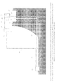
- figure 1 is constructed by two tanks 1 and 2 .
- the tank 1 is partly opened in that way so that it floats afloat a dam reservoir 41 and is permanently connected with a piston 8 which is closed in tank 2.
- Tank 1 is connected through pipes 13 and 12 with pipe 19 . Water from tank 1 is possible to desist through pipes 13 , 12 and 19 into Hydroelectric Power Station 43.
- Tank 2 is connected through pipes 20 and 21 with a compressed air tank 6 which is through pipe 48 joined on Hydroelectric Power Station 43.
- the whole Hydraulic propulsion is equipped with a closing valves system 29 , 30 , 31 , 32 , 33 , 34 , 40 , 46 and with a system of controllable one-way valves 35 and 36 .
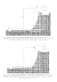
- Tank 1 is from 3 ⁇ 4 flooded with water from a dam reservoir 41 and it floats afloat, see figure 2 .
- the force keeping tank 1 afloat a dam reservoir 41 is given by an Archimedes principle. In case that the whole construction of the tank 1 would have no weight, the water level in tank 1 would be at the same level, like a water level in a dam reservoir 41. Whereas a tank construction 1 has a weight there will arise a level difference, which is determined by a weight of a tank construction 1 , see figure 2 .
- Tank 1 is tied so that it can move only vertically (up and down).
- Tank 2 is firmly fastened so that it cannot move.
- the Hydraulic propulsion works in two consecutive and still repeating cycles.
- tank 1 is flooded from 3 ⁇ 4 with water, see figure 2 .
- closing valves will be closed 29 , 30 , 31, 34 , 39 and closing valves will be opened 32 , 33 , 40 .
- a space of tank 2 above the piston 8 is totally closed and filled up with atmospheric air.
- Water from tank 1 is desisted to turbines in Hydroelectric Power Station 43 through pipes 13 , 12 and 19 . Desisting of water from tank 1 will cause, that lifting force will lift tank upwards.
- Level difference of tank 1 and dam reservoir 41 remain the same, it is due to the weight of a tank construction 1 .
- Tank 1 is firmly connected with the piston 8 placed in tank 2 whose subsequent motion causes a pressure alteration of a closed atmospheric air.
- closed closing valve 33 and controllable one-way valve 35 compressed air will get to compressed air tank 6, from which it is brought to Hydroelectric Power Station 43 through the controllable one-way valve 36, where through high-pressure turbines it helps water turbines to rotate electrical generators (high-pressure turbine can be installed on shaft common with the water turbine, which rotates a rotor of an electric generator).
- closing valves (primarily opened) will be closed 32, 33 and 40. At the same time, closing valves will be opened 29 , 30 , 31 , 34 and 39 .
- Closing valves which are opened 29 and 30 cause filling tank 1 with water from a dam reservoir 41 , which will sink down owing to its weight whereon gravitation force takes an effect.
- Closed atmospheric air in a lower part of tank 2 is compressed by the motion of a piston 8. The motion of a piston 8 causes pressure alteration of closed atmospheric air.
- compressed air will get into compressed air tank 6 where it is led in to Hydroelectric Power Station 43 , where through high pressure turbines it helps the water turbines to rotate electrical generators.
- the Hydraulic propulsion uses two new forces that they have not been used for electricity production up to now - a lifting force effecting tank 1 which cause its lifting in the first working cycle and a gravitation force effecting heavy tank construction 1 , causing its back falling by watering in the second working cycle.
- the Hydraulic propulsion is possible to modify so that it would be possible to use also without high pressure turbine.
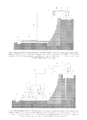
- FIG 6 By one of possible configuration, that does not use high pressure turbine, is presented on figure 6 .
- this configuration is the Hydraulic propulsion extended over a tank 3 which is equipped by a sliding piston 7 , divided a tank into two parts (left and right).
- At each part of tank 3 there are joined two pipes on the left side 15 , 18 and two pipes on the right side 14 , 17 .
- Pipes 14 and 15 are joined on pipe 12 which draws water from a dam reservoir 41 .
- Pipes 17 and 18 are joined on a pipe 19 which leads water into Hydroelectric Power Station 43 .
- a connecting rod 11 On a piston 7 is fastened a connecting rod 11 which goes through a tank 3 and it is constructed so that water from a tank 3 cannot run out to the surroundings, also in the event of its linear motion.
- pistons 9 and 10 On both sides of a connecting rod 11 are fastened pistons 9 and 10 which are closed in tanks 4 and 5 .
- Tanks 4 and 5 are connected through pipes 22 in compressed air tank 6 .
- the tank 1 is partly opened so that it floats afloat a dam reservoir 41 and is firmly connected with a piston 8 which is closed in a tank 2.
- Tank 1 is connected by a pipe 13 with a pipe 12 . Water from a tank 1 is possible to desist through a pipe 13 and other successive pipes 12 , 14 , 15 , 17 , 18 and 19 in Hydroelectric Power Station 43.
- a tank 2 is connected through pipes 20 a 21 with a festoon on a compressed air tank 6.
- the whole Hydraulic propulsion is equipped with the closing valves system 23 , 24 , 25 , 26 , 27 , 28 , 29 , 30 , 31 , 32 , 33 , 34 , 37 , 38 , 39 , 40 , 46 and with the system of controllable one-way valves 35 , 36 .
- the Hydraulic propulsion in this organization works again in two consecutive and still repeating cycles. Before starting the system, it is necessary to fill the whole system with water from a dam reservoir, through a pipe 16 , closing valve 40 is closed, so that the water from a dam cannot break into tank 1 .
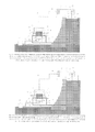
- tank is from 3 ⁇ 4 flooded with water, see figure 7 , piston 7 is situated on the right side of a tank 3 .
- closing valves are closed 23 , 25 , 27 , 29 , 30 , 31 , 32 , 34 , 37 and 39 .
- controllable one-way valves are opened 24 , 26 , 28 , 32 , 33, 35, 36 38 and 40.
- Hydrostatical pressure on the right side of a tank 3 is higher than hydrostatical pressure on the left side which are separated by a piston 7 from each other. The pressure on the right side of a tank 3 causes the piston motion 7 leftwards.
- the motion of a piston increases a capacity of a right side of a tank 3 which will cause desisting water from a tank 1.
- Tank 1 is emptying and the lifting force is raising its construction upwards.
- the tank 1 is firmly connected with a piston 8 in tank 2.
- a space of tank 2 above the piston 8 is totally closed and filled up with atmospheric air.
- the motion of a piston 8 causes a pressure alteration of closed atmospheric air.
- Through opened closing valves 33 , 38 and through controllable one-way valves 35 , 36 compressed air will get into a tank 5 where this pressure alteration influences a piston 10 whose force is transferred through a connecting rod on a piston 7 .
- Pressurized water from the left side of a tank 1 desists through pipes 18 and 19 towards water turbine of Hydroelectric Power Station 43. Right about this force is increasing a pressure in the left side of a tank 1.
- the end of the first working cycle is described on a figure 8 .
- closing valves will be closed (primarily opened) 24, 26 , 28 , 32 , 33 , 35 , 36 , 38 and 40 .
- closing valves will be opened 23 , 25 , 27 , 29 , 30 , 31 , 34 , 37 and 39 .
- Hydrostatical pressure on the left side of a tank 3 is higher than hydrostatical pressure on the right side; they are separated by a piston from each other. Pressure on the right side of a tank 3 causes a motion of a piston 7 leftwards.
- Opened closing valves 29 and 30 will cause filling tank 1 with water from a dam reservoir which will sink down.
- Atmospheric air closed in the lower part of a tank 2 is compressed by gravitation force caused by the weight of a tank construction 2 which is firmly connected with a piston 8.
- the motion of a piston 8 causes a pressure alteration of an atmospheric air which is closed.
- Through opened closing valves 31 , 37 and through controllable one-way valves 35 , 36 will a compressed air get into a tank 4 where this pressure alteration influences a piston 9 whose force is transferred by a connecting rod 11 on a piston 7 .
- Pressurized water from the right side of a tank 3 is desisted from pipes 17 and 19 towards turbines of Hydroelectric Power Station 43. This implies that if we want both working cycles to be the same, the weight of a tank construction will have to be equal to the weight of water which will be equal to the maximum possible flow rate through the turbine per unit of a time.
- Pipe 45 serves to faster water desisting in the first working cycle, whereby a motion speed of a tank 1 is gathered toward upwards and subsequent increase of pressure caused by the motion of a piston 8 in a tank 2. Water desisting through pipe 45 is used in case of increasing of a flow rate in an affluent into a hydroelectric installation.
- Compressed air tank 6 is possible to use for storing unexpended compressed air and for controlling a capacity of electric generators through a pressure regulation.
- Figure 15 shows how could this tank look. Its indoor air space would consist of several smaller tanks with which have the same extent with an extent of air forced out by a piston 8 in a tank 2 .
- Hydraulic propulsion is possible to divide in two basic engineering solutions.
- First solution see figure 1
- Second solution see figure 6
- Second solution see figure 6
- Second solution uses compressed atmospheric air for a piston capacity in a closed tank with water whereas it is increasing its pressure. Pressurized water is leading direct to water turbines.
- First solution of Hydraulic propulsion consists of two tanks 1 and 2 .
- Tank 1 is partly opened so that it floats afloat a dam reservoir 41 and is firmly connected with a piston 8 which is closed in a tank 2 .
- Tank 1 is joined through pipes 13 , 12 with a pipe 19 .
- Water from a tank 1 is possible to desist through pipes 13 , 12 and 19 into Hydroelectric Power Station 43 .
- Tank 2 is joined through pipes 20 and 21 with a compressed air tank 6 which is through pipes 48 connected to Hydroelectric Power Station 43.
- the whole Hydraulic propulsion is equipped with a closing valves system 29 , 30 , 31 , 32 , 33 , 34 , 46 and with a system of controllable one-way valves 35 and 36 .
- Tank 1 is from 3 ⁇ 4 flooded with water from a dam reservoir 41 and it floats afloat and is fastened so that it can move just vertically (upwards and downwards).
- Tank 2 is fastened so that it cannot move.
- the Hydraulic propulsion works in two successive and still repeating cycles.
- a tank 1 is from % flooded with water, see figure 2 .
- closing valves 29 , 30 , 31 , 34 , 39 will be closed and closing valves 32 , 33 , 40 will be opened.
- Area of a tank 2 above a piston 8 is wholly closed and filled up with atmospheric air.
- Water from a tank 1 is desisted through pipes 12 , 13 and 19 to turbines into Hydroelectric Power Station 43 . Desisting water from a tank 1 will cause that the lifting force is lifting a tank upwards.
- the difference between water levels of a tank 1 and a dam reservoir stay the same; it is given by a weight of a tank construction 1 .
- a tank 1 is firmly connected with a piston 8 situated in a tank 2 whose subsequent motion causes a pressure alteration of an atmospheric air that is closed. Compressed air will get through a closing valve 33 and through a controllable one-way valve 35 to the compressed air tank 6 , from that through a controllable one-way valve 36 it is led into Hydroelectric Power Station 43 where through high pressure turbines it helps water turbines to rotate electrical generators.
- closing valves (primarily opened) 32 , 33 and 34 will be closed.
- closing valves 29 , 30 , 31 , 34 and 39 will be opened.
- Closing valves which are opened 29 and 30 will cause filling water from a dam reservoir in tank 1 which will due to its weight sink down, because it is influenced by a gravitation force.
- Atmospheric air which is closed in a lower part of a tank 2, is compressed by the motion of a piston 8 .
- the motion of a piston 8 causes a pressure alteration of a closed atmospheric air.
- Through a closing valve 31 and controllable one-way valve 35 will compressed air get into a compressed air tank 6 from that it is led into Hydroelectric Power Station 43 where through high pressure turbines it helps water turbines to rotate electrical generators.
- Second solution of Hydraulic propulsion consists of tanks 1 , 2 , 3 , 4 , 5 and 6 .
- Tank 3 is equipped with a sliding ram 7 , divided into two parts (left and right).
- On each part of a tank 3 are joined two pipes leftwards 15 , 18 and two pipes rightwards 14 , 17 .
- Pipes 14 and 15 are joined on pipe 12 which take water from a dam reservoir 41 .
- Pipes 17 and 18 are joined on pipe 19 which leads water into the Hydroelectric Power Station 43 .
- On a piston 7 is fastened a connecting rod 11 which passes through a tank 3 and is tightened so that water from a tank 3 could not leak into surroundings, also in case of its linear motion.
- Tanks 4 and 5 are joined through pipe 22 into a compressed air tank.
- Tank 1 is partly opened so that it flows afloat a dam reservoir 41 and is firmly connected with a piston 8 which is closed in a tank 2.
- Tank 1 is joined through pipe 13 and 12 . Water from a tank 1 is in that way possible to desist through pipe 13 and through coherent pipes 12 , 14 , 15 , 17 , 18 and 19 into Hydroelectric Power Station 43 .
- Tank 2 is interconnected through pipes 20 and 21 with balancing compressed air tank 6 .
- the whole Hydraulic propulsion is equipped with closing valves system 23 , 24 , 25 , 26 , 27 , 28 , 29 , 30 , 31 , 32 , 33 , 34 , 35 , 36 , 37 , 38 , 39 and 40 .
- Hydraulic propulsion works in this organization again in two still repeating working cycles. Before starting-up a system it is necessary to fill it up with water from a dam reservoir through pipe 16 , closing valve 40 is closed so that water from a dam reservoir could not flooding in a tank 2 .
- the motion of a piston increases a capacity of a right side of a tank 3 which will cause desisting water from a tank 1 .
- Tank 1 is emptying and the lifting force is raising its construction upwards.
- Tank 1 is firmly connected with a piston 8 in a tank 2.
- a space of a tank 2 above the piston 8 is totally closed and filled up with atmospheric air.
- the motion of a piston 8 causes a pressure alteration of a closed atmospheric air.
- opened closing valves 33, 38 and through controllable one-way valves 35 , 36 compressed air will get into a tank 5 where this pressure alteration influences a piston 10 whose force is transferred through a connecting rod on a piston 7 .
- Pressurized water from the left side of a tank 1 desists through pipes 18 and 19 towards water turbine of Hydroelectric Power Station 43 .
- closing valves will be closed (primarily opened) 24, 26 , 28 , 32 , 33 , 35 , 36 , 38 and 40 .
- closing valves will be opened 23 , 25 , 27 , 29 , 30 , 31 , 34 , 37 and 39 .
- the Hydrostatical pressure on the left side of a tank 3 is higher than hydrostatical pressure on the right side; they are separated by a piston from each other. Pressure on the right side of a tank 3 causes a motion of a piston 7 leftwards.
- Opened closing valves 29 and 30 will cause filling the tank 1 with water from a dam reservoir which will sink down.
- Atmospheric air closed in the lower part of a tank 2 , is compressed by gravitation force caused by the weight of a tank construction 2, which is firmly connected with a piston 8.
- the motion of a piston 8 causes a pressure alteration of an atmospheric air which is closed.
- Through opened closing valves 31 , 37 and through controllable one-way valves 35 , 36 will a compressed air get into a tank 4 , where this pressure alteration influences on a piston 9 , whose force is transferred by a connecting rod 11 on a piston 7 .
- Pressurized water from the right side of a tank 3 desists from the pipes 17 and 19 towards the turbines of Hydroelectric Power Station 43 .
- the Hydraulic propulsion is possible to use as a plant for increasing capacity of Hydroelectric Power Station, eventually it is possible to use it for combined electricity production in connection with water turbine and high pressure turbine.
- the Hydraulic propulsion is very effective in atmospheric air pressure.
- the Hydraulic propulsion notably streamlines and increases present electricity production of water resource.
Landscapes
- Engineering & Computer Science (AREA)
- Chemical & Material Sciences (AREA)
- Combustion & Propulsion (AREA)
- Mechanical Engineering (AREA)
- General Engineering & Computer Science (AREA)
- Other Liquid Machine Or Engine Such As Wave Power Use (AREA)
Abstract
Description
- Invention is concerned with a new plant serves for increases of Hydroelectric Power Station capacity while keeping the same usable head and flow of water. Supposed usage of this mechanism will be in Hydroelectric Power Stations, working on the principle of two interconnected tanks separated by a dam which causes difference in height of both water levels. Invention uses lifting and gravitation force which is by the force of Hydraulic Piston converted to compressive force increasing Hydroelectric Power Station capacity. An example of invention utilization can be Hydroelectric Power Station on a dam reservoir.
- The most significant plant of Hydroelectric Power Station is water turbine who converts hydraulic energy of flowing water to mechanical power (shaft rotation). One of the important parameters of water turbine is its mechanical power. That presents mechanical energy transferred by its shaft. Theoretical turbine power, if we leave out its efficiency and other dissipations, depends on two basic parameters, flow rate Q and specific energy E, which is given by usable head H.
- Theoretical water turbine power is given by overall relation Pt = Q.ρ.g.H, unit (W), where p means water density, g gravitational acceleration
- Water turbine capacity is possible to increase by the flow of water through a turbine or by increasing of usable head, eventually through the combination of both of them.
- Hydroelectric Power Stations are usually built on rivers where they are embanked. Typical example can be Hydroelectric Power Station on a dam reservoir. On one side of a dam (in front of a dam) there is created artificial lake and on the other side (behind a dam) flows out Natural River. Difference in height of both water levels in front of and behind a dam is called usable head. By increasing height of a dam (usable head), area around will be flooded counter a course of a river. Consequently, that means that one of the important parameter of Hydroelectric Power Station capacity is impossible to increase and it is determined by natural conditions and by a technical construction of hydroelectric installation (a dam reservoir). Another parameter determining the capacity of Hydroelectric Power Station is flow of water. This parameter is also in practice noncontrollable, because it is due to flow of river into a dam reservoir influent, respectively from a dam reservoir flowing out. By increasing flow of water into the Hydroelectric Power Station there would be an area flooding facing a river flowing out a dam reservoir. The last parameter determines Hydroelectric Power Station capacity, which is possible to influence, is the water turbine efficiency. At present water turbines maintain efficiency at about 90%.
- Effort of this invention is to increase Hydroelectric Power Station capacity in a different way than just by increasing water turbine efficiency, whereas practically influenceable parameters, like a flow of water and a usable head, remain unchanged.
- Presented goal is possible to reach by invention, which is called "Hydraulic propulsion for increase of Hydroelectric Power Station capacity".
- Invention,
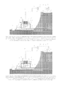
figure 1 , is constructed by twotanks 1 and 2. The tank 1 is partly opened in that way so that it floats afloat a dam reservoir 41 and is permanently connected with a piston 8 which is closed intank 2. Tank 1 is connected through pipes 13 and 12 with pipe 19. Water from tank 1 is possible to desist through pipes 13, 12 and 19 into Hydroelectric Power Station 43.Tank 2 is connected through pipes 20 and 21 with a compressed air tank 6 which is through pipe 48 joined on Hydroelectric Power Station 43. The whole Hydraulic propulsion is equipped with aclosing valves system 29, 30, 31, 32, 33, 34, 40, 46 and with a system of controllable one-way valves 35 and 36. - Tank 1 is from ¾ flooded with water from a dam reservoir 41 and it floats afloat, see
figure 2 . The force keeping tank 1 afloat a dam reservoir 41 is given by an Archimedes principle. In case that the whole construction of the tank 1 would have no weight, the water level in tank 1 would be at the same level, like a water level in a dam reservoir 41. Whereas a tank construction 1 has a weight there will arise a level difference, which is determined by a weight of a tank construction 1 , seefigure 2 . Tank 1 is tied so that it can move only vertically (up and down).Tank 2 is firmly fastened so that it cannot move. - The Hydraulic propulsion works in two consecutive and still repeating cycles. In the first working cycle, tank 1 is flooded from ¾ with water, see
figure 2 . Next, closing valves will be closed 29, 30, 31, 34, 39 and closing valves will be opened 32, 33, 40. A space oftank 2 above the piston 8 is totally closed and filled up with atmospheric air. Water from tank 1 is desisted to turbines in Hydroelectric Power Station 43 through pipes 13, 12 and 19. Desisting of water from tank 1 will cause, that lifting force will lift tank upwards. Level difference of tank 1 and dam reservoir 41 remain the same, it is due to the weight of a tank construction 1. Tank 1 is firmly connected with the piston 8 placed intank 2 whose subsequent motion causes a pressure alteration of a closed atmospheric air. Through opened closing valve 33 and controllable one-way valve 35, compressed air will get to compressed air tank 6, from which it is brought to Hydroelectric Power Station 43 through the controllable one-way valve 36, where through high-pressure turbines it helps water turbines to rotate electrical generators (high-pressure turbine can be installed on shaft common with the water turbine, which rotates a rotor of an electric generator). - In the second working cycle, see
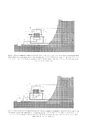
figure 4 , closing valves (primarily opened) will be closed 32, 33 and 40. At the same time, closing valves will be opened 29, 30, 31, 34 and 39. Closing valves which are opened 29 and 30 cause filling tank 1 with water from a dam reservoir 41, which will sink down owing to its weight whereon gravitation force takes an effect. Closed atmospheric air in a lower part oftank 2 is compressed by the motion of a piston 8. The motion of a piston 8 causes pressure alteration of closed atmospheric air. Through the opened closing valve 31 and controllable one-way valve 35, compressed air will get into compressed air tank 6 where it is led in to Hydroelectric Power Station 43, where through high pressure turbines it helps the water turbines to rotate electrical generators. - The Hydraulic propulsion uses two new forces that they have not been used for electricity production up to now - a lifting force effecting tank 1 which cause its lifting in the first working cycle and a gravitation force effecting heavy tank construction 1, causing its back falling by watering in the second working cycle.
- The Hydraulic propulsion is possible to modify so that it would be possible to use also without high pressure turbine. By one of possible configuration, that does not use high pressure turbine, is presented on
figure 6 . In this configuration is the Hydraulic propulsion extended over a tank 3 which is equipped by a sliding piston 7, divided a tank into two parts (left and right). At each part of tank 3 there are joined two pipes on the left side 15, 18 and two pipes on the right side 14, 17. Pipes 14 and 15 are joined on pipe 12 which draws water from a dam reservoir 41. Pipes 17 and 18 are joined on a pipe 19 which leads water into Hydroelectric Power Station 43. On a piston 7 is fastened a connecting rod 11 which goes through a tank 3 and it is constructed so that water from a tank 3 cannot run out to the surroundings, also in the event of its linear motion. On both sides of a connecting rod 11 are fastened pistons 9 and 10 which are closed in tanks 4 and 5. Tanks 4 and 5 are connected through pipes 22 in compressed air tank 6. The tank 1 is partly opened so that it floats afloat a dam reservoir 41 and is firmly connected with a piston 8 which is closed in atank 2. Tank 1 is connected by a pipe 13 with a pipe 12. Water from a tank 1 is possible to desist through a pipe 13 and other successive pipes 12, 14, 15, 17, 18 and 19 in Hydroelectric Power Station 43. Atank 2 is connected through pipes 20 a 21 with a festoon on a compressed air tank 6. The whole Hydraulic propulsion is equipped with the closingvalves system 23, 24, 25, 26, 27, 28, 29, 30, 31, 32, 33, 34, 37, 38, 39, 40, 46 and with the system of controllable one-way valves 35, 36. - The Hydraulic propulsion in this organization works again in two consecutive and still repeating cycles. Before starting the system, it is necessary to fill the whole system with water from a dam reservoir, through a pipe 16, closing valve 40 is closed, so that the water from a dam cannot break into tank 1.
- In the first working cycle, tank is from ¾ flooded with water, see
figure 7 , piston 7 is situated on the right side of a tank 3. In this moment, closing valves are closed 23, 25, 27, 29, 30, 31, 32, 34, 37 and 39. At the same time, controllable one-way valves are opened 24, 26, 28, 32, 33, 35, 36 38 and 40. Hydrostatical pressure on the right side of a tank 3 is higher than hydrostatical pressure on the left side which are separated by a piston 7 from each other. The pressure on the right side of a tank 3 causes the piston motion 7 leftwards. The motion of a piston increases a capacity of a right side of a tank 3 which will cause desisting water from a tank 1. Tank 1 is emptying and the lifting force is raising its construction upwards. The tank 1 is firmly connected with a piston 8 intank 2. A space oftank 2 above the piston 8 is totally closed and filled up with atmospheric air. The motion of a piston 8 causes a pressure alteration of closed atmospheric air. Through opened closing valves 33, 38 and through controllable one-way valves 35, 36, compressed air will get into a tank 5 where this pressure alteration influences a piston 10 whose force is transferred through a connecting rod on a piston 7. Pressurized water from the left side of a tank 1 desists through pipes 18 and 19 towards water turbine of Hydroelectric Power Station 43. Right about this force is increasing a pressure in the left side of a tank 1. The end of the first working cycle is described on afigure 8 . - In the second working cycle, see
figure 9 , closing valves will be closed (primarily opened) 24, 26, 28, 32, 33, 35, 36, 38 and 40. At the same time, closing valves will be opened 23, 25, 27, 29, 30, 31, 34, 37 and 39. Hydrostatical pressure on the left side of a tank 3 is higher than hydrostatical pressure on the right side; they are separated by a piston from each other. Pressure on the right side of a tank 3 causes a motion of a piston 7 leftwards. Opened closing valves 29 and 30 will cause filling tank 1 with water from a dam reservoir which will sink down. Atmospheric air closed in the lower part of atank 2 is compressed by gravitation force caused by the weight of atank construction 2 which is firmly connected with a piston 8. The motion of a piston 8 causes a pressure alteration of an atmospheric air which is closed. Through opened closing valves 31, 37 and through controllable one-way valves 35, 36 will a compressed air get into a tank 4 where this pressure alteration influences a piston 9 whose force is transferred by a connecting rod 11 on a piston 7. Pressurized water from the right side of a tank 3 is desisted from pipes 17 and 19 towards turbines of Hydroelectric Power Station 43. This implies that if we want both working cycles to be the same, the weight of a tank construction will have to be equal to the weight of water which will be equal to the maximum possible flow rate through the turbine per unit of a time. - In the
figure 1 it is possible to see that to the pipes 12 is connected special pipe 45 which is directly joined through closing valve 46 into Hydroelectric Power Station 43. Pipe 45 serves to faster water desisting in the first working cycle, whereby a motion speed of a tank 1 is gathered toward upwards and subsequent increase of pressure caused by the motion of a piston 8 in atank 2. Water desisting through pipe 45 is used in case of increasing of a flow rate in an affluent into a hydroelectric installation. - Another from possible organization of the Hydraulic propulsion you can see in the
figure 11 . The principle of a plant functioning is identical with previous examples. Instead of compressing atmospheric air is atank 2 with a piston 8 situated under a tank 1. Advantage of this organization is that except of lifting force and gravitation force transferred by the motion oftank 2 hydrostatical force will there also occur in tanks 4 and 5 which will help to eliminate friction caused by the motion of pistons 7, 9 and 10. Disadvantage of this organization is increasing of water flow rate from a tank which is given by a capacity of tanks 4 and 5. - All organizations of Hydraulic propulsion are based on the same principle due to this principle they are increasing Hydroelectric Power Station capacity. Invention uses lifting force affecting a tank 1 which depends on a capacity and on a speed of water desisting from this tank in the first working cycle and on a gravitation force affecting a tank construction 1, causing its reverse falling whereat a tank is repeatedly filled.
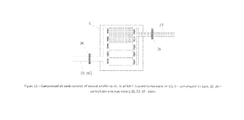
- Compressed air tank 6 is possible to use for storing unexpended compressed air and for controlling a capacity of electric generators through a pressure regulation.
Figure 15 shows how could this tank look. Its indoor air space would consist of several smaller tanks with which have the same extent with an extent of air forced out by a piston 8 in atank 2. - Specific example of engineering solution is schematically described on an attached technical drawing where:
-
Figure 1 Hydraulic propulsion for increase of Hydroelectric Power Station capacity in organization for propulsion of a high pressure turbine -
Figure 2 Hydraulic propulsion for increase of Hydroelectric Power Station capacity in organization for propulsion of a high pressure turbine -the first working cycle -
Figure 3 Hydraulic propulsion for increase of Hydroelectric Power Station capacity in organization for propulsion of a high pressure turbine-the first working cycle, the end -
Figure 4 Hydraulic propulsion for increase of Hydroelectric Power Station capacity in organization for propulsion of a high pressure turbine - the second working cycle -
Figure 5 Hydraulic propulsion for increase of Hydroelectric Power Station capacity in organization for propulsion of a high pressure turbine - the second working cycle, the end -
Figure 6 Hydraulic propulsion for increase of Hydroelectric Power Station capacity in organization for increase of water pressure entering into the water turbine -
Figure 7 Hydraulic propulsion for increase of Hydroelectric Power Station capacity in organization for increase of water pressure entering into the water turbine - the first working cycle -
Figure 8 Hydraulic propulsion for increase of Hydroelectric Power Station capacity in organization for increase of water pressure entering into the water turbine - the first working cycle, the end -
Figure 9 Hydraulic propulsion for increase of Hydroelectric Power Station capacity in organization for increase of water pressure entering into the water turbine - the second working cycle -
Figure 10 Hydraulic propulsion for increase of Hydroelectric Power Station capacity in organization for increase of water pressure entering into the water turbine - the second working cycle, the end -
Figure 11 Hydraulic propulsion in organization for increase of water pressure entering into the water turbine without an atmospheric air-the first working cycle -
Figure 12 Hydraulic propulsion in organization for increase of water pressure entering into the water turbine without an atmospheric air - the first working cycle, the end -
Figure 13 Hydraulic propulsion in organization for increase of water pressure entering into the water turbine without an atmospheric air-the second working cycle -
Figure 14 Hydraulic propulsion in organization for increase of water pressure entering into the water turbine without an atmospheric air - the second working cycle, the endFigure 15 Compressed air tank - Hydraulic propulsion is possible to divide in two basic engineering solutions. First solution, see
figure 1 , uses compressed atmospheric air for the direct rotation of electric generators through high pressure turbines. Second solution, seefigure 6 , uses compressed atmospheric air for a piston capacity in a closed tank with water whereas it is increasing its pressure. Pressurized water is leading direct to water turbines. - First solution of Hydraulic propulsion, see
figure 1 , consists of twotanks 1 and 2. Tank 1 is partly opened so that it floats afloat a dam reservoir 41 and is firmly connected with a piston 8 which is closed in atank 2. Tank 1 is joined through pipes 13, 12 with a pipe 19. Water from a tank 1 is possible to desist through pipes 13, 12 and 19 into Hydroelectric Power Station 43.Tank 2 is joined through pipes 20 and 21 with a compressed air tank 6 which is through pipes 48 connected to Hydroelectric Power Station 43. The whole Hydraulic propulsion is equipped with aclosing valves system 29, 30, 31, 32, 33, 34, 46 and with a system of controllable one-way valves 35 and 36. - Tank 1 is from ¾ flooded with water from a dam reservoir 41 and it floats afloat and is fastened so that it can move just vertically (upwards and downwards).
Tank 2 is fastened so that it cannot move. - The Hydraulic propulsion works in two successive and still repeating cycles. In the first working cycle a tank 1 is from % flooded with water, see
figure 2 . Next, closing valves 29, 30, 31, 34, 39 will be closed and closingvalves 32, 33, 40 will be opened. Area of atank 2 above a piston 8 is wholly closed and filled up with atmospheric air. Water from a tank 1 is desisted through pipes 12, 13 and 19 to turbines into Hydroelectric Power Station 43. Desisting water from a tank 1 will cause that the lifting force is lifting a tank upwards. The difference between water levels of a tank 1 and a dam reservoir stay the same; it is given by a weight of a tank construction 1. A tank 1 is firmly connected with a piston 8 situated in atank 2 whose subsequent motion causes a pressure alteration of an atmospheric air that is closed. Compressed air will get through a closing valve 33 and through a controllable one-way valve 35 to the compressed air tank 6, from that through a controllable one-way valve 36 it is led into Hydroelectric Power Station 43 where through high pressure turbines it helps water turbines to rotate electrical generators. - In the second working cycle, see
figure 4 , closing valves (primarily opened) 32, 33 and 34 will be closed. At the same time closing valves 29, 30, 31, 34 and 39 will be opened. - Closing valves which are opened 29 and 30 will cause filling water from a dam reservoir in tank 1 which will due to its weight sink down, because it is influenced by a gravitation force. Atmospheric air, which is closed in a lower part of a
tank 2, is compressed by the motion of a piston 8. The motion of a piston 8 causes a pressure alteration of a closed atmospheric air. Through a closing valve 31 and controllable one-way valve 35 will compressed air get into a compressed air tank 6 from that it is led into Hydroelectric Power Station 43 where through high pressure turbines it helps water turbines to rotate electrical generators. - Second solution of Hydraulic propulsion, see
figure 6 , consists oftanks 1, 2, 3, 4, 5 and 6. Tank 3 is equipped with a sliding ram 7, divided into two parts (left and right). On each part of a tank 3 are joined two pipes leftwards 15, 18 and two pipes rightwards 14, 17. Pipes 14 and 15 are joined on pipe 12 which take water from a dam reservoir 41. Pipes 17 and 18 are joined on pipe 19 which leads water into the Hydroelectric Power Station 43. On a piston 7 is fastened a connecting rod 11 which passes through a tank 3 and is tightened so that water from a tank 3 could not leak into surroundings, also in case of its linear motion. On each side of a connecting rod 11 are fastened pistons 9 and 10 which are closed in tanks 4 and 5. Tanks 4 and 5 are joined through pipe 22 into a compressed air tank. Tank 1 is partly opened so that it flows afloat a dam reservoir 41 and is firmly connected with a piston 8 which is closed in atank 2. Tank 1 is joined through pipe 13 and 12. Water from a tank 1 is in that way possible to desist through pipe 13 and through coherent pipes 12, 14, 15, 17, 18 and 19 into Hydroelectric Power Station 43.Tank 2 is interconnected through pipes 20 and 21 with balancing compressed air tank 6. The whole Hydraulic propulsion is equipped with closingvalves system - Hydraulic propulsion works in this organization again in two still repeating working cycles. Before starting-up a system it is necessary to fill it up with water from a dam reservoir through pipe 16, closing valve 40 is closed so that water from a dam reservoir could not flooding in a
tank 2. - In the first working cycle the tank is from % flooded with water, see
figure 7 , piston 7 is situated on the right side of a tank 3. In this moment, closing valves are closed 23, 25, 27, 29, 30, 31, 32, 34, 37 and 39. At the same time controllable one-way valves are opened 24, 26, 28, 32, 33, 35, 36, 38 and 40. Hydrostatical pressure on the right side of a tank 3 is higher than hydrostatical pressure on the left side which are separated by a piston 7 from each other. The pressure on the right side of a tank 3 causes the piston 7 motion leftwards. The motion of a piston increases a capacity of a right side of a tank 3 which will cause desisting water from a tank 1. Tank 1 is emptying and the lifting force is raising its construction upwards. Tank 1 is firmly connected with a piston 8 in atank 2. A space of atank 2 above the piston 8 is totally closed and filled up with atmospheric air. The motion of a piston 8 causes a pressure alteration of a closed atmospheric air. Through opened closing valves 33, 38 and through controllable one-way valves 35, 36, compressed air will get into a tank 5 where this pressure alteration influences a piston 10 whose force is transferred through a connecting rod on a piston 7. Pressurized water from the left side of a tank 1 desists through pipes 18 and 19 towards water turbine of Hydroelectric Power Station 43. - In the second working cycle, see
figure 9 , closing valves will be closed (primarily opened) 24, 26, 28, 32, 33, 35, 36, 38 and 40. At the same time, closing valves will be opened 23, 25, 27, 29, 30, 31, 34, 37 and 39. The Hydrostatical pressure on the left side of a tank 3 is higher than hydrostatical pressure on the right side; they are separated by a piston from each other. Pressure on the right side of a tank 3 causes a motion of a piston 7 leftwards. Opened closing valves 29 and 30 will cause filling the tank 1 with water from a dam reservoir which will sink down. Atmospheric air, closed in the lower part of atank 2, is compressed by gravitation force caused by the weight of atank construction 2, which is firmly connected with a piston 8. The motion of a piston 8 causes a pressure alteration of an atmospheric air which is closed. Through opened closing valves 31, 37 and through controllable one-way valves 35, 36 will a compressed air get into a tank 4, where this pressure alteration influences on a piston 9, whose force is transferred by a connecting rod 11 on a piston 7. Pressurized water from the right side of a tank 3 desists from the pipes 17 and 19 towards the turbines of Hydroelectric Power Station 43. - The Hydraulic propulsion is possible to use as a plant for increasing capacity of Hydroelectric Power Station, eventually it is possible to use it for combined electricity production in connection with water turbine and high pressure turbine. The Hydraulic propulsion is very effective in atmospheric air pressure. The Hydraulic propulsion notably streamlines and increases present electricity production of water resource.
Claims (14)
- The Hydraulic propulsion for increase of Hydroelectric Power Station capacity, see figure 1, which includes it is created of a tank (1), floating on water level of a dam reservoir (41), is equipped with closing valves (29), (30) and joined through pipes (13), (12) and (19) into Hydroelectric Power Station (43) whereas a tank construction (1) is firmly connected with a connecting rod and a piston (8) closed in a tank 2 which is equipped with closing valves (31), (32), (33) and (34) and joined through a pipe (20), (21) into a compressed air tank (6) which is connected to Hydroelectric Power Station (43) through pipe (48).
- The Hydraulic propulsion for increase of Hydroelectric Power Station capacity, see figure 6, which includes it is created of a tank (1), floating on water level of a dam reservoir (41), is equipped with closing valves (29), (30) and joined through pipes (13), (12), (14) and (15) into a tank (3), interconnected through pipes (17), (18), (19) with Hydroelectric Power Station 43 and in which is situated a piston (7), interconnected with a connecting rod (11) and pistons (10) and (9) closed in tanks (4) and (5) which are through pipe (22) joined with compressed air tank (6) which is through pipes (21) and (22) interconnected with a tank (2), equipped with closing valves (31), (32), (33), (34) and in which there is a closed piston (8) which is firmly connected through a connecting rod with a tank (1).
- The Hydraulic propulsion as claimed in claims 1 or 2 which includes that a tank (1) is fastened so that it can move only in a vertical direction.
- The Hydraulic propulsion as claimed in claims 1 or 2 which includes that a tank (1) is fastened so that it can move only in a vertical direction and it is possible to fix it firmly.
- The Hydraulic propulsion as claimed in claim 1 which includes that a tank (1) is possible to fill with water from a dam reservoir (41) through closing valves (29) and (30) and through pipes (13), (12) and (19) which are joined on Hydroelectric Power Station (43), it is possible to desist this water again.
- The Hydraulic propulsion as claimed in claim 2 which includes that a tank (1) is possible to fill with water from a dam reservoir (41) through closing valves (29) and (30) and through pipes (13), (12), (14), (15), (18) and (19) which are joined on Hydroelectric Power Station (43), it is possible to desist this water again.
- The Hydraulic propulsion as claimed in claims 1 or 2 which includes that a tank (2) is possible to fill with atmospheric air through closing valves (32) and (34).
- The Hydraulic propulsion as claimed in claim 2 which includes that tanks (4) and (5) are possible to fill with atmospheric air through closing valves (27) and (28), eventually it is possible to hold atmospheric air inside of these tanks.
- The Hydraulic propulsion as claimed in claims 1 or 2, see figure 2 or figure 7 which includes that water desisting from a tank (1) it is moving upwards whereas a piston 8 is closed in a fixed tank (2) with opened closing valves (32), (33) and closed closing valves (31), (34) causes pressure increasing of atmospheric air which is consequently transferred through pipe (21) into a compressed air tank (6).
- The Hydraulic propulsion as claimed in claims 1 or 2, see figure 4 or figure 9 which includes that by filling water from a dam reservoir into a tank (1) through opened closing valves (29), (30) and closed closing valve (40) it is moving downwards whereas a piston (8) is closed in a fixed tank (2) with opened closing valves (31), (34) and closed closing valves (32), (33) causes pressure increasing of atmospheric air which is subsequently transferred through pipes (20), (21) into a compressed air tank (6).
- The Hydraulic propulsion as claimed in claim 1 which includes that from compressed air tank (6) is compressed air brought to Hydroelectric Power Station (43) through controllable one-way valve (36) and through pipe (48) where its helps water turbines to rotate electrical generators.
- The Hydraulic propulsion as claimed in claim 2, see figure 7 which includes that from compressed air tank (6) is atmospheric air brought into a tank (5) through controllable one-way valve (36) and through pipe (22) with opened closing valve (38) and closed closing valve (37) in a tank where a piston (10) is situated which by its motion influences a connecting rod (11) and a piston (7) closed in a tank (3) and it helps in that way to increase water pressure flowing out a tank (3) through pipes (18) and (19) to water turbines of Hydroelectric Power Station (43).
- The Hydraulic propulsion as claimed in claim 2, see figure 9 which includes that from compressed air tank (6) is atmospheric air brought into a tank (5) through controllable one-way valve (36) and through pipe (22) with opened closing valve (37) and closed closing valve (38) in a tank where is situated a piston (9) which by its motion influences a connecting rod (11) and a piston (7) closed in a tank (3) and it helps in that way to increase water pressure flowing out a tank (3) through pipes (17) and (19) to water turbines of Hydroelectric Power Station (43).
- The Hydraulic propulsion as claimed in claims 1 or 2 which includes that on pipe (12) is joined pipe (45) which is controlled by closing valve (46) and it helps to the faster desisting of a tank (1).
Priority Applications (5)
| Application Number | Priority Date | Filing Date | Title |
|---|---|---|---|
| SI200930395T SI2302202T1 (en) | 2009-09-24 | 2009-09-24 | Hydraulic propulsion for increases of hydroelektric power station capacity |
| EP09466021A EP2302202B1 (en) | 2009-09-24 | 2009-09-24 | Hydraulic propulsion for increases of hydroelektric power station capacity |
| ES09466021T ES2393945T3 (en) | 2009-09-24 | 2009-09-24 | Hydraulic propulsion to increase the capacity of hydroelectric power plants |
| DK09466021.4T DK2302202T3 (en) | 2009-09-24 | 2009-09-24 | Hydraulic propulsion for increasing hydroelectric power plant capacity |
| PT94660214T PT2302202E (en) | 2009-09-24 | 2009-09-24 | Hydraulic propulsion for increases of hydroelektric power station capacity |
Applications Claiming Priority (1)
| Application Number | Priority Date | Filing Date | Title |
|---|---|---|---|
| EP09466021A EP2302202B1 (en) | 2009-09-24 | 2009-09-24 | Hydraulic propulsion for increases of hydroelektric power station capacity |
Publications (2)
| Publication Number | Publication Date |
|---|---|
| EP2302202A1 true EP2302202A1 (en) | 2011-03-30 |
| EP2302202B1 EP2302202B1 (en) | 2012-08-29 |
Family
ID=42751702
Family Applications (1)
| Application Number | Title | Priority Date | Filing Date |
|---|---|---|---|
| EP09466021A Active EP2302202B1 (en) | 2009-09-24 | 2009-09-24 | Hydraulic propulsion for increases of hydroelektric power station capacity |
Country Status (5)
| Country | Link |
|---|---|
| EP (1) | EP2302202B1 (en) |
| DK (1) | DK2302202T3 (en) |
| ES (1) | ES2393945T3 (en) |
| PT (1) | PT2302202E (en) |
| SI (1) | SI2302202T1 (en) |
Cited By (5)
| Publication number | Priority date | Publication date | Assignee | Title |
|---|---|---|---|---|
| EP2821313A2 (en) | 2013-07-02 | 2015-01-07 | Siemens Schweiz AG | Apparatus and method for operating functional units arranged in a decentralised manner |
| US20150113968A1 (en) * | 2009-12-21 | 2015-04-30 | Ronald Kurt Christensen | Transient liquid pressure power generation systems and associated devices and methods |
| CN106870259A (en) * | 2017-02-22 | 2017-06-20 | 华北电力大学 | A kind of two-part energy-storage system based on constant-pressure gas storage |
| US9915179B2 (en) | 2009-12-21 | 2018-03-13 | Ronald Kurt Christensen | Transient liquid pressure power generation systems and associated devices and methods |
| RU181163U1 (en) * | 2018-01-19 | 2018-07-05 | Юрий Арсентьевич Чашков | HYDROMECHANICAL ENERGY STORAGE (NEGM) |
Citations (3)
| Publication number | Priority date | Publication date | Assignee | Title |
|---|---|---|---|---|
| GB2001395A (en) * | 1977-07-25 | 1979-01-31 | Norton J | System for generating electrical energy utilizing combined water power and combustible fuel sources |
| DE10011197A1 (en) * | 2000-03-08 | 2001-09-20 | Walter Banz | Running water power installation derives energy from running water course and involves water course accumulated by weir on upper water plane in upper water side channel |
| WO2007076866A1 (en) * | 2005-12-30 | 2007-07-12 | Pedersen Joergen | Clean energy power plant |
-
2009
- 2009-09-24 ES ES09466021T patent/ES2393945T3/en active Active
- 2009-09-24 DK DK09466021.4T patent/DK2302202T3/en active
- 2009-09-24 SI SI200930395T patent/SI2302202T1/en unknown
- 2009-09-24 PT PT94660214T patent/PT2302202E/en unknown
- 2009-09-24 EP EP09466021A patent/EP2302202B1/en active Active
Patent Citations (3)
| Publication number | Priority date | Publication date | Assignee | Title |
|---|---|---|---|---|
| GB2001395A (en) * | 1977-07-25 | 1979-01-31 | Norton J | System for generating electrical energy utilizing combined water power and combustible fuel sources |
| DE10011197A1 (en) * | 2000-03-08 | 2001-09-20 | Walter Banz | Running water power installation derives energy from running water course and involves water course accumulated by weir on upper water plane in upper water side channel |
| WO2007076866A1 (en) * | 2005-12-30 | 2007-07-12 | Pedersen Joergen | Clean energy power plant |
Cited By (8)
| Publication number | Priority date | Publication date | Assignee | Title |
|---|---|---|---|---|
| US20150113968A1 (en) * | 2009-12-21 | 2015-04-30 | Ronald Kurt Christensen | Transient liquid pressure power generation systems and associated devices and methods |
| US9739268B2 (en) * | 2009-12-21 | 2017-08-22 | Ronald Kurt Christensen | Transient liquid pressure power generation systems and associated devices and methods |
| US9915179B2 (en) | 2009-12-21 | 2018-03-13 | Ronald Kurt Christensen | Transient liquid pressure power generation systems and associated devices and methods |
| EP2821313A2 (en) | 2013-07-02 | 2015-01-07 | Siemens Schweiz AG | Apparatus and method for operating functional units arranged in a decentralised manner |
| WO2015000757A1 (en) | 2013-07-02 | 2015-01-08 | Siemens Schweiz Ag | Device and method for operating functional units arranged in a decentralized manner |
| CN106870259A (en) * | 2017-02-22 | 2017-06-20 | 华北电力大学 | A kind of two-part energy-storage system based on constant-pressure gas storage |
| CN106870259B (en) * | 2017-02-22 | 2020-02-21 | 华北电力大学 | Two-section type energy storage system based on constant-pressure gas storage |
| RU181163U1 (en) * | 2018-01-19 | 2018-07-05 | Юрий Арсентьевич Чашков | HYDROMECHANICAL ENERGY STORAGE (NEGM) |
Also Published As
| Publication number | Publication date |
|---|---|
| EP2302202B1 (en) | 2012-08-29 |
| ES2393945T3 (en) | 2013-01-02 |
| SI2302202T1 (en) | 2012-12-31 |
| PT2302202E (en) | 2012-12-06 |
| DK2302202T3 (en) | 2012-11-26 |
Similar Documents
| Publication | Publication Date | Title |
|---|---|---|
| ES2309744T3 (en) | MODULAR SYSTEM FOR THE PRODUCTION OF ELECTRICAL ENERGY FROM THE MOVEMENT OF THE WAVES. | |
| EP3256716B1 (en) | Hydro-pneumatic energy storage system | |
| FI79892B (en) | HYDROPNEUMATISK VATTENKRAFTMASKIN. | |
| US20090121486A1 (en) | Tidal Power System | |
| US8525365B2 (en) | Device for generating electric energy from a renewable source | |
| JP2020045904A (en) | Wave energy conversion device | |
| US20090021012A1 (en) | Integrated wind-power electrical generation and compressed air energy storage system | |
| EP2302202A1 (en) | Hydraulic propulsion for increases of hydroelektric power station capacity | |
| US9261069B2 (en) | Sloping wall channel | |
| US10801476B2 (en) | Advanced gravity-moment-hydro power system | |
| NZ565291A (en) | Power generation using immersed vessel(s) using off-peak electricity for pumping out water from vessel and to generate electricity via turbine during peak demand to feed to grid | |
| JP2016517923A (en) | Submersible hydroelectric generator device and method for draining water from such device | |
| WO2015174726A1 (en) | Energy storage apparatus using power generation turbine and compressed gas by pump | |
| WO2011141691A2 (en) | Tidal or wave energy harnessing device | |
| JP2017520718A (en) | A device for converting or absorbing energy from a moving body of water | |
| KR102591408B1 (en) | Wave absorption conversion device and power generation system | |
| KR20150082531A (en) | Floating buoy turnover hydraulic power output device | |
| CA3188714A1 (en) | An improved apparatus and method for extracting energy from a fluid | |
| GB2472055A (en) | Dual bellows pneumatic wave energy device | |
| JP2009167925A (en) | Hydraulic power generation method and device using tidal energy | |
| Plummer et al. | Power systems | |
| WO2022248417A1 (en) | Hermetic cap tidal pulse responder | |
| KR910000983B1 (en) | Wave-power plants | |
| GB2531596A (en) | Tidal turbine system | |
| RU2633497C2 (en) | Tidal power plant power module |
Legal Events
| Date | Code | Title | Description |
|---|---|---|---|
| PUAI | Public reference made under article 153(3) epc to a published international application that has entered the european phase |
Free format text: ORIGINAL CODE: 0009012 |
|
| AK | Designated contracting states |
Kind code of ref document: A1 Designated state(s): AT BE BG CH CY CZ DE DK EE ES FI FR GB GR HR HU IE IS IT LI LT LU LV MC MK MT NL NO PL PT RO SE SI SK SM TR |
|
| AX | Request for extension of the european patent |
Extension state: AL BA RS |
|
| 17P | Request for examination filed |
Effective date: 20110505 |
|
| 17Q | First examination report despatched |
Effective date: 20111116 |
|
| GRAP | Despatch of communication of intention to grant a patent |
Free format text: ORIGINAL CODE: EPIDOSNIGR1 |
|
| GRAS | Grant fee paid |
Free format text: ORIGINAL CODE: EPIDOSNIGR3 |
|
| GRAA | (expected) grant |
Free format text: ORIGINAL CODE: 0009210 |
|
| AK | Designated contracting states |
Kind code of ref document: B1 Designated state(s): AT BE BG CH CY CZ DE DK EE ES FI FR GB GR HR HU IE IS IT LI LT LU LV MC MK MT NL NO PL PT RO SE SI SK SM TR |
|
| REG | Reference to a national code |
Ref country code: GB Ref legal event code: FG4D |
|
| REG | Reference to a national code |
Ref country code: CH Ref legal event code: EP |
|
| REG | Reference to a national code |
Ref country code: AT Ref legal event code: REF Ref document number: 573229 Country of ref document: AT Kind code of ref document: T Effective date: 20120915 |
|
| REG | Reference to a national code |
Ref country code: IE Ref legal event code: FG4D |
|
| REG | Reference to a national code |
Ref country code: DE Ref legal event code: R096 Ref document number: 602009009268 Country of ref document: DE Effective date: 20121025 |
|
| REG | Reference to a national code |
Ref country code: CH Ref legal event code: NV Representative=s name: MICHELI AND CIE SA, CH |
|
| REG | Reference to a national code |
Ref country code: RO Ref legal event code: EPE |
|
| REG | Reference to a national code |
Ref country code: DK Ref legal event code: T3 |
|
| REG | Reference to a national code |
Ref country code: SE Ref legal event code: TRGR |
|
| REG | Reference to a national code |
Ref country code: PT Ref legal event code: SC4A Free format text: AVAILABILITY OF NATIONAL TRANSLATION Effective date: 20121121 |
|
| REG | Reference to a national code |
Ref country code: NL Ref legal event code: T3 |
|
| REG | Reference to a national code |
Ref country code: ES Ref legal event code: FG2A Ref document number: 2393945 Country of ref document: ES Kind code of ref document: T3 Effective date: 20130102 |
|
| REG | Reference to a national code |
Ref country code: LT Ref legal event code: MG4D Effective date: 20120829 |
|
| PG25 | Lapsed in a contracting state [announced via postgrant information from national office to epo] |
Ref country code: NO Free format text: LAPSE BECAUSE OF FAILURE TO SUBMIT A TRANSLATION OF THE DESCRIPTION OR TO PAY THE FEE WITHIN THE PRESCRIBED TIME-LIMIT Effective date: 20121129 Ref country code: IS Free format text: LAPSE BECAUSE OF FAILURE TO SUBMIT A TRANSLATION OF THE DESCRIPTION OR TO PAY THE FEE WITHIN THE PRESCRIBED TIME-LIMIT Effective date: 20121229 Ref country code: HR Free format text: LAPSE BECAUSE OF FAILURE TO SUBMIT A TRANSLATION OF THE DESCRIPTION OR TO PAY THE FEE WITHIN THE PRESCRIBED TIME-LIMIT Effective date: 20120829 Ref country code: LT Free format text: LAPSE BECAUSE OF FAILURE TO SUBMIT A TRANSLATION OF THE DESCRIPTION OR TO PAY THE FEE WITHIN THE PRESCRIBED TIME-LIMIT Effective date: 20120829 |
|
| PG25 | Lapsed in a contracting state [announced via postgrant information from national office to epo] |
Ref country code: GR Free format text: LAPSE BECAUSE OF FAILURE TO SUBMIT A TRANSLATION OF THE DESCRIPTION OR TO PAY THE FEE WITHIN THE PRESCRIBED TIME-LIMIT Effective date: 20121130 Ref country code: LV Free format text: LAPSE BECAUSE OF FAILURE TO SUBMIT A TRANSLATION OF THE DESCRIPTION OR TO PAY THE FEE WITHIN THE PRESCRIBED TIME-LIMIT Effective date: 20120829 |
|
| REG | Reference to a national code |
Ref country code: SK Ref legal event code: T3 Ref document number: E 13355 Country of ref document: SK |
|
| PG25 | Lapsed in a contracting state [announced via postgrant information from national office to epo] |
Ref country code: EE Free format text: LAPSE BECAUSE OF FAILURE TO SUBMIT A TRANSLATION OF THE DESCRIPTION OR TO PAY THE FEE WITHIN THE PRESCRIBED TIME-LIMIT Effective date: 20120829 Ref country code: MC Free format text: LAPSE BECAUSE OF NON-PAYMENT OF DUE FEES Effective date: 20120930 |
|
| PG25 | Lapsed in a contracting state [announced via postgrant information from national office to epo] |
Ref country code: PL Free format text: LAPSE BECAUSE OF FAILURE TO SUBMIT A TRANSLATION OF THE DESCRIPTION OR TO PAY THE FEE WITHIN THE PRESCRIBED TIME-LIMIT Effective date: 20120829 |
|
| REG | Reference to a national code |
Ref country code: IE Ref legal event code: MM4A |
|
| PLBE | No opposition filed within time limit |
Free format text: ORIGINAL CODE: 0009261 |
|
| STAA | Information on the status of an ep patent application or granted ep patent |
Free format text: STATUS: NO OPPOSITION FILED WITHIN TIME LIMIT |
|
| PG25 | Lapsed in a contracting state [announced via postgrant information from national office to epo] |
Ref country code: IE Free format text: LAPSE BECAUSE OF NON-PAYMENT OF DUE FEES Effective date: 20120924 |
|
| 26N | No opposition filed |
Effective date: 20130530 |
|
| REG | Reference to a national code |
Ref country code: DE Ref legal event code: R097 Ref document number: 602009009268 Country of ref document: DE Effective date: 20130530 |
|
| REG | Reference to a national code |
Ref country code: HU Ref legal event code: AG4A Ref document number: E016735 Country of ref document: HU |
|
| PG25 | Lapsed in a contracting state [announced via postgrant information from national office to epo] |
Ref country code: MT Free format text: LAPSE BECAUSE OF FAILURE TO SUBMIT A TRANSLATION OF THE DESCRIPTION OR TO PAY THE FEE WITHIN THE PRESCRIBED TIME-LIMIT Effective date: 20120829 Ref country code: CY Free format text: LAPSE BECAUSE OF FAILURE TO SUBMIT A TRANSLATION OF THE DESCRIPTION OR TO PAY THE FEE WITHIN THE PRESCRIBED TIME-LIMIT Effective date: 20120829 |
|
| PG25 | Lapsed in a contracting state [announced via postgrant information from national office to epo] |
Ref country code: SM Free format text: LAPSE BECAUSE OF FAILURE TO SUBMIT A TRANSLATION OF THE DESCRIPTION OR TO PAY THE FEE WITHIN THE PRESCRIBED TIME-LIMIT Effective date: 20120829 Ref country code: LU Free format text: LAPSE BECAUSE OF NON-PAYMENT OF DUE FEES Effective date: 20120924 |
|
| PGFP | Annual fee paid to national office [announced via postgrant information from national office to epo] |
Ref country code: RO Payment date: 20140915 Year of fee payment: 6 Ref country code: NL Payment date: 20140919 Year of fee payment: 6 Ref country code: CH Payment date: 20140916 Year of fee payment: 6 Ref country code: FI Payment date: 20140922 Year of fee payment: 6 Ref country code: BG Payment date: 20140905 Year of fee payment: 6 Ref country code: DK Payment date: 20140925 Year of fee payment: 6 |
|
| PGFP | Annual fee paid to national office [announced via postgrant information from national office to epo] |
Ref country code: ES Payment date: 20140922 Year of fee payment: 6 Ref country code: SI Payment date: 20140918 Year of fee payment: 6 |
|
| PGFP | Annual fee paid to national office [announced via postgrant information from national office to epo] |
Ref country code: PT Payment date: 20140324 Year of fee payment: 6 Ref country code: IT Payment date: 20140924 Year of fee payment: 6 |
|
| PGFP | Annual fee paid to national office [announced via postgrant information from national office to epo] |
Ref country code: BE Payment date: 20140919 Year of fee payment: 6 |
|
| PG25 | Lapsed in a contracting state [announced via postgrant information from national office to epo] |
Ref country code: MK Free format text: LAPSE BECAUSE OF FAILURE TO SUBMIT A TRANSLATION OF THE DESCRIPTION OR TO PAY THE FEE WITHIN THE PRESCRIBED TIME-LIMIT Effective date: 20120829 |
|
| PGFP | Annual fee paid to national office [announced via postgrant information from national office to epo] |
Ref country code: TR Payment date: 20130924 Year of fee payment: 5 |
|
| REG | Reference to a national code |
Ref country code: PT Ref legal event code: MM4A Free format text: LAPSE DUE TO NON-PAYMENT OF FEES Effective date: 20160324 |
|
| REG | Reference to a national code |
Ref country code: DK Ref legal event code: EBP Effective date: 20150930 |
|
| PG25 | Lapsed in a contracting state [announced via postgrant information from national office to epo] |
Ref country code: IT Free format text: LAPSE BECAUSE OF NON-PAYMENT OF DUE FEES Effective date: 20150924 |
|
| REG | Reference to a national code |
Ref country code: CH Ref legal event code: PL |
|
| PG25 | Lapsed in a contracting state [announced via postgrant information from national office to epo] |
Ref country code: RO Free format text: LAPSE BECAUSE OF NON-PAYMENT OF DUE FEES Effective date: 20150924 Ref country code: FI Free format text: LAPSE BECAUSE OF NON-PAYMENT OF DUE FEES Effective date: 20150924 Ref country code: PT Free format text: LAPSE BECAUSE OF NON-PAYMENT OF DUE FEES Effective date: 20160324 |
|
| REG | Reference to a national code |
Ref country code: NL Ref legal event code: MM Effective date: 20151001 |
|
| PG25 | Lapsed in a contracting state [announced via postgrant information from national office to epo] |
Ref country code: CH Free format text: LAPSE BECAUSE OF NON-PAYMENT OF DUE FEES Effective date: 20150930 Ref country code: LI Free format text: LAPSE BECAUSE OF NON-PAYMENT OF DUE FEES Effective date: 20150930 |
|
| REG | Reference to a national code |
Ref country code: SI Ref legal event code: KO00 Effective date: 20160606 |
|
| PG25 | Lapsed in a contracting state [announced via postgrant information from national office to epo] |
Ref country code: SI Free format text: LAPSE BECAUSE OF NON-PAYMENT OF DUE FEES Effective date: 20150925 Ref country code: NL Free format text: LAPSE BECAUSE OF NON-PAYMENT OF DUE FEES Effective date: 20151001 |
|
| REG | Reference to a national code |
Ref country code: FR Ref legal event code: PLFP Year of fee payment: 8 |
|
| PG25 | Lapsed in a contracting state [announced via postgrant information from national office to epo] |
Ref country code: BG Free format text: LAPSE BECAUSE OF NON-PAYMENT OF DUE FEES Effective date: 20160630 Ref country code: DK Free format text: LAPSE BECAUSE OF NON-PAYMENT OF DUE FEES Effective date: 20150930 |
|
| PGFP | Annual fee paid to national office [announced via postgrant information from national office to epo] |
Ref country code: HU Payment date: 20160924 Year of fee payment: 8 Ref country code: SK Payment date: 20160919 Year of fee payment: 8 |
|
| REG | Reference to a national code |
Ref country code: ES Ref legal event code: FD2A Effective date: 20170227 |
|
| PG25 | Lapsed in a contracting state [announced via postgrant information from national office to epo] |
Ref country code: ES Free format text: LAPSE BECAUSE OF NON-PAYMENT OF DUE FEES Effective date: 20150925 |
|
| PG25 | Lapsed in a contracting state [announced via postgrant information from national office to epo] |
Ref country code: BE Free format text: LAPSE BECAUSE OF NON-PAYMENT OF DUE FEES Effective date: 20150930 |
|
| PG25 | Lapsed in a contracting state [announced via postgrant information from national office to epo] |
Ref country code: TR Free format text: LAPSE BECAUSE OF NON-PAYMENT OF DUE FEES Effective date: 20150924 |
|
| REG | Reference to a national code |
Ref country code: FR Ref legal event code: PLFP Year of fee payment: 9 |
|
| PGFP | Annual fee paid to national office [announced via postgrant information from national office to epo] |
Ref country code: AT Payment date: 20170919 Year of fee payment: 9 |
|
| REG | Reference to a national code |
Ref country code: SK Ref legal event code: MM4A Ref document number: E 13355 Country of ref document: SK Effective date: 20170924 |
|
| PG25 | Lapsed in a contracting state [announced via postgrant information from national office to epo] |
Ref country code: SK Free format text: LAPSE BECAUSE OF NON-PAYMENT OF DUE FEES Effective date: 20170924 |
|
| PG25 | Lapsed in a contracting state [announced via postgrant information from national office to epo] |
Ref country code: HU Free format text: LAPSE BECAUSE OF NON-PAYMENT OF DUE FEES Effective date: 20170925 |
|
| REG | Reference to a national code |
Ref country code: FR Ref legal event code: PLFP Year of fee payment: 10 |
|
| REG | Reference to a national code |
Ref country code: AT Ref legal event code: MM01 Ref document number: 573229 Country of ref document: AT Kind code of ref document: T Effective date: 20180924 |
|
| PG25 | Lapsed in a contracting state [announced via postgrant information from national office to epo] |
Ref country code: AT Free format text: LAPSE BECAUSE OF NON-PAYMENT OF DUE FEES Effective date: 20180924 |
|
| PGFP | Annual fee paid to national office [announced via postgrant information from national office to epo] |
Ref country code: SE Payment date: 20210922 Year of fee payment: 13 |
|
| PGFP | Annual fee paid to national office [announced via postgrant information from national office to epo] |
Ref country code: FR Payment date: 20220929 Year of fee payment: 14 |
|
| REG | Reference to a national code |
Ref country code: SE Ref legal event code: EUG |
|
| PG25 | Lapsed in a contracting state [announced via postgrant information from national office to epo] |
Ref country code: SE Free format text: LAPSE BECAUSE OF NON-PAYMENT OF DUE FEES Effective date: 20220925 |
|
| PGFP | Annual fee paid to national office [announced via postgrant information from national office to epo] |
Ref country code: GB Payment date: 20230920 Year of fee payment: 15 Ref country code: CZ Payment date: 20230921 Year of fee payment: 15 |
|
| PGFP | Annual fee paid to national office [announced via postgrant information from national office to epo] |
Ref country code: DE Payment date: 20230921 Year of fee payment: 15 |