EP2302194A1 - A pump unit - Google Patents
A pump unit Download PDFInfo
- Publication number
- EP2302194A1 EP2302194A1 EP10191439A EP10191439A EP2302194A1 EP 2302194 A1 EP2302194 A1 EP 2302194A1 EP 10191439 A EP10191439 A EP 10191439A EP 10191439 A EP10191439 A EP 10191439A EP 2302194 A1 EP2302194 A1 EP 2302194A1
- Authority
- EP
- European Patent Office
- Prior art keywords
- pumping chamber
- inlet valve
- plunger
- fuel
- pump unit
- Prior art date
- Legal status (The legal status is an assumption and is not a legal conclusion. Google has not performed a legal analysis and makes no representation as to the accuracy of the status listed.)
- Granted
Links
- 238000005086 pumping Methods 0.000 claims abstract description 153
- 239000000446 fuel Substances 0.000 claims abstract description 97
- 239000012530 fluid Substances 0.000 claims abstract description 36
- 238000007789 sealing Methods 0.000 claims abstract description 24
- 230000037361 pathway Effects 0.000 claims abstract description 17
- 238000002347 injection Methods 0.000 claims abstract description 11
- 239000007924 injection Substances 0.000 claims abstract description 11
- 230000004044 response Effects 0.000 claims description 3
- 239000000463 material Substances 0.000 description 27
- 238000004891 communication Methods 0.000 description 17
- 230000003068 static effect Effects 0.000 description 13
- 230000009471 action Effects 0.000 description 4
- 238000003754 machining Methods 0.000 description 3
- 238000004519 manufacturing process Methods 0.000 description 3
- 238000011144 upstream manufacturing Methods 0.000 description 3
- 229910000831 Steel Inorganic materials 0.000 description 2
- 238000002485 combustion reaction Methods 0.000 description 2
- 230000006835 compression Effects 0.000 description 2
- 238000007906 compression Methods 0.000 description 2
- 230000003071 parasitic effect Effects 0.000 description 2
- 230000009467 reduction Effects 0.000 description 2
- 239000010959 steel Substances 0.000 description 2
- 230000008901 benefit Effects 0.000 description 1
- 230000008859 change Effects 0.000 description 1
- 238000010276 construction Methods 0.000 description 1
- 230000003247 decreasing effect Effects 0.000 description 1
- 238000013461 design Methods 0.000 description 1
- 238000007599 discharging Methods 0.000 description 1
- 238000006073 displacement reaction Methods 0.000 description 1
- 238000005553 drilling Methods 0.000 description 1
- 238000005242 forging Methods 0.000 description 1
- 238000000034 method Methods 0.000 description 1
- 238000012986 modification Methods 0.000 description 1
- 230000004048 modification Effects 0.000 description 1
- 230000008569 process Effects 0.000 description 1
- 238000012545 processing Methods 0.000 description 1
Images


Classifications
-
- F—MECHANICAL ENGINEERING; LIGHTING; HEATING; WEAPONS; BLASTING
- F02—COMBUSTION ENGINES; HOT-GAS OR COMBUSTION-PRODUCT ENGINE PLANTS
- F02M—SUPPLYING COMBUSTION ENGINES IN GENERAL WITH COMBUSTIBLE MIXTURES OR CONSTITUENTS THEREOF
- F02M59/00—Pumps specially adapted for fuel-injection and not provided for in groups F02M39/00 -F02M57/00, e.g. rotary cylinder-block type of pumps
- F02M59/20—Varying fuel delivery in quantity or timing
- F02M59/36—Varying fuel delivery in quantity or timing by variably-timed valves controlling fuel passages to pumping elements or overflow passages
- F02M59/361—Valves being actuated mechanically
-
- F—MECHANICAL ENGINEERING; LIGHTING; HEATING; WEAPONS; BLASTING
- F02—COMBUSTION ENGINES; HOT-GAS OR COMBUSTION-PRODUCT ENGINE PLANTS
- F02M—SUPPLYING COMBUSTION ENGINES IN GENERAL WITH COMBUSTIBLE MIXTURES OR CONSTITUENTS THEREOF
- F02M59/00—Pumps specially adapted for fuel-injection and not provided for in groups F02M39/00 -F02M57/00, e.g. rotary cylinder-block type of pumps
- F02M59/20—Varying fuel delivery in quantity or timing
- F02M59/36—Varying fuel delivery in quantity or timing by variably-timed valves controlling fuel passages to pumping elements or overflow passages
- F02M59/365—Varying fuel delivery in quantity or timing by variably-timed valves controlling fuel passages to pumping elements or overflow passages valves being actuated by the fluid pressure produced in an auxiliary pump, e.g. pumps with differential pistons; Regulated pressure of supply pump actuating a metering valve, e.g. a sleeve surrounding the pump piston
-
- F—MECHANICAL ENGINEERING; LIGHTING; HEATING; WEAPONS; BLASTING
- F02—COMBUSTION ENGINES; HOT-GAS OR COMBUSTION-PRODUCT ENGINE PLANTS
- F02M—SUPPLYING COMBUSTION ENGINES IN GENERAL WITH COMBUSTIBLE MIXTURES OR CONSTITUENTS THEREOF
- F02M59/00—Pumps specially adapted for fuel-injection and not provided for in groups F02M39/00 -F02M57/00, e.g. rotary cylinder-block type of pumps
- F02M59/44—Details, components parts, or accessories not provided for in, or of interest apart from, the apparatus of groups F02M59/02 - F02M59/42; Pumps having transducers, e.g. to measure displacement of pump rack or piston
- F02M59/442—Details, components parts, or accessories not provided for in, or of interest apart from, the apparatus of groups F02M59/02 - F02M59/42; Pumps having transducers, e.g. to measure displacement of pump rack or piston means preventing fuel leakage around pump plunger, e.g. fluid barriers
-
- F—MECHANICAL ENGINEERING; LIGHTING; HEATING; WEAPONS; BLASTING
- F02—COMBUSTION ENGINES; HOT-GAS OR COMBUSTION-PRODUCT ENGINE PLANTS
- F02M—SUPPLYING COMBUSTION ENGINES IN GENERAL WITH COMBUSTIBLE MIXTURES OR CONSTITUENTS THEREOF
- F02M59/00—Pumps specially adapted for fuel-injection and not provided for in groups F02M39/00 -F02M57/00, e.g. rotary cylinder-block type of pumps
- F02M59/44—Details, components parts, or accessories not provided for in, or of interest apart from, the apparatus of groups F02M59/02 - F02M59/42; Pumps having transducers, e.g. to measure displacement of pump rack or piston
- F02M59/46—Valves
- F02M59/464—Inlet valves of the check valve type
-
- F—MECHANICAL ENGINEERING; LIGHTING; HEATING; WEAPONS; BLASTING
- F02—COMBUSTION ENGINES; HOT-GAS OR COMBUSTION-PRODUCT ENGINE PLANTS
- F02M—SUPPLYING COMBUSTION ENGINES IN GENERAL WITH COMBUSTIBLE MIXTURES OR CONSTITUENTS THEREOF
- F02M61/00—Fuel-injectors not provided for in groups F02M39/00 - F02M57/00 or F02M67/00
- F02M61/16—Details not provided for in, or of interest apart from, the apparatus of groups F02M61/02 - F02M61/14
- F02M61/166—Selection of particular materials
-
- F—MECHANICAL ENGINEERING; LIGHTING; HEATING; WEAPONS; BLASTING
- F04—POSITIVE - DISPLACEMENT MACHINES FOR LIQUIDS; PUMPS FOR LIQUIDS OR ELASTIC FLUIDS
- F04B—POSITIVE-DISPLACEMENT MACHINES FOR LIQUIDS; PUMPS
- F04B1/00—Multi-cylinder machines or pumps characterised by number or arrangement of cylinders
- F04B1/04—Multi-cylinder machines or pumps characterised by number or arrangement of cylinders having cylinders in star- or fan-arrangement
- F04B1/0404—Details or component parts
- F04B1/0452—Distribution members, e.g. valves
-
- F—MECHANICAL ENGINEERING; LIGHTING; HEATING; WEAPONS; BLASTING
- F04—POSITIVE - DISPLACEMENT MACHINES FOR LIQUIDS; PUMPS FOR LIQUIDS OR ELASTIC FLUIDS
- F04B—POSITIVE-DISPLACEMENT MACHINES FOR LIQUIDS; PUMPS
- F04B53/00—Component parts, details or accessories not provided for in, or of interest apart from, groups F04B1/00 - F04B23/00 or F04B39/00 - F04B47/00
- F04B53/16—Casings; Cylinders; Cylinder liners or heads; Fluid connections
-
- F—MECHANICAL ENGINEERING; LIGHTING; HEATING; WEAPONS; BLASTING
- F04—POSITIVE - DISPLACEMENT MACHINES FOR LIQUIDS; PUMPS FOR LIQUIDS OR ELASTIC FLUIDS
- F04B—POSITIVE-DISPLACEMENT MACHINES FOR LIQUIDS; PUMPS
- F04B7/00—Piston machines or pumps characterised by having positively-driven valving
- F04B7/0003—Piston machines or pumps characterised by having positively-driven valving the distribution member forming both the inlet and discharge distributor for one single pumping chamber
- F04B7/0015—Piston machines or pumps characterised by having positively-driven valving the distribution member forming both the inlet and discharge distributor for one single pumping chamber and having a slidable movement
Definitions
- the present application relates to a pump unit. More particularly, the present application relates to a pump unit for a fuel injection system for an internal combustion engine.
- Known pump units typically rely on a combination of static and dynamic seals to seal the pumping chamber.
- a seal due to the alternating pressure cycles encountered within the pump unit, even small inaccuracies in the manufacturing process may cause a seal to fail.
- a high pressure static seal is typically provided to separate the low pressure supply gallery and the pressure chamber. The seal encounters cyclical pressure changes from very low to very high and, as a result of differential radial expansion, relative motion may be induced between the surfaces on each side of the seal interface. Even if the resulting motion is very small, fretting wear and failure may result.
- the internal geometry of known pump units may include intersecting bores and these may result in high stresses being induced during operation.
- the pump head may have to be formed from higher specification materials or specialised manufacturing processes used to reduce the operational stresses.
- a further problem exacerbated by operating at high pressures is increased fuel leakage which may result in higher fuel consumption.
- the high pressures generated within the pumping chamber may result in radial expansion of the barrel. As there is no corresponding expansion of the plunger, fuel leakage past the plunger may result.
- the present invention(s) at least in preferred embodiments attempts to overcome or ameliorate at least some of the problems associated with known pump units.
- the present application relates to a pump unit for a fuel injection system, the pump unit comprising:
- the inlet sealing ring is preferably movable in response to changes in fluid pressures within the pumping chamber.
- the inlet sealing ring is preferably movable axially within a recess extending around the plunger.
- the recess is preferably annular.
- the recess can, for example, be formed in a pump head defining the pumping chamber.
- the inlet sealing ring abuts a face or an end wall of the annular recess to form a seal thereby closing the fluid pathway between the pumping chamber and the supply line.
- the present application relates to a pump unit for a fuel injection system, the pump unit comprising:
- this arrangement can obviate the need to provide separate static and dynamic seals.
- the inlet valve member can provide a fluid pathway directly from the supply line to the pumping chamber thereby removing the need to provide a static seal between the pumping chamber and the supply line.
- the inlet valve member When the inlet valve member is in said first position, the first fluid pathway between the supply line and the pumping chamber is open so that fuel can enter the pumping chamber. Once fuel has entered the pumping chamber, the inlet valve member can be displaced to said second position to place an interior of the pumping chamber in fluid communication with the outlet valve.
- the first fluid pathway between the supply line and the pumping chamber is preferably at least substantially closed. Most preferably, the inlet valve member forms a seal at least substantially to close the first fluid pathway when the inlet valve member is in said second position.
- the pumping chamber preferably communicates exclusively with the outlet valve when the inlet valve member is in said second position.
- the inlet valve member preferably forms a seal with a body of the outlet valve when it is in said second position.
- This arrangement is advantageous since it means that a seal can be formed distal from the head of the plunger.
- a seal can be formed distal from the head of the plunger.
- the fluid in the pumping chamber is pressurised by the plunger.
- the plunger is preferably driven by a cam or other suitable drive means.
- the movement of the inlet valve member between said first and second positions is preferably controlled by the pressure of the fluid within the pumping chamber.
- An inlet valve return spring can be provided to return the inlet valve member to either said first position or said second position.
- the outlet valve preferably controls the flow of pressurised fluid from the pumping chamber to a high pressure outlet line or manifold.
- the inlet valve member preferably forms part of an inlet valve.
- the inlet valve is preferably a concentric valve.
- the outlet valve is preferably a concentric valve.
- the inlet valve and the outlet valve can both be concentric valves to reduce the stress in the pump unit.
- the outlet valve comprises a movable outlet valve member.
- the outlet valve member is preferably biased to a closed position by an outlet valve return spring.
- the inlet valve member and the outlet valve member are movable in the same direction.
- the inlet valve member and the outlet valve member are preferably arranged to undergo displacement along substantially parallel axes or, more preferably, along a common axis.
- the plunger preferably travels in a barrel.
- a seal is preferably created between the plunger and the barrel for reducing or preventing fuel leakage between the barrel and the plunger when the fuel is pressurised.
- a drain outlet is provided for collecting any leaked fuel.
- the pump unit preferably comprises a pump head made of a first material.
- An insert is preferably provided in the pump head to define a sidewall of the pumping chamber.
- the insert is preferably in the form of a sleeve to define a barrel in which the plunger travels.
- the insert can be made of a second material having a higher Young's Modulus (E) than the first material. This arrangement can reduce leakage around the plunger when the pumping chamber is pressurised.
- the pump unit can further comprise a pushrod having a sleeve or bore for forming the pumping chamber.
- a body portion of the inlet valve member can extend into the sleeve or bore to function as the plunger for pressurising fuel
- a chamber or recess can be formed in the inlet valve member to define said pumping chamber.
- an end of said plunger can operably extend into said pumping chamber.
- a seal is preferably formed between said plunger and the inlet valve member to seal the pumping chamber.
- a sealing ring can be movably mounted on the plunger.
- the sealing ring can provide a dynamic seal to help reduce or minimise leakage past the plunger.
- the sealing ring is preferably movable axially within a recess formed in the pump head around the plunger.
- the recess is preferably annular.
- the sealing ring can take the form of a piston ring.
- the present application relates to a pump unit for a fuel injection system, the pump unit comprising: an inlet valve comprising an inlet valve member, and an outlet valve comprising an outlet valve member; wherein the inlet valve member and the outlet valve member are movable along a common axis.
- the co-axial arrangement of the inlet and outlet valves is inherently stronger than prior art arrangements.
- the present application relates to a pump unit for a fuel injection system, the pump unit comprising: an inlet valve, an outlet valve and a plunger movably mounted in a pumping chamber; the outlet valve comprising an outlet valve member; wherein the plunger and the outlet valve member are movable along a common axis or along substantially parallel axes.
- the inlet valve preferably comprises an inlet valve member.
- the inlet valve member is preferably movable along an axis which is substantially parallel to or substantially coincident with the axis along which the plunger and the outlet valve member are movable.
- the present application relates to a pump unit for a fuel injection system, the pump unit comprising: an inlet valve member, an outlet valve, a supply line for supplying fuel, and a pushrod; the inlet valve member being movable between a first position and a second position; wherein a chamber is formed in the pushrod to define a pumping chamber, the pumping chamber being in fluid communication with the supply line when the inlet valve member is in said first position, and the pumping chamber being in fluid communication with the outlet valve when the inlet valve member is in said second position.
- a portion of the inlet valve member preferably extends into the pumping chamber to function as a plunger.
- the present application relates to a pump unit for a fuel injection system, the pump unit comprising: an inlet valve for controlling the supply of fuel from a supply line to a pumping chamber, and an outlet valve for controlling the supply of pressurised fuel from the pumping chamber to a high pressure outlet line; wherein the inlet valve is a concentric valve and/or the outlet valve is a concentric valve.
- the present application relates to a pump head for a fuel injection pump, wherein a pumping chamber is formed in said pump head and an insert is provided to define at least a portion of a sidewall of the pumping chamber, the pump head being made of a first material and the insert being made of a second material, wherein the second material has a higher Young's Modulus than the first material.
- the insert is typically a sleeve or a barrel in which a plunger reciprocates.
- the insert can be formed from a material having a higher Young's Modulus, the expansion of the insert can be reduced.
- a suitable material for forming the insert is cemented carbide which has a Young's Modulus of approximately 550MPa.
- the present application relates to a hydraulic system comprising a body portion, wherein a chamber is provided in said body portion for receiving a movable member, an insert being provided in the body portion to define at least a portion of a sidewall of the chamber, the body portion being made of a first material and the insert being made of a second material, wherein the second material has a higher Young's Modulus than the first material.
- the movable member preferably cooperates with the insert to form a seal.
- the hydraulic system can be, for example, a control valve or an injector nozzle.
- the body portion can be a housing or casing for the hydraulic system.
- the supply line for supplying fuel to a pump unit as described herein can be a supply gallery for supplying fuel to one or more pump units.
- the outlet line can be an outlet manifold for connecting one or more pump units as described herein.
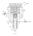
- FIG. 1 A prior art pump unit 1 is illustrated in Figure 1 .
- the pump unit 1 comprises a pump head 3 comprising a pumping chamber 5, an inlet valve 7 and an outlet valve 9.
- the pump head 3 is typically of "monoblock" construction meaning that it is formed in a single piece, for example as a one-piece forging.
- the inlet valve 7 comprises a movable inlet valve member 11, an inlet valve return spring 13, an inlet valve body 15 and an inlet valve plug 17.
- the inlet valve member 11 is movable between open and closed positions to control the supply of fuel to the pumping chamber 5 from a low pressure supply gallery 19.
- An inlet metering valve V IN is provided in communication with the low pressure supply gallery 19 to control the supply of fuel.
- the inlet valve 7 has two static seals; a first high pressure static seal provided on the inlet valve body 15, and a second low pressure static seal provided on the inlet valve plug 17.
- the high pressure static seal is exposed to a pressure that alternates between very low and very high levels for many millions of cycles. Due to differential radial expansion of the valve body 15 and the pump head 3 relative motion between the surface on each side of the seal interface can occur, even if this motion is extremely small (i.e. microns) fretting wear and failure can occur.
- the outlet valve 9 comprises a movable outlet valve member 21, an outlet valve return spring 23 and an outlet valve plug 25.
- the outlet valve 9 controls the supply of fuel from the pumping chamber 5 to a high pressure outlet gallery 27.
- the outlet valve 9 also has a high pressure static seal which may fail due to motion of the parts at the seal interface due to pressure fluctuation, potentially resulting in an external fuel leak.
- the static sealing surfaces of both the inlet valve 7 and the outlet valve 9 are difficult to machine because they are integral with the pump head 3, typically leading to higher processing costs.
- a plunger 29 is provided for pressurising fuel within the pumping chamber 5.
- the plunger 29 is movable axially in a barrel 31 formed in the pump head 3.
- the plunger 29 is typically driven by a cam (not shown) mounted on a rotatable cam shaft.
- a low pressure drain gallery 33 is provided for collecting fuel which escapes from the pumping chamber 5 around the outside of the plunger 29.
- fuel is supplied to the pumping chamber 5 from the low pressure supply gallery 19 via the inlet valve 7.
- the plunger 29 is retracted within the pumping chamber 5 causing fuel to be drawn from the supply gallery 19 into the pumping chamber 5.
- the pressure differential between the supply gallery 19 and the pumping chamber 5 ensures that the inlet valve member 11 is displaced to or remains in an open position.
- the plunger 29 is advanced into the pumping chamber 5 resulting in an increase in fuel pressure in the pumping chamber 5 which in turn permits the inlet valve member 9 to be displaced to a closed position in response to the action of the inlet return spring 11.
- the outlet valve 9 is connected to the pumping chamber 5 by an intersecting drilling (arranged at 90°).
- This geometry can result in increased operational stresses. So that stresses can be reduced, expensive machining processes may be required to radius the edges of the intersecting bore (for example, abrasive flow machining may be used since the restricted access may render conventional machining unsuitable).
- increased pressure specification for the pump unit may mean that it is not possible to keep stress sufficiently low with an intersecting geometry.
- the inlet valve spring 13 is contained inside the high pressure pumping chamber 5.
- this arrangement has the drawback that it is difficult to reduce the dead volume and this is likely to lead to reductions in volumetric and mechanical efficiency.
- the pump head 3 is a single component that contains high pressure static seals and plunger bores. As a result, a large number of processes must be undertaken on the pump head 3 with the potential for high scrap rate and scrap costs. Additionally, the material from which the pump head 3 is formed is very highly stressed in only a few small regions meaning that the vast majority of the volume of the pump head 3 (circa 90% or about 2 kilograms) is at low stress. The consequence is that a higher specification material must be used when for the majority of the pump head 3 a lower specification material would be sufficient.
- the barrel 31 can expand as the pressure in the pumping chamber 5 increases. This expansion can allow fuel to leak past the plunger 29 resulting in a reduction in efficiency of the pump unit 1. Any fuel that leaks around the plunger 29 is collected in the low pressure drain gallery 33.
- a pump unit 101 in accordance with a first embodiment of the present invention is shown schematically in Figure 2 .
- the pump unit 101 comprises a pump head 103, a pumping chamber 105, an inlet valve 107 and an outlet valve 109. It will be appreciated that a plurality of pumping chambers 105 can be formed in the pump head 103, but only one will be described herein for the sake of simplicity.
- the inlet valve 107 is provided to control the supply of fuel from a low pressure supply gallery 111 to the pumping chamber 105.
- the inlet valve 107 comprises an inlet valve member 113 which is located in a low pressure chamber 115 formed within the pump head 103.
- the low pressure chamber 115 has a diameter greater than that of the inlet valve member 113 such that the inlet valve 107 is in the form of a concentric valve.
- the inlet valve member 113 can be formed of a conventional material, such as steel.
- the inlet valve member 113 is formed from a material having a high Young's Modulus, for example cemented carbide.
- An inlet metering valve V IN is provided in communication with the low pressure supply gallery 111 to control the supply of fuel.
- the inlet valve member 113 is a one-piece sleeve partially closed at a first end, the interior of the sleeve defining the pumping chamber 105.
- An aperture 117 is provided at the first end of the inlet valve member 113.
- the interior of the inlet valve member 113 is open at a second end to receive a plunger 119 for pressurising fuel in the pumping chamber 105.
- a seal is formed between the plunger 119 and the inlet valve member 113 to seal the pumping chamber 105.
- the plunger 119 reciprocates within a barrel 121 formed in the pump head 103.
- the barrel 121 in the present embodiment is a bore formed in the pump head 103.
- a seal is formed between the plunger 119 and the barrel 121 in known manner. The skilled person will appreciate that the gap illustrated between the plunger 119 and the barrel 121 is to improve the clarity of the Figures and is not representative of the pump unit 101.
- the inlet valve member 113 is movable axially from a first position in which the inlet valve 107 is open (as shown in Figure 2 ) to a second position in which the inlet valve 107 is closed.
- An inlet valve return spring 123 is provided to bias the inlet valve member 113 to the second position in which the inlet valve 107 is closed.
- the outlet valve 109 controls the supply of pressurised fuel from the pumping chamber 105 to a high pressure manifold 125.
- the outlet valve 109 comprises an outlet valve body 127, an outlet valve member 129 and an outlet valve return spring 131.
- the outlet valve member 129 is movable axially to open and close the outlet valve 109.
- An annular projection 133 is formed on an upper face of the inlet valve member 113 around the aperture 117.
- the projection 133 could define a sharp edge for contacting the outlet valve body 127.
- the projection 133 defines a flat surface for contacting the outlet valve body 127 to form a seal.
- the projection 133 abuts the outlet valve body 127 when the inlet valve member 113 is in said second position to form a seal around the inlet to the outlet valve 109, thereby sealing the pumping chamber 105.
- more than one annular projection 133 can be provided.
- two annular projections 133 can be provided to form inner and outer seals.
- a low pressure drain gallery 135 is provided for collecting fuel which escapes from the pumping chamber 105 around the outside of the plunger 119. This leakage can occur as a result of expansion of the barrel 121 caused by pressurisation of the fuel within the pumping chamber 105.
- a drain flow restrictor D OUT is provided in fluid communication with the drain gallery 135 to increase the pressure of the leaked fuel upstream in the drain gallery 135.
- the fuel is supplied to the pump unit 101 through the low pressure supply gallery 111.
- the plunger 119 is retracted within the pumping chamber 5, reducing the pressure within the pumping chamber 105 and causing the inlet valve member 113 to move to its first position in which the inlet valve 107 is open. Fuel is drawn into the pumping chamber 105 from the low pressure supply gallery 111 during this phase.
- the plunger 119 is advanced, thereby reversing the direction of flow of fuel through the aperture 117 and causing a switch in the pressure differential between the pumping chamber 105 and the low pressure supply gallery 111.
- the change in pressure combined with the bias of the inlet return spring 123 causes the inlet valve member 113 to be displaced to its second position such that the projection 133 abuts the outlet valve body 127.
- the projection 133 forms a seal around the aperture 117 thereby closing the fluid pathway between the low pressure chamber 115 and the pumping chamber 105.
- the pumping chamber 105 is thereby sealed and the fuel in the pumping chamber 105 is pressurised by the continued advancement of the plunger 117, as shown in Figure 3C .
- the arrangement of the inlet valve member 113 allows the pumping chamber 105 and the inlet valve 107 to be combined into one component.
- this eliminates the high pressure static seal from the inlet valve assembly.
- the inlet valve return spring 123 can be moved from the pumping chamber 105 to the low pressure system and, at least in preferred embodiments, dead volume can be reduced and efficiency improved.
- the inlet valve member 113, the outlet valve member 129 and the plunger 119 are all movable co-axially in this embodiment. Moreover, the inlet to the outlet valve 109 and the aperture 117 in the inlet valve member 113 extend co-axially. Thus, the operational stresses of the pump unit 101 can be reduced and the manufacturing process simplified.
- a pump unit 201 according to a second embodiment of the present invention is shown in Figure 4 .
- the pump unit 201 comprises a pump head 203, a pumping chamber 205, an inlet valve 207 and an outlet valve 209.
- the fuel is supplied to the pumping chamber 205 from a low pressure inlet gallery 211 and is expelled from the pumping chamber 205 to a high pressure manifold 213.
- An inlet metering valve V IN is provided in communication with the low pressure supply gallery 211 to control the supply of fuel.
- a low pressure drain gallery 215 is provided to collect fuel that leaks from the pumping chamber 205.
- a drain flow restrictor D OUT can optionally be provided in fluid communication with the drain gallery 215 to pressurise the fuel upstream in the drain gallery 215.
- a plunger 217 is provided for pressurising fuel within the pumping chamber 205.
- the plunger 217 is movable axially within a barrel 219 located in the pump head 203 and a seal is formed between the plunger 217 and the barrel 219 in known manner.
- the barrel 219 in the present embodiment is a sleeve inserted into the pump head 203.
- the barrel 219 is made of a material having a higher Young's Modulus than the remainder of the material forming the pump head 203. This is advantageous since it can reduce leakage around the plunger 217.
- a suitable material for forming the barrel 219 is cemented carbide which has a Young's Modulus of 550MPa, approximately two and a half times that of steel. It will be appreciated that the sleeve forming the barrel 219 could be omitted such that the barrel 219 is formed directly in the pump head 203.
- the inlet valve 207 comprises an inlet valve member 221 for controlling the flow of fuel into the pumping chamber 205.
- the inlet valve member 221 is movable axially from a first position in which the inlet valve 207 is open (as shown in Figure 4 ) to a second position in which the inlet valve 207 is closed.
- the inlet valve member 221 comprises a cylindrical body portion 223 which locates sealingly in the barrel 219; and a head portion 225 positioned in a low pressure chamber 227 into which fuel is supplied from the inlet gallery 211.
- An aperture 229 extends axially through both the body portion 223 and the head portion 225 of the inlet valve member 221.
- the low pressure chamber 227 has a larger diameter than the head portion 225 of the inlet valve member 221 such that the inlet valve 207 takes the form of a concentric valve.
- the inlet valve member 221 When the inlet valve member 221 is in said first position, the inlet gallery 211 and the low pressure chamber 227 are in fluid communication with the pumping chamber 205 via the aperture 229 to allow fuel to enter the pumping chamber 105.
- the pumping chamber 205 When the inlet valve member 221 is in said second position, the pumping chamber 205 is in fluid communication exclusively with the outlet valve 209 via the aperture 229 to allow the fuel in the pumping chamber 105 to be pressurised.
- a return spring 231 is provided to bias the inlet valve member 221 to said second position.
- the outlet valve 209 is generally unchanged from that of the first embodiment of the present invention and comprises an outlet valve body 233, an outlet valve member 235 and an outlet return spring 237. As in the first embodiment, the outlet valve 209 controls the supply of pressurised fuel from the pumping chamber 205 to the high pressure manifold 213.
- the outlet valve member 235 is movable axially to open and close the outlet valve 209.
- An annular projection 239 is formed on an upper face of the inlet valve member 221 for abutting the outlet valve body 233 to form a seal around the inlet to the outlet valve 209.
- the projection 239 can thereby form a seal to separate the low pressure supply gallery 211 and the pumping chamber 205.
- the projection 239 could define a sharp edge for contacting the outlet valve body 233.
- the projection 239 defines a flat surface for contacting the outlet valve body. It will be appreciated that more than one projection 239 can be provided. For example, two projections 239 can be provided to define concentric surfaces forming inner and outer seals.
- the plunger 217 is retracted within the pumping chamber 205, reducing the pressure within the pumping chamber 205 and causing the inlet valve member 223 to move to said first position.
- the inlet valve 207 is thereby opened and fuel is drawn into the pumping chamber 205 from the low pressure supply gallery 211.
- the plunger 217 is advanced into the pumping chamber 205, as shown in Figure 5B , causing an increase in the pressure within the pumping chamber 205.
- the pressure differential switch between the pumping chamber 205 and the low pressure chamber 227 permits the inlet valve member 223 to be displaced to said second position, as shown in Figure 5C , in which the annular projection 239 abuts the outlet valve body 233, closing the inlet valve 207 and preventing fluid communication between the low pressure supply gallery 211 and the pumping chamber 205.
- the pumping chamber 205 is thereby sealed and the continued advancement of the plunger 217 pressurises the fuel within the pumping chamber 205.
- the second embodiment differs from the first embodiment in that the pumping chamber 205 and the inlet valve 207 are separate components. This offers the advantage that the inlet valve 207 can be made relatively small and its mass reduced to provide improved dynamic performance, at least in preferred embodiments.
- the concentric arrangement of the inlet valve 207 and the outlet valve 209 can also help to reduce stress loads as well as reducing the dead volume of the pump unit 201.
- a pump unit 201' which is a modified version of the pump unit 201 according to the second embodiment is illustrated in Figure 6 .
- like reference numerals have been used for like components.
- the pump unit 201' is provided with a piston ring 241 to help reduce leakage from the pumping chamber 205' to the low pressure drain gallery 215'.
- the piston ring 241 is located in a concentric recess 243 formed in the pump head 203' and is movable axially along the plunger 217'.
- the increased pressure within the pumping chamber 205' displaces the piston ring 241 downwardly (i.e. in the opposite direction to the direction of travel of the plunger 217') such that it seats on a bottom face 245 of the recess 243.
- the pressure of the fuel acting on the exterior of the piston ring 241 prevents the piston ring 241 from expanding and can cause it to contract around the plunger 217'. It will be appreciated, therefore, that a first seal is formed between the piston ring 241 and the bottom face 245 of the recess 243 and a second seal is formed between the plunger 217' and an internal surface of the piston ring 241.
- the piston ring 241 forms seals on two faces to seal the pumping chamber 205'.
- the piston ring 241 does not expand radially because it is exposed to the pumping pressure on all sides, unlike the conventional barrel 219 which is exposed to pressure only internally. Accordingly, the piston ring 241 does not expand radially when pressure is increased, so clearance between the ring 241 and the plunger 217' can be kept small and leakage reduced. Thus, the piston ring 241 can reduce or minimise leakage around the plunger 217'. This arrangement can help to minimise parasitic energy loss and improve system efficiency (fuel consumption), at least in preferred embodiments.
- the ring 241 could be developed to include an internal profile that improves the pressure balance and reduces radial compression. Additionally, the ring could be made of a higher Young's Modulus material to reduce the radial compression.
- a pump unit 201" " which is a further modified version of the pump unit 201 according to the second embodiment is illustrated in Figure 7 .
- like reference numerals have been used for like components.
- the pump unit 201 in this arrangement is modified such that the plunger 217 is replaced with a pushrod 249.
- a sleeve 251 is provided on the end of the pushrod 249 to form the pumping chamber 205".
- the body portion 223" of the inlet valve member 221" is slidably located within the sleeve 251 provided on the pushrod 249 to function as a plunger for pressurising fuel within the pumping.
- the inlet valve member 221" is movable between first and second positions to control the supply of fuel into and out of the pumping chamber 205".
- a first fluid pathway from the low pressure supply gallery 211" to the pumping chamber 205" is open.
- the inlet valve member 221" is in its second position, the first fluid pathway is closed and a second fluid pathway from the pumping chamber 205" to the outlet valve 209" is open.
- a return spring 231" is provided to bias the inlet valve member 223" towards the second position.
- the pushrod 249 is retracted, reducing the pressure within the pumping chamber 205" and causing the inlet valve member 221" to move to said first position.
- the inlet valve 207" is thereby opened and fuel is drawn into the pumping chamber 205 from the low pressure supply gallery 211 ".
- the pushrod 249 is advanced causing the body portion 223" of the inlet valve member 221" to be introduced into the sleeve 251. This results in an increase in the pressure of the fuel within the pumping chamber 205".
- the pressure differential switch between the pumping chamber 205" and the low pressure chamber 227” permits the inlet valve member 221" to be displaced to said second position.
- the annular projection 239" formed on the head portion 225" of the inlet valve member 221" thereby abuts the outlet valve body 233" and the inlet valve 207" is closed, sealing the pumping chamber 205" and preventing fluid communication with the low pressure supply gallery 211 ".
- the continued advancement of the pushrod 249 pressurises the fuel within the sealed pumping chamber 205".
- a pump unit 301 in accordance with a third embodiment of the present invention will now be described with reference to Figure 8 .
- the pump unit 301 comprises a pump head 303, a pumping chamber 305, an inlet valve 307 and an outlet valve 309.
- the inlet valve 307 comprises a piston ring 311 and a piston ring return spring 313, both located in an annular recess 315 formed in the pump head 303.
- a supply of fuel is provided from a low pressure supply gallery 317 into a first annular chamber 319 provided around a plunger 321.
- the first annular chamber 319 is open to a first side of the piston ring 311.
- a low pressure drain gallery 323 is connected to a second annular chamber 325 also extending around the plunger 321.
- the first and second annular chambers 319, 325 are separated from each other by an annular flange 327 which sealingly engages the piston 321 about its circumference.
- the pumping chamber 305 has a diameter larger than that of the plunger 321 to allow fuel to enter the pumping chamber 305 around the plunger 321.
- An inlet metering valve V IN is provided in communication with the low pressure supply gallery 317 to control the supply of fuel.
- a drain flow restrictor D OUT is provided in fluid communication with the drain gallery 323 to increase the fuel pressure upstream in the drain gallery 323.
- the piston ring 311 is movable between a lifted position and a seated position abutting a bottom face 329 of the annular recess 315 (as shown in Figure 7 ). With the piston ring 311 in said lifted position, the low pressure supply gallery 317 is in fluid communication with the pumping chamber 305 and, therefore, the inlet valve 307 is open. With the piston ring 311 in said seated position, the pumping chamber 305 is sealed and, therefore, the inlet valve 307 is closed.
- the outlet valve 309 is generally unchanged from the previous embodiments described herein and comprises an outlet valve body 331, an outlet valve member 333 and an outlet return spring 335.
- the outlet valve 309 controls the flow of fuel from the pumping chamber 305 to a high pressure manifold 337.
- the plunger 321 is retracted within the pumping chamber 305 thereby reducing the pressure within the pumping chamber 305.
- the piston ring 311 lifts from the bottom face 329 of the annular recess 315 and opens the inlet valve 307 to allow fuel to enter the pumping chamber 305.
- the plunger 321 is advanced into the pumping chamber 305 causing an increase in the pressure within the pumping chamber 305 which in turn causes the piston ring 311 to return to its seated position abutting the bottom face 329 of the annular recess 315 and closing the inlet valve 307.
- the pumping chamber 305 is thereby sealed and the continued motion of the plunger 321 increases the pressure within the pumping chamber 305 until it is higher than that in the high pressure manifold 337.
- the outlet valve member 333 is then unseated against the action of the outlet return spring 335 and the outlet valve 309 opens to allow pressurised fuel to be discharged from the pumping chamber 305 into the high pressure manifold 337.
- the pump unit 301 according to the third embodiment of the present invention advantageously uses the piston ring 311 to provide a seal around the plunger 321 to reduce leakage and also to act as an inlet valve 307.
- the number of components in the pump unit 301 can be reduced.
- a modified pump unit 1' is illustrated in Figure 9 and like reference numerals have been used for like components.
- a cemented carbide sleeve 33 is fixedly mounted in the pump head 3' to receive the plunger 29'.
- the sleeve 33 is less subjectable to expansion due to the increased pressures within the pump chamber 5 and, therefore, the leakage of fuel around the plunger 29' is reduced.
- the operation of the pump unit 1' remains unchanged from that described previously herein.
- a plurality of pumping units 1'; 101; 201, 201'; 201 "; 301 described herein could be arranged in an array of two or more in order to increase the capacity of the pump.
- the plunger in the various embodiments described herein can be driven by a cam shaft or other suitable mechanical or electromechanical drive means.
Abstract
Description
- The present application relates to a pump unit. More particularly, the present application relates to a pump unit for a fuel injection system for an internal combustion engine.
- There is an increasing need for improved efficiency of internal combustion engines. In order to meet these needs and to comply with new emissions legislation, the operating pressure of diesel engines continues to increase and operating pressures of 3000 bar (300MPa) are envisaged. However, these increased operating pressures present a variety of technical problems.
- It is known to provide a fuel injection pump unit comprising a plunger operating within a barrel to raise fuel pressure before discharging the pressurised fuel to a high pressure manifold. However, known pump units are generally unsuitable for operating at the increased pressures now required. A prior art pump unit of this type is illustrated in
Figure 1 and described in detail below. - Known pump units typically rely on a combination of static and dynamic seals to seal the pumping chamber. However, due to the alternating pressure cycles encountered within the pump unit, even small inaccuracies in the manufacturing process may cause a seal to fail. For example, a high pressure static seal is typically provided to separate the low pressure supply gallery and the pressure chamber. The seal encounters cyclical pressure changes from very low to very high and, as a result of differential radial expansion, relative motion may be induced between the surfaces on each side of the seal interface. Even if the resulting motion is very small, fretting wear and failure may result.
- Furthermore, the internal geometry of known pump units may include intersecting bores and these may result in high stresses being induced during operation. To ensure safe and reliable operation, the pump head may have to be formed from higher specification materials or specialised manufacturing processes used to reduce the operational stresses.
- A further problem exacerbated by operating at high pressures is increased fuel leakage which may result in higher fuel consumption. The high pressures generated within the pumping chamber may result in radial expansion of the barrel. As there is no corresponding expansion of the plunger, fuel leakage past the plunger may result.
- The present invention(s) at least in preferred embodiments attempts to overcome or ameliorate at least some of the problems associated with known pump units.
- Viewed from a first aspect, the present application relates to a pump unit for a fuel injection system, the pump unit comprising:
- an inlet sealing ring, a pumping chamber and a plunger for pressurising fuel in the pumping chamber;
- the inlet sealing ring being movably mounted on the plunger;
- In use, the inlet sealing ring is preferably movable in response to changes in fluid pressures within the pumping chamber. The inlet sealing ring is preferably movable axially within a recess extending around the plunger. The recess is preferably annular. The recess can, for example, be formed in a pump head defining the pumping chamber.
- Preferably, when in said second position, the inlet sealing ring abuts a face or an end wall of the annular recess to form a seal thereby closing the fluid pathway between the pumping chamber and the supply line.
- Viewed from a further aspect, the present application relates to a pump unit for a fuel injection system, the pump unit comprising:
- an inlet valve member, an outlet valve, a supply line for supplying fuel, a pumping chamber, and a plunger for pressurising fuel in the pumping chamber;
- the inlet valve member being movable between a first position and a second position;
- At least in preferred embodiments, this arrangement can obviate the need to provide separate static and dynamic seals. Preferably, the inlet valve member can provide a fluid pathway directly from the supply line to the pumping chamber thereby removing the need to provide a static seal between the pumping chamber and the supply line.
- When the inlet valve member is in said first position, the first fluid pathway between the supply line and the pumping chamber is open so that fuel can enter the pumping chamber. Once fuel has entered the pumping chamber, the inlet valve member can be displaced to said second position to place an interior of the pumping chamber in fluid communication with the outlet valve. When the inlet valve member is in said second position, the first fluid pathway between the supply line and the pumping chamber is preferably at least substantially closed. Most preferably, the inlet valve member forms a seal at least substantially to close the first fluid pathway when the inlet valve member is in said second position. Thus, the pumping chamber preferably communicates exclusively with the outlet valve when the inlet valve member is in said second position.
- The inlet valve member preferably forms a seal with a body of the outlet valve when it is in said second position. This arrangement is advantageous since it means that a seal can be formed distal from the head of the plunger. Thus, unlike prior art arrangements in which high pressure fuel is sealed at the head of the plunger, it is not necessary for static sealing against the head.
- In use, the fluid in the pumping chamber is pressurised by the plunger. The plunger is preferably driven by a cam or other suitable drive means. The movement of the inlet valve member between said first and second positions is preferably controlled by the pressure of the fluid within the pumping chamber. An inlet valve return spring can be provided to return the inlet valve member to either said first position or said second position. The outlet valve preferably controls the flow of pressurised fluid from the pumping chamber to a high pressure outlet line or manifold.
- The inlet valve member preferably forms part of an inlet valve. The inlet valve is preferably a concentric valve. The outlet valve is preferably a concentric valve. The inlet valve and the outlet valve can both be concentric valves to reduce the stress in the pump unit.
- Preferably, the outlet valve comprises a movable outlet valve member. The outlet valve member is preferably biased to a closed position by an outlet valve return spring. Preferably, the inlet valve member and the outlet valve member are movable in the same direction. The inlet valve member and the outlet valve member are preferably arranged to undergo displacement along substantially parallel axes or, more preferably, along a common axis.
- The plunger preferably travels in a barrel. A seal is preferably created between the plunger and the barrel for reducing or preventing fuel leakage between the barrel and the plunger when the fuel is pressurised. Preferably, a drain outlet is provided for collecting any leaked fuel.
- The pump unit preferably comprises a pump head made of a first material. An insert is preferably provided in the pump head to define a sidewall of the pumping chamber. The insert is preferably in the form of a sleeve to define a barrel in which the plunger travels. The insert can be made of a second material having a higher Young's Modulus (E) than the first material. This arrangement can reduce leakage around the plunger when the pumping chamber is pressurised.
- The pump unit can further comprise a pushrod having a sleeve or bore for forming the pumping chamber. In this arrangement a body portion of the inlet valve member can extend into the sleeve or bore to function as the plunger for pressurising fuel
- In preferred embodiments, a chamber or recess can be formed in the inlet valve member to define said pumping chamber. In use, an end of said plunger can operably extend into said pumping chamber. In use, a seal is preferably formed between said plunger and the inlet valve member to seal the pumping chamber.
- A sealing ring can be movably mounted on the plunger. The sealing ring can provide a dynamic seal to help reduce or minimise leakage past the plunger. The sealing ring is preferably movable axially within a recess formed in the pump head around the plunger. The recess is preferably annular. The sealing ring can take the form of a piston ring.
- Viewed from a yet further aspect, the present application relates to a pump unit for a fuel injection system, the pump unit comprising: an inlet valve comprising an inlet valve member, and an outlet valve comprising an outlet valve member; wherein the inlet valve member and the outlet valve member are movable along a common axis. At least in preferred embodiments, the co-axial arrangement of the inlet and outlet valves is inherently stronger than prior art arrangements.
- Viewed from a still further aspect, the present application relates to a pump unit for a fuel injection system, the pump unit comprising: an inlet valve, an outlet valve and a plunger movably mounted in a pumping chamber; the outlet valve comprising an outlet valve member; wherein the plunger and the outlet valve member are movable along a common axis or along substantially parallel axes.
- The inlet valve preferably comprises an inlet valve member. The inlet valve member is preferably movable along an axis which is substantially parallel to or substantially coincident with the axis along which the plunger and the outlet valve member are movable.
- Viewed from a yet still further aspect, the present application relates to a pump unit for a fuel injection system, the pump unit comprising: an inlet valve member, an outlet valve, a supply line for supplying fuel, and a pushrod; the inlet valve member being movable between a first position and a second position; wherein a chamber is formed in the pushrod to define a pumping chamber, the pumping chamber being in fluid communication with the supply line when the inlet valve member is in said first position, and the pumping chamber being in fluid communication with the outlet valve when the inlet valve member is in said second position. In use, a portion of the inlet valve member preferably extends into the pumping chamber to function as a plunger.
- Viewed from a further aspect, the present application relates to a pump unit for a fuel injection system, the pump unit comprising: an inlet valve for controlling the supply of fuel from a supply line to a pumping chamber, and an outlet valve for controlling the supply of pressurised fuel from the pumping chamber to a high pressure outlet line; wherein the inlet valve is a concentric valve and/or the outlet valve is a concentric valve.
- As outlined above, a further problem associated with current pumping systems is that the increased operating pressures ahead of the plunger cause the barrel to expand, thereby increasing the clearance between the plunger and the barrel. This causes the fuel leakage rate to increase and consequently increases parasitic power loss and fuel consumption.
- Viewed from a yet further aspect, the present application relates to a pump head for a fuel injection pump, wherein a pumping chamber is formed in said pump head and an insert is provided to define at least a portion of a sidewall of the pumping chamber, the pump head being made of a first material and the insert being made of a second material, wherein the second material has a higher Young's Modulus than the first material. This arrangement is believed to be patentable independently of the other invention(s) described herein. The insert is typically a sleeve or a barrel in which a plunger reciprocates. Advantageously, by forming the insert from a material having a higher Young's Modulus, the expansion of the insert can be reduced. A suitable material for forming the insert is cemented carbide which has a Young's Modulus of approximately 550MPa. By providing an insert having the desired properties, a modular design can be implemented in which the remainder of the pump head can be formed from a lower specification material.
- Furthermore, the skilled person will understand that the arrangement of providing an insert having a higher Young's Modulus than the surrounding material is suitable for other applications, particularly in hydraulic systems. Viewed from a further aspect, the present application relates to a hydraulic system comprising a body portion, wherein a chamber is provided in said body portion for receiving a movable member, an insert being provided in the body portion to define at least a portion of a sidewall of the chamber, the body portion being made of a first material and the insert being made of a second material, wherein the second material has a higher Young's Modulus than the first material. In use, the movable member preferably cooperates with the insert to form a seal. The hydraulic system can be, for example, a control valve or an injector nozzle. The body portion can be a housing or casing for the hydraulic system.
- It will be appreciated that the supply line for supplying fuel to a pump unit as described herein can be a supply gallery for supplying fuel to one or more pump units. Similarly, the outlet line can be an outlet manifold for connecting one or more pump units as described herein.
- Preferred embodiments of the present invention(s) will now be described, by way of example only, with reference to the accompanying drawings, in which:
-
Figure 1 shows schematically a prior art pump unit; -
Figure 2 shows a first embodiment of a pump unit in accordance with the present invention; -
Figures 3A to 3D illustrate the different steps in the operational cycle of the pump unit according to the first embodiment; -
Figure 4 shows a second embodiment of a pump unit in accordance with the present invention; -
Figures 5A to 5D illustrate the different steps in the operational cycle of the pump unit according to the second embodiment; -
Figure 6 shows a first modified version of the second embodiment of the present invention; -
Figure 7 shows a second modified version of the second embodiment of the present invention; -
Figure 8 shows a pump unit in accordance with a third embodiment of the present invention; and -
Figure 9 shows a pump unit having a sleeve inserted in the pump head to define the barrel in which the plunger travels. - A prior art pump unit 1 is illustrated in
Figure 1 . The pump unit 1 comprises a pump head 3 comprising apumping chamber 5, aninlet valve 7 and an outlet valve 9. The pump head 3 is typically of "monoblock" construction meaning that it is formed in a single piece, for example as a one-piece forging. - The
inlet valve 7 comprises a movableinlet valve member 11, an inletvalve return spring 13, aninlet valve body 15 and aninlet valve plug 17. Theinlet valve member 11 is movable between open and closed positions to control the supply of fuel to thepumping chamber 5 from a lowpressure supply gallery 19. An inlet metering valve VIN is provided in communication with the lowpressure supply gallery 19 to control the supply of fuel. - The
inlet valve 7 has two static seals; a first high pressure static seal provided on theinlet valve body 15, and a second low pressure static seal provided on theinlet valve plug 17. The high pressure static seal is exposed to a pressure that alternates between very low and very high levels for many millions of cycles. Due to differential radial expansion of thevalve body 15 and the pump head 3 relative motion between the surface on each side of the seal interface can occur, even if this motion is extremely small (i.e. microns) fretting wear and failure can occur. - The outlet valve 9 comprises a movable
outlet valve member 21, an outletvalve return spring 23 and anoutlet valve plug 25. The outlet valve 9 controls the supply of fuel from thepumping chamber 5 to a highpressure outlet gallery 27. The outlet valve 9 also has a high pressure static seal which may fail due to motion of the parts at the seal interface due to pressure fluctuation, potentially resulting in an external fuel leak. The static sealing surfaces of both theinlet valve 7 and the outlet valve 9 are difficult to machine because they are integral with the pump head 3, typically leading to higher processing costs. - A
plunger 29 is provided for pressurising fuel within thepumping chamber 5. Theplunger 29 is movable axially in abarrel 31 formed in the pump head 3. Theplunger 29 is typically driven by a cam (not shown) mounted on a rotatable cam shaft. A lowpressure drain gallery 33 is provided for collecting fuel which escapes from thepumping chamber 5 around the outside of theplunger 29. - In use, fuel is supplied to the
pumping chamber 5 from the lowpressure supply gallery 19 via theinlet valve 7. During a first phase, theplunger 29 is retracted within thepumping chamber 5 causing fuel to be drawn from thesupply gallery 19 into thepumping chamber 5. The pressure differential between thesupply gallery 19 and thepumping chamber 5 ensures that theinlet valve member 11 is displaced to or remains in an open position. In the next phase, theplunger 29 is advanced into thepumping chamber 5 resulting in an increase in fuel pressure in thepumping chamber 5 which in turn permits the inlet valve member 9 to be displaced to a closed position in response to the action of theinlet return spring 11. The continued advancement of theplunger 29 increases the pressure within thepumping chamber 5 further and, once the pressure is greater than that within the highpressure outlet gallery 27, theoutlet valve member 21 is displaced to an open position allowing pressurised fuel to exit thepumping chamber 5 through the highpressure outlet gallery 27. These steps are then repeated in sequence in each pump cycle. - The outlet valve 9 is connected to the
pumping chamber 5 by an intersecting drilling (arranged at 90°). However, this geometry can result in increased operational stresses. So that stresses can be reduced, expensive machining processes may be required to radius the edges of the intersecting bore (for example, abrasive flow machining may be used since the restricted access may render conventional machining unsuitable). Moreover, increased pressure specification for the pump unit may mean that it is not possible to keep stress sufficiently low with an intersecting geometry. - The
inlet valve spring 13 is contained inside the highpressure pumping chamber 5. However, this arrangement has the drawback that it is difficult to reduce the dead volume and this is likely to lead to reductions in volumetric and mechanical efficiency. - It will be appreciated that the pump head 3 is a single component that contains high pressure static seals and plunger bores. As a result, a large number of processes must be undertaken on the pump head 3 with the potential for high scrap rate and scrap costs. Additionally, the material from which the pump head 3 is formed is very highly stressed in only a few small regions meaning that the vast majority of the volume of the pump head 3 (circa 90% or about 2 kilograms) is at low stress. The consequence is that a higher specification material must be used when for the majority of the pump head 3 a lower specification material would be sufficient.
- Furthermore, in use, the
barrel 31 can expand as the pressure in thepumping chamber 5 increases. This expansion can allow fuel to leak past theplunger 29 resulting in a reduction in efficiency of the pump unit 1. Any fuel that leaks around theplunger 29 is collected in the lowpressure drain gallery 33. - A
pump unit 101 in accordance with a first embodiment of the present invention is shown schematically inFigure 2 . Thepump unit 101 comprises apump head 103, apumping chamber 105, aninlet valve 107 and anoutlet valve 109. It will be appreciated that a plurality of pumpingchambers 105 can be formed in thepump head 103, but only one will be described herein for the sake of simplicity. - The
inlet valve 107 is provided to control the supply of fuel from a lowpressure supply gallery 111 to thepumping chamber 105. Theinlet valve 107 comprises aninlet valve member 113 which is located in alow pressure chamber 115 formed within thepump head 103. Thelow pressure chamber 115 has a diameter greater than that of theinlet valve member 113 such that theinlet valve 107 is in the form of a concentric valve. Theinlet valve member 113 can be formed of a conventional material, such as steel. Preferably, however, theinlet valve member 113 is formed from a material having a high Young's Modulus, for example cemented carbide. - An inlet metering valve VIN is provided in communication with the low
pressure supply gallery 111 to control the supply of fuel. - The
inlet valve member 113 is a one-piece sleeve partially closed at a first end, the interior of the sleeve defining thepumping chamber 105. Anaperture 117 is provided at the first end of theinlet valve member 113. The interior of theinlet valve member 113 is open at a second end to receive aplunger 119 for pressurising fuel in thepumping chamber 105. A seal is formed between theplunger 119 and theinlet valve member 113 to seal thepumping chamber 105. - The
plunger 119 reciprocates within abarrel 121 formed in thepump head 103. Thebarrel 121 in the present embodiment is a bore formed in thepump head 103. A seal is formed between theplunger 119 and thebarrel 121 in known manner. The skilled person will appreciate that the gap illustrated between theplunger 119 and thebarrel 121 is to improve the clarity of the Figures and is not representative of thepump unit 101. - The
inlet valve member 113 is movable axially from a first position in which theinlet valve 107 is open (as shown inFigure 2 ) to a second position in which theinlet valve 107 is closed. An inletvalve return spring 123 is provided to bias theinlet valve member 113 to the second position in which theinlet valve 107 is closed. When theinlet valve member 113 is in said first position, theinlet gallery 111 and thelow pressure chamber 115 are in fluid communication with thepumping chamber 105 via theaperture 117 to allow fuel to enter thepumping chamber 105. When theinlet valve member 221 is in said second position, thepumping chamber 105 is in fluid communication exclusively with theoutlet valve 109 via theaperture 117 to allow the fuel in thepumping chamber 105 to be pressurised. - The
outlet valve 109 controls the supply of pressurised fuel from thepumping chamber 105 to ahigh pressure manifold 125. Theoutlet valve 109 comprises anoutlet valve body 127, anoutlet valve member 129 and an outletvalve return spring 131. Theoutlet valve member 129 is movable axially to open and close theoutlet valve 109. - An
annular projection 133 is formed on an upper face of theinlet valve member 113 around theaperture 117. Theprojection 133 could define a sharp edge for contacting theoutlet valve body 127. Preferably, however, theprojection 133 defines a flat surface for contacting theoutlet valve body 127 to form a seal. Theprojection 133 abuts theoutlet valve body 127 when theinlet valve member 113 is in said second position to form a seal around the inlet to theoutlet valve 109, thereby sealing thepumping chamber 105. It will be appreciated that more than oneannular projection 133 can be provided. For example, twoannular projections 133 can be provided to form inner and outer seals. - A low
pressure drain gallery 135 is provided for collecting fuel which escapes from thepumping chamber 105 around the outside of theplunger 119. This leakage can occur as a result of expansion of thebarrel 121 caused by pressurisation of the fuel within thepumping chamber 105. A drain flow restrictor DOUT is provided in fluid communication with thedrain gallery 135 to increase the pressure of the leaked fuel upstream in thedrain gallery 135. - The operation of the
pump unit 101 will now be described with reference toFigures 3A to 3D . - The fuel is supplied to the
pump unit 101 through the lowpressure supply gallery 111. As illustrated inFigure 3A , during a first phase, theplunger 119 is retracted within thepumping chamber 5, reducing the pressure within thepumping chamber 105 and causing theinlet valve member 113 to move to its first position in which theinlet valve 107 is open. Fuel is drawn into thepumping chamber 105 from the lowpressure supply gallery 111 during this phase. - As illustrated in
Figure 3B , during a second phase theplunger 119 is advanced, thereby reversing the direction of flow of fuel through theaperture 117 and causing a switch in the pressure differential between the pumpingchamber 105 and the lowpressure supply gallery 111. The change in pressure combined with the bias of theinlet return spring 123 causes theinlet valve member 113 to be displaced to its second position such that theprojection 133 abuts theoutlet valve body 127. Theprojection 133 forms a seal around theaperture 117 thereby closing the fluid pathway between thelow pressure chamber 115 and thepumping chamber 105. Thepumping chamber 105 is thereby sealed and the fuel in thepumping chamber 105 is pressurised by the continued advancement of theplunger 117, as shown inFigure 3C . - When the pressure in the
pumping chamber 105 exceeds the pressure in thehigh pressure manifold 125, theoutlet valve member 129 is unseated from theoutlet valve body 127, against the action of the outletvalve return spring 131, and theoutlet valve 109 is opened thereby allowing pressurised fuel to be discharged from thepumping chamber 105 to thehigh pressure manifold 125. - It will be appreciated that the arrangement of the
inlet valve member 113 according to this embodiment allows thepumping chamber 105 and theinlet valve 107 to be combined into one component. Advantageously, this eliminates the high pressure static seal from the inlet valve assembly. Moreover, the inletvalve return spring 123 can be moved from thepumping chamber 105 to the low pressure system and, at least in preferred embodiments, dead volume can be reduced and efficiency improved. - The
inlet valve member 113, theoutlet valve member 129 and theplunger 119 are all movable co-axially in this embodiment. Moreover, the inlet to theoutlet valve 109 and theaperture 117 in theinlet valve member 113 extend co-axially. Thus, the operational stresses of thepump unit 101 can be reduced and the manufacturing process simplified. - A
pump unit 201 according to a second embodiment of the present invention is shown inFigure 4 . Thepump unit 201 comprises apump head 203, apumping chamber 205, aninlet valve 207 and anoutlet valve 209. The fuel is supplied to thepumping chamber 205 from a lowpressure inlet gallery 211 and is expelled from thepumping chamber 205 to ahigh pressure manifold 213. - An inlet metering valve VIN is provided in communication with the low
pressure supply gallery 211 to control the supply of fuel. A lowpressure drain gallery 215 is provided to collect fuel that leaks from thepumping chamber 205. A drain flow restrictor DOUT can optionally be provided in fluid communication with thedrain gallery 215 to pressurise the fuel upstream in thedrain gallery 215. - A
plunger 217 is provided for pressurising fuel within thepumping chamber 205. Theplunger 217 is movable axially within abarrel 219 located in thepump head 203 and a seal is formed between theplunger 217 and thebarrel 219 in known manner. Thebarrel 219 in the present embodiment is a sleeve inserted into thepump head 203. Thebarrel 219 is made of a material having a higher Young's Modulus than the remainder of the material forming thepump head 203. This is advantageous since it can reduce leakage around theplunger 217. A suitable material for forming thebarrel 219 is cemented carbide which has a Young's Modulus of 550MPa, approximately two and a half times that of steel. It will be appreciated that the sleeve forming thebarrel 219 could be omitted such that thebarrel 219 is formed directly in thepump head 203. - The
inlet valve 207 comprises aninlet valve member 221 for controlling the flow of fuel into thepumping chamber 205. Theinlet valve member 221 is movable axially from a first position in which theinlet valve 207 is open (as shown inFigure 4 ) to a second position in which theinlet valve 207 is closed. Theinlet valve member 221 comprises acylindrical body portion 223 which locates sealingly in thebarrel 219; and ahead portion 225 positioned in alow pressure chamber 227 into which fuel is supplied from theinlet gallery 211. Anaperture 229 extends axially through both thebody portion 223 and thehead portion 225 of theinlet valve member 221. Thelow pressure chamber 227 has a larger diameter than thehead portion 225 of theinlet valve member 221 such that theinlet valve 207 takes the form of a concentric valve. - When the
inlet valve member 221 is in said first position, theinlet gallery 211 and thelow pressure chamber 227 are in fluid communication with thepumping chamber 205 via theaperture 229 to allow fuel to enter thepumping chamber 105. When theinlet valve member 221 is in said second position, thepumping chamber 205 is in fluid communication exclusively with theoutlet valve 209 via theaperture 229 to allow the fuel in thepumping chamber 105 to be pressurised. Areturn spring 231 is provided to bias theinlet valve member 221 to said second position. - The
outlet valve 209 is generally unchanged from that of the first embodiment of the present invention and comprises anoutlet valve body 233, anoutlet valve member 235 and anoutlet return spring 237. As in the first embodiment, theoutlet valve 209 controls the supply of pressurised fuel from thepumping chamber 205 to thehigh pressure manifold 213. Theoutlet valve member 235 is movable axially to open and close theoutlet valve 209. - An
annular projection 239 is formed on an upper face of theinlet valve member 221 for abutting theoutlet valve body 233 to form a seal around the inlet to theoutlet valve 209. Theprojection 239 can thereby form a seal to separate the lowpressure supply gallery 211 and thepumping chamber 205. Theprojection 239 could define a sharp edge for contacting theoutlet valve body 233. Preferably, however, theprojection 239 defines a flat surface for contacting the outlet valve body. It will be appreciated that more than oneprojection 239 can be provided. For example, twoprojections 239 can be provided to define concentric surfaces forming inner and outer seals. - The operation of the
pump unit 201 in accordance with the second embodiment of the present invention will now be described with reference toFigures 5A to 5D . - As shown in
Figure 5A , during a first phase, theplunger 217 is retracted within thepumping chamber 205, reducing the pressure within thepumping chamber 205 and causing theinlet valve member 223 to move to said first position. Theinlet valve 207 is thereby opened and fuel is drawn into thepumping chamber 205 from the lowpressure supply gallery 211. - During a second phase, the
plunger 217 is advanced into thepumping chamber 205, as shown inFigure 5B , causing an increase in the pressure within thepumping chamber 205. The pressure differential switch between the pumpingchamber 205 and thelow pressure chamber 227 permits theinlet valve member 223 to be displaced to said second position, as shown inFigure 5C , in which theannular projection 239 abuts theoutlet valve body 233, closing theinlet valve 207 and preventing fluid communication between the lowpressure supply gallery 211 and thepumping chamber 205. Thepumping chamber 205 is thereby sealed and the continued advancement of theplunger 217 pressurises the fuel within thepumping chamber 205. Once the pressure of the fuel in thepumping chamber 205 exceeds the pressure in thehigh pressure manifold 213, theoutlet valve 209 is opened against the action of theoutlet return spring 237 and pressurised fuel exits thepumping chamber 205 to thehigh pressure manifold 213, as shown inFigure 5D . - The second embodiment differs from the first embodiment in that the
pumping chamber 205 and theinlet valve 207 are separate components. This offers the advantage that theinlet valve 207 can be made relatively small and its mass reduced to provide improved dynamic performance, at least in preferred embodiments. The concentric arrangement of theinlet valve 207 and theoutlet valve 209 can also help to reduce stress loads as well as reducing the dead volume of thepump unit 201. - Due to expansion of the
barrel 219 when theplunger 217 is advanced, fuel within thepumping chamber 205 can escape past theplunger 217. This leakage is collected in the lowpressure drain gallery 215. - A pump unit 201' which is a modified version of the
pump unit 201 according to the second embodiment is illustrated inFigure 6 . For the sake of brevity, like reference numerals have been used for like components. - The pump unit 201' is provided with a
piston ring 241 to help reduce leakage from the pumping chamber 205' to the low pressure drain gallery 215'. Thepiston ring 241 is located in aconcentric recess 243 formed in the pump head 203' and is movable axially along the plunger 217'. - As the plunger 217' advances, the increased pressure within the pumping chamber 205' displaces the
piston ring 241 downwardly (i.e. in the opposite direction to the direction of travel of the plunger 217') such that it seats on abottom face 245 of therecess 243. The pressure of the fuel acting on the exterior of thepiston ring 241 prevents thepiston ring 241 from expanding and can cause it to contract around the plunger 217'. It will be appreciated, therefore, that a first seal is formed between thepiston ring 241 and thebottom face 245 of therecess 243 and a second seal is formed between the plunger 217' and an internal surface of thepiston ring 241. Thus, thepiston ring 241 forms seals on two faces to seal the pumping chamber 205'. - In use, the
piston ring 241 does not expand radially because it is exposed to the pumping pressure on all sides, unlike theconventional barrel 219 which is exposed to pressure only internally. Accordingly, thepiston ring 241 does not expand radially when pressure is increased, so clearance between thering 241 and the plunger 217' can be kept small and leakage reduced. Thus, thepiston ring 241 can reduce or minimise leakage around the plunger 217'. This arrangement can help to minimise parasitic energy loss and improve system efficiency (fuel consumption), at least in preferred embodiments. - It is envisaged that it may prove difficult to control the pressure gradient applied by the
piston ring 241. In particular, as the pressure on the inside of thepiston ring 241 is decreasing from the high pressure side to the low pressure side, there will be a pressure gradient established. This means that the pressure may not be completely equal from the inside to the outside and it is possible that thepiston 241 will compress radially and grip the plunger 217'. This may be undesirable for reasons of durability and efficiency (due to increased friction). To help address this issue, the ring could be developed to include an internal profile that improves the pressure balance and reduces radial compression. Additionally, the ring could be made of a higher Young's Modulus material to reduce the radial compression. - A
pump unit 201" " which is a further modified version of thepump unit 201 according to the second embodiment is illustrated inFigure 7 . For the sake of brevity, like reference numerals have been used for like components. - The
pump unit 201 in this arrangement is modified such that theplunger 217 is replaced with apushrod 249. Asleeve 251 is provided on the end of thepushrod 249 to form thepumping chamber 205". Thebody portion 223" of theinlet valve member 221" is slidably located within thesleeve 251 provided on thepushrod 249 to function as a plunger for pressurising fuel within the pumping. - As in the previous embodiments, the
inlet valve member 221" is movable between first and second positions to control the supply of fuel into and out of thepumping chamber 205". When theinlet valve member 221" is in its first position, a first fluid pathway from the lowpressure supply gallery 211" to thepumping chamber 205" is open. When theinlet valve member 221" is in its second position, the first fluid pathway is closed and a second fluid pathway from thepumping chamber 205" to theoutlet valve 209" is open. Thus, when theinlet valve member 221" is in said second position, thepumping chamber 205" communicates exclusively with theoutlet valve 209" via theaperture 225". Areturn spring 231" is provided to bias theinlet valve member 223" towards the second position. The operation of thepump unit 201" will now be described. - During a first phase, the
pushrod 249 is retracted, reducing the pressure within thepumping chamber 205" and causing theinlet valve member 221" to move to said first position. Theinlet valve 207" is thereby opened and fuel is drawn into thepumping chamber 205 from the lowpressure supply gallery 211 ". - During a second phase, the
pushrod 249 is advanced causing thebody portion 223" of theinlet valve member 221" to be introduced into thesleeve 251. This results in an increase in the pressure of the fuel within thepumping chamber 205". The pressure differential switch between the pumpingchamber 205" and thelow pressure chamber 227" permits theinlet valve member 221" to be displaced to said second position. Theannular projection 239" formed on thehead portion 225" of theinlet valve member 221" thereby abuts theoutlet valve body 233" and theinlet valve 207" is closed, sealing thepumping chamber 205" and preventing fluid communication with the lowpressure supply gallery 211 ". The continued advancement of thepushrod 249 pressurises the fuel within the sealedpumping chamber 205". Once the pressure of the fuel in thepumping chamber 205" exceeds the pressure in thehigh pressure manifold 213", theoutlet valve 209" is opened and pressurised fuel exits thepumping chamber 205", through theaperture 229" and theoutlet valve 209", to thehigh pressure manifold 213". - This modified arrangement allows the size of the
inlet valve 209" to be reduced. However, it will be appreciated that theinlet valve member 221" needs to be sufficiently long to stay engaged in thesleeve 251 as thepushrod 249 is retracted. - A
pump unit 301 in accordance with a third embodiment of the present invention will now be described with reference toFigure 8 . - The
pump unit 301 comprises apump head 303, apumping chamber 305, aninlet valve 307 and anoutlet valve 309. In this embodiment, theinlet valve 307 comprises apiston ring 311 and a pistonring return spring 313, both located in anannular recess 315 formed in thepump head 303. - A supply of fuel is provided from a low
pressure supply gallery 317 into a firstannular chamber 319 provided around aplunger 321. The firstannular chamber 319 is open to a first side of thepiston ring 311. A lowpressure drain gallery 323 is connected to a secondannular chamber 325 also extending around theplunger 321. - The first and second
annular chambers annular flange 327 which sealingly engages thepiston 321 about its circumference. Thepumping chamber 305 has a diameter larger than that of theplunger 321 to allow fuel to enter thepumping chamber 305 around theplunger 321. - An inlet metering valve VIN is provided in communication with the low
pressure supply gallery 317 to control the supply of fuel. A drain flow restrictor DOUT is provided in fluid communication with thedrain gallery 323 to increase the fuel pressure upstream in thedrain gallery 323. - The
piston ring 311 is movable between a lifted position and a seated position abutting abottom face 329 of the annular recess 315 (as shown inFigure 7 ). With thepiston ring 311 in said lifted position, the lowpressure supply gallery 317 is in fluid communication with thepumping chamber 305 and, therefore, theinlet valve 307 is open. With thepiston ring 311 in said seated position, thepumping chamber 305 is sealed and, therefore, theinlet valve 307 is closed. - The
outlet valve 309 is generally unchanged from the previous embodiments described herein and comprises anoutlet valve body 331, anoutlet valve member 333 and anoutlet return spring 335. Theoutlet valve 309 controls the flow of fuel from thepumping chamber 305 to ahigh pressure manifold 337. - The operation of the
pump unit 301 in accordance with the third embodiment will now be described. - During a first phase, the
plunger 321 is retracted within thepumping chamber 305 thereby reducing the pressure within thepumping chamber 305. When the pressure within thepumping chamber 305 is less than that in the lowpressure supply gallery 317, thepiston ring 311 lifts from thebottom face 329 of theannular recess 315 and opens theinlet valve 307 to allow fuel to enter thepumping chamber 305. - During a second phase, the
plunger 321 is advanced into thepumping chamber 305 causing an increase in the pressure within thepumping chamber 305 which in turn causes thepiston ring 311 to return to its seated position abutting thebottom face 329 of theannular recess 315 and closing theinlet valve 307. Thepumping chamber 305 is thereby sealed and the continued motion of theplunger 321 increases the pressure within thepumping chamber 305 until it is higher than that in thehigh pressure manifold 337. Theoutlet valve member 333 is then unseated against the action of theoutlet return spring 335 and theoutlet valve 309 opens to allow pressurised fuel to be discharged from thepumping chamber 305 into thehigh pressure manifold 337. - The
pump unit 301 according to the third embodiment of the present invention advantageously uses thepiston ring 311 to provide a seal around theplunger 321 to reduce leakage and also to act as aninlet valve 307. Thus, the number of components in thepump unit 301 can be reduced. - The arrangement according to the second embodiment whereby an insert is provided in the
pump head 203 to define thebarrel 219 in which thepiston 217 reciprocates is considered to be patentable independently of the other invention(s) described herein. Indeed, it is believed that the prior art pump unit 1 could be modified to incorporate a sleeve made of cemented carbide to define thebarrel 31. Of course, other materials could be employed for the sleeve provided they have a Young's Modulus higher than that of the material from which the pump head 3 is formed. - A modified pump unit 1' is illustrated in
Figure 9 and like reference numerals have been used for like components. A cementedcarbide sleeve 33 is fixedly mounted in the pump head 3' to receive the plunger 29'. Thesleeve 33 is less subjectable to expansion due to the increased pressures within thepump chamber 5 and, therefore, the leakage of fuel around the plunger 29' is reduced. The operation of the pump unit 1' remains unchanged from that described previously herein. - It will be appreciated that a plurality of pumping units 1'; 101; 201, 201'; 201 "; 301 described herein could be arranged in an array of two or more in order to increase the capacity of the pump. Moreover it will be understood that the plunger in the various embodiments described herein can be driven by a cam shaft or other suitable mechanical or electromechanical drive means.
- The skilled person will appreciate that various changes and modifications may be made to the embodiments described herein without departing from the scope of the present invention.
Claims (6)
- A pump unit (301) for a fuel injection system, the pump unit (301) comprising:an inlet sealing ring (311), a pumping chamber (305) and a plunger (321) for pressurising fuel in the pumping chamber (305);the inlet sealing ring (311) being movably mounted on the plunger (321);wherein the sealing ring (311) is movable between a first position in which a fluid pathway between the pumping chamber (305) and a supply line (317) for supplying fuel is open, and a second position in which the fluid pathway between the pumping chamber (305) and the supply line is closed (317).
- A pump unit as claimed in claim 1, wherein, in use, the inlet sealing ring (311) is movable in response to changes in fluid pressures within the pumping chamber (305).
- A pump unit as claimed in claim 1 or claim 2, wherein the inlet sealing ring (311) is movable axially within a recess (315) provided around the plunger (321).
- A pump unit as claimed in claim 3, wherein the recess (315) is annular.
- A pump unit as claimed in claim 3 or claim 4, wherein the recess (315) is formed in a pump head (303) defining the pumping chamber (305).
- A pump unit as claimed in claim 3, wherein the inlet sealing ring (311) abuts a face (329) of the recess (315) to form a seal when in said second position.
Applications Claiming Priority (1)
| Application Number | Priority Date | Filing Date | Title |
|---|---|---|---|
| EP09164887A EP2287462B1 (en) | 2009-07-08 | 2009-07-08 | A pump unit |
Related Parent Applications (2)
| Application Number | Title | Priority Date | Filing Date |
|---|---|---|---|
| EP09164887.3 Division | 2009-07-08 | ||
| EP09164887A Division EP2287462B1 (en) | 2009-07-08 | 2009-07-08 | A pump unit |
Publications (2)
| Publication Number | Publication Date |
|---|---|
| EP2302194A1 true EP2302194A1 (en) | 2011-03-30 |
| EP2302194B1 EP2302194B1 (en) | 2012-09-19 |
Family
ID=41426886
Family Applications (2)
| Application Number | Title | Priority Date | Filing Date |
|---|---|---|---|
| EP09164887A Active EP2287462B1 (en) | 2009-07-08 | 2009-07-08 | A pump unit |
| EP10191439A Active EP2302194B1 (en) | 2009-07-08 | 2009-07-08 | A pump unit |
Family Applications Before (1)
| Application Number | Title | Priority Date | Filing Date |
|---|---|---|---|
| EP09164887A Active EP2287462B1 (en) | 2009-07-08 | 2009-07-08 | A pump unit |
Country Status (6)
| Country | Link |
|---|---|
| US (1) | US10041457B2 (en) |
| EP (2) | EP2287462B1 (en) |
| JP (2) | JP5498577B2 (en) |
| CN (2) | CN102472220B (en) |
| AT (1) | ATE554283T1 (en) |
| WO (1) | WO2011003789A1 (en) |
Cited By (4)
| Publication number | Priority date | Publication date | Assignee | Title |
|---|---|---|---|---|
| EP2522854A1 (en) * | 2011-05-09 | 2012-11-14 | Robert Bosch Gmbh | Valve assembly for a high pressure fuel pump and high pressure fuel pump |
| EP2647824A1 (en) | 2012-04-05 | 2013-10-09 | Delphi Technologies Holding S.à.r.l. | Injection pump systems and methods of operation |
| WO2015110299A1 (en) * | 2014-01-27 | 2015-07-30 | Robert Bosch Gmbh | High pressure pump for a fuel injection system |
| DE102015218337A1 (en) | 2015-09-24 | 2017-03-30 | Robert Bosch Gmbh | high pressure pump |
Families Citing this family (9)
| Publication number | Priority date | Publication date | Assignee | Title |
|---|---|---|---|---|
| EP2873861A4 (en) * | 2012-05-03 | 2016-09-21 | Novag Spray Equipment S A | Integral piston pump having an anti-leak system |
| EP2706222B1 (en) * | 2012-09-06 | 2016-07-13 | Delphi International Operations Luxembourg S.à r.l. | Pump unit |
| EP2746566A1 (en) | 2012-12-18 | 2014-06-25 | Delphi International Operations Luxembourg S.à r.l. | Pump Unit |
| CN103883452B (en) * | 2012-12-21 | 2016-03-30 | 北京亚新科天纬油泵油嘴股份有限公司 | The oil sucting valve assembly of high voltage common rail pump |
| JP6172113B2 (en) * | 2014-10-28 | 2017-08-02 | 株式会社デンソー | Fuel injection valve |
| CN104865134B (en) * | 2015-06-16 | 2017-06-27 | 西南交通大学 | A kind of agent injecting type static seal experimental provision |
| US10544770B2 (en) * | 2017-06-29 | 2020-01-28 | Woodward, Inc. | Mecha-hydraulic actuated inlet control valve |
| CN113250875B (en) * | 2020-02-13 | 2022-05-03 | 上海汽车集团股份有限公司 | Oil sprayer |
| CN115030846A (en) * | 2022-07-07 | 2022-09-09 | 一汽解放汽车有限公司 | High pressure fuel pump |
Citations (3)
| Publication number | Priority date | Publication date | Assignee | Title |
|---|---|---|---|---|
| EP1323919A2 (en) * | 2001-12-28 | 2003-07-02 | Nissan Motor Co., Ltd. | Fuel pump |
| EP1355059A2 (en) * | 2002-04-19 | 2003-10-22 | Nissan Motor Co., Ltd. | Fuel pump |
| DE102008002169A1 (en) * | 2008-06-03 | 2009-12-10 | Robert Bosch Gmbh | high pressure pump |
Family Cites Families (34)
| Publication number | Priority date | Publication date | Assignee | Title |
|---|---|---|---|---|
| US554604A (en) * | 1896-02-11 | Heney p | ||
| DE617771C (en) * | 1932-04-28 | 1935-08-27 | Harro L Orange | Fuel injection pump |
| US3260217A (en) * | 1964-08-05 | 1966-07-12 | Frank Wheatley Pump & Valve Ma | Pump having radial discharge valve |
| US3742822A (en) * | 1971-08-03 | 1973-07-03 | Union Carbide Corp | Close clearance viscous fluid seal system |
| US4146355A (en) * | 1973-06-25 | 1979-03-27 | Paul Hammelmann | High-pressure plunger pump |
| DE3523387A1 (en) * | 1985-06-29 | 1987-01-08 | Paul Hammelmann | HIGH PRESSURE PLUNGER PUMP |
| US4722675A (en) * | 1985-10-05 | 1988-02-02 | Dragerwerk Aktiengesellschaft | Piston proportioning pump |
| GB8619992D0 (en) * | 1986-08-16 | 1986-09-24 | Lucas Ind Plc | Fuel injection pumping apparatus |
| DE8717850U1 (en) * | 1987-03-24 | 1990-08-09 | Hammelmann, Paul, 4740 Oelde, De | |
| DE3843819A1 (en) | 1988-09-09 | 1990-03-22 | Bosch Gmbh Robert | PRESSURE VALVE |
| US5037276A (en) * | 1989-04-04 | 1991-08-06 | Flow International Corporation | High pressure pump valve assembly |
| JP2945714B2 (en) | 1990-05-15 | 1999-09-06 | 日産自動車株式会社 | High surface pressure gear |
| JPH0421757U (en) * | 1990-06-15 | 1992-02-24 | ||
| JPH04100063A (en) | 1990-08-18 | 1992-04-02 | Seiko Epson Corp | Liquid developer for electrophotography |
| JPH04100063U (en) * | 1991-02-05 | 1992-08-28 | ||
| DE4320620B4 (en) * | 1993-06-22 | 2004-04-01 | Robert Bosch Gmbh | Fuel injection device for internal combustion engines |
| GB9424021D0 (en) * | 1994-11-29 | 1995-01-18 | Lucas Ind Plc | Fuel pumping apparatus |
| JPH09222056A (en) | 1996-02-19 | 1997-08-26 | Denso Corp | Fuel injection device |
| US5775886A (en) * | 1996-08-08 | 1998-07-07 | Terwilliger; Gerald L. | Gas compressor with reciprocating piston with valve sheath |
| JPH11132129A (en) | 1997-10-28 | 1999-05-18 | Mitsubishi Motors Corp | Fuel injection pump |
| US6086338A (en) * | 1998-07-02 | 2000-07-11 | Higgins Technologies, Inc. | Water jet intensifier pump having a piston arrangement with a ceramic liner |
| FI108071B (en) | 1998-07-03 | 2001-11-15 | Waertsilae Tech Oy Ab | Integrated pump and lift unit in the fuel supply system |
| DE10136926C1 (en) * | 2001-07-30 | 2003-01-16 | Orange Gmbh | Fuel injection device, for internal combustion engine, has working space of high pressure pump coupled to low pressure source and high pressure reservoir during suction and compression strokes |
| JP4101802B2 (en) | 2002-06-20 | 2008-06-18 | 株式会社日立製作所 | High pressure fuel pump control device for internal combustion engine |
| DE10245084A1 (en) * | 2002-09-27 | 2004-04-01 | Robert Bosch Gmbh | Pressure limiting device and fuel system with such a pressure limiting device |
| DE50302164D1 (en) * | 2002-10-15 | 2006-04-06 | Bosch Gmbh Robert | Pressure relief valve for a fuel injection system |
| FI117350B (en) | 2002-10-16 | 2006-09-15 | Waertsilae Finland Oy | Hardware and Method for Fuel Supply System |
| DE10256528A1 (en) * | 2002-12-04 | 2004-06-24 | Robert Bosch Gmbh | High pressure pump for a fuel injector of an internal combustion engine |
| US7121812B2 (en) * | 2003-02-19 | 2006-10-17 | Nlb Corp. | High pressure pump having replaceable plunger/valve cartridges |
| JP4325589B2 (en) * | 2004-07-06 | 2009-09-02 | 株式会社デンソー | Common rail injector |
| GB2421543B (en) * | 2005-08-05 | 2006-11-29 | Scion Sprays Ltd | A fuel injection system for an internal combustion engine |
| CN101956621B (en) | 2005-08-05 | 2013-12-25 | 罗伯特.博世有限公司 | Fuel injection system for internal combustion engine |
| JP2008057451A (en) * | 2006-08-31 | 2008-03-13 | Hitachi Ltd | High-pressure fuel supply pump |
| ITMI20081470A1 (en) | 2008-08-05 | 2010-02-06 | Bosch Gmbh Robert | HIGH PRESSURE PUMP FOR FUEL SUPPLY TO AN INTERNAL COMBUSTION ENGINE |
-
2009
- 2009-07-08 EP EP09164887A patent/EP2287462B1/en active Active
- 2009-07-08 EP EP10191439A patent/EP2302194B1/en active Active
- 2009-07-08 AT AT09164887T patent/ATE554283T1/en active
-
2010
- 2010-06-30 JP JP2012518899A patent/JP5498577B2/en active Active
- 2010-06-30 US US13/382,417 patent/US10041457B2/en active Active
- 2010-06-30 WO PCT/EP2010/059300 patent/WO2011003789A1/en active Application Filing
- 2010-06-30 CN CN201080030643.0A patent/CN102472220B/en active Active
- 2010-06-30 CN CN201310488518.XA patent/CN103603758B/en active Active
-
2013
- 2013-11-27 JP JP2013244609A patent/JP5845238B2/en active Active
Patent Citations (3)
| Publication number | Priority date | Publication date | Assignee | Title |
|---|---|---|---|---|
| EP1323919A2 (en) * | 2001-12-28 | 2003-07-02 | Nissan Motor Co., Ltd. | Fuel pump |
| EP1355059A2 (en) * | 2002-04-19 | 2003-10-22 | Nissan Motor Co., Ltd. | Fuel pump |
| DE102008002169A1 (en) * | 2008-06-03 | 2009-12-10 | Robert Bosch Gmbh | high pressure pump |
Cited By (4)
| Publication number | Priority date | Publication date | Assignee | Title |
|---|---|---|---|---|
| EP2522854A1 (en) * | 2011-05-09 | 2012-11-14 | Robert Bosch Gmbh | Valve assembly for a high pressure fuel pump and high pressure fuel pump |
| EP2647824A1 (en) | 2012-04-05 | 2013-10-09 | Delphi Technologies Holding S.à.r.l. | Injection pump systems and methods of operation |
| WO2015110299A1 (en) * | 2014-01-27 | 2015-07-30 | Robert Bosch Gmbh | High pressure pump for a fuel injection system |
| DE102015218337A1 (en) | 2015-09-24 | 2017-03-30 | Robert Bosch Gmbh | high pressure pump |
Also Published As
| Publication number | Publication date |
|---|---|
| JP5498577B2 (en) | 2014-05-21 |
| JP2014095385A (en) | 2014-05-22 |
| CN102472220A (en) | 2012-05-23 |
| CN103603758B (en) | 2016-07-13 |
| ATE554283T1 (en) | 2012-05-15 |
| EP2302194B1 (en) | 2012-09-19 |
| CN103603758A (en) | 2014-02-26 |
| EP2287462B1 (en) | 2012-04-18 |
| CN102472220B (en) | 2014-05-14 |
| JP2012533010A (en) | 2012-12-20 |
| EP2287462A1 (en) | 2011-02-23 |
| US20120103179A1 (en) | 2012-05-03 |
| JP5845238B2 (en) | 2016-01-20 |
| US10041457B2 (en) | 2018-08-07 |
| WO2011003789A1 (en) | 2011-01-13 |
Similar Documents
| Publication | Publication Date | Title |
|---|---|---|
| EP2287462B1 (en) | A pump unit | |
| US5899136A (en) | Low leakage plunger and barrel assembly for high pressure fluid system | |
| US20110041681A1 (en) | Positive-displacement machine | |
| US20140127062A1 (en) | Variable capacity plunger pump | |
| US20150275892A1 (en) | Fuel pump for an internal combustion engine | |
| US20040045537A1 (en) | High-pressure fuel pump for a fuel system of direct injection internal combustion engine, fuel system and internal combustion engine | |
| KR100706171B1 (en) | High-pressure hydraulic fuel pump | |
| WO2018009390A1 (en) | High-pressure fuel pump | |
| EP3283737B1 (en) | Pneumatic actuator for an engine valve | |
| EP2189658B1 (en) | Fluid Pump Assembly | |
| WO2014071130A1 (en) | Variable capacity plunger pump | |
| JP2003328896A (en) | Fuel pump for internal combustion engine | |
| CN107076124B (en) | Fuel pump | |
| CN111417775B (en) | Gas pressure regulator for regulating the pressure of a gaseous fuel, system for supplying an internal combustion engine with a gaseous fuel using such a gas pressure regulator, and method for operating such a system | |
| EP1247975B1 (en) | Fuel injector having a free floating plunger | |
| CN109964032B (en) | High-pressure pump for a fuel injection system | |
| EP3126643B1 (en) | Gas exchange valve arrangement | |
| EP3679281B1 (en) | Valve assembly | |
| JP3883109B2 (en) | Double-rotation vane pump device | |
| CN114837864A (en) | High-pressure pump for a fuel injection system | |
| US20060162696A1 (en) | Fuel injector pump with trapped volume | |
| CN101495718A (en) | Large-sized two-stroke diesel engine with outward mobile exhaust valve | |
| JP2018096331A (en) | Piston pump | |
| JPH03168368A (en) | Radial plunger pump | |
| MXPA98007508A (en) | Hydraulic system and bo |
Legal Events
| Date | Code | Title | Description |
|---|---|---|---|
| PUAI | Public reference made under article 153(3) epc to a published international application that has entered the european phase |
Free format text: ORIGINAL CODE: 0009012 |
|
| AC | Divisional application: reference to earlier application |
Ref document number: 2287462 Country of ref document: EP Kind code of ref document: P |
|
| AK | Designated contracting states |
Kind code of ref document: A1 Designated state(s): AT BE BG CH CY CZ DE DK EE ES FI FR GB GR HR HU IE IS IT LI LT LU LV MC MK MT NL NO PL PT RO SE SI SK SM TR |
|
| AX | Request for extension of the european patent |
Extension state: AL BA RS |
|
| 17P | Request for examination filed |
Effective date: 20110930 |
|
| GRAP | Despatch of communication of intention to grant a patent |
Free format text: ORIGINAL CODE: EPIDOSNIGR1 |
|
| RIC1 | Information provided on ipc code assigned before grant |
Ipc: F04B 49/22 20060101ALI20120411BHEP Ipc: F02M 59/46 20060101ALI20120411BHEP Ipc: F02M 59/44 20060101ALI20120411BHEP Ipc: F02M 59/36 20060101AFI20120411BHEP |
|
| GRAS | Grant fee paid |
Free format text: ORIGINAL CODE: EPIDOSNIGR3 |
|
| GRAA | (expected) grant |
Free format text: ORIGINAL CODE: 0009210 |
|
| AC | Divisional application: reference to earlier application |
Ref document number: 2287462 Country of ref document: EP Kind code of ref document: P |
|
| AK | Designated contracting states |
Kind code of ref document: B1 Designated state(s): AT BE BG CH CY CZ DE DK EE ES FI FR GB GR HR HU IE IS IT LI LT LU LV MC MK MT NL NO PL PT RO SE SI SK SM TR |
|
| AX | Request for extension of the european patent |
Extension state: AL BA RS |
|
| REG | Reference to a national code |
Ref country code: GB Ref legal event code: FG4D |
|
| REG | Reference to a national code |
Ref country code: CH Ref legal event code: EP |
|
| REG | Reference to a national code |
Ref country code: IE Ref legal event code: FG4D |
|
| REG | Reference to a national code |
Ref country code: AT Ref legal event code: REF Ref document number: 576172 Country of ref document: AT Kind code of ref document: T Effective date: 20121015 |
|
| REG | Reference to a national code |
Ref country code: DE Ref legal event code: R096 Ref document number: 602009009931 Country of ref document: DE Effective date: 20121115 |
|
| PG25 | Lapsed in a contracting state [announced via postgrant information from national office to epo] |
Ref country code: LT Free format text: LAPSE BECAUSE OF FAILURE TO SUBMIT A TRANSLATION OF THE DESCRIPTION OR TO PAY THE FEE WITHIN THE PRESCRIBED TIME-LIMIT Effective date: 20120919 Ref country code: HR Free format text: LAPSE BECAUSE OF FAILURE TO SUBMIT A TRANSLATION OF THE DESCRIPTION OR TO PAY THE FEE WITHIN THE PRESCRIBED TIME-LIMIT Effective date: 20120919 Ref country code: NO Free format text: LAPSE BECAUSE OF FAILURE TO SUBMIT A TRANSLATION OF THE DESCRIPTION OR TO PAY THE FEE WITHIN THE PRESCRIBED TIME-LIMIT Effective date: 20121219 Ref country code: FI Free format text: LAPSE BECAUSE OF FAILURE TO SUBMIT A TRANSLATION OF THE DESCRIPTION OR TO PAY THE FEE WITHIN THE PRESCRIBED TIME-LIMIT Effective date: 20120919 |
|
| REG | Reference to a national code |
Ref country code: NL Ref legal event code: VDEP Effective date: 20120919 |
|
| REG | Reference to a national code |
Ref country code: AT Ref legal event code: MK05 Ref document number: 576172 Country of ref document: AT Kind code of ref document: T Effective date: 20120919 |
|
| REG | Reference to a national code |
Ref country code: LT Ref legal event code: MG4D Effective date: 20120919 |
|
| PG25 | Lapsed in a contracting state [announced via postgrant information from national office to epo] |
Ref country code: SI Free format text: LAPSE BECAUSE OF FAILURE TO SUBMIT A TRANSLATION OF THE DESCRIPTION OR TO PAY THE FEE WITHIN THE PRESCRIBED TIME-LIMIT Effective date: 20120919 Ref country code: SE Free format text: LAPSE BECAUSE OF FAILURE TO SUBMIT A TRANSLATION OF THE DESCRIPTION OR TO PAY THE FEE WITHIN THE PRESCRIBED TIME-LIMIT Effective date: 20120919 Ref country code: GR Free format text: LAPSE BECAUSE OF FAILURE TO SUBMIT A TRANSLATION OF THE DESCRIPTION OR TO PAY THE FEE WITHIN THE PRESCRIBED TIME-LIMIT Effective date: 20121220 Ref country code: LV Free format text: LAPSE BECAUSE OF FAILURE TO SUBMIT A TRANSLATION OF THE DESCRIPTION OR TO PAY THE FEE WITHIN THE PRESCRIBED TIME-LIMIT Effective date: 20120919 |
|
| PG25 | Lapsed in a contracting state [announced via postgrant information from national office to epo] |
Ref country code: IS Free format text: LAPSE BECAUSE OF FAILURE TO SUBMIT A TRANSLATION OF THE DESCRIPTION OR TO PAY THE FEE WITHIN THE PRESCRIBED TIME-LIMIT Effective date: 20130119 Ref country code: ES Free format text: LAPSE BECAUSE OF FAILURE TO SUBMIT A TRANSLATION OF THE DESCRIPTION OR TO PAY THE FEE WITHIN THE PRESCRIBED TIME-LIMIT Effective date: 20121230 Ref country code: NL Free format text: LAPSE BECAUSE OF FAILURE TO SUBMIT A TRANSLATION OF THE DESCRIPTION OR TO PAY THE FEE WITHIN THE PRESCRIBED TIME-LIMIT Effective date: 20120919 Ref country code: CZ Free format text: LAPSE BECAUSE OF FAILURE TO SUBMIT A TRANSLATION OF THE DESCRIPTION OR TO PAY THE FEE WITHIN THE PRESCRIBED TIME-LIMIT Effective date: 20120919 Ref country code: RO Free format text: LAPSE BECAUSE OF FAILURE TO SUBMIT A TRANSLATION OF THE DESCRIPTION OR TO PAY THE FEE WITHIN THE PRESCRIBED TIME-LIMIT Effective date: 20120919 Ref country code: BE Free format text: LAPSE BECAUSE OF FAILURE TO SUBMIT A TRANSLATION OF THE DESCRIPTION OR TO PAY THE FEE WITHIN THE PRESCRIBED TIME-LIMIT Effective date: 20120919 Ref country code: EE Free format text: LAPSE BECAUSE OF FAILURE TO SUBMIT A TRANSLATION OF THE DESCRIPTION OR TO PAY THE FEE WITHIN THE PRESCRIBED TIME-LIMIT Effective date: 20120919 |
|
| PG25 | Lapsed in a contracting state [announced via postgrant information from national office to epo] |
Ref country code: SK Free format text: LAPSE BECAUSE OF FAILURE TO SUBMIT A TRANSLATION OF THE DESCRIPTION OR TO PAY THE FEE WITHIN THE PRESCRIBED TIME-LIMIT Effective date: 20120919 Ref country code: PT Free format text: LAPSE BECAUSE OF FAILURE TO SUBMIT A TRANSLATION OF THE DESCRIPTION OR TO PAY THE FEE WITHIN THE PRESCRIBED TIME-LIMIT Effective date: 20130121 Ref country code: PL Free format text: LAPSE BECAUSE OF FAILURE TO SUBMIT A TRANSLATION OF THE DESCRIPTION OR TO PAY THE FEE WITHIN THE PRESCRIBED TIME-LIMIT Effective date: 20120919 |
|
| PG25 | Lapsed in a contracting state [announced via postgrant information from national office to epo] |
Ref country code: AT Free format text: LAPSE BECAUSE OF FAILURE TO SUBMIT A TRANSLATION OF THE DESCRIPTION OR TO PAY THE FEE WITHIN THE PRESCRIBED TIME-LIMIT Effective date: 20120919 |
|
| PLBE | No opposition filed within time limit |
Free format text: ORIGINAL CODE: 0009261 |
|
| STAA | Information on the status of an ep patent application or granted ep patent |
Free format text: STATUS: NO OPPOSITION FILED WITHIN TIME LIMIT |
|
| PG25 | Lapsed in a contracting state [announced via postgrant information from national office to epo] |
Ref country code: DK Free format text: LAPSE BECAUSE OF FAILURE TO SUBMIT A TRANSLATION OF THE DESCRIPTION OR TO PAY THE FEE WITHIN THE PRESCRIBED TIME-LIMIT Effective date: 20120919 Ref country code: BG Free format text: LAPSE BECAUSE OF FAILURE TO SUBMIT A TRANSLATION OF THE DESCRIPTION OR TO PAY THE FEE WITHIN THE PRESCRIBED TIME-LIMIT Effective date: 20121219 |
|
| 26N | No opposition filed |
Effective date: 20130620 |
|
| PG25 | Lapsed in a contracting state [announced via postgrant information from national office to epo] |
Ref country code: IT Free format text: LAPSE BECAUSE OF FAILURE TO SUBMIT A TRANSLATION OF THE DESCRIPTION OR TO PAY THE FEE WITHIN THE PRESCRIBED TIME-LIMIT Effective date: 20120919 |
|
| REG | Reference to a national code |
Ref country code: DE Ref legal event code: R097 Ref document number: 602009009931 Country of ref document: DE Effective date: 20130620 |
|
| PG25 | Lapsed in a contracting state [announced via postgrant information from national office to epo] |
Ref country code: CY Free format text: LAPSE BECAUSE OF FAILURE TO SUBMIT A TRANSLATION OF THE DESCRIPTION OR TO PAY THE FEE WITHIN THE PRESCRIBED TIME-LIMIT Effective date: 20120919 |
|
| PG25 | Lapsed in a contracting state [announced via postgrant information from national office to epo] |
Ref country code: MC Free format text: LAPSE BECAUSE OF FAILURE TO SUBMIT A TRANSLATION OF THE DESCRIPTION OR TO PAY THE FEE WITHIN THE PRESCRIBED TIME-LIMIT Effective date: 20120919 |
|
| REG | Reference to a national code |
Ref country code: CH Ref legal event code: PL |
|
| GBPC | Gb: european patent ceased through non-payment of renewal fee |
Effective date: 20130708 |
|
| REG | Reference to a national code |
Ref country code: IE Ref legal event code: MM4A |
|
| PG25 | Lapsed in a contracting state [announced via postgrant information from national office to epo] |
Ref country code: LI Free format text: LAPSE BECAUSE OF NON-PAYMENT OF DUE FEES Effective date: 20130731 Ref country code: GB Free format text: LAPSE BECAUSE OF NON-PAYMENT OF DUE FEES Effective date: 20130708 Ref country code: CH Free format text: LAPSE BECAUSE OF NON-PAYMENT OF DUE FEES Effective date: 20130731 |
|
| REG | Reference to a national code |
Ref country code: FR Ref legal event code: TP Owner name: DELPHI INTERNATIONAL OPERATIONS LUXEMBOURG S.A, LU Effective date: 20140516 |
|
| PG25 | Lapsed in a contracting state [announced via postgrant information from national office to epo] |
Ref country code: IE Free format text: LAPSE BECAUSE OF NON-PAYMENT OF DUE FEES Effective date: 20130708 |
|
| REG | Reference to a national code |
Ref country code: DE Ref legal event code: R081 Ref document number: 602009009931 Country of ref document: DE Owner name: DELPHI INTERNATIONAL OPERATIONS LUXEMBOURG S.A, LU Free format text: FORMER OWNER: DELPHI TECHNOLOGIES HOLDING S.A.R.L., BASCHARAGE, LU Effective date: 20140715 |
|
| PG25 | Lapsed in a contracting state [announced via postgrant information from national office to epo] |
Ref country code: SM Free format text: LAPSE BECAUSE OF FAILURE TO SUBMIT A TRANSLATION OF THE DESCRIPTION OR TO PAY THE FEE WITHIN THE PRESCRIBED TIME-LIMIT Effective date: 20120919 |
|
| PG25 | Lapsed in a contracting state [announced via postgrant information from national office to epo] |
Ref country code: TR Free format text: LAPSE BECAUSE OF FAILURE TO SUBMIT A TRANSLATION OF THE DESCRIPTION OR TO PAY THE FEE WITHIN THE PRESCRIBED TIME-LIMIT Effective date: 20120919 Ref country code: MT Free format text: LAPSE BECAUSE OF FAILURE TO SUBMIT A TRANSLATION OF THE DESCRIPTION OR TO PAY THE FEE WITHIN THE PRESCRIBED TIME-LIMIT Effective date: 20120919 |
|
| PG25 | Lapsed in a contracting state [announced via postgrant information from national office to epo] |
Ref country code: HU Free format text: LAPSE BECAUSE OF FAILURE TO SUBMIT A TRANSLATION OF THE DESCRIPTION OR TO PAY THE FEE WITHIN THE PRESCRIBED TIME-LIMIT; INVALID AB INITIO Effective date: 20090708 Ref country code: MK Free format text: LAPSE BECAUSE OF FAILURE TO SUBMIT A TRANSLATION OF THE DESCRIPTION OR TO PAY THE FEE WITHIN THE PRESCRIBED TIME-LIMIT Effective date: 20120919 Ref country code: LU Free format text: LAPSE BECAUSE OF NON-PAYMENT OF DUE FEES Effective date: 20130708 |
|
| REG | Reference to a national code |
Ref country code: FR Ref legal event code: PLFP Year of fee payment: 8 |
|
| REG | Reference to a national code |
Ref country code: FR Ref legal event code: PLFP Year of fee payment: 9 |
|
| REG | Reference to a national code |
Ref country code: FR Ref legal event code: PLFP Year of fee payment: 10 |
|
| REG | Reference to a national code |
Ref country code: DE Ref legal event code: R081 Ref document number: 602009009931 Country of ref document: DE Owner name: DELPHI TECHNOLOGIES IP LIMITED, BB Free format text: FORMER OWNER: DELPHI INTERNATIONAL OPERATIONS LUXEMBOURG S.A R.L., BASCHARAGE, LU |
|
| P01 | Opt-out of the competence of the unified patent court (upc) registered |
Effective date: 20230327 |
|
| PGFP | Annual fee paid to national office [announced via postgrant information from national office to epo] |
Ref country code: FR Payment date: 20230616 Year of fee payment: 15 |
|
| PGFP | Annual fee paid to national office [announced via postgrant information from national office to epo] |
Ref country code: DE Payment date: 20230614 Year of fee payment: 15 |