EP2302159A2 - Erdabtragungselement mit Funktionen zur Ermöglichung des Durchbohrens - Google Patents
Erdabtragungselement mit Funktionen zur Ermöglichung des Durchbohrens Download PDFInfo
- Publication number
- EP2302159A2 EP2302159A2 EP10176279A EP10176279A EP2302159A2 EP 2302159 A2 EP2302159 A2 EP 2302159A2 EP 10176279 A EP10176279 A EP 10176279A EP 10176279 A EP10176279 A EP 10176279A EP 2302159 A2 EP2302159 A2 EP 2302159A2
- Authority
- EP
- European Patent Office
- Prior art keywords
- head
- nozzle adapter
- nozzle
- adapter
- removal member
- Prior art date
- Legal status (The legal status is an assumption and is not a legal conclusion. Google has not performed a legal analysis and makes no representation as to the accuracy of the status listed.)
- Granted
Links
Images














Classifications
-
- E—FIXED CONSTRUCTIONS
- E21—EARTH OR ROCK DRILLING; MINING
- E21B—EARTH OR ROCK DRILLING; OBTAINING OIL, GAS, WATER, SOLUBLE OR MELTABLE MATERIALS OR A SLURRY OF MINERALS FROM WELLS
- E21B10/00—Drill bits
- E21B10/60—Drill bits characterised by conduits or nozzles for drilling fluids
- E21B10/602—Drill bits characterised by conduits or nozzles for drilling fluids the bit being a rotary drag type bit with blades
-
- E—FIXED CONSTRUCTIONS
- E21—EARTH OR ROCK DRILLING; MINING
- E21B—EARTH OR ROCK DRILLING; OBTAINING OIL, GAS, WATER, SOLUBLE OR MELTABLE MATERIALS OR A SLURRY OF MINERALS FROM WELLS
- E21B10/00—Drill bits
- E21B10/60—Drill bits characterised by conduits or nozzles for drilling fluids
- E21B10/61—Drill bits characterised by conduits or nozzles for drilling fluids characterised by the nozzle structure
-
- E—FIXED CONSTRUCTIONS
- E21—EARTH OR ROCK DRILLING; MINING
- E21B—EARTH OR ROCK DRILLING; OBTAINING OIL, GAS, WATER, SOLUBLE OR MELTABLE MATERIALS OR A SLURRY OF MINERALS FROM WELLS
- E21B10/00—Drill bits
- E21B10/62—Drill bits characterised by parts, e.g. cutting elements, which are detachable or adjustable
-
- E—FIXED CONSTRUCTIONS
- E21—EARTH OR ROCK DRILLING; MINING
- E21B—EARTH OR ROCK DRILLING; OBTAINING OIL, GAS, WATER, SOLUBLE OR MELTABLE MATERIALS OR A SLURRY OF MINERALS FROM WELLS
- E21B10/00—Drill bits
- E21B10/64—Drill bits characterised by the whole or part thereof being insertable into or removable from the borehole without withdrawing the drilling pipe
-
- E—FIXED CONSTRUCTIONS
- E21—EARTH OR ROCK DRILLING; MINING
- E21B—EARTH OR ROCK DRILLING; OBTAINING OIL, GAS, WATER, SOLUBLE OR MELTABLE MATERIALS OR A SLURRY OF MINERALS FROM WELLS
- E21B17/00—Drilling rods or pipes; Flexible drill strings; Kellies; Drill collars; Sucker rods; Cables; Casings; Tubings
- E21B17/14—Casing shoes for the protection of the bottom of the casing
-
- E—FIXED CONSTRUCTIONS
- E21—EARTH OR ROCK DRILLING; MINING
- E21B—EARTH OR ROCK DRILLING; OBTAINING OIL, GAS, WATER, SOLUBLE OR MELTABLE MATERIALS OR A SLURRY OF MINERALS FROM WELLS
- E21B29/00—Cutting or destroying pipes, packers, plugs or wire lines, located in boreholes or wells, e.g. cutting of damaged pipes, of windows; Deforming of pipes in boreholes or wells; Reconditioning of well casings while in the ground
- E21B29/06—Cutting windows, e.g. directional window cutters for whipstock operations
-
- E—FIXED CONSTRUCTIONS
- E21—EARTH OR ROCK DRILLING; MINING
- E21B—EARTH OR ROCK DRILLING; OBTAINING OIL, GAS, WATER, SOLUBLE OR MELTABLE MATERIALS OR A SLURRY OF MINERALS FROM WELLS
- E21B7/00—Special methods or apparatus for drilling
- E21B7/20—Driving or forcing casings or pipes into boreholes, e.g. sinking; Simultaneously drilling and casing boreholes
Definitions
- Embodiments of the present invention generally relate to an earth removal member with features for facilitating subsequent drill-through.
- the drilling of wellbores for oil and gas production conventionally employs strings of drill pipe to which, at one end, is secured a drill bit. After a selected portion of the wellbore has been drilled, the wellbore is usually cased with a string of casing or lined with a string of liner. Drilling and casing/lining according to the conventional process typically requires sequentially drilling the wellbore using drill string with a drill bit attached thereto, removing the drill string and drill bit from the wellbore, and disposing casing/lining into the wellbore. Further, often after a section of the borehole cased/lined, which is usually cemented into place, additional drilling beyond the end of the casing/liner may be desired.
- reaming casing shoe that has been used in conventional drilling operations.
- Reaming casing shoes have become available relatively recently and are devices that are able to drill through modest obstructions within a borehole that has been previously drilled.
- the reaming casing shoe may include an inner section manufactured from a material which is drillable by drill bits. Accordingly, when cemented into place, the reaming casing shoe usually poses no difficulty to a subsequent drill bit.
- drilling with casing/liner is gaining popularity as a method for drilling a wellbore, wherein the casing/liner is used as the drill string and, after drilling, the casing/liner remains downhole to line the wellbore.
- Drilling with casing/liner employs a drill bit attached to the casing/liner string, so that the drill bit functions not only to drill the earth formation, but also to guide the casing/liner into the wellbore. This may be advantageous as the casing/liner is disposed into the wellbore as it is formed by the drill bit, and therefore eliminates the necessity of retrieving the drill string and drill bit after reaching a target depth where cementing is desired.
- drilling through the casing/liner drill bit may be difficult as drill bits are required to remove rock from formations and accordingly often include very drilling resistant, robust structures typically manufactured from hard or super-hard materials. Attempting to drill through a drill bit affixed to the end of a casing/liner may result in damage to the subsequent drill bit and bottom-hole assembly deployed or possibly the casing/liner itself. It may be possible to drill through a drill bit or a casing with special tools known as mills, but these tools are unable to penetrate rock formations effectively and the mill would have to be retrieved or "tripped" from the wellbore and replaced with a drill bit. In this case, the time and expense saved by drilling with casing would be mitigated or even lost.
- an earth removal member for drilling a wellbore with casing or liner includes a tubular body and a head.
- the head is fastened to or formed with an end of the body, has a face and a side, is made from a high strength material, and has a port formed through the face.
- the earth removal member further includes a blade.
- the blade is formed on the head, extends from the side and along the face, and is made from the high strength material.
- the earth removal member further includes cutters disposed along the blade; and a nozzle adapter.
- the nozzle adapter has a port formed therethrough, is longitudinally and rotationally coupled to the head, and is made from a drillable material.
- the earth removal member further includes a nozzle disposed in the adapter port and fastened to the nozzle adapter.
- a casing bit for drilling a wellbore with casing or liner includes a tubular body and a head.
- the head is fastened to or formed with an end of the body, has a face and a side, is made from a high strength steel, and has a port formed through the face.
- the casing bit further includes blades.
- the blades are formed on the head, extend from the side and along the face, are made from the high strength steel, and have recesses formed in an external surface thereof and occupying a substantial volume of the blades.
- the casing bit further includes cutters disposed along the blade and made from polycrystalline diamond compact.
- the casing bit further includes a nozzle adapter having a port formed therethrough and made from a drillable material.
- the casing bit further includes one or more fasteners longitudinally and rotationally coupling the nozzle adapter to the head; anchors formed on a surface of the nozzle adapter and extending into or through the face underneath the blades; one or more chip-breakers formed in the surface of the nozzle adapter; and a nozzle disposed in the ports and fastened to the nozzle adapter.
- an earth removal member for drilling a wellbore with casing or liner includes: a tubular body; and a head.
- the head is fastened to or formed with an end of the body, has a face and a side, is made from a high strength material, has a boss extending from a rear of the face, and has a port formed through the boss and the face.
- the earth removal member further includes a blade. The blade is formed on the head and extends from the side and along the face and is made from the high strength material.
- the earth removal member further includes cutters disposed along the blade and a nozzle disposed in the port and fastened to the boss.
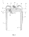
- Figure 1 is a cross section of an earth removal member, such as a casing bit 1, according to one embodiment of the present invention.
- the earth removal member may be a drill bit, reamer shoe, a pilot bit, a core bit, or a hammer bit.
- the casing bit 1 may include a body 5, a head 10, one or more blades 15a,b, one or more cutters 20, one or more stabilizers 25, and one or more nozzles 100.
- the body 5, the head 10, and the blades 15a,b may be integrally formed, such as by casting.
- the body 5 may be tubular and have a threaded inner surface 5t for connection with a bottom of a casing or liner string (not shown) or a casing adapter having a pin or box for connection with the casing or liner bottom. Since the blades 15a,b may be formed integrally with the head 10, the casing bit 1 may be classified as a fixed-cutter bit.
- the head 210 and blades 215a,b may be formed integrally, such as by casting, and the head 210 may include a threaded outer surface 210c for connection with a separately formed tubular body (not shown) having a threaded inner surface. Additionally or alternatively, the casing adapter may be welded to the body.
- the head 10 may include a front or face 10f and a side 10g.
- the face 10f may be milled/drilled through and the side 10g may remain after drill/mill-through.
- the face 10f may be milled/drilled through after cementing the casing and the casing bit to the wellbore.
- the blades 15a may each extend from the side 10g radially or helically to a center of the face 10f.
- the blades 15b may extend radially or helically from the side 10g to a substantial distance toward the face center, such as greater than or equal to one-third or one-half the radius of the head 10.
- a gage portion of the blades 15a,b may extend radially outward past an outer surface of the head 10.
- a height of the blades may decrease as the blades 15a,b extend from the side 10g toward the face center.
- Fluid courses may be formed between facial portions of the blades 15a,b and the face 10f and junk slots may be formed between gage portions of the blades and the side 10g.
- the fluid courses may conduct drilling fluid (not shown) discharged from the nozzles 100 from the face 10f to the junk slots, thereby carrying cuttings from the blades 15a,b.
- the cutters 20 may be bonded into respective recesses 15r formed along each blade 15a,b.
- the cutters 20 may be made from a super-hard material, such as polycrystalline diamond compact (PDC), natural diamond, or cubic boron nitride.
- the PDC may be conventional, cellular, or thermally stable (TSP).
- TSP thermally stable
- the cutters 20 may be bonded into the recesses 15r, such as by brazing, welding, soldering, or using an adhesive.
- the cutters 20 may be disposed
- the cutters 20 may be fastened to the blades 15a,b.
- the blades 15a,b may be omitted and the cutters 20 may be disposed in the head 10, such as in the face 10f and/or side 10g.
- the stabilizers 25 may extend longitudinally and/or helically along the body 5.
- the stabilizers 25 may be aligned with the blades 15a,b and also have fluid channels formed therebetween.
- An outer surface of the stabilizers 25 may extend outward past the gage portion of each blade 15a,b.
- Inserts such as buttons (not shown), may be disposed along an outer surface of each of the stabilizers 25.
- the inserts may be made from a wear-resistant material, such as a ceramic or cermet (i.e., tungsten carbide).
- the inserts may be brazed, welded, or pressed into recesses formed in the outer surface of the stabilizers 25 so that the buttons are flush with or extend outward past the stabilizer outer surface.
- the stabilizers 25 may also serve to rotationally couple the body 10 and the side 10g to the wellbore during drill/mill-through as the casing/liner and the casing bit 1 may be cemented to the wellbore before drill/mill-through.
- the body 5, the head 10, and the blades 15 may be made from a metal or alloy, such as steel, or a composite, such as a cermet.
- the steel may be a low alloy or plain carbon steel.
- the steel may have a high yield strength, such as greater than or equal to thirty-six ksi; preferably fifty ksi; more preferably sixty-five ksi; or most preferably eighty ksi.
- the high strength may provide sufficient erosion-resistance so that an outer surface of the body, head, and blades need not be hard-faced.
- the steel may or may not be a High Strength Low Alloy Steel (HSLA) as designated by ASTM standards.
- HSLA High Strength Low Alloy Steel
- a thickness 10t of the face 10f may be sufficient, such as greater than or equal to one inch or one and a half inches, to receive the nozzles 100.
- the thickness, strength/hardness, and/or ferrous nature of the head material may disqualify the casing bit 1 from being drillable by either a standard drill bit, such as a roller cone, diamond matrix, or PDC bit, or a similar casing bit such that a mill bit or hybrid mill-drill bit may be required to mill the casing bit 1 as opposed to simply drilling through the casing bit 1.
- the blades 15a,b may be bonded or otherwise attached to the head 10, such as by welding, brazing, soldering, or using an adhesive.
- the blades may be made from a drillable material, such as a nonferrous metal or alloy (i.e., copper, brass, bronze, aluminum, zinc, tin, or alloys thereof), a polymer, or composite.
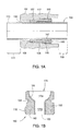
- FIG. 1A is an enlarged cross-section of the nozzle 100.
- the nozzle 100 may include a retainer 105 and a flow tube 110.
- the flow tube 110 may be made from an erosion resistant material, such as a ceramic or cermet (i.e., tungsten carbide).
- the flow tube 110 may be thin to facilitate drilling/milling of the flow tube 110.
- the flow tube 110 may have a substantially uniform inner diameter bore along its length to form a substantially straight bore through the flow tube 110.
- the substantially straight bore of the flow tube 110 may maintain a minimal thickness along the length of the flow tube 110, thus enhancing drillability/millability of the flow tube 110.
- the internal profile of the flow tube 110 formed by the substantially straight bore therethrough potentially decreases erosion of one or more portions of the nozzle 100 because the drilling fluid does not have to change direction due to obstructions within the bore when flowing through the nozzle 100.
- the retainer 105 may be a tubular and made from a drillable material, such as a nonferrous metal or alloy (i.e., copper, brass, bronze, aluminum, zinc, tin, or alloys thereof), a polymer, or composite.
- the flow tube 110 may be mounted within the retainer 105.
- An inner surface of the retainer 105 may form a recess for receiving an adhesive 147, thereby bonding the flow tube 110 to the retainer.
- a surface of the face 10f defining the port 10p may form a profile 117 for receiving the retainer 105.
- An outer surface of the retainer 105 may have a seal groove 108 receiving a seal 107 for preventing fluid leakage across the interface formed between an outer surface of the retainer 105 and the profile 117.
- the seal groove 108 may be formed in an inner surface of the face 10f.
- the retainer 105 may be fastened to the face 10f, such as by a threaded connection 115.
- the retainer 105 may be fastened to the face 10f by a retainer clip or snap ring.
- the retainer 105 may include an installation and removal feature, such as slots 140.
- fastening the retainer 105 to the face 10f instead of permanently bonding the retainer allows the nozzles 100 to be replaced at the drilling rig with a different size.
- an optimum inside diameter of the nozzle 100 or flow tube 110 may not be determined until after the casing bit 1 has been delivered to the drilling rig.
- the retainer 105 may be bonded to the face, such as by welding, brazing, or using an adhesive or solder.
- the casing bit 1 may be shipped to the rig and the optimum size flow tubes may be adhered to the retainers at the rig.
- the flow tube 110 may be bonded to the retainer 105, such as by welding, brazing, or soldering.
- the flow tube may be fastened to the retainer.
- the flow tube may be galled to the retainer and/or the retainer galled to the face by using an anti-lubricant, such as discussed and illustrated in U.S. Prov. App. No. 61/153,572 (Atty. Dock. No. WEAT/0928L), filed February 18, 2009, which is herein incorporated by reference in its entirety.
- the flow tube 110 may have a length greater than or equal to the retainer 105. If the length of the flow tube 110 is extended, the flow tube 110 may be positioned as desired within the retainer 105 to adjust an exit standoff 109 and entry standoff 111, thereby adjusting entry and exit points of the drilling fluid to minimize fluid erosion and/or to allow the exit point of the drilling fluid from the nozzle 100 to be positioned closer to the formation.
- the entry point may be adjusted to create a zone 130 in the drilling fluid flow where high velocities and turbulence do not exist, thereby protecting the relatively soft retainer 105 from erosion. Alternatively, the entry and exit points may be reversed.
- Figure 1B is a cross-section of an alternative nozzle 150.
- the nozzle 150 may include an annular body 155.
- the body 155 may have a bore 175 formed therethrough with an inlet having a concave enlarged portion 175a which communicates with a cylindrical smaller diameter portion 175b leading to an outlet 180.
- the geometry of the through-bore 175 is such that drilling fluid is discharges at high velocity from the outlet 180.
- An inner surface of the body 155 may be coated with an erosion-resistant material 160.
- the erosion-resistant material may be a metal or alloy, such as chrome, or a ceramic or cermet, such as tungsten carbide.
- the body 155 may be made from a drillable material (discussed above). If the coating 160 is chrome and the body is copper, the chrome may be deposited on the copper by electroplating.
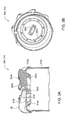
- Figure 2A is a cross-section of a head 210 of a casing bit 200, according to another embodiment of the present invention.
- Figure 2B is a rear end view of the head 210.
- the casing bit 200 may include a body (not shown), the head 210, one or more blades 215a,b, one or more cutters 20, one or more stabilizers (not shown), and one or more nozzles 100.
- the head 210 may include a threaded outer surface 210c for connection to the body.
- the head, blades, and body may be integrally formed, such as by casting.
- the casing bit 200 may be similar to the casing bit 1 except that a nominal thickness 210t of the face has been substantially reduced relative to the thickness 10t so that the casing bit may be drilled through by a standard drill bit (discussed above) or another casing bit without substantial damage thereto.
- the thickness 210t may be less than or equal to one, three-quarters, one-half, or three-eighths of an inch.
- a thickness of the face proximate to each of the ports 210p may be increased by a boss 250.
- Each boss 250 may be tubular and integrally formed with the head 210, such as by casting.
- Each boss 250 may extend from a rear surface of the face 210f.
- Each boss 250 may locally increase the face thickness to greater than or equal to one inch or one and one-half inches. In this manner, the substantial reduction in nominal thickness of the high strength steel correspondingly substantially increases the drillability of the casing bit and the bosses compensate the facial thickness only where needed to receive the nozzles without substantial penalty to the drillability of the casing bit 200.
- Figure 3A is a cross-section of a head 310 of a casing bit 300, according to another embodiment of the present invention.
- Figure 3B is a rear end view of the head 310.
- the casing bit 300 may include a body (not shown), a head 310, one or more blades 315a,b, one or more cutters 20, one or more stabilizers (not shown), and one or more nozzles (not shown).
- the head 310 may include a threaded outer surface 310c for connection to the body.
- the head, blades, and body may be integrally formed, such as by casting.
- the casing bit 300 may be similar to the casing bit 1 except that a nominal thickness 310t of the face 310f has been substantially reduced relative to the thickness 10t so that the casing bit may be drilled through by a standard drill bit (discussed above) or another casing bit without substantial damage thereto.
- the thickness 310t may be less than or equal to one, three-quarters, one-half, or three-eighths of an inch.
- a thickness of the face 310f proximate to the ports 310p may be increased by a boss 350i,o.
- Each boss 350i,o may be integrally formed with the head 310, such as by casting.
- Each boss 350i,o may locally increase the face thickness to greater than or equal to one inch or one and one-half inches.
- an outer set of ports 310p may be radially aligned and the facial thickness increased by an outer boss ring 350o.
- a boss block 350i may increase the facial thickness for an inner set of ports.
- the inner set of ports may include more than two ports and an inner boss ring may be used instead of the boss block to increase the facial thickness.
- the bosses 350i,o may offer a continuous drill-through profile as compared to the individually arranged bosses 250.
- bosses 350i,o substantially increase a volume of the high strength material in the head 310, the bosses may still improve drillability relative to the bosses 250 as the individual bosses 250 may break free during drill-through, thereby hindering drill-through or even damaging the drill-through bit.
- Figure 4A is a cross section of a casing bit 400, according to another embodiment of the present invention.
- Figure 4B is an exploded assembly of the casing bit.
- Figure 4C is an end view of the head of the casing bit.
- the casing bit 400 may include a body 405, a head 410, one or more blades 415a,b, one or more cutters 20, one or more stabilizers 425, a nozzle adapter 450, and one or more nozzles 100.
- the casing bit 400 may be similar to the casing bit 1 except that a nominal thickness 410t of the face 410f has been substantially reduced relative to the thickness 10t so that the casing bit may be drilled through by a standard drill bit (discussed above) or another casing bit without substantial damage thereto.
- the thickness 410t may be less than or equal to one, three-quarters, one-half, or three-eighths of an inch.
- the nozzle adapter 450 may be fastened to the head 410, such as by a threaded connection 450c, thereby longitudinally and rotationally coupling the nozzle adapter to the head.
- the nozzle adapter 450 may be coupled to the head by an interference fit, such as a press or shrink fit.
- the nozzle adapter 450 may have one or more splines or keys formed on an outer surface thereof in engagement with corresponding splines or keyways formed on an inner surface of the head, thereby rotationally coupling the head and the nozzle adapter, and may be longitudinally coupled to the head by one or more fasteners.
- the nozzle adapter 450 may be made from a drillable material, such as a nonferrous metal or alloy (i.e., copper, brass, bronze, aluminum, zinc, tin, or alloys thereof), a polymer, or a composite.
- the nozzle adapter 450 may have a disk and a rim.
- the disk may have a thickness 450t.
- the thickness 450t may be sufficient to accommodate the nozzles 100, such as greater than or equal to one inch or one and one-half inches, or a combination of the facial thickness 410t and the nozzle adapter thickness 450t may be sufficient to accommodate the nozzles 100.
- the nozzle 100 may be disposed in the adapter port 450p and may extend into or through the face port 410p. Alternatively, the nozzle 100 may not extend into or through the face port 410p.
- the nozzle adapter 450 may be further anchored to the head to facilitate drill-through.
- Each of the adapter thread and the head thread may have one or more recesses formed therein (only adapter recesses 450r shown).
- the nozzle adapter 450 may be screwed into the head until the connection 450c is tight and then the recesses 450r may be aligned.
- a key 456 may be inserted into each pair of aligned recesses, thereby ensuring that the nozzle adapter remains rotationally coupled to the head 410 during drill through.
- the keys 456 may be longitudinally kept with a fastener, such as a snap ring 454.
- Ports 410p, 450p may be formed through the face 410f and nozzle adapter 450 after the adapter is connected to the head 410.
- the adapter surface defining each port 450p may be threaded for fastening the nozzle retainer 105 thereto. The thread may or may not extend into the face 410f.
- a seal such as an o-ring 452, may be disposed between the adapter and the head.
- the nozzle adapter may be bonded to the head, such as by an adhesive, solder, weld, or braze or fastened with a different fastener, such as pins or set screws.
- the nozzle adapter may be galled to the head by using an anti-lubricant, such as discussed and illustrated in the '572 Provisional.
- the nozzle may be bonded to the nozzle adapter, such as by an adhesive, solder, weld, or braze.
- the nozzle may be galled to the nozzle adapter by using an anti-lubricant.
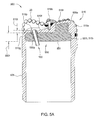
- Figure 5A is a cross section of a casing bit 500, according to another embodiment of the present invention.
- Figure 5B is an isometric view of a nozzle adapter 550 of the casing bit 500.
- the casing bit 500 may include a body 505, a head 510, one or more blades 515a,b, one or more cutters 20, one or more stabilizers (not shown), a nozzle adapter 550, and one or more nozzles 100 (one shown).
- the casing bit 500 may be similar to the casing bit 1 except that a nominal thickness 510t of the face 510f has been substantially reduced relative to the thickness 10t so that the casing bit may be drilled through by a standard drill bit (discussed above) or another casing bit without substantial damage thereto.
- the thickness 510t may be less than or equal to one, three-quarters, one-half, or three-eighths of an inch.
- the nozzle adapter 550 may have a disk 551 and one or more anchors 555a,b.
- the disk 551 may have a thickness 550t.
- the thickness 550t may be sufficient to accommodate the nozzles 100, such as greater than or equal to one inch or one and one-half inches, or a combination of the facial thickness 510t and the disk thickness 550t may be sufficient to accommodate the nozzles 100.
- the adapter 550 may be cast into the head 510 by using the head as a mold.
- the nozzle adapter 550 may be longitudinally and rotationally coupled to the head 510 by a locking profile 510r formed in the head.
- a mating profile 551t may be formed.
- the profiles may include one or more rows of tabs 551t and grooves 510r, each row including one or more tabs and grooves, each tab/groove extending partially around the head/adapter.
- the nozzle adapter 550 may have the tabs 551t and the head 510 may have the grooves 510r or vice versa.
- the nozzle adapter 550 may be made from a drillable material, such as a nonferrous metal or alloy (i.e., copper, brass, bronze, aluminum, zinc, tin, or alloys thereof), a polymer, or a composite. If the material is metallic, the head 510 may be inverted and the molten metallic material may be poured into the head. After cooling, any voids formed due to a different thermal expansion coefficient (TEC) between the head material and the adapter material may be filled by injecting a solidifying filler, such as a polymer, into an interface between the head and the nozzle adapter to prevent erosion due to leakage of drilling fluid.
- TEC thermal expansion coefficient
- the ports 510p,550p may be drilled and tapped and the nozzles 100 installed. If the adapter material is a polymer, liquid polymer may be injected into the head 510 and allowed to solidify. The ports 510p,550p may then be drilled and tapped and the nozzles 100 installed.
- a recess 515r may be formed through the face 510f and into each blade 515a,b, thereby removing a substantial volume of the high strength material from the blades 515a,b.
- Casting/molding the nozzle adapter into the head may form the disk 551 and the one or more anchors 555a,b.
- Each recess 515r may be sized so as to not substantially weaken the respective blade 515a,b.
- the anchors 555a,b may rotationally couple the nozzle adapter to the head during drill-through.
- the anchors 555a,b may further serve to facilitate drillability by smoothing a drill-through path for the drill-through bit and by breaking chips of the casing bit 500 during drill through.
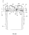
- Figure 6A is a cross section of a casing bit 600, according to another embodiment of the present invention.
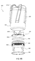
- Figure 6B is an exploded assembly of the casing bit 600.
- the casing bit 600 may include a body 605, a head 610, one or more blades 615a,b, one or more cutters 20, one or more stabilizers 625, a nozzle adapter 650, a plug 660, and one or more nozzles 100.
- the casing bit 600 may be similar to the casing bit 1 except that a nominal thickness 610t of the face 610f has been substantially reduced relative to the thickness 10t so that the casing bit may be drilled through by a standard drill bit (discussed above) or another casing bit without substantial damage thereto.
- the thickness 610t may be less than or equal to one, three-quarters, one-half, or three-eighths of an inch.
- the nozzle adapter 650 may have a disk 651 and one or more anchors 655a,b.
- the disk 651 may have a thickness 650t.
- the plug 660 may have a disk and a rim.
- the plug disk may have a thickness 660t.
- the thicknesses 650t, 660t may be sufficient to accommodate the nozzles 100, such as greater than or equal to one inch or one and one-half inches, or a combination of the facial thickness 610t and the adapter/plug thicknesses 650t,660t may be sufficient to accommodate the nozzles 100.
- the adapter 650 may be cast/molded into the head 610 by using the head as a mold.
- the nozzle adapter 650 may be longitudinally and rotationally coupled to the head by the locking profile 651t,610r.
- the plug 660 may be fastened to the head 610, such as by a threaded connection 660c thereby longitudinally and rotationally coupling the plug to the head.
- the plug 660 may be installed after the nozzle adapter 650 has cooled/solidified from casting/molding.
- the plug 660 may be further anchored to the head 610 to facilitate drill-through.
- Each of the plug thread and the head thread may have one or more recesses formed therein (only plug recesses 660r shown).
- the plug may be screwed into the head until the connection 660c is tight and then the recesses 660r may be aligned.
- a key 666 may be inserted into each pair of aligned recesses, thereby ensuring that the plug remains rotationally coupled to the head 610 during drill through.
- the keys 666 may be longitudinally kept with a fastener, such as a snap ring 664.
- the plug 660 may be bonded to the head 610, such as by an adhesive, solder, weld, braze, or galling.
- Each port 610p,650p,660p may be formed through the face/adapter/plug after the plug is connected to the head,.
- a seal such as an O-ring 652 may be disposed between the plug and the head.
- a thickness of the nozzle adapter 650 may be selected so that the nozzle seal 107 engages the plug 660.
- the nozzle adapter 650 and plug 660 may each be made from a drillable material, such as a nonferrous metal or alloy (i.e., copper, brass, bronze, aluminum, zinc, tin, or alloys thereof), a polymer, or a composite.
- the nozzle adapter and plug may be made from the same or different drillable material.
- voids may be formed upon cooling. Addition of the plug 660 provides a separate seal 652 negating risk of erosion of the nozzle adapter due to leakage of the drilling fluid.
- Figure 7A is a cross section of a casing bit 700, according to another embodiment of the present invention.
- Figure 7B is an exploded assembly of the casing bit 700.
- the casing bit 700 may include a body 705, a head 710, one or more blades 715a,b, one or more cutters 20, one or more stabilizers 725, the nozzle adapter 450, and one or more nozzles 100.
- the casing bit 700 may be similar to the casing bit 1 except that a nominal thickness 710t of the face 710f has been substantially reduced relative to the thickness 10t so that the casing bit may be drilled through by a standard drill bit (discussed above) or another casing bit without substantial damage thereto.
- the thickness 710t may be less than or equal to one, three-quarters, one-half, or three-eighths of an inch.
- the casing bit 700 may also be similar to the casing bit 400, except that a recess 715r may be formed in one or more of the blades 715a,b, thereby removing a substantial volume of the high strength material from the blades 715a,b.
- Each recess 715r may extend through the face 710f and into each blade 715a,b so that an insert 770a,b may be placed in a respective recess before installation of the nozzle adapter 450.
- the inserts 770a,b may then be retained in the blade recesses 715r by the nozzle adapter.
- Each recess 715r may be sized so as to not substantially weaken the respective blade 715a,b.
- the inserts 770a,b may be made from one of the drillable materials discussed above for the nozzle adapter 450 (the same or different from the selected drillable material for the adapter). Alternatively, the inserts 770a,b may be omitted.
- Figure 8A is a cross section of a casing bit 800, according to another embodiment of the present invention.
- Figure 8B is an isometric view of a nozzle adapter 850 of the casing bit 800.
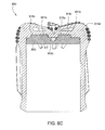
- Figures 8C and 8D are other cross sections of the casing bit 800.
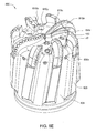
- Figure 8E is an isometric view of the casing bit 800.
- Figure 8F illustrates an outline of a drill-through bit 899 superimposed on the casing bit.
- Figure 8G illustrates the nozzle adapter after being substantially drilled-through.
- the casing bit 800 may include a body 805, a head 810, one or more blades 815a-c, one or more cutters 20, one or more stabilizers 825, a nozzle adapter 850, and one or more nozzles 100.
- the casing bit 800 may be similar to the casing bit 1 except that a nominal thickness 810t of the face 810f has been substantially reduced relative to the thickness 10t so that the casing bit 800 may be drilled through by a standard drill bit (discussed above) or another casing bit without substantial damage thereto.
- the thickness 810t may be less than or equal to one, three-quarters, one-half, or three-eighths of an inch.
- the nozzle adapter 850 may be fastened to the head 810, such as by one or more pins 856p. Each pin 856p may be inserted into an opening 810o formed through the side 810g until a head of the pin seats against a shoulder of the opening.
- a shank of the pin 856p may extend through the opening 810o and into an aligned opening 850o formed in the outer surface of the nozzle adapter 850.
- the pin 856p may be retained by screwing a threaded cap 856c into a threaded portion of the side opening 810o.
- the nozzle adapter 850 may be made from a drillable material, such as a nonferrous metal or alloy (i.e., copper, brass, bronze, aluminum, zinc, tin, or alloys thereof), a polymer, or a composite.
- the pins 856p may also be made from one of the drillable materials (the same as or different from the selected material for the adapter).
- the nozzle adapter 850 may have a disk and one or more anchors 851a,b.
- the nozzle adapter disk may have a thickness 850t.
- the thickness 850t may be sufficient to accommodate the nozzles 100, such as greater than or equal to one inch or one and one-half inches, or a combination of the facial thickness 810t and the adapter thickness 850t may be sufficient to accommodate the nozzles 100.
- a seal such as an o-ring 852, may be disposed between the nozzle adapter 850 and the head 810.
- Ports 810p, 850p may be formed through the face 810f and nozzle adapter 850 after the adapter is connected to the head 810.
- the port 850p may be threaded for fastening the nozzle retainer 105 thereto. The thread may or may not extend into the face 810f.
- the nozzle adapter 850 may be further anchored to the head 810 to facilitate drill-through.
- the anchors may be tabs 851a,b formed on a front surface 850f of the adapter disk.
- the tabs 851a,b may each extend from near a center of the adapter disk radially outward proximately to at least a midpoint of a radius of the disk.
- a recess 816a,b may be formed in/through the face 810f underneath each of the blades 815a for receiving a respective tab 851a,b.
- a depth of the recesses 816a,b may be substantially equal to the facial thickness 810t.
- a length or other dimension of one of the tabs 851a,b may be different than the other of the tabs to ensure a specific rotational alignment of the nozzle adapter 850 with the head 810, thereby allowing the adapter ports 850p to be drilled and tapped before installation of the nozzle adapter 850 in the head 810 for instances where the nozzle distribution is asymmetric.
- the nozzle adapter 850 may further have one or more chip-breakers 852a-c.
- the chip-breakers may include one or more first slots 852a formed in the front surface 850f of the adapter disk and extending from near a center of the disk radially outward nearly to an outer surface of the disk.
- the chip-breakers 852a-c may further include one or more second slots 852b formed in the front surface 850f and extending from near a center of the adapter disk radially outward proximately to a midpoint of a radius of the disk.
- the slots 852a,b may have a depth being a substantial fraction of the thickness 850t, such as greater than or equal to one-half or three-quarters.
- a longitudinal axis of the first slots 852a may be perpendicular to a longitudinal axis of the second slots 852b.
- the chip-breakers 852a-c may further include an opening 852c formed in the front surface 850f and at the center of the adapter disk.
- a depth of the opening 852c may be substantially equal to the depth of the slots 852a,b.
- a diameter of the opening 852c may be a small fraction of a diameter of the adapter disk, such as one-tenth.
- the slots 852a,b may extend from the opening 852c.
- the chip-breakers 852a-c may ensure that debris 890 of the nozzle adapter 850 created due to a profile 899 of the drill-through bit is manageable by fracturing the adapter into a predetermined number of pieces, such as into quadrants.
- the tabs 851a,b may work in conjunction with the chip-breakers 852a-c by rotationally coupling one or more pieces of debris 890 and the head 810 after the chip-breakers 852a-c have separated the adapter 850 into debris 890.
- Tabs 851a,b may not be provided for each quadrant of the debris if nozzles 100 are disposed in the quadrant proximate to the adapter center, thereby serving as anchors for the particular quadrant.
- a recess 815r may be formed in each of the blades 815a, thereby removing a substantial volume of the high strength steel from the blades 815a without substantially weakening the blades.
- the recess 815r may be formed in an exterior surface of each blade 815a, such as a side opposite to a side having the cutters 20.
- the recesses 815r may be in fluid communication with an outlet or exit point of one or more of the nozzles 100, thereby creating turbulence in the drilling fluid discharged from the nozzles 100 during drilling with the casing bit 800 and facilitating cooling and cleaning of the blades 815a.
- the turbulence may also alleviate balling of the casing bit in sticky formations.
- the turbulence may also allow for a reduction in blade height.
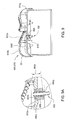
- Figure 9 is a cross section of a casing bit 900, according to another embodiment of the present invention.
- Figure 9A is an enlargement of a portion of Figure 9 .
- the casing bit 900 may include a body (not shown), a head 910, one or more blades 915a,b, one or more cutters 20, one or more stabilizers (not shown), one or more nozzle adapters 950, and one or more nozzles 100.
- the casing bit 900 may be similar to the casing bit 1 except that a nominal thickness 910t of the face 910f has been substantially reduced relative to the thickness 10t so that the casing bit may be drilled through by a standard drill bit (discussed above) or another casing bit without substantial damage thereto.
- the thickness 910t may be less than or equal to one, three-quarters, one-half, or three-eighths of an inch.
- Each nozzle adapter 950 may be made from a drillable material, such as a nonferrous metal or alloy (i.e., copper, brass, bronze, aluminum, zinc, tin, or alloys thereof), a polymer, or a composite.
- Each nozzle adapter 950 may be annular and have a thickness 950t.
- the thickness 950t may be sufficient to accommodate a respective nozzle 100, such as greater than or equal to one inch or one and one-half inches.
- Each nozzle adapter 950 may be fastened to the face 910f, such as by a threaded connection 910p, 950a, thereby longitudinally and rotationally coupling the nozzle adapter to the head.
- An outer surface of each nozzle adapter 950 may be tapered from a larger outer diameter to a smaller outer diameter and form a shoulder 950s between the two diameters. The smaller diameter of the nozzle adapter may be threaded 950a.
- the shoulder 950s may abut an inner surface of the face 910f or a profile may be formed in an inner surface of the face for receiving the adapter.
- Ports 910p, 950p may be formed through the face 910f and nozzle adapter 950 before the adapter is connected to the head 910.
- the port 950p may also be threaded for fastening the nozzle retainer 105 thereto.
- Each adapter 950 may be fastened to the face from inside the head 910.
- the threaded connection between the nozzle retainer 105 and the nozzle adapter 950 may be opposite-handed from the threaded connection between the nozzle adapter and the face. The nozzle may then be fastened to the nozzle adapter from an exterior of the head.
- each flow tube 110 may be adhered to the respective nozzle adapter 950.
- each nozzle adapter 950 may be coupled to the head by an interference fit, such as a press or shrink fit.
- each nozzle adapter may be bonded to the head, such as by an adhesive, solder, weld, or braze.
- the nozzle adapter may be galled to the head by using an anti-lubricant, such as discussed and illustrated in the '572 Provisional.
- FIG. 10 is a cross section of a casing bit 1000, according to another embodiment of the present invention.
- the casing bit 1000 may include a body 1005, a head 1010, one or more blades 1015a , one or more cutters 20, one or more stabilizers (not shown), a nozzle adapter 1050, and one or more nozzles 100.
- the casing bit 1000 may be similar to the casing bit 1 except that a nominal thickness 1010t of the face 1010f has been substantially reduced relative to the thickness 10t so that the casing bit may be drilled through by a standard drill bit (discussed above) or another casing bit without substantial damage thereto.
- the thickness 1010t may be less than or equal to one, three-quarters, one-half, or three-eighths of an inch.
- the nozzle adapter 1050 may be fastened to the head 1010, such as by a threaded connection 1050c, thereby longitudinally and rotationally coupling the nozzle adapter to the head.
- the nozzle adapter 1050 may be made from a drillable material, such as a nonferrous metal or alloy (i.e., copper, brass, bronze, aluminum, zinc, tin, or alloys thereof), a polymer, or a composite.
- the nozzle adapter 1050 may have a disk and a rim.
- the disk may have a thickness 1050t.
- the thickness 1050t may be sufficient to accommodate the nozzles 100, such as greater than or equal to one inch or one and one-half inches, or a combination of the facial thickness 1010t and the nozzle adapter thickness may be sufficient to accommodate the nozzles 100.
- the nozzle adapter 1050 may be further anchored to the head to facilitate drill-through.
- Each of the adapter thread and the head thread may have one or more recesses formed therein (not shown). The nozzle adapter 1050 may be screwed into the head until the connection 1050c is tight and then the recesses may be aligned.
- a key (not shown) may be inserted into each pair of aligned recesses, thereby ensuring that the nozzle adapter remains rotationally coupled to the head 1010 during drill through.
- the keys may be longitudinally kept with a fastener, such as a snap ring (not shown).
- Ports 1010p, 1050p may be formed through the face 1010f and nozzle adapter 1050 after the adapter is connected to the head 1010.
- the adapter surface defining each port 1050p may be threaded for fastening the nozzle retainer 105 thereto. The thread may or may not extend into the face 1010f.
- a seal such as an o-ring 1052, may be disposed between the adapter and the head.
- the adapter 1050 may have a shoulder 1050s for abutment with a corresponding shoulder formed in the head, thereby forming a longitudinal gap 1060 between an end of the adapter and an inner surface of the face 1010f.
- the nozzle adapter 1050 may be coupled to the head by an interference fit, such as a press or shrink fit.
- the nozzle adapter 1050 may have one or more splines or keys formed on an outer surface thereof in engagement with corresponding splines or keyways formed on an inner surface of the head, thereby rotationally coupling the head and the nozzle adapter, and may be longitudinally coupled to the head by one or more fasteners.
- the nozzle adapter may be bonded to the head, such as by an adhesive, solder, weld, or braze or fastened with a different fastener, such as pins or set screws.
- the nozzle adapter may be galled to the head by using an anti-lubricant, such as discussed and illustrated in the '572 Provisional.
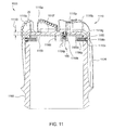
- FIG 11 is a cross section of a casing bit 1100, according to another embodiment of the present invention.
- the casing bit 1100 may include a body 1105, a head 1110, one or more blades 1115a-c, one or more cutters 20, one or more stabilizers 1125, a nozzle adapter 1150, and one or more nozzles 100.
- the casing bit 1100 may be similar to the casing bit 1 except that a nominal thickness 1110t of the face 1110f has been substantially reduced relative to the thickness 10t so that the casing bit 1100 may be drilled through by a standard drill bit (discussed above) or another casing bit without substantial damage thereto.
- the thickness 1110t may be less than or equal to one, three-quarters, one-half, or three-eighths of an inch.
- the nozzle adapter 1150 may be fastened to the head 1110, such as by one or more pins 1156p. Each pin 1156p may be inserted into an opening 1110o formed through the side 1110g until a head of the pin seats against a shoulder of the opening.
- a shank of the pin 1156p may extend through the opening 1110o and into an aligned opening 1150o formed in the outer surface of the nozzle adapter 1150.
- the pin 1156p may be retained by screwing a threaded cap 1156c into a threaded portion of the side opening 1110o.
- the nozzle adapter 1150 may be made from a drillable material, such as a nonferrous metal or alloy (i.e., copper, brass, bronze, aluminum, zinc, tin, or alloys thereof), a polymer, or a composite.
- the pins 1156p may also be made from one of the drillable materials (the same as or different from the selected material for the adapter).
- the nozzle adapter 1150 may have a rim, a disk, and a boss 1150b for each nozzle 100. Each boss 1150b may extend from a rear of the nozzle adapter and have a thickness 1150t. The thickness 1150t may be sufficient to accommodate each nozzle 100, such as greater than or equal to one inch or one and one-half inches, or a combination of the facial thickness 1110t and the boss thickness 1150t may be sufficient to accommodate the nozzles 100.
- a seal, such as an o-ring 1152 may be disposed between the nozzle adapter 1150 and the head 1110. Ports 1110p, 1150p may be formed through the face 1110f and nozzle adapter 1150 before the adapter is connected to the head 1110.
- the port 1150p may be threaded for fastening the nozzle retainer 105 thereto. The thread may or may not extend into the face 1110f.
- the nozzle adapter 1150 may be coupled to the head by an interference fit, such as a press or shrink fit.
- the nozzle adapter 1150 may have one or more splines or keys formed on an outer surface thereof in engagement with corresponding splines or keyways formed on an inner surface of the head, thereby rotationally coupling the head and the nozzle adapter, and may be longitudinally coupled to the head by one or more fasteners.
- the nozzle adapter may be bonded to the head, such as by an adhesive, solder, weld, or braze or fastened with a different fastener, such as set screws.
- the nozzle adapter may be galled to the head by using an anti-lubricant, such as discussed and illustrated in the '572 Provisional.
- Figure 12 is a cross section of a casing bit 1200, according to another embodiment of the present invention.
- the casing bit 1200 may include a body 1205, a head 1210, one or more blades 1215a-c, one or more cutters 20, one or more stabilizers 1225, a nozzle adapter 1250, and one or more nozzles 100.
- the casing bit 1200 may be similar to the casing bit 1 except that a nominal thickness 1210t of the face 1210f has been substantially reduced relative to the thickness 10t so that the casing bit 1200 may be drilled through by a standard drill bit (discussed above) or another casing bit without substantial damage thereto.
- the thickness 1210t may be less than or equal to one, three-quarters, one-half, or three-eighths of an inch.
- the nozzle adapter 1250 may be fastened to the head 1210, such as by one or more pins 1256p. Each pin 1256p may be inserted into an opening 1210o formed through the side 1210g until a head of the pin seats against a shoulder of the opening.
- a shank of the pin 1256p may extend through the opening 1210o and into an aligned opening 1250o formed in the outer surface of the nozzle adapter 1250.
- the pin 1256p may be retained by screwing a threaded cap 1256c into a threaded portion of the side opening 1210o.
- the nozzle adapter 1250 may be made from a drillable material, such as a nonferrous metal or alloy (i.e., copper, brass, bronze, aluminum, zinc, tin, or alloys thereof), a polymer, or a composite.
- the pins 1256p may also be made from one of the drillable materials (the same as or different from the selected material for the adapter).
- the nozzle adapter 1250 may have a disk and a boss 1250b for each nozzle 100.
- Each boss 1250b may extend from a front of the nozzle adapter and into a respective face port 1210p so that an end of the boss is flush or slightly sub-flush with a front of the face 1210f.
- Each boss 1250b may have a thickness 1250t. The thickness 1250t may be sufficient to accommodate each nozzle 100, such as greater than or equal to one inch or one and one-half inches.
- a seal, such as an o-ring 1252 may be disposed between the nozzle adapter 1250 and the head 1210. Ports 1210p, 1250p may be formed through the face 1210f and nozzle adapter 1250 before the adapter is connected to the head 1210.
- the port 1250p may be threaded for fastening the nozzle retainer 105 thereto.
- a longitudinal gap 1260 may be formed between an end of the adapter disk and an inner surface of the face 1210f. Alternatively, the gap 1260 may be omitted.
- the nozzle adapter 1250 may be coupled to the head by an interference fit, such as a press or shrink fit.
- the nozzle adapter 1250 may have one or more splines or keys formed on an outer surface thereof in engagement with corresponding splines or keyways formed on an inner surface of the head, thereby rotationally coupling the head and the nozzle adapter, and may be longitudinally coupled to the head by one or more fasteners.
- the nozzle adapter may be bonded to the head, such as by an adhesive, solder, weld, or braze or fastened with a different fastener, such as set screws.
- the nozzle adapter may be galled to the head by using an anti-lubricant, such as discussed and illustrated in the '572 Provisional.
- Figure 13 is a cross section of a casing bit 1300, according to another embodiment of the present invention.
- the casing bit 1300 may include a body 1305, a head 1310, one or more blades 1315a-c, one or more cutters 20, one or more stabilizers 1325, a nozzle adapter 1350, and one or more nozzles 100.
- the casing bit 1300 may be similar to the casing bit 1 except that a nominal thickness 1310t of the face 1310f has been substantially reduced relative to the thickness 10t so that the casing bit 1300 may be drilled through by a standard drill bit (discussed above) or another casing bit without substantial damage thereto.
- the thickness 1310t may be less than or equal to one, three-quarters, one-half, or three-eighths of an inch.
- the nozzle adapter 1350 may be fastened to the head 1310, such as by one or more pins 1356p. Each pin 1356p may be inserted into an opening 1310o formed through the side 1310g until a head of the pin seats against a shoulder of the opening.
- a shank of the pin 1356p may extend through the opening 1310o and into an aligned opening 1350o formed in the outer surface of the nozzle adapter 1350.
- the pin 1356p may be retained by screwing a threaded cap 1356c into a threaded portion of the side opening 1310o.
- the nozzle adapter 1350 may be made from a drillable material, such as a nonferrous metal or alloy (i.e., copper, brass, bronze, aluminum, zinc, tin, or alloys thereof), a polymer, or a composite.
- the pins 1356p may also be made from one of the drillable materials (the same as or different from the selected material for the adapter).
- the nozzle adapter 1350 may have a rim, a disk, and a boss 1350b for each nozzle 100. Each boss 1350b may extend from a rear of the nozzle adapter and have a thickness 1350t. The thickness 1350t may be sufficient to accommodate each nozzle 100, such as greater than or equal to one inch or one and one-half inches, or a combination of the facial thickness 1310t and the boss thickness 1350t may be sufficient to accommodate the nozzles 100.
- a seal, such as an o-ring 1352 may be disposed between the nozzle adapter 1350 and the head 1310. Ports 1310p, 1350p may be formed through the face 1310f and nozzle adapter 1350 before the adapter is connected to the head 1310.
- the port 1350p may be threaded for fastening the nozzle retainer 105 thereto. The thread may or may not extend into the face 1310f.
- a longitudinal gap 1360 may be formed between an end of the adapter 1350 and an inner surface of the face 1310f. Alternatively, the gap 1360 may be omitted.
- the nozzle adapter 1350 may be coupled to the head by an interference fit, such as a press or shrink fit.
- the nozzle adapter 1350 may have one or more splines or keys formed on an outer surface thereof in engagement with corresponding splines or keyways formed on an inner surface of the head, thereby rotationally coupling the head and the nozzle adapter, and may be longitudinally coupled to the head by one or more fasteners.
- the nozzle adapter may be bonded to the head, such as by an adhesive, solder, weld, or braze or fastened with a different fastener, such as set screws.
- the nozzle adapter may be galled to the head by using an anti-lubricant, such as discussed and illustrated in the '572 Provisional.
- Figure 14 is a cross section of a casing bit 1400, according to another embodiment of the present invention.
- the casing bit 1400 may include a body 1405, a head 1410, one or more blades 1415a-c, one or more cutters 20, one or more stabilizers 1425, a nozzle adapter 1450, and one or more nozzles 100.
- the casing bit 1400 may be similar to the casing bit 1 except that a nominal thickness 1410t of the face 1410f has been substantially reduced relative to the thickness 10t so that the casing bit 1400 may be drilled through by a standard drill bit (discussed above) or another casing bit without substantial damage thereto.
- the thickness 1410t may be less than or equal to one, three-quarters, one-half, or three-eighths of an inch.
- the nozzle adapter 1450 may be fastened to the head 1410, such as by one or more pins 1456p. Each pin 1456p may be inserted into an opening 1410o formed through the side 1410g until a head of the pin seats against a shoulder of the opening.
- a shank of the pin 1456p may extend through the opening 1410o and into an aligned opening 1450o formed in the outer surface of the nozzle adapter 1450.
- the pin 1456p may be retained by screwing a threaded cap 1456c into a threaded portion of the side opening 1410o.
- the nozzle adapter 1450 may be made from a drillable material, such as a nonferrous metal or alloy (i.e., copper, brass, bronze, aluminum, zinc, tin, or alloys thereof), a polymer, or a composite.
- the pins 1456p may also be made from one of the drillable materials (the same as or different from the selected material for the adapter).
- the nozzle adapter 1450 may have a disk and a boss 1450b for each nozzle 100.
- Each boss 1450b may extend from a front of the nozzle adapter and into a respective face port 1410p and engage a shoulder 1410s formed in the face port 1410p.
- Each boss 1450b may have a thickness 1450t.
- the thickness 1450t may be sufficient to accommodate each nozzle 100, such as greater than or equal to one inch or one and one-half inches, or a combination of the facial thickness 1410t and the boss thickness 1450t may be sufficient to accommodate the nozzles 100.
- a seal, such as an o-ring 1452, may be disposed between the nozzle adapter 1450 and the head 1410.
- Ports 1410p, 1450p may be formed through the face 1410f and nozzle adapter 1450 before the adapter is connected to the head 1410.
- the port 1450p may be threaded for fastening the nozzle retainer 105 thereto.
- the thread may or may not extend into the face 1410f.
- a longitudinal gap 1460 may be formed between an end of the adapter disk and an inner surface of the face 1410f. Alternatively, the gap 1460 may be omitted.
- the nozzle adapter 1450 may be coupled to the head by an interference fit, such as a press or shrink fit.
- the nozzle adapter 1450 may have one or more splines or keys formed on an outer surface thereof in engagement with corresponding splines or keyways formed on an inner surface of the head, thereby rotationally coupling the head and the nozzle adapter, and may be longitudinally coupled to the head by one or more fasteners.
- the nozzle adapter may be bonded to the head, such as by an adhesive, solder, weld, or braze or fastened with a different fastener, such as set screws.
- the nozzle adapter may be galled to the head by using an anti-lubricant, such as discussed and illustrated in the '572 Provisional.
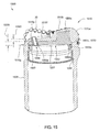
- Figure 15 is a cross section of a casing bit 1500, according to another embodiment of the present invention.
- the casing bit 1500 may include a body 1505, a head 1510, one or more blades 1515a, one or more cutters 20, one or more stabilizers (not shown), a nozzle adapter 1550, a plug 1560, and one or more nozzles 100a.
- the casing bit 1500 may be similar to the casing bit 1 except that a nominal thickness 1510t of the face 1510f has been substantially reduced relative to the thickness 10t so that the casing bit may be drilled through by a standard drill bit (discussed above) or another casing bit without substantial damage thereto.
- the thickness 1510t may be less than or equal to one, three-quarters, one-half, or three-eighths of an inch.
- the nozzle 100a may be disposed in the adapter port 1550p and may extend into or through the face port 1510p.
- the nozzle adapter 1550 may have a disk 1551 and one or more anchors 1555a.
- the disk 1551 may have a thickness 1550t.
- the thickness 1550t may be sufficient to accommodate the nozzles 100a, such as greater than or equal to one inch or one and one-half inches, or a combination of the facial thickness 1510t and the adapter thickness 1550t may be sufficient to accommodate the nozzles 100a. Similar to the nozzle adapters 550,650, the adapter 1550 may be cast/molded into the head 1510 by using the head as a mold. The nozzle adapter 1550 may be longitudinally and rotationally coupled to the head by the locking profile 1551t, 1510r.
- the plug 1560 may be annular and may be fastened to the head 1510, such as by a threaded connection, thereby longitudinally and rotationally coupling the plug to the head.
- the plug 1560 may be installed after the nozzle adapter 1550 has cooled/solidified from casting/molding.
- the plug 1560 may be further anchored to the head 1510 to facilitate drill-through.
- Each of the plug thread and the head thread may have one or more recesses formed therein. The plug may be screwed into the head until the connection is tight and then the recesses may be aligned. A key may be inserted into each pair of aligned recesses, thereby ensuring that the plug remains rotationally coupled to the head during drill through.
- the keys may be longitudinally kept with a fastener, such as a snap ring 1564.
- the plug 1560 may be bonded to the head 1510, such as by an adhesive, solder, weld, braze, or galling.
- one or more seals such as O-rings 1552a,b, may be disposed between the plug and the head and/or between the plug and nozzle adapter.
- the nozzle adapter 1550 and plug 1560 may each be made from a drillable material, such as a nonferrous metal or alloy (i.e., copper, brass, bronze, aluminum, zinc, tin, or alloys thereof), a polymer, or a composite.
- the nozzle adapter and plug may be made from the same or different drillable material.
- voids may be formed upon cooling. Addition of the plug 1560 provides separate seals 1552a,b negating risk of erosion of the nozzle adapter due to leakage of the drilling fluid.
- Each nozzle 100a may be modified from the nozzle 100 so as not to extend into a bore of the plug 1560.
- each nozzle may be the nozzle 100 and may extend into the plug bore.
- the plug may include a disk having a port formed therethrough corresponding to each nozzle and be fastened to the head using pins or screws.
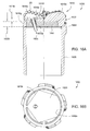
- Figure 16A is a cross section of a casing bit 1600, according to another embodiment of the present invention.
- Figure 16B a rear end view of the head 1610.
- the casing bit 1600 may include a body 1605, a head 1610, one or more blades 1615a, one or more cutters 20, one or more stabilizers (not shown), a nozzle adapter 1650, and one or more nozzles 100b.
- the casing bit 1600 may be similar to the casing bit 1 except that a nominal thickness 1610t of the face 1610f has been substantially reduced relative to the thickness 10t so that the casing bit may be drilled through by a standard drill bit (discussed above) or another casing bit without substantial damage thereto.
- the thickness 1610t may be less than or equal to one, three-quarters, one-half, or three-eighths of an inch.
- the nozzle adapter 1650 may be made from a drillable material, such as a nonferrous metal or alloy (i.e., copper, brass, bronze, aluminum, zinc, tin, or alloys thereof), a polymer, or a composite.
- the nozzle adapter 1650 may be a disk having a thickness 1650t.
- the thickness 1650t may be sufficient to accommodate the nozzles 100b, such as greater than or equal to one inch or one and one-half inches, or a combination of the facial thickness 1610t and the nozzle adapter thickness 1650t may be sufficient to accommodate the nozzles 100b.
- the nozzle 100b may be disposed in the adapter port 1650p and may extend into or through the face port 1610p. Each nozzle 100b may be modified from the nozzle 100 so that a head of the nozzle retainer seats 1610s in a profile formed in the face port 1610p, thereby longitudinally coupling the nozzle adapter 1650 to the head 1610.
- Each nozzle 100b may also serve to rotationally couple the nozzle adapter to the head.
- the nozzle adapter 1650 may be fastened to the head 1610, such as by snap ring 1664, thereby longitudinally coupling the nozzle adapter to the head.
- the nozzle adapter 1650 may be rotationally coupled to the head by a profile formed in an inner surface 1610i of the head and an outer surface 1650o of the nozzle adapter.
- the profile may be polygonal, such as a pentagon.
- the profile may be splines or keys/keyways.
- a seal such as an o-ring 1652, may be disposed between the adapter and the head.
- the nozzle adapter may be bonded to the head, such as by an adhesive, solder, weld, or braze or fastened with a different fastener, such as pins or set screws.
- the nozzle adapter may be galled to the head by using an anti-lubricant, such as discussed and illustrated in the '572 Provisional.
- the nozzle 100b may be used to longitudinally and/or rotationally couple the nozzle adapter to the head for any of the other casing bits 400-1500.
- any of the casing bits 1, 200-1600 may be modified so that the bodies thereof include one or more circulation ports as discussed and illustrated in U.S. Pat. App. Pub. No. 2006/0185855 (Atty. Dock. No. WEAT/0676), which is herein incorporated by reference in its entirety.
- the circulation ports may be formed through a wall of the body and initially sealed by a frangible member, such as a burst tube, lining an inner surface of the body wall.
- the circulation ports may be useful in a drilling with casing/liner operation to facilitate circulation and cementing of the casing/liner after the casing/liner is drilled to the desired depth.
- the burst tube may be made from a drillable material. During drilling with the casing bit, the circulation ports may remain sealed. When circulating before cementing an injection rate of circulation fluid, such as drilling mud, may be increased to rupture the burst tube. The circulation and cementing operation may be performed and the casing bit may then be drilled through.
- circulation fluid such as drilling mud
- any of the casing bits 1, 200-1600 such as the number and placement of the nozzles 100, length of standoffs 109, 111, and flow tube 110 diameter (or body 175 diameter), may be customized for each specific application.
- Factors may include weight on bit, rotary speed of bit, hole depth, hole direction, drilling fluid parameters, circulation rate, gage of the hole, and formation parameters.
- fastening of the nozzles 100, 150 to the bits 1, 200-1400 allows change-out of the nozzles 100, 150 at the rig-site. This allows the rig operator greater flexibility to adjust to actual conditions experienced downhole.
- any of the other casing bits 400-900, 1100, 1500, 1600 may include a longitudinal gap formed between an end of the adapter and an inner surface of the face.
- any of the casing bits 1, 200-1600 may be used to run-in or ream-in casing/liner into a pre-drilled wellbore.
- the blades 15, 215-1615 of any of the casing bits 1, 200-1600 may be omitted and the cutters 20 may be disposed in the respective heads, such as in the face and/or side.
- the blades 15, 215-1615 of any of the casing bits 1, 200-1600 may be bonded or otherwise attached to the respective heads, such as by welding, brazing, soldering, or using an adhesive.
- the blades may be made from a drillable material, such as a nonferrous metal or alloy (i.e., copper, brass, bronze, aluminum, zinc, tin, or alloys thereof), a polymer, or composite.
- any of the nozzle adapters 450-1650 may be bonded to the respective heads 410-1610, such as by an adhesive, solder, weld, or braze or fastened with any fastener, such as thread, pins or set screws.
- any of the nozzle adapters may be galled to the head by using an anti-lubricant, such as discussed and illustrated in the '572 Provisional.
- any of the nozzles 100, 100a, 100b may be bonded to the respective nozzle adapters 450-1650, such as by an adhesive, solder, weld, or braze.
- any of the nozzles may be galled to the respective nozzle adapters by using an anti-lubricant.
- the retainers 105 of any of the nozzles 100, 100a, 100b may be omitted and the flow tubes 110 may instead be bonded, fastened, or galled to the respective bosses/adapters 250-1650.
Landscapes
- Engineering & Computer Science (AREA)
- Life Sciences & Earth Sciences (AREA)
- Geology (AREA)
- Mining & Mineral Resources (AREA)
- Physics & Mathematics (AREA)
- Environmental & Geological Engineering (AREA)
- Fluid Mechanics (AREA)
- General Life Sciences & Earth Sciences (AREA)
- Geochemistry & Mineralogy (AREA)
- Mechanical Engineering (AREA)
- Earth Drilling (AREA)
Priority Applications (1)
| Application Number | Priority Date | Filing Date | Title |
|---|---|---|---|
| EP17177922.6A EP3279424A1 (de) | 2009-09-11 | 2010-09-10 | Erdentfernungselement mit funktionen zur ermöglichung einer durchbohrung |
Applications Claiming Priority (1)
| Application Number | Priority Date | Filing Date | Title |
|---|---|---|---|
| US12/558,277 US8074749B2 (en) | 2009-09-11 | 2009-09-11 | Earth removal member with features for facilitating drill-through |
Related Child Applications (1)
| Application Number | Title | Priority Date | Filing Date |
|---|---|---|---|
| EP17177922.6A Division EP3279424A1 (de) | 2009-09-11 | 2010-09-10 | Erdentfernungselement mit funktionen zur ermöglichung einer durchbohrung |
Publications (3)
| Publication Number | Publication Date |
|---|---|
| EP2302159A2 true EP2302159A2 (de) | 2011-03-30 |
| EP2302159A3 EP2302159A3 (de) | 2012-04-04 |
| EP2302159B1 EP2302159B1 (de) | 2017-06-28 |
Family
ID=43587446
Family Applications (2)
| Application Number | Title | Priority Date | Filing Date |
|---|---|---|---|
| EP10176279.7A Not-in-force EP2302159B1 (de) | 2009-09-11 | 2010-09-10 | Erdabtragungselement mit Funktionen zur Ermöglichung des Durchbohrens |
| EP17177922.6A Withdrawn EP3279424A1 (de) | 2009-09-11 | 2010-09-10 | Erdentfernungselement mit funktionen zur ermöglichung einer durchbohrung |
Family Applications After (1)
| Application Number | Title | Priority Date | Filing Date |
|---|---|---|---|
| EP17177922.6A Withdrawn EP3279424A1 (de) | 2009-09-11 | 2010-09-10 | Erdentfernungselement mit funktionen zur ermöglichung einer durchbohrung |
Country Status (5)
| Country | Link |
|---|---|
| US (3) | US8074749B2 (de) |
| EP (2) | EP2302159B1 (de) |
| AU (4) | AU2010219396B9 (de) |
| CA (1) | CA2714545C (de) |
| DK (1) | DK2302159T3 (de) |
Cited By (1)
| Publication number | Priority date | Publication date | Assignee | Title |
|---|---|---|---|---|
| WO2021224872A1 (en) * | 2020-05-08 | 2021-11-11 | Diamant Drilling Services S.A. | Drill bit |
Families Citing this family (25)
| Publication number | Priority date | Publication date | Assignee | Title |
|---|---|---|---|---|
| WO2009064967A1 (en) * | 2007-11-14 | 2009-05-22 | Baker Hughes Incorporated | Earth-boring tools attachable to a casing string and methods for their manufacture |
| GB0900606D0 (en) | 2009-01-15 | 2009-02-25 | Downhole Products Plc | Tubing shoe |
| US8517123B2 (en) | 2009-05-29 | 2013-08-27 | Varel International, Ind., L.P. | Milling cap for a polycrystalline diamond compact cutter |
| US20110209922A1 (en) * | 2009-06-05 | 2011-09-01 | Varel International | Casing end tool |
| SG10201404788WA (en) | 2009-06-05 | 2014-10-30 | Varel Int Ind Lp | Casing bit and casing reamer designs |
| US8074749B2 (en) | 2009-09-11 | 2011-12-13 | Weatherford/Lamb, Inc. | Earth removal member with features for facilitating drill-through |
| GB201004603D0 (en) * | 2010-03-19 | 2010-05-05 | 2Td Ltd | Drill bit |
| WO2012088323A2 (en) | 2010-12-22 | 2012-06-28 | Weatherford/Lamb, Inc. | Earth removal member with features for facilitating drill-through |
| US8899318B1 (en) | 2014-04-24 | 2014-12-02 | Ronald C. Parsons | Applying an aggregate to expandable tubular |
| US10538983B2 (en) * | 2014-08-06 | 2020-01-21 | Schlumberger Technology Corporation | Milling tools with a secondary attrition system |
| CN105019833B (zh) * | 2015-07-21 | 2017-12-08 | 吉林大学 | 一种仿生自适应pdc钻头 |
| US10428584B2 (en) | 2016-07-13 | 2019-10-01 | Varel International Ind., L.P. | Bit for drilling with casing or liner string and manufacture thereof |
| US10603681B2 (en) * | 2017-03-06 | 2020-03-31 | Engineered Spray Components LLC | Stacked pre-orifices for sprayer nozzles |
| GB201809145D0 (en) | 2018-06-05 | 2018-07-18 | Downhole Products Plc | Guide shoe |
| CN108533183B (zh) * | 2018-06-22 | 2023-08-15 | 西南石油大学 | 一种刀翼上设置有被动旋转喷嘴的pdc钻头 |
| USD940207S1 (en) * | 2018-11-02 | 2022-01-04 | Vulcan Completion Products Uk Limited | Nose for a shoe suitable for use in an oil and gas wellbore |
| CN110607991B (zh) * | 2019-10-14 | 2020-12-18 | 天津立林钻头有限公司 | 一种斧型齿pdc钻头设计方法 |
| CN110671055B (zh) * | 2019-10-14 | 2020-12-18 | 天津立林钻头有限公司 | 一种锥形齿pdc钻头设计方法 |
| CN110725652A (zh) * | 2019-10-18 | 2020-01-24 | 中国石油集团渤海钻探工程有限公司 | 可钻式套管钻井钻头 |
| US11313178B2 (en) | 2020-04-24 | 2022-04-26 | Saudi Arabian Oil Company | Concealed nozzle drill bit |
| WO2022006035A1 (en) | 2020-06-29 | 2022-01-06 | Baker Hughes Oilfield Operations Llc | Tagging assembly including a sacrificial stop component |
| US11913286B2 (en) * | 2021-06-08 | 2024-02-27 | Baker Hughes Oilfield Operations Llc | Earth-boring tools with through-the-blade fluid ports, and related methods |
| WO2022272092A1 (en) * | 2021-06-25 | 2022-12-29 | Schlumberger Technology Corporation | Erosion resistant insert for drill bits |
| CN113775296B (zh) * | 2021-11-11 | 2022-02-18 | 胜利油田海胜实业有限责任公司 | 一种用于泥灰岩勘探的可调口径的pdc钻头 |
| KR102623384B1 (ko) * | 2023-09-08 | 2024-01-09 | 백남진 | 굴착력과 슬라임 배출 기능을 향상시킨 연약지반 굴착용 비트구조체 |
Citations (1)
| Publication number | Priority date | Publication date | Assignee | Title |
|---|---|---|---|---|
| US20060185855A1 (en) | 2002-12-13 | 2006-08-24 | Jordan John C | Retractable joint and cementing shoe for use in completing a wellbore |
Family Cites Families (47)
| Publication number | Priority date | Publication date | Assignee | Title |
|---|---|---|---|---|
| US1388490A (en) * | 1920-09-18 | 1921-08-23 | John R Suman | Rotary earth-boring drill |
| US2408892A (en) * | 1944-07-18 | 1946-10-08 | Reed Roller Bit Co | Slush tube |
| US2721058A (en) * | 1948-09-16 | 1955-10-18 | Reed Roller Bit Co | Drill bit |
| US2738011A (en) | 1953-02-17 | 1956-03-13 | Thomas S Mabry | Means for cementing well liners |
| US3419220A (en) * | 1966-11-30 | 1968-12-31 | Gulf Research Development Co | Nozzles for abrasive-laden slurry |
| US3621910A (en) | 1968-04-22 | 1971-11-23 | A Z Int Tool Co | Method of and apparatus for setting an underwater structure |
| US3645331A (en) * | 1970-08-03 | 1972-02-29 | Exxon Production Research Co | Method for sealing nozzles in a drill bit |
| US3688853A (en) * | 1971-03-01 | 1972-09-05 | William C Maurer | Method and apparatus for replacing nozzles in erosion bits |
| US4273190A (en) | 1979-12-27 | 1981-06-16 | Halliburton Company | Method and apparatus for gravel packing multiple zones |
| US4397355A (en) | 1981-05-29 | 1983-08-09 | Masco Corporation | Whipstock setting method and apparatus |
| US4396077A (en) * | 1981-09-21 | 1983-08-02 | Strata Bit Corporation | Drill bit with carbide coated cutting face |
| US4739845A (en) * | 1987-02-03 | 1988-04-26 | Strata Bit Corporation | Nozzle for rotary bit |
| US4878548A (en) * | 1988-01-21 | 1989-11-07 | Eastman Christensen | Nozzle retention system for a drill bit |
| US5271472A (en) | 1991-08-14 | 1993-12-21 | Atlantic Richfield Company | Drilling with casing and retrievable drill bit |
| US5195591A (en) | 1991-08-30 | 1993-03-23 | Atlantic Richfield Company | Permanent whipstock and placement method |
| US5566762A (en) | 1994-04-06 | 1996-10-22 | Tiw Corporation | Thru tubing tool and method |
| US6263987B1 (en) | 1994-10-14 | 2001-07-24 | Smart Drilling And Completion, Inc. | One pass drilling and completion of extended reach lateral wellbores with drill bit attached to drill string to produce hydrocarbons from offshore platforms |
| GB9504968D0 (en) | 1995-03-11 | 1995-04-26 | Brit Bit Limited | Improved casing shoe |
| US6106200A (en) | 1996-11-12 | 2000-08-22 | Techmo Entwicklungs-Und Vertriebs Gmbh | Process and device for simultaneously drilling and lining a hole |
| US5950742A (en) | 1997-04-15 | 1999-09-14 | Camco International Inc. | Methods and related equipment for rotary drilling |
| US5967244A (en) | 1997-06-20 | 1999-10-19 | Dresser Industries, Inc. | Drill bit directional nozzle |
| US5957225A (en) * | 1997-07-31 | 1999-09-28 | Bp Amoco Corporation | Drilling assembly and method of drilling for unstable and depleted formations |
| GB2330163B (en) * | 1997-10-13 | 2002-03-13 | Smith International | Drill bit |
| US6142248A (en) | 1998-04-02 | 2000-11-07 | Diamond Products International, Inc. | Reduced erosion nozzle system and method for the use of drill bits to reduce erosion |
| CA2334741C (en) | 1998-06-11 | 2006-04-25 | Bbl Downhole Tools Ltd. | Casing drilling shoe |
| US7311148B2 (en) | 1999-02-25 | 2007-12-25 | Weatherford/Lamb, Inc. | Methods and apparatus for wellbore construction and completion |
| US6854533B2 (en) | 2002-12-20 | 2005-02-15 | Weatherford/Lamb, Inc. | Apparatus and method for drilling with casing |
| US6311793B1 (en) | 1999-03-11 | 2001-11-06 | Smith International, Inc. | Rock bit nozzle and retainer assembly |
| US6390211B1 (en) * | 1999-06-21 | 2002-05-21 | Baker Hughes Incorporated | Variable orientation nozzles for earth boring drill bits, drill bits so equipped, and methods of orienting |
| GB9929000D0 (en) | 1999-12-09 | 2000-02-02 | Bbl Downhole Tools Ltd | Reamer shoe |
| US7216727B2 (en) | 1999-12-22 | 2007-05-15 | Weatherford/Lamb, Inc. | Drilling bit for drilling while running casing |
| GB0008988D0 (en) | 2000-04-13 | 2000-05-31 | Bbl Downhole Tools Ltd | Drill bit nozzle |
| US7334650B2 (en) | 2000-04-13 | 2008-02-26 | Weatherford/Lamb, Inc. | Apparatus and methods for drilling a wellbore using casing |
| US6454007B1 (en) | 2000-06-30 | 2002-09-24 | Weatherford/Lamb, Inc. | Method and apparatus for casing exit system using coiled tubing |
| US6408957B1 (en) | 2000-08-23 | 2002-06-25 | Smith International, Inc. | Sealed bearing roller cone bit having anti-plugging device |
| US20040011534A1 (en) | 2002-07-16 | 2004-01-22 | Simonds Floyd Randolph | Apparatus and method for completing an interval of a wellbore while drilling |
| US6585063B2 (en) | 2000-12-14 | 2003-07-01 | Smith International, Inc. | Multi-stage diffuser nozzle |
| GB2376484B (en) | 2001-06-12 | 2005-08-03 | Pilot Drilling Control Ltd | Improvements to steerable downhole tools |
| US6688389B2 (en) | 2001-10-12 | 2004-02-10 | Halliburton Energy Services, Inc. | Apparatus and method for locating joints in coiled tubing operations |
| US7077212B2 (en) | 2002-09-20 | 2006-07-18 | Weatherford/Lamb, Inc. | Method of hydraulically actuating and mechanically activating a downhole mechanical apparatus |
| WO2004076804A1 (en) * | 2003-02-27 | 2004-09-10 | Weatherford/Lamb Inc. | Drill shoe |
| US7395882B2 (en) | 2004-02-19 | 2008-07-08 | Baker Hughes Incorporated | Casing and liner drilling bits |
| US20060278442A1 (en) * | 2005-06-13 | 2006-12-14 | Kristensen Henry L | Drill bit |
| CN200978623Y (zh) * | 2006-11-29 | 2007-11-21 | 吉林石油集团有限责任公司 | 可钻式套管钻井表层专用钻头 |
| WO2009064967A1 (en) * | 2007-11-14 | 2009-05-22 | Baker Hughes Incorporated | Earth-boring tools attachable to a casing string and methods for their manufacture |
| SG10201404788WA (en) | 2009-06-05 | 2014-10-30 | Varel Int Ind Lp | Casing bit and casing reamer designs |
| US8074749B2 (en) * | 2009-09-11 | 2011-12-13 | Weatherford/Lamb, Inc. | Earth removal member with features for facilitating drill-through |
-
2009
- 2009-09-11 US US12/558,277 patent/US8074749B2/en not_active Expired - Fee Related
-
2010
- 2010-09-09 CA CA2714545A patent/CA2714545C/en not_active Expired - Fee Related
- 2010-09-10 AU AU2010219396A patent/AU2010219396B9/en not_active Ceased
- 2010-09-10 DK DK10176279.7T patent/DK2302159T3/en active
- 2010-09-10 EP EP10176279.7A patent/EP2302159B1/de not_active Not-in-force
- 2010-09-10 EP EP17177922.6A patent/EP3279424A1/de not_active Withdrawn
-
2011
- 2011-11-28 US US13/305,452 patent/US8528669B2/en not_active Expired - Fee Related
-
2013
- 2013-06-24 AU AU2013206489A patent/AU2013206489B2/en not_active Ceased
- 2013-08-19 US US13/970,076 patent/US9297210B2/en not_active Expired - Fee Related
-
2016
- 2016-11-25 AU AU2016262753A patent/AU2016262753A1/en not_active Abandoned
- 2016-11-25 AU AU2016262755A patent/AU2016262755A1/en not_active Abandoned
Patent Citations (1)
| Publication number | Priority date | Publication date | Assignee | Title |
|---|---|---|---|---|
| US20060185855A1 (en) | 2002-12-13 | 2006-08-24 | Jordan John C | Retractable joint and cementing shoe for use in completing a wellbore |
Cited By (1)
| Publication number | Priority date | Publication date | Assignee | Title |
|---|---|---|---|---|
| WO2021224872A1 (en) * | 2020-05-08 | 2021-11-11 | Diamant Drilling Services S.A. | Drill bit |
Also Published As
| Publication number | Publication date |
|---|---|
| EP2302159B1 (de) | 2017-06-28 |
| US20130327575A1 (en) | 2013-12-12 |
| CA2714545A1 (en) | 2011-03-11 |
| EP2302159A3 (de) | 2012-04-04 |
| EP3279424A1 (de) | 2018-02-07 |
| AU2016262755A1 (en) | 2016-12-15 |
| AU2016262753A1 (en) | 2016-12-15 |
| AU2010219396B9 (en) | 2013-05-30 |
| AU2010219396A1 (en) | 2011-03-31 |
| US20120103694A1 (en) | 2012-05-03 |
| AU2013206489A1 (en) | 2013-07-11 |
| AU2010219396B2 (en) | 2013-05-02 |
| DK2302159T3 (en) | 2017-10-02 |
| US8074749B2 (en) | 2011-12-13 |
| CA2714545C (en) | 2013-12-31 |
| AU2013206489B2 (en) | 2016-09-15 |
| US20110061941A1 (en) | 2011-03-17 |
| US8528669B2 (en) | 2013-09-10 |
| US9297210B2 (en) | 2016-03-29 |
Similar Documents
| Publication | Publication Date | Title |
|---|---|---|
| EP2302159B1 (de) | Erdabtragungselement mit Funktionen zur Ermöglichung des Durchbohrens | |
| EP2655784B1 (de) | Erdentfernungselement mit funktionen zur erleichterung der durchbohrung | |
| EP2394016B1 (de) | Entwürfe für futterkronen und futtererweiterer | |
| EP1346129B1 (de) | Verrohrungsschuh | |
| NO327110B1 (no) | Borbar borekronedyse | |
| US10428584B2 (en) | Bit for drilling with casing or liner string and manufacture thereof | |
| US20100276145A1 (en) | Milling system and method of milling | |
| US20100252331A1 (en) | Methods for forming boring shoes for wellbore casing, and boring shoes and intermediate structures formed by such methods | |
| US12326044B2 (en) | Erosion resistant insert for drill bits | |
| US10871039B2 (en) | Replaceable nozzle for drilling bit |
Legal Events
| Date | Code | Title | Description |
|---|---|---|---|
| PUAI | Public reference made under article 153(3) epc to a published international application that has entered the european phase |
Free format text: ORIGINAL CODE: 0009012 |
|
| AK | Designated contracting states |
Kind code of ref document: A2 Designated state(s): AL AT BE BG CH CY CZ DE DK EE ES FI FR GB GR HR HU IE IS IT LI LT LU LV MC MK MT NL NO PL PT RO SE SI SK SM TR |
|
| AX | Request for extension of the european patent |
Extension state: BA ME RS |
|
| RIC1 | Information provided on ipc code assigned before grant |
Ipc: E21B 7/20 20060101AFI20111104BHEP Ipc: E21B 17/14 20060101ALI20111104BHEP Ipc: E21B 10/60 20060101ALI20111104BHEP Ipc: E21B 10/42 20060101ALI20111104BHEP Ipc: E21B 10/64 20060101ALI20111104BHEP Ipc: E21B 29/06 20060101ALI20111104BHEP |
|
| PUAL | Search report despatched |
Free format text: ORIGINAL CODE: 0009013 |
|
| AK | Designated contracting states |
Kind code of ref document: A3 Designated state(s): AL AT BE BG CH CY CZ DE DK EE ES FI FR GB GR HR HU IE IS IT LI LT LU LV MC MK MT NL NO PL PT RO SE SI SK SM TR |
|
| AX | Request for extension of the european patent |
Extension state: BA ME RS |
|
| RIC1 | Information provided on ipc code assigned before grant |
Ipc: E21B 17/14 20060101ALI20120227BHEP Ipc: E21B 10/64 20060101ALI20120227BHEP Ipc: E21B 29/06 20060101ALI20120227BHEP Ipc: E21B 7/20 20060101AFI20120227BHEP Ipc: E21B 10/60 20060101ALI20120227BHEP Ipc: E21B 10/42 20060101ALI20120227BHEP |
|
| 17P | Request for examination filed |
Effective date: 20120912 |
|
| 17Q | First examination report despatched |
Effective date: 20121108 |
|
| RAP1 | Party data changed (applicant data changed or rights of an application transferred) |
Owner name: WEATHERFORD/LAMB, INC. |
|
| RAP1 | Party data changed (applicant data changed or rights of an application transferred) |
Owner name: WEATHERFORD TECHNOLOGY HOLDINGS, LLC |
|
| GRAP | Despatch of communication of intention to grant a patent |
Free format text: ORIGINAL CODE: EPIDOSNIGR1 |
|
| STAA | Information on the status of an ep patent application or granted ep patent |
Free format text: STATUS: GRANT OF PATENT IS INTENDED |
|
| INTG | Intention to grant announced |
Effective date: 20170210 |
|
| GRAS | Grant fee paid |
Free format text: ORIGINAL CODE: EPIDOSNIGR3 |
|
| GRAA | (expected) grant |
Free format text: ORIGINAL CODE: 0009210 |
|
| STAA | Information on the status of an ep patent application or granted ep patent |
Free format text: STATUS: THE PATENT HAS BEEN GRANTED |
|
| AK | Designated contracting states |
Kind code of ref document: B1 Designated state(s): AL AT BE BG CH CY CZ DE DK EE ES FI FR GB GR HR HU IE IS IT LI LT LU LV MC MK MT NL NO PL PT RO SE SI SK SM TR |
|
| REG | Reference to a national code |
Ref country code: GB Ref legal event code: FG4D |
|
| REG | Reference to a national code |
Ref country code: CH Ref legal event code: EP |
|
| REG | Reference to a national code |
Ref country code: AT Ref legal event code: REF Ref document number: 905002 Country of ref document: AT Kind code of ref document: T Effective date: 20170715 |
|
| REG | Reference to a national code |
Ref country code: IE Ref legal event code: FG4D |
|
| REG | Reference to a national code |
Ref country code: DE Ref legal event code: R096 Ref document number: 602010043241 Country of ref document: DE |
|
| REG | Reference to a national code |
Ref country code: RO Ref legal event code: EPE |
|
| REG | Reference to a national code |
Ref country code: DK Ref legal event code: T3 Effective date: 20170926 |
|
| PG25 | Lapsed in a contracting state [announced via postgrant information from national office to epo] |
Ref country code: GR Free format text: LAPSE BECAUSE OF FAILURE TO SUBMIT A TRANSLATION OF THE DESCRIPTION OR TO PAY THE FEE WITHIN THE PRESCRIBED TIME-LIMIT Effective date: 20170929 Ref country code: LT Free format text: LAPSE BECAUSE OF FAILURE TO SUBMIT A TRANSLATION OF THE DESCRIPTION OR TO PAY THE FEE WITHIN THE PRESCRIBED TIME-LIMIT Effective date: 20170628 Ref country code: FI Free format text: LAPSE BECAUSE OF FAILURE TO SUBMIT A TRANSLATION OF THE DESCRIPTION OR TO PAY THE FEE WITHIN THE PRESCRIBED TIME-LIMIT Effective date: 20170628 Ref country code: HR Free format text: LAPSE BECAUSE OF FAILURE TO SUBMIT A TRANSLATION OF THE DESCRIPTION OR TO PAY THE FEE WITHIN THE PRESCRIBED TIME-LIMIT Effective date: 20170628 |
|
| PGFP | Annual fee paid to national office [announced via postgrant information from national office to epo] |
Ref country code: RO Payment date: 20170816 Year of fee payment: 8 Ref country code: DE Payment date: 20170905 Year of fee payment: 8 Ref country code: IT Payment date: 20170925 Year of fee payment: 8 Ref country code: NO Payment date: 20170911 Year of fee payment: 8 |
|
| REG | Reference to a national code |
Ref country code: NL Ref legal event code: MP Effective date: 20170628 |
|
| REG | Reference to a national code |
Ref country code: LT Ref legal event code: MG4D |
|
| PG25 | Lapsed in a contracting state [announced via postgrant information from national office to epo] |
Ref country code: LV Free format text: LAPSE BECAUSE OF FAILURE TO SUBMIT A TRANSLATION OF THE DESCRIPTION OR TO PAY THE FEE WITHIN THE PRESCRIBED TIME-LIMIT Effective date: 20170628 Ref country code: SE Free format text: LAPSE BECAUSE OF FAILURE TO SUBMIT A TRANSLATION OF THE DESCRIPTION OR TO PAY THE FEE WITHIN THE PRESCRIBED TIME-LIMIT Effective date: 20170628 Ref country code: BG Free format text: LAPSE BECAUSE OF FAILURE TO SUBMIT A TRANSLATION OF THE DESCRIPTION OR TO PAY THE FEE WITHIN THE PRESCRIBED TIME-LIMIT Effective date: 20170928 Ref country code: NL Free format text: LAPSE BECAUSE OF FAILURE TO SUBMIT A TRANSLATION OF THE DESCRIPTION OR TO PAY THE FEE WITHIN THE PRESCRIBED TIME-LIMIT Effective date: 20170628 |
|
| PGFP | Annual fee paid to national office [announced via postgrant information from national office to epo] |
Ref country code: AT Payment date: 20170825 Year of fee payment: 8 Ref country code: DK Payment date: 20170912 Year of fee payment: 8 |
|
| REG | Reference to a national code |
Ref country code: NO Ref legal event code: T2 Effective date: 20170628 |
|
| PG25 | Lapsed in a contracting state [announced via postgrant information from national office to epo] |
Ref country code: CZ Free format text: LAPSE BECAUSE OF FAILURE TO SUBMIT A TRANSLATION OF THE DESCRIPTION OR TO PAY THE FEE WITHIN THE PRESCRIBED TIME-LIMIT Effective date: 20170628 Ref country code: EE Free format text: LAPSE BECAUSE OF FAILURE TO SUBMIT A TRANSLATION OF THE DESCRIPTION OR TO PAY THE FEE WITHIN THE PRESCRIBED TIME-LIMIT Effective date: 20170628 Ref country code: SK Free format text: LAPSE BECAUSE OF FAILURE TO SUBMIT A TRANSLATION OF THE DESCRIPTION OR TO PAY THE FEE WITHIN THE PRESCRIBED TIME-LIMIT Effective date: 20170628 |
|
| PG25 | Lapsed in a contracting state [announced via postgrant information from national office to epo] |
Ref country code: ES Free format text: LAPSE BECAUSE OF FAILURE TO SUBMIT A TRANSLATION OF THE DESCRIPTION OR TO PAY THE FEE WITHIN THE PRESCRIBED TIME-LIMIT Effective date: 20170628 Ref country code: IS Free format text: LAPSE BECAUSE OF FAILURE TO SUBMIT A TRANSLATION OF THE DESCRIPTION OR TO PAY THE FEE WITHIN THE PRESCRIBED TIME-LIMIT Effective date: 20171028 Ref country code: PL Free format text: LAPSE BECAUSE OF FAILURE TO SUBMIT A TRANSLATION OF THE DESCRIPTION OR TO PAY THE FEE WITHIN THE PRESCRIBED TIME-LIMIT Effective date: 20170628 Ref country code: SM Free format text: LAPSE BECAUSE OF FAILURE TO SUBMIT A TRANSLATION OF THE DESCRIPTION OR TO PAY THE FEE WITHIN THE PRESCRIBED TIME-LIMIT Effective date: 20170628 |
|
| REG | Reference to a national code |
Ref country code: DE Ref legal event code: R097 Ref document number: 602010043241 Country of ref document: DE |
|
| REG | Reference to a national code |
Ref country code: CH Ref legal event code: PL |
|
| PLBE | No opposition filed within time limit |
Free format text: ORIGINAL CODE: 0009261 |
|
| STAA | Information on the status of an ep patent application or granted ep patent |
Free format text: STATUS: NO OPPOSITION FILED WITHIN TIME LIMIT |
|
| PG25 | Lapsed in a contracting state [announced via postgrant information from national office to epo] |
Ref country code: MC Free format text: LAPSE BECAUSE OF FAILURE TO SUBMIT A TRANSLATION OF THE DESCRIPTION OR TO PAY THE FEE WITHIN THE PRESCRIBED TIME-LIMIT Effective date: 20170628 |
|
| 26N | No opposition filed |
Effective date: 20180329 |
|
| REG | Reference to a national code |
Ref country code: IE Ref legal event code: MM4A |
|
| REG | Reference to a national code |
Ref country code: BE Ref legal event code: MM Effective date: 20170930 |
|
| PG25 | Lapsed in a contracting state [announced via postgrant information from national office to epo] |
Ref country code: LU Free format text: LAPSE BECAUSE OF NON-PAYMENT OF DUE FEES Effective date: 20170910 |
|
| REG | Reference to a national code |
Ref country code: FR Ref legal event code: ST Effective date: 20180531 |
|
| PG25 | Lapsed in a contracting state [announced via postgrant information from national office to epo] |
Ref country code: CH Free format text: LAPSE BECAUSE OF NON-PAYMENT OF DUE FEES Effective date: 20170930 Ref country code: LI Free format text: LAPSE BECAUSE OF NON-PAYMENT OF DUE FEES Effective date: 20170930 Ref country code: IE Free format text: LAPSE BECAUSE OF NON-PAYMENT OF DUE FEES Effective date: 20170910 |
|
| PG25 | Lapsed in a contracting state [announced via postgrant information from national office to epo] |
Ref country code: FR Free format text: LAPSE BECAUSE OF NON-PAYMENT OF DUE FEES Effective date: 20171002 Ref country code: BE Free format text: LAPSE BECAUSE OF NON-PAYMENT OF DUE FEES Effective date: 20170930 Ref country code: SI Free format text: LAPSE BECAUSE OF FAILURE TO SUBMIT A TRANSLATION OF THE DESCRIPTION OR TO PAY THE FEE WITHIN THE PRESCRIBED TIME-LIMIT Effective date: 20170628 |
|
| PG25 | Lapsed in a contracting state [announced via postgrant information from national office to epo] |
Ref country code: MT Free format text: LAPSE BECAUSE OF NON-PAYMENT OF DUE FEES Effective date: 20170910 |
|
| PGFP | Annual fee paid to national office [announced via postgrant information from national office to epo] |
Ref country code: GB Payment date: 20180905 Year of fee payment: 9 |
|
| REG | Reference to a national code |
Ref country code: DE Ref legal event code: R119 Ref document number: 602010043241 Country of ref document: DE |
|
| REG | Reference to a national code |
Ref country code: NO Ref legal event code: MMEP |
|
| PG25 | Lapsed in a contracting state [announced via postgrant information from national office to epo] |
Ref country code: RO Free format text: LAPSE BECAUSE OF NON-PAYMENT OF DUE FEES Effective date: 20180910 |
|
| REG | Reference to a national code |
Ref country code: DK Ref legal event code: EBP Effective date: 20180930 |
|
| REG | Reference to a national code |
Ref country code: AT Ref legal event code: MM01 Ref document number: 905002 Country of ref document: AT Kind code of ref document: T Effective date: 20180910 |
|
| PG25 | Lapsed in a contracting state [announced via postgrant information from national office to epo] |
Ref country code: HU Free format text: LAPSE BECAUSE OF FAILURE TO SUBMIT A TRANSLATION OF THE DESCRIPTION OR TO PAY THE FEE WITHIN THE PRESCRIBED TIME-LIMIT; INVALID AB INITIO Effective date: 20100910 |
|
| PG25 | Lapsed in a contracting state [announced via postgrant information from national office to epo] |
Ref country code: IT Free format text: LAPSE BECAUSE OF NON-PAYMENT OF DUE FEES Effective date: 20180910 Ref country code: NO Free format text: LAPSE BECAUSE OF NON-PAYMENT OF DUE FEES Effective date: 20180930 Ref country code: DE Free format text: LAPSE BECAUSE OF NON-PAYMENT OF DUE FEES Effective date: 20190402 |
|
| PG25 | Lapsed in a contracting state [announced via postgrant information from national office to epo] |
Ref country code: DK Free format text: LAPSE BECAUSE OF NON-PAYMENT OF DUE FEES Effective date: 20180930 Ref country code: AT Free format text: LAPSE BECAUSE OF NON-PAYMENT OF DUE FEES Effective date: 20180910 Ref country code: CY Free format text: LAPSE BECAUSE OF NON-PAYMENT OF DUE FEES Effective date: 20170628 |
|
| PG25 | Lapsed in a contracting state [announced via postgrant information from national office to epo] |
Ref country code: MK Free format text: LAPSE BECAUSE OF FAILURE TO SUBMIT A TRANSLATION OF THE DESCRIPTION OR TO PAY THE FEE WITHIN THE PRESCRIBED TIME-LIMIT Effective date: 20170628 |
|
| PG25 | Lapsed in a contracting state [announced via postgrant information from national office to epo] |
Ref country code: TR Free format text: LAPSE BECAUSE OF FAILURE TO SUBMIT A TRANSLATION OF THE DESCRIPTION OR TO PAY THE FEE WITHIN THE PRESCRIBED TIME-LIMIT Effective date: 20170628 |
|
| REG | Reference to a national code |
Ref country code: AT Ref legal event code: UEP Ref document number: 905002 Country of ref document: AT Kind code of ref document: T Effective date: 20170628 |
|
| PG25 | Lapsed in a contracting state [announced via postgrant information from national office to epo] |
Ref country code: PT Free format text: LAPSE BECAUSE OF FAILURE TO SUBMIT A TRANSLATION OF THE DESCRIPTION OR TO PAY THE FEE WITHIN THE PRESCRIBED TIME-LIMIT Effective date: 20170628 |
|
| PG25 | Lapsed in a contracting state [announced via postgrant information from national office to epo] |
Ref country code: AL Free format text: LAPSE BECAUSE OF FAILURE TO SUBMIT A TRANSLATION OF THE DESCRIPTION OR TO PAY THE FEE WITHIN THE PRESCRIBED TIME-LIMIT Effective date: 20170628 |
|
| GBPC | Gb: european patent ceased through non-payment of renewal fee |
Effective date: 20190910 |
|
| PG25 | Lapsed in a contracting state [announced via postgrant information from national office to epo] |
Ref country code: GB Free format text: LAPSE BECAUSE OF NON-PAYMENT OF DUE FEES Effective date: 20190910 |