EP2301809A1 - Impact absorption member - Google Patents
Impact absorption member Download PDFInfo
- Publication number
- EP2301809A1 EP2301809A1 EP08791463A EP08791463A EP2301809A1 EP 2301809 A1 EP2301809 A1 EP 2301809A1 EP 08791463 A EP08791463 A EP 08791463A EP 08791463 A EP08791463 A EP 08791463A EP 2301809 A1 EP2301809 A1 EP 2301809A1
- Authority
- EP
- European Patent Office
- Prior art keywords
- tube wall
- flange
- axial direction
- flange member
- flange members
- Prior art date
- Legal status (The legal status is an assumption and is not a legal conclusion. Google has not performed a legal analysis and makes no representation as to the accuracy of the status listed.)
- Granted
Links
- 238000010521 absorption reaction Methods 0.000 title description 2
- 238000000034 method Methods 0.000 abstract description 9
- 239000011324 bead Substances 0.000 description 104
- 238000003466 welding Methods 0.000 description 7
- 230000007423 decrease Effects 0.000 description 4
- 230000000694 effects Effects 0.000 description 1
- 238000012986 modification Methods 0.000 description 1
- 230000004048 modification Effects 0.000 description 1
Images




Classifications
-
- F—MECHANICAL ENGINEERING; LIGHTING; HEATING; WEAPONS; BLASTING
- F16—ENGINEERING ELEMENTS AND UNITS; GENERAL MEASURES FOR PRODUCING AND MAINTAINING EFFECTIVE FUNCTIONING OF MACHINES OR INSTALLATIONS; THERMAL INSULATION IN GENERAL
- F16F—SPRINGS; SHOCK-ABSORBERS; MEANS FOR DAMPING VIBRATION
- F16F7/00—Vibration-dampers; Shock-absorbers
- F16F7/12—Vibration-dampers; Shock-absorbers using plastic deformation of members
-
- B—PERFORMING OPERATIONS; TRANSPORTING
- B60—VEHICLES IN GENERAL
- B60R—VEHICLES, VEHICLE FITTINGS, OR VEHICLE PARTS, NOT OTHERWISE PROVIDED FOR
- B60R19/00—Wheel guards; Radiator guards, e.g. grilles; Obstruction removers; Fittings damping bouncing force in collisions
- B60R19/02—Bumpers, i.e. impact receiving or absorbing members for protecting vehicles or fending off blows from other vehicles or objects
- B60R19/24—Arrangements for mounting bumpers on vehicles
- B60R19/26—Arrangements for mounting bumpers on vehicles comprising yieldable mounting means
- B60R19/34—Arrangements for mounting bumpers on vehicles comprising yieldable mounting means destroyed upon impact, e.g. one-shot type
Definitions
- the present invention relates to an impact absorbing member used by being attached to a vehicle, which deforms compressively in an axial direction and absorbs impact energy during collision of the vehicle.
- Patent Document 1 discloses an impact absorbing member comprising a tube wall that configures a tube, and flange members extending outward from an outer circumference of the tube wall and also extending in an axial direction of the tube.
- this impact absorbing member is subjected to a compressive load in the axial direction upon collision of the vehicle, the tube wall and flange members deform compressively along the axial direction by buckling.
- This impact absorbing member comprises a first main body and a second main body.
- Each of the first main body and second main body comprises a partial tube wall in which the tube wall is divided in a circumferential direction, and flange members extending toward the outer side of the tube from both ends in the circumferential direction of the partial tube wall, and also extending in the axial direction of the tube.
- the impact absorbing member is formed by joining the flange members of the first main body and the flange members of the second main body. The flange members of the first main body and the flange members of the second main body make contact across their entire surfaces.
- Patent Document 1 Japanese Patent Application Publication No. 2000-81069
- the present invention was made in light of the circumstances described above, and aims to present, in an impact absorbing member comprising a tube wall and flange members, a technique that reduces variation between products in the relationship between the compressive load on the impact absorbing member and the degree of compressive deformation.
- the impact absorbing member of the present invention comprises a tube wall and flange members.
- the tube wall composes a tube.
- the flange members extend outward from an outer circumference of the tube wall and also extend in an axial direction of the tube.
- One end of the impact absorbing member in the axial direction is attached to a main body of a vehicle.
- the impact absorbing member of the present invention comprises at least a first main body and a second main body.
- the first main body comprises a first partial tube wall and first flange members.
- the first partial tube wall composes a partial tube wall dividing the tube wall in a circumferential direction.
- the first flange members extend toward an outer side of the tube from both ends in a circumferential direction of the first partial tube wall, and also extend in the axial direction of the tube.
- the second main body comprises a second partial tube wall and second flange members.
- the second partial tube wall composes a partial tube wall dividing the tube wall in a circumferential direction.
- the second flange members extend toward the outer side of the tube from both ends in a circumferential direction of the second partial tube wall, and also extend in the axial direction of the tube.
- the first flange members and the second flange members are joined intermittently in the axial direction of the tube.
- a space is formed between a first partial tube wall side end part of the first flange members and a second partial tube wall side end part of the second flange members.
- a space is formed at a predetermined location in the axial direction between the first partial tube wall side end part of the first flange members and the second partial tube wall side end part of the second flange members. The first flange members and the second flange members are not joined at the location where this space is formed.
- the tube wall deforms so that the space formed between the first partial tube wall side end part of the first flange members and the second partial tube wall side end part of the second flange members closes in an axial direction of a tube body and in a circumferential direction of the tube body.
- An outer end part of the first flange member and an outer end part of the second flange member thereby move away from each other in the location where the space is formed, and the outer end part of the first flange member and the outer end part of the second flange member deform in an opening direction.
- the first flange member and second flange member thereby begin to deform at the same location (the location where the space is formed).
- this impact absorbing member it is preferred that one space is formed in each of the sections where the first flange members and the second flange members are not joined in the axial direction of the tube. It is preferred that a space located furthest from the main body of the vehicle is larger than the other spaces.
- a large load is applied close to a location where the load is acting, i.e. a location furthest from the main body of the vehicle.
- the space furthest from the main body of the vehicle may be larger than the other spaces. Consequently, the space furthest from the main body of the vehicle yields to deformation more easily than the other spaces. Variation in the deformation location of the flange members during initial application of the compressive load may thereby be reduced. Consequently, variation between products in the relationship between the compressive load on the impact absorbing member and the degree of compressive deformation may reliably be reduced.
- the spaces become smaller as they become more distant from the tube wall.
- the outer end part of the first flange member and the outer end part of the second flange member easily move apart; i.e., the first flange member and the second flange member easily deform at the location where the space is formed.
- the flange members may thereby be more reliably made to deform at the desired location.
- variation between impact absorbing members in the relationship between the compressive load on the impact absorbing member and the degree of compressive deformation can be reduced.
- Variation in the impact energy absorption performance of the impact absorbing members between products can thereby be reduced.
- the impact absorbing member may further comprise a third main body in addition to the first main body and second main body.
- the third main body may comprise a third partial tube wall configuring a partial tube wall in which a tube wall is divided in a circumferential direction, and a pair of third flange members formed at each of both ends in the circumferential direction of the third partial tube wall.
- second flange members may join with first flange members.
- Third flange members may join with the second flange members.
- the first flange members may join with the third flange members.
- a tube may be composed of the first partial tube wall, second partial tube wall, and third partial tube wall.
- a fourth main body, fifth main body, etc. may be provided.
- the number of members constituting the tube wall may be varied as desired.
- the first flange members and third flange members may be joined intermittently in the axial direction of the tube.
- the second flange members and third flange members may be joined intermittently in the axial direction of the tube.
- a space may be formed between the first partial tube wall side end part of the first flange members and the third partial tube wall side end part of the third flange members.
- a space may be formed between the second partial tube wall side end part of the second flange member and the third partial tube wall side end part of the third flange member.
- variation between impact absorbing members in the relationship between the compressive load on the impact absorbing member and the degree of compressive deformation can be reduced.
- One space between the first flange member and second flange member (the space between a pair of joined flange members) may be formed for each of non-joined sections, or two or more spaces per such sections may be formed. Further, the number of spaces per section may differ among the sections. Further, sections without a space may be present. According to these configurations as well, variation between impact absorbing members in the relationship between the compressive load on the impact absorbing member and the degree of compressive deformation can be reduced.
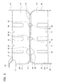
- Fig. 1 is a plan view of an impact absorbing member 10 of the present embodiment.
- Fig. 2 is a side view of the impact absorbing member 10.
- Fig. 3 is a cross-sectional view along the cross-section III-III of Fig. 1 .
- the impact absorbing member 10 is attached to front and rear ends of a vehicle such as an automobile.
- the impact absorbing member 10 attached to a front side of a vehicle will be described.
- the impact absorbing member 10 comprises a tube wall 18 and flange members 16.
- the tube wall 18 is configured as a square tube.
- the flange members 16 extend outward from an outer circumference of the tube wall 18.
- the flange members 16 also extend in an axial direction of the tube wall 18.
- the impact absorbing member 10 comprises a first main body 17 and a second main body 60.
- the first main body 17 comprises a first partial tube wall 19 and first flange members 20, 21.
- the first partial tube wall 19 includes an upper wall 19a and two first side walls 19b.
- the first side walls 19b extend downward from left and right ends of the upper wall 19a (ends located along a direction perpendicular to the axial direction of the tube wall 18).
- the first partial tube wall 19 forms an upper half of the tube wall 18.
- An upper flange member 12 and a front flange member 14 are formed at a front end (the front end in a vehicle's direction of movement) in an axial direction of the first partial tube wall 19.
- the upper flange member 12 and front flange member 14 is connected to a front bumper 2 of the vehicle.
- the upper flange member 12 is connected to an upper surface of a front bumper 2.
- the upper flange member 12 is joined to the front bumper 2 by spot welding.
- the front flange member 14 is connected to a rear surface of the front bumper 2.
- the front flange member 14 is joined to the front bumper 2 by spot welding.
- a rear flange member 54 is formed at a rear end of the first partial tube wall 19 (the rear end in the vehicle's direction of movement).
- the rear flange member 54 is connected to a main body of the vehicle, e.g. a side member.
- the rear flange member 54 is joined to the main body of the vehicle by spot welding.
- Two upper grooves 34 which are concaved towards their lower side are formed in the upper wall 19a of the first partial tube wall 19.
- the two upper grooves 34 are mutually parallel with a space between the two in the axial direction of the tube wall 18.
- Each of the upper grooves 34 is perpendicular to the axial direction of the tube wall 18.
- Each of the upper grooves 34 is formed across the entire width of the upper wall 19a in a widthwise direction (the direction perpendicular to the axial direction of the tube wall 18).
- an upper vertical groove 26 is formed in front of the upper grooves 34 located at the front. The upper vertical grooves 26 are concaved towards an inner side of the tube wall 18.
- Each of the upper vertical grooves 26 is formed at the same location relative to the axial direction of the tube wall 18.
- the upper vertical grooves 26 extend downward from upper ends of the first side walls 19b. Lower ends of the upper vertical grooves 26 are located above lower ends of the first side walls 19b.
- An upper vertical groove 40 is formed between the two upper grooves 34 in each of the first side walls 19b.
- the upper vertical grooves 40 are concaved towards the inner side of the tube wall 18.
- the upper vertical grooves 40 are parallel to the upper vertical grooves 26.
- the length of the upper vertical groove 40 in a vertical direction is approximately the same as the length of the upper vertical groove 26 in a vertical direction.
- the width and depth of the upper vertical groove 40 is greater than that of the upper vertical groove 26.
- an upper vertical groove 48 is formed to the rear of the upper grooves 34 located at the rear.
- the upper vertical grooves 48 are parallel to the upper vertical grooves 26.
- the length of the upper vertical groove 48 in a vertical direction is approximately the same as the length of the upper vertical groove 26 in the vertical direction.
- the width and depth of the upper vertical groove 48 is approximately the same as those of the upper vertical groove 40.
- the first flange member 20 is formed at a lower end of one of the first side walls 19b.
- the first flange member 20 extends toward the outer side of the tube wall 18. Further, the first flange member 20 extends along the axial direction of the tube wall 18.
- the first flange member 21 is formed at a lower end of the other of the first side walls 19b. The first flange member 21 extends toward the outer side of the tube wall 18. Further, the first flange member 21 extends along the axial direction of the tube wall 18.
- the first flange member 21 is longer than the first flange member 20 in the axial direction of the tube wall 18.
- first flange member 21 has approximately the same length as the first flange member 20 in the direction perpendicular to the axial direction of the tube wall 18. Front ends of the first flange members 20, 21 connect to the front flange member 14. Rear ends of the first flange members 20, 21 connect to the rear flange member 54.
- An upper first bead 28 is formed on the first flange member 21 below the upper vertical groove 26.
- the upper first bead 28 is cross-sectionally triangular in the axial direction of the tube wall 18. As shown in Fig. 3 , the height of the upper first bead 28 gradually decreases from an end of the upper first bead 28 at the first side wall 19b side of the first flange member 21 toward the outer side of the first tube wall 18.
- An upper second bead 24 is formed on the first flange member 20 below the upper vertical groove 26.
- the upper second bead 24 is formed in the same location as the upper first bead 28 in the axial direction of the tube wall 18.
- the upper second bead 24 is cross-sectionally triangular in the axial direction of the tube wall 18.
- the height of the upper second bead 24 gradually decreases from an end of the upper second bead 24 at the first side wall 19b side of the first flange member 20 toward the outer side of the first tube wall 18.
- the dimensions of the upper second bead 24 are smaller than those of the upper first bead 28.
- An upper third bead 38 is formed on each of the first flange members 20, 21 below the upper vertical groove 40.
- the upper third bead 38 is cross-sectionally triangular in the axial direction of the tube wall 18.
- the height of the upper third bead 38 gradually decreases from an end of the upper third bead 38 at the first side wall 19b side of the first flange members 20, 21 toward the outer side of the first tube wall 18.
- the upper third beads 38 are formed in the same location in the axial direction of the tube wall 18. Further, the upper third beads 38 have the same shape and dimensions. The dimensions of the upper third bead 38 are smaller than those of the upper second bead 24.
- An upper fourth bead 46 is formed on each of the first flange members 20, 21 below the upper vertical groove 48.
- the upper fourth bead 46 is cross-sectionally triangular in the axial direction of the tube wall 18.
- the height of the upper fourth bead 46 gradually decreases from an end of the upper fourth beads 46 at the first side wall 19b side of the first flange members 20, 21 toward the outer side of the first tube wall 18.
- the upper fourth beads 46 are formed in the same location in the axial direction of the tube wall 18. Further, the upper fourth beads 46 have the same shape and dimensions.
- the dimensions of the upper fourth beads 46 are smaller than those of the upper third beads 38.
- the dimensions of the upper fourth beads 46 may be the same as those of the upper third beads 38.
- the second main body 60 is disposed below the first main body 17.
- the second main body 60 comprises a second partial tube wall 62 and second flange members 64, 66.
- the second partial tube wall 62 is composed of a lower wall 62a and two second side walls 62b.
- the second side walls 62b extend upward from left and right ends of the lower wall 62a.
- the second partial tube wall 62 forms a lower half of the tube wall 18.
- the square tube is composed of the first partial tube wall 19 and the second partial tube wall 62 of the tube wall 18.
- a front flange member 61 connected to the front bumper 2 is formed at a front side of the second partial tube wall 62.
- the front flange member 61 is connected to the rear surface of the front bumper 2.
- the front flange member 61 is joined to the front bumper 2 by spot welding.
- a rear flange member 82 is formed at a rear end of the second partial tube wall 62.
- the rear flange member 82 is connected to the main body of the vehicle.
- the rear flange member 82 is joined to the main body of the vehicle by spot welding.
- Two lower grooves 71 which are concaved towards their upper side are formed in the lower wall 62a of the second partial tube wall 62.
- the two lower grooves 71 are mutually parallel with a space between the two in the axial direction of the tube wall 18.
- Each of the lower grooves 71 is perpendicular to the axial direction of the tube wall 18.
- Each of the lower grooves 71 is formed across the entire width of the lower wall 62a in the widthwise direction.
- Each of the lower groove 71 faces the respective upper groove 34 formed in the upper wall 19a.
- a lower vertical groove 70 is formed in front of the lower groove 71 located at the front. The lower vertical grooves 70 are concaved towards the inner side of the tube wall 18.
- the lower vertical grooves 70 formed in the second side walls 62b are formed at the same location relative to the axial direction of the tube wall 18. Further, each of the lower vertical grooves 70 is formed at a location corresponding to the respective upper vertical groove 26 formed in the first side walls 19b.
- the lower vertical grooves 70 extend upward from lower ends of the second side walls 62b. Upper ends of the lower vertical grooves 70 are located below upper ends of the second side walls 62b.
- the lower vertical grooves 70 have approximately the same width, depth, and length in the vertical direction as the upper vertical grooves 26.
- a lower vertical groove 76 is formed between the two lower grooves 71 in each of the second side walls 62b.
- the lower vertical grooves 76 are concaved towards the inner side of the tube wall 18.
- the lower vertical grooves 76 are formed parallel to the lower vertical grooves 70.
- Each of the lower vertical grooves 76 formed in the second side walls 62b is formed at the same location relative to the axial direction of the tube wall 18. Further, each of the lower vertical grooves 76 is formed at a location corresponding to the upper vertical groove 40 formed in the first side wall 19b.
- the lower vertical grooves 76 extend upward from lower ends of the second side walls 62b. The length of the lower vertical grooves 76 in the vertical direction is approximately the same as that of the lower vertical grooves 70.
- the width and depth of the lower vertical grooves 76 are greater than those of the lower vertical grooves 70, and are approximately the same as those of the upper vertical grooves 40.
- a lower vertical groove 80 is formed in each of the second side walls 62b at a rear side of the lower grooves 71 located at the rear.
- the lower vertical grooves 80 are concaved towards the inner side of the tube wall 18.
- the lower vertical grooves 80 are parallel to the lower vertical grooves 70.
- the lower vertical grooves 80 formed in the second side walls 62b are formed at the same location relative to the axial direction of the tube wall 18. Further, each of the lower vertical grooves 80 is formed at a location corresponding to the respective upper vertical groove 48 formed in the first side walls 19b.
- the lower vertical grooves 80 extend upward from lower ends of the second side walls 62b.
- the length of the lower vertical grooves 80 is approximately the same as that of the lower vertical grooves 70.
- the width and depth of the lower vertical grooves 80 are approximately the same as those of the upper vertical grooves 48.
- the second flange member 64 is formed at an upper end of one of the second side walls 62b.
- the second flange member 64 extends toward the outer side of the tube wall 18. Further, the second flange member 64 extends along the axial direction of the tube wall 18.
- the second flange member 64 faces the first flange member 21.
- the second flange member 66 is formed at an upper end of the other of the second side walls 62b.
- the second flange member 66 extends toward the outer side of the tube wall 18. Further, the second flange member 66 extends along the axial direction of the tube wall 18.
- the second flange member 66 faces the first flange member 20.
- the second flange member 64 is longer than the second flange member 66.
- the second flange member 64 has approximately the same length as the first flange member 21 in the axial direction of the tube wall 18.
- the second flange member 66 has approximately the same length as the first flange member 21 in the axial direction of the tube wall 18. Further, the second flange member 64 has approximately the same length as the second flange member 66 and the first flange member 21 in the direction perpendicular to the axial direction of the tube wall 18. Front ends of the second flange members 64, 66 connect to the front flange member 61. Rear ends of the second flange members 64, 66 connect to the rear flange member 82.
- a lower first bead 68 is formed on the second flange member 64 above the lower vertical groove 70.
- the lower first bead 68 is formed below the upper first bead 28.
- the lower first bead 68 has shape and dimensions symmetric to those of the upper first bead 28, with respect to a boundary X (see Fig. 3 ) between the first main body 17 and the second main body 60.
- the upper first bead 28 and lower first bead 68 form a space between a first side wall 19b side end part of the first flange member 21 and a second side wall 62b side end part of the second flange member 64.
- a lower second bead 72 is formed on the second flange member 66 above the lower vertical groove 70.
- the lower second bead 72 is formed below the upper second bead 24.
- the lower second bead 72 has a shape and dimensions symmetric to those of the upper second bead 24, with respect to the boundary X.
- the upper second bead 24 and lower second bead 72 form a space between a first side wall 19b side end part of the first flange member 20 and a second side wall 62b side end part of the second flange member 66.
- a lower third bead 74 is formed on each of the second flange members 64, 66 above the lower vertical groove 76. Each of the lower third beads 74 is formed below the respective upper third bead 38.
- the lower third bead 74 has a shape and dimensions symmetric to those of the upper third bead 38, with respect to the boundary X.
- the upper third bead 38 and lower third bead 74 form a space between a first side wall 19b side end part of the first flange member 21 and a second side wall 62b side end part of the second flange member 64. Further, the upper third bead 38 and lower third bead 74 form a space between the first side wall 19b side end part of the first flange member 20 and the second side wall 62b side end part of the second flange member 66.
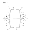
- Fig. 4 is a cross-sectional view along the cross-section IV-IV of Fig. 1 .
- a lower fourth bead 78 is formed on each of the second flange members 64, 66 above the lower vertical groove 80.
- Each of the lower fourth beads 78 is formed below the respective upper fourth bead 46.
- the lower fourth bead 78 has a shape and dimensions symmetric to those of the fourth bead 46, with respect to the boundary X.
- the upper fourth bead 46 and lower fourth bead 78 form a space between a first side wall 19b side end part of the first flange member 21 and a second side wall 62b side end part of the second flange member 64.
- the upper fourth bead 46 and the lower fourth bead 78 form a space between the first side wall 19b side end part of the first flange member 20 and the second side wall 62b side end part of the second flange member 66.
- the dimensions of the beads 68, 72, 74, 78 become smaller in the order of: the lower first bead 68, the lower second bead 72, the lower third bead 74, the lower fourth bead 78.
- the dimensions of the lower third bead 74 may be the same as those of the lower fourth bead 78.
- the first flange member 21 and second flange member 64 are joined by four joining points 36 by spot welding.
- the joining points 36 are located, in the axial direction of the tube wall 18, at a front end part of the first flange member 21, between the first beads 28, 68 and the third beads 38, 74, between the third beads 38, 74 and the fourth beads 46, 78, and at a rear end part of the first flange member 21.
- the beads 28, 38, 46, 68, 74, 78 are formed, in the axial direction of the tube wall 18, in the sections where the first flange member 21 and the second flange member 64 are not joined; i.e., the spaces between the first side wall 19b side end parts of the first flange member 21 and the second side wall 62b side end parts of the second flange member 64 are formed in the sections where the first flange member 21 and the second flange member 64 are not joined. Further, the joining points 36 located between the beads are at the same location as the upper grooves 34 (lower grooves 71) in the axial direction of the tube wall 18.
- the first flange member 20 and the second flange member 66 are joined by three joining points 36 by spot welding.
- the joining points 36 are located between the second beads 24, 72 and the third beads 38, 74, between the third beads 38, 74 and the fourth beads 46, 78, and at a rear end part of the first flange member 20.
- the beads 28, 38, 46, 68, 74, 78 are formed, in the axial direction of the tube wall 18, in the sections where the first flange member 20 and the second flange member 66 are not joined.
- the spaces between the first side wall 19b side end parts of the first flange member 20 and the second side wall 62b side end parts of the second flange member 66 are formed in the sections where the first flange member 20 and the second flange member 66 are not joined. Further, the joining points 36 located between the beads are at the same location as the upper grooves 34 (lower grooves 71) in the axial direction of the tube wall 18.
- the impact absorbing member 10 absorbs the impact energy as a result of the impact absorbing member 10 deforming compressively in the axial direction of the tube wall 18. Because the upper vertical grooves 26, 70 are concaved to the inner side of the tube wall 18, the space formed by the first beads 28, 68 deforms in a closing direction during an initial application of compressive load to the impact absorbing member 10. Consequently, the outer end parts of the first flange member 21 and second flange member 64 mutually separate at the location where the space is formed (the location where the first beads 28, 68 are formed).
- the space formed by the second beads 24, 72 deforms in a closing direction, and the outer end parts of the first flange member 20 and second flange member 66 mutually separate at the location where the space is formed (the location where the second beads 24, 72 are formed).
- the flange members 20, 21, 64, 66 begin to deform at the location where the space is formed. It is thus possible to specify the location where deformation occurs when the compressive load is initially applied to the flange members. In a case where further compressive load is applied from this state, the flange members 20, 21, 64, 66 deform further at the location where deformation had already begun, and they buckle. A similar phenomenon occurs at the locations where the third beads 38, 74 are formed and the fourth beads 46, 78 are formed.
- the load is greatest at the location where the load acts, i.e. the front side of the vehicle.
- the beads 24, 28, 68, 72 that are located at the front end side in the axial direction of the tube wall 18 are larger than the beads located at the rear end side in the axial direction of the tube wall 18. Consequently, in the impact absorbing member 10, the side at the front of the vehicle deforms readily. It is thereby possible to prevent variation between products in the location where deformation of the flange members 16 occurs during the initial application of compressive load.
- the upper vertical grooves 26, 40, 48 are each formed in the first side walls 19b in locations corresponding to the beads 24, 28, 38, 46 formed on the first flange members 20, 21.
- the lower vertical grooves 70, 76, 80 are each formed in the second side walls 62b in locations corresponding to the beads 68, 72, 74, 78 formed on the second flange members 64, 66.
- the upper groove 34 is formed in the upper wall 19a
- the lower groove 71 is formed in the lower wall 62a.
- the upper groove 34 is disposed away from the upper vertical grooves 26, 40, 48 in the axial direction of the tube wall 18.
- the lower groove 71 is disposed away from the lower vertical grooves 70, 76, 80 in the axial direction of the tube wall 18.
- the upper walls 19a, 62a readily deform into a convexing shape toward the outer side of the tube due to the first side walls 19b, 62b being concaved towards the inner side of the tube wall 18. Variation between products in the deformation state or deformation process of compressive deformation of the tube wall 18 can thereby be controlled.
- the upper first bead 28 formed on the first flange member 21 is disposed at the same location as the upper second bead 24 formed on the first flange member 20 relative to the axial direction of the tube wall 18.
- the location of the upper first bead 28 and upper second bead 24 may differ relative to the axial direction of the tube wall 18.
- the beads that are formed at the same location relative to the axial direction of the tube wall 18 on the impact absorbing member 10 may be formed at different locations.
- the joining points 36 of the first flange member 20 and second flange member 66 and the joining points 36 of the first flange member 21 and second flange member 64 are disposed in the same location relative to the axial direction of the tube wall 18.
- the joining points 36 of the first flange member 20 and second flange member 66 and the joining points 36 of the first flange member 21 and second flange member 64 may be disposed in differing locations relative to the axial direction of the tube wall 18.
- a bead 100 may have a semi-conical shape of which a bottom surface is located on the first side wall 19b, and which extends towards an outer side of the first partial tube wall 19.
- a bead 200 may have a semi-conical shape of which a bottom surface is located on the first flange member 21, and which extends along the first side wall 19b.
- Fig. 5 a bead 100 may have a semi-conical shape of which a bottom surface is located on the first side wall 19b, and which extends towards an outer side of the first partial tube wall 19.
- a bead 200 may have a semi-conical shape of which a bottom surface is located on the first flange member 21, and which extends along the first side wall 19b.
- a bead 300 may have a semi-circular shape which extends toward the outer side of the first partial tube wall 19. Further, the shape of all the beads may be identical; alternately, some of the beads may have a differing shape from the other beads. Further, in the impact absorbing member 10, the tube wall 18 forms a square tube. However, the tube formed by the tube wall need not be square. It may, e.g., be round, or a polygonal shape other than square: e.g., hexagonal, octagonal, etc.
Landscapes
- Engineering & Computer Science (AREA)
- Mechanical Engineering (AREA)
- General Engineering & Computer Science (AREA)
- Body Structure For Vehicles (AREA)
- Refuge Islands, Traffic Blockers, Or Guard Fence (AREA)
- Vibration Dampers (AREA)
Abstract
Description
- The present invention relates to an impact absorbing member used by being attached to a vehicle, which deforms compressively in an axial direction and absorbs impact energy during collision of the vehicle.
- Patent Document 1 discloses an impact absorbing member comprising a tube wall that configures a tube, and flange members extending outward from an outer circumference of the tube wall and also extending in an axial direction of the tube. In a case where this impact absorbing member is subjected to a compressive load in the axial direction upon collision of the vehicle, the tube wall and flange members deform compressively along the axial direction by buckling. This impact absorbing member comprises a first main body and a second main body. Each of the first main body and second main body comprises a partial tube wall in which the tube wall is divided in a circumferential direction, and flange members extending toward the outer side of the tube from both ends in the circumferential direction of the partial tube wall, and also extending in the axial direction of the tube. The impact absorbing member is formed by joining the flange members of the first main body and the flange members of the second main body. The flange members of the first main body and the flange members of the second main body make contact across their entire surfaces.
- Patent Document 1: Japanese Patent Application Publication No.
2000-81069 - In the impact absorbing member of Patent Document 1 cited above, the deformation process during compressive deformation (e.g. a location where buckling occurs or a state during deformation) is not constant. Consequently, the deformation process is not necessarily the same even if the impact absorbing members are manufactured in the same shape. As a result, the relationship between the compressive load on the impact absorbing member and the degree of compressive deformation is not constant, and a large variation between products ensues.
- The present invention was made in light of the circumstances described above, and aims to present, in an impact absorbing member comprising a tube wall and flange members, a technique that reduces variation between products in the relationship between the compressive load on the impact absorbing member and the degree of compressive deformation.
- The impact absorbing member of the present invention comprises a tube wall and flange members. The tube wall composes a tube. The flange members extend outward from an outer circumference of the tube wall and also extend in an axial direction of the tube. One end of the impact absorbing member in the axial direction is attached to a main body of a vehicle. Upon collision of the vehicle, the tube wall and the flange members of the impact absorbing member are deformed compressively along the axial direction.
The impact absorbing member of the present invention comprises at least a first main body and a second main body. The first main body comprises a first partial tube wall and first flange members. The first partial tube wall composes a partial tube wall dividing the tube wall in a circumferential direction. The first flange members extend toward an outer side of the tube from both ends in a circumferential direction of the first partial tube wall, and also extend in the axial direction of the tube. The second main body comprises a second partial tube wall and second flange members. The second partial tube wall composes a partial tube wall dividing the tube wall in a circumferential direction. The second flange members extend toward the outer side of the tube from both ends in a circumferential direction of the second partial tube wall, and also extend in the axial direction of the tube. The first flange members and the second flange members are joined intermittently in the axial direction of the tube. At least one of sections where the first flange members and the second flange members are not joined in the axial direction of the tube, a space is formed between a first partial tube wall side end part of the first flange members and a second partial tube wall side end part of the second flange members. - To reduce variation in the relationship between the compressive load on the impact absorbing member and the degree of compressive deformation, it is important to reduce variation in the deformation state and the buckling location of the flange member. In this impact absorbing member, a space is formed at a predetermined location in the axial direction between the first partial tube wall side end part of the first flange members and the second partial tube wall side end part of the second flange members. The first flange members and the second flange members are not joined at the location where this space is formed. When a compressive load is applied in the axial direction of the impact absorbing member, the tube wall deforms so that the space formed between the first partial tube wall side end part of the first flange members and the second partial tube wall side end part of the second flange members closes in an axial direction of a tube body and in a circumferential direction of the tube body. An outer end part of the first flange member and an outer end part of the second flange member thereby move away from each other in the location where the space is formed, and the outer end part of the first flange member and the outer end part of the second flange member deform in an opening direction. The first flange member and second flange member thereby begin to deform at the same location (the location where the space is formed). In a case where further compressive load is applied from this state, further deformation occurs at the location where deformation had already started, and both the flange member buckle and are compressed in the axial direction of the tube.
According to this impact absorbing member, buckling progresses in sequence at the location where the space is formed. Junction points between the first flange memebers and second flange members remain in the same plane before and after buckling; i.e., the deformation process of the impact absorbing member is stabilized.
According to this impact absorbing member, variation between products in the location where buckling of the flange members occurs and variation in the deformation state or deformation process can be reduced. Variation between products in the relationship between the compressive load on the impact absorbing member and the degree of compressive deformation may thereby be reduced. - In this impact absorbing member, it is preferred that one space is formed in each of the sections where the first flange members and the second flange members are not joined in the axial direction of the tube. It is preferred that a space located furthest from the main body of the vehicle is larger than the other spaces.
In the impact absorbing member, during an initial stage of the application of the compressive load, a large load is applied close to a location where the load is acting, i.e. a location furthest from the main body of the vehicle. In this impact absorbing member, the space furthest from the main body of the vehicle may be larger than the other spaces. Consequently, the space furthest from the main body of the vehicle yields to deformation more easily than the other spaces. Variation in the deformation location of the flange members during initial application of the compressive load may thereby be reduced. Consequently, variation between products in the relationship between the compressive load on the impact absorbing member and the degree of compressive deformation may reliably be reduced. - In this impact absorbing member, it is preferred that the spaces become smaller as they become more distant from the tube wall.
According to this configuration, the outer end part of the first flange member and the outer end part of the second flange member easily move apart; i.e., the first flange member and the second flange member easily deform at the location where the space is formed. The flange members may thereby be more reliably made to deform at the desired location. - According to the present invention, variation between impact absorbing members in the relationship between the compressive load on the impact absorbing member and the degree of compressive deformation can be reduced. Variation in the impact energy absorption performance of the impact absorbing members between products can thereby be reduced.
-
-
Fig. 1 is a plan view of an impact absorbing member of a present embodiment. -
Fig. 2 is a side view of the impact absorbing member of the present embodiment. -
Fig. 3 is a cross-sectional view along the cross-section III-III ofFig. 1 . -
Fig. 4 is a cross-sectional view along the cross-section IV-IV ofFig. 1 . -
Fig. 5 is a perspective view of a part of a variant of the impact absorbing member. -
Fig. 6 is a perspective view of a part of a variant of the impact absorbing member. -
Fig. 7 is a perspective view of a part of a variant of the impact absorbing member. - Some technical features of the present invention are listed below. (First feature) The impact absorbing member may further comprise a third main body in addition to the first main body and second main body. In this case, the third main body may comprise a third partial tube wall configuring a partial tube wall in which a tube wall is divided in a circumferential direction, and a pair of third flange members formed at each of both ends in the circumferential direction of the third partial tube wall.
In this case, second flange members may join with first flange members. Third flange members may join with the second flange members. The first flange members may join with the third flange members. A tube may be composed of the first partial tube wall, second partial tube wall, and third partial tube wall.
(Second feature) A fourth main body, fifth main body, etc. may be provided. The number of members constituting the tube wall may be varied as desired.
(Third feature) In a case where there are three members constituting the tube wall, the first flange members and third flange members may be joined intermittently in the axial direction of the tube. The second flange members and third flange members may be joined intermittently in the axial direction of the tube. In a part of a section where the first flange members and third flange members are not joined in the axial direction of the tube, a space may be formed between the first partial tube wall side end part of the first flange members and the third partial tube wall side end part of the third flange members. In a part of a section where the second flange member and third flange member are not joined in the axial direction of the tube, a space may be formed between the second partial tube wall side end part of the second flange member and the third partial tube wall side end part of the third flange member. According to this configuration, variation between impact absorbing members in the relationship between the compressive load on the impact absorbing member and the degree of compressive deformation can be reduced.
(Fourth feature) One space between the first flange member and second flange member (the space between a pair of joined flange members) may be formed for each of non-joined sections, or two or more spaces per such sections may be formed. Further, the number of spaces per section may differ among the sections. Further, sections without a space may be present. According to these configurations as well, variation between impact absorbing members in the relationship between the compressive load on the impact absorbing member and the degree of compressive deformation can be reduced. - An impact absorbing member of the present embodiment in which the present invention may be realized will be explained with reference to the figures.
Fig. 1 is a plan view of animpact absorbing member 10 of the present embodiment.Fig. 2 is a side view of theimpact absorbing member 10.Fig. 3 is a cross-sectional view along the cross-section III-III ofFig. 1 .
For example, theimpact absorbing member 10 is attached to front and rear ends of a vehicle such as an automobile. In the present embodiment, theimpact absorbing member 10 attached to a front side of a vehicle will be described.
As shown inFigs. 1 ,2 and3 , theimpact absorbing member 10 comprises atube wall 18 andflange members 16. Thetube wall 18 is configured as a square tube. Theflange members 16 extend outward from an outer circumference of thetube wall 18. Theflange members 16 also extend in an axial direction of thetube wall 18.
Theimpact absorbing member 10 comprises a firstmain body 17 and a secondmain body 60. - The first
main body 17 comprises a firstpartial tube wall 19 andfirst flange members partial tube wall 19 includes anupper wall 19a and twofirst side walls 19b. Thefirst side walls 19b extend downward from left and right ends of theupper wall 19a (ends located along a direction perpendicular to the axial direction of the tube wall 18). The firstpartial tube wall 19 forms an upper half of thetube wall 18. Anupper flange member 12 and afront flange member 14 are formed at a front end (the front end in a vehicle's direction of movement) in an axial direction of the firstpartial tube wall 19. Theupper flange member 12 andfront flange member 14 is connected to afront bumper 2 of the vehicle. Theupper flange member 12 is connected to an upper surface of afront bumper 2. Theupper flange member 12 is joined to thefront bumper 2 by spot welding. Thefront flange member 14 is connected to a rear surface of thefront bumper 2. Thefront flange member 14 is joined to thefront bumper 2 by spot welding. Arear flange member 54 is formed at a rear end of the first partial tube wall 19 (the rear end in the vehicle's direction of movement). Therear flange member 54 is connected to a main body of the vehicle, e.g. a side member. Therear flange member 54 is joined to the main body of the vehicle by spot welding. - Two
upper grooves 34 which are concaved towards their lower side are formed in theupper wall 19a of the firstpartial tube wall 19. The twoupper grooves 34 are mutually parallel with a space between the two in the axial direction of thetube wall 18. Each of theupper grooves 34 is perpendicular to the axial direction of thetube wall 18. Each of theupper grooves 34 is formed across the entire width of theupper wall 19a in a widthwise direction (the direction perpendicular to the axial direction of the tube wall 18).
In each of thefirst side walls 19b, an uppervertical groove 26 is formed in front of theupper grooves 34 located at the front. The uppervertical grooves 26 are concaved towards an inner side of thetube wall 18. Each of the uppervertical grooves 26 is formed at the same location relative to the axial direction of thetube wall 18. The uppervertical grooves 26 extend downward from upper ends of thefirst side walls 19b. Lower ends of the uppervertical grooves 26 are located above lower ends of thefirst side walls 19b. An uppervertical groove 40 is formed between the twoupper grooves 34 in each of thefirst side walls 19b. The uppervertical grooves 40 are concaved towards the inner side of thetube wall 18. The uppervertical grooves 40 are parallel to the uppervertical grooves 26. The length of the uppervertical groove 40 in a vertical direction is approximately the same as the length of the uppervertical groove 26 in a vertical direction. The width and depth of the uppervertical groove 40 is greater than that of the uppervertical groove 26. Further, in each of thefirst side walls 19b, an uppervertical groove 48 is formed to the rear of theupper grooves 34 located at the rear. The uppervertical grooves 48 are parallel to the uppervertical grooves 26. The length of the uppervertical groove 48 in a vertical direction is approximately the same as the length of the uppervertical groove 26 in the vertical direction. The width and depth of the uppervertical groove 48 is approximately the same as those of the uppervertical groove 40. - The
first flange member 20 is formed at a lower end of one of thefirst side walls 19b. Thefirst flange member 20 extends toward the outer side of thetube wall 18. Further, thefirst flange member 20 extends along the axial direction of thetube wall 18. Thefirst flange member 21 is formed at a lower end of the other of thefirst side walls 19b. Thefirst flange member 21 extends toward the outer side of thetube wall 18. Further, thefirst flange member 21 extends along the axial direction of thetube wall 18. Thefirst flange member 21 is longer than thefirst flange member 20 in the axial direction of thetube wall 18. Further, thefirst flange member 21 has approximately the same length as thefirst flange member 20 in the direction perpendicular to the axial direction of thetube wall 18. Front ends of thefirst flange members front flange member 14. Rear ends of thefirst flange members rear flange member 54. - An upper
first bead 28 is formed on thefirst flange member 21 below the uppervertical groove 26. The upperfirst bead 28 is cross-sectionally triangular in the axial direction of thetube wall 18. As shown inFig. 3 , the height of the upperfirst bead 28 gradually decreases from an end of the upperfirst bead 28 at thefirst side wall 19b side of thefirst flange member 21 toward the outer side of thefirst tube wall 18. An uppersecond bead 24 is formed on thefirst flange member 20 below the uppervertical groove 26. The uppersecond bead 24 is formed in the same location as the upperfirst bead 28 in the axial direction of thetube wall 18. The uppersecond bead 24 is cross-sectionally triangular in the axial direction of thetube wall 18. As shown inFig. 3 , the height of the uppersecond bead 24 gradually decreases from an end of the uppersecond bead 24 at thefirst side wall 19b side of thefirst flange member 20 toward the outer side of thefirst tube wall 18. The dimensions of the upper second bead 24 (height in the vertical direction, width in the axial direction of thetube wall 18, length in the direction perpendicular to the axial direction of the tube wall 18) are smaller than those of the upperfirst bead 28. - An upper
third bead 38 is formed on each of thefirst flange members vertical groove 40. The upperthird bead 38 is cross-sectionally triangular in the axial direction of thetube wall 18. The height of the upperthird bead 38 gradually decreases from an end of the upperthird bead 38 at thefirst side wall 19b side of thefirst flange members first tube wall 18. The upperthird beads 38 are formed in the same location in the axial direction of thetube wall 18. Further, the upperthird beads 38 have the same shape and dimensions. The dimensions of the upperthird bead 38 are smaller than those of the uppersecond bead 24. - An upper
fourth bead 46 is formed on each of thefirst flange members vertical groove 48. The upperfourth bead 46 is cross-sectionally triangular in the axial direction of thetube wall 18. The height of the upperfourth bead 46 gradually decreases from an end of the upperfourth beads 46 at thefirst side wall 19b side of thefirst flange members first tube wall 18. The upperfourth beads 46 are formed in the same location in the axial direction of thetube wall 18. Further, the upperfourth beads 46 have the same shape and dimensions. The dimensions of the upperfourth beads 46 are smaller than those of the upperthird beads 38. The dimensions of the upperfourth beads 46 may be the same as those of the upperthird beads 38. - As shown in
Fig. 2 , the secondmain body 60 is disposed below the firstmain body 17. As shown inFig. 3 , the secondmain body 60 comprises a secondpartial tube wall 62 andsecond flange members partial tube wall 62 is composed of alower wall 62a and twosecond side walls 62b. Thesecond side walls 62b extend upward from left and right ends of thelower wall 62a. The secondpartial tube wall 62 forms a lower half of thetube wall 18. The square tube is composed of the firstpartial tube wall 19 and the secondpartial tube wall 62 of thetube wall 18. As shown inFig. 2 , afront flange member 61 connected to thefront bumper 2 is formed at a front side of the secondpartial tube wall 62. Thefront flange member 61 is connected to the rear surface of thefront bumper 2. Thefront flange member 61 is joined to thefront bumper 2 by spot welding. Arear flange member 82 is formed at a rear end of the secondpartial tube wall 62. Therear flange member 82 is connected to the main body of the vehicle. Therear flange member 82 is joined to the main body of the vehicle by spot welding. - Two
lower grooves 71 which are concaved towards their upper side are formed in thelower wall 62a of the secondpartial tube wall 62. The twolower grooves 71 are mutually parallel with a space between the two in the axial direction of thetube wall 18. Each of thelower grooves 71 is perpendicular to the axial direction of thetube wall 18. Each of thelower grooves 71 is formed across the entire width of thelower wall 62a in the widthwise direction. Each of thelower groove 71 faces the respectiveupper groove 34 formed in theupper wall 19a.
In each of thesecond side walls 62b, a lowervertical groove 70 is formed in front of thelower groove 71 located at the front. The lowervertical grooves 70 are concaved towards the inner side of thetube wall 18. The lowervertical grooves 70 formed in thesecond side walls 62b are formed at the same location relative to the axial direction of thetube wall 18. Further, each of the lowervertical grooves 70 is formed at a location corresponding to the respective uppervertical groove 26 formed in thefirst side walls 19b. The lowervertical grooves 70 extend upward from lower ends of thesecond side walls 62b. Upper ends of the lowervertical grooves 70 are located below upper ends of thesecond side walls 62b. The lowervertical grooves 70 have approximately the same width, depth, and length in the vertical direction as the uppervertical grooves 26. - A lower
vertical groove 76 is formed between the twolower grooves 71 in each of thesecond side walls 62b. The lowervertical grooves 76 are concaved towards the inner side of thetube wall 18. The lowervertical grooves 76 are formed parallel to the lowervertical grooves 70. Each of the lowervertical grooves 76 formed in thesecond side walls 62b is formed at the same location relative to the axial direction of thetube wall 18. Further, each of the lowervertical grooves 76 is formed at a location corresponding to the uppervertical groove 40 formed in thefirst side wall 19b. The lowervertical grooves 76 extend upward from lower ends of thesecond side walls 62b. The length of the lowervertical grooves 76 in the vertical direction is approximately the same as that of the lowervertical grooves 70. The width and depth of the lowervertical grooves 76 are greater than those of the lowervertical grooves 70, and are approximately the same as those of the uppervertical grooves 40. Further, a lowervertical groove 80 is formed in each of thesecond side walls 62b at a rear side of thelower grooves 71 located at the rear. The lowervertical grooves 80 are concaved towards the inner side of thetube wall 18. The lowervertical grooves 80 are parallel to the lowervertical grooves 70. The lowervertical grooves 80 formed in thesecond side walls 62b are formed at the same location relative to the axial direction of thetube wall 18. Further, each of the lowervertical grooves 80 is formed at a location corresponding to the respective uppervertical groove 48 formed in thefirst side walls 19b. The lowervertical grooves 80 extend upward from lower ends of thesecond side walls 62b. The length of the lowervertical grooves 80 is approximately the same as that of the lowervertical grooves 70. The width and depth of the lowervertical grooves 80 are approximately the same as those of the uppervertical grooves 48. - The
second flange member 64 is formed at an upper end of one of thesecond side walls 62b. Thesecond flange member 64 extends toward the outer side of thetube wall 18. Further, thesecond flange member 64 extends along the axial direction of thetube wall 18. Thesecond flange member 64 faces thefirst flange member 21. Thesecond flange member 66 is formed at an upper end of the other of thesecond side walls 62b. Thesecond flange member 66 extends toward the outer side of thetube wall 18. Further, thesecond flange member 66 extends along the axial direction of thetube wall 18. Thesecond flange member 66 faces thefirst flange member 20. Thesecond flange member 64 is longer than thesecond flange member 66. Thesecond flange member 64 has approximately the same length as thefirst flange member 21 in the axial direction of thetube wall 18. Thesecond flange member 66 has approximately the same length as thefirst flange member 21 in the axial direction of thetube wall 18. Further, thesecond flange member 64 has approximately the same length as thesecond flange member 66 and thefirst flange member 21 in the direction perpendicular to the axial direction of thetube wall 18. Front ends of thesecond flange members front flange member 61. Rear ends of thesecond flange members rear flange member 82. - A lower
first bead 68 is formed on thesecond flange member 64 above the lowervertical groove 70. The lowerfirst bead 68 is formed below the upperfirst bead 28. The lowerfirst bead 68 has shape and dimensions symmetric to those of the upperfirst bead 28, with respect to a boundary X (seeFig. 3 ) between the firstmain body 17 and the secondmain body 60. The upperfirst bead 28 and lowerfirst bead 68 form a space between afirst side wall 19b side end part of thefirst flange member 21 and asecond side wall 62b side end part of thesecond flange member 64.
A lowersecond bead 72 is formed on thesecond flange member 66 above the lowervertical groove 70. The lowersecond bead 72 is formed below the uppersecond bead 24. The lowersecond bead 72 has a shape and dimensions symmetric to those of the uppersecond bead 24, with respect to the boundary X. The uppersecond bead 24 and lowersecond bead 72 form a space between afirst side wall 19b side end part of thefirst flange member 20 and asecond side wall 62b side end part of thesecond flange member 66. - A lower
third bead 74 is formed on each of thesecond flange members vertical groove 76. Each of the lowerthird beads 74 is formed below the respective upperthird bead 38. The lowerthird bead 74 has a shape and dimensions symmetric to those of the upperthird bead 38, with respect to the boundary X. The upperthird bead 38 and lowerthird bead 74 form a space between afirst side wall 19b side end part of thefirst flange member 21 and asecond side wall 62b side end part of thesecond flange member 64. Further, the upperthird bead 38 and lowerthird bead 74 form a space between thefirst side wall 19b side end part of thefirst flange member 20 and thesecond side wall 62b side end part of thesecond flange member 66. -
Fig. 4 is a cross-sectional view along the cross-section IV-IV ofFig. 1 . As shown inFig. 4 , a lowerfourth bead 78 is formed on each of thesecond flange members vertical groove 80. Each of the lowerfourth beads 78 is formed below the respective upperfourth bead 46. The lowerfourth bead 78 has a shape and dimensions symmetric to those of thefourth bead 46, with respect to the boundary X. The upperfourth bead 46 and lowerfourth bead 78 form a space between afirst side wall 19b side end part of thefirst flange member 21 and asecond side wall 62b side end part of thesecond flange member 64. Further, the upperfourth bead 46 and the lowerfourth bead 78 form a space between thefirst side wall 19b side end part of thefirst flange member 20 and thesecond side wall 62b side end part of thesecond flange member 66.
The dimensions of thebeads first bead 68, the lowersecond bead 72, the lowerthird bead 74, the lowerfourth bead 78. The dimensions of the lowerthird bead 74 may be the same as those of the lowerfourth bead 78. - As shown in
Fig. 1 , thefirst flange member 21 andsecond flange member 64 are joined by four joiningpoints 36 by spot welding. The joining points 36 are located, in the axial direction of thetube wall 18, at a front end part of thefirst flange member 21, between thefirst beads third beads third beads fourth beads first flange member 21. Thebeads tube wall 18, in the sections where thefirst flange member 21 and thesecond flange member 64 are not joined; i.e., the spaces between thefirst side wall 19b side end parts of thefirst flange member 21 and thesecond side wall 62b side end parts of thesecond flange member 64 are formed in the sections where thefirst flange member 21 and thesecond flange member 64 are not joined. Further, the joiningpoints 36 located between the beads are at the same location as the upper grooves 34 (lower grooves 71) in the axial direction of thetube wall 18. - The
first flange member 20 and thesecond flange member 66 are joined by three joiningpoints 36 by spot welding. The joining points 36 are located between thesecond beads third beads third beads fourth beads first flange member 20. Thebeads tube wall 18, in the sections where thefirst flange member 20 and thesecond flange member 66 are not joined. The spaces between thefirst side wall 19b side end parts of thefirst flange member 20 and thesecond side wall 62b side end parts of thesecond flange member 66 are formed in the sections where thefirst flange member 20 and thesecond flange member 66 are not joined. Further, the joiningpoints 36 located between the beads are at the same location as the upper grooves 34 (lower grooves 71) in the axial direction of thetube wall 18. - If an object collides with the front side of the vehicle while the
impact absorbing member 10 is attached to the main body of the vehicle, theimpact absorbing member 10 absorbs the impact energy as a result of theimpact absorbing member 10 deforming compressively in the axial direction of thetube wall 18. Because the uppervertical grooves tube wall 18, the space formed by thefirst beads impact absorbing member 10. Consequently, the outer end parts of thefirst flange member 21 andsecond flange member 64 mutually separate at the location where the space is formed (the location where thefirst beads second beads first flange member 20 andsecond flange member 66 mutually separate at the location where the space is formed (the location where thesecond beads flange members flange members third beads fourth beads flange members points 36 remain in the same plane after buckling as before buckling. Consequently, it is possible to reduce variation between products in the location where buckling of theflange member 17 occurs and in the deformation state or deformation process. It is thereby possible to reduce variation between products in the relationship between the compressive load on theimpact absorbing member 10 and the degree of compressive deformation. - During the initial application of compressive load, the load is greatest at the location where the load acts, i.e. the front side of the vehicle. In the
impact absorbing member 10, thebeads tube wall 18 are larger than the beads located at the rear end side in the axial direction of thetube wall 18. Consequently, in theimpact absorbing member 10, the side at the front of the vehicle deforms readily. It is thereby possible to prevent variation between products in the location where deformation of theflange members 16 occurs during the initial application of compressive load.
Further, in theimpact absorbing member 10, the uppervertical grooves first side walls 19b in locations corresponding to thebeads first flange members vertical grooves second side walls 62b in locations corresponding to thebeads second flange members impact absorbing member 10 is deformed compressively by the compressive load, thefirst side walls tube wall 18 at the locations where the uppervertical grooves vertical grooves impact absorbing member 10 can thereby be controlled. - Further, in the
impact absorbing member 10, theupper groove 34 is formed in theupper wall 19a, and thelower groove 71 is formed in thelower wall 62a. Theupper groove 34 is disposed away from the uppervertical grooves tube wall 18. Thelower groove 71 is disposed away from the lowervertical grooves tube wall 18. When theimpact absorbing member 10 is deformed by a load, theupper wall 19a andlower wall 62a readily deform into a concaving shape towards the inner side of thetube wall 18 at the locations where theupper groove 34 andlower groove 71 are formed. Further, at the locations where the uppervertical grooves upper walls first side walls tube wall 18. Variation between products in the deformation state or deformation process of compressive deformation of thetube wall 18 can thereby be controlled. - Variants of the
impact absorbing member 10 will be listed.
In theimpact absorbing member 10, the upperfirst bead 28 formed on thefirst flange member 21 is disposed at the same location as the uppersecond bead 24 formed on thefirst flange member 20 relative to the axial direction of thetube wall 18. However, the location of the upperfirst bead 28 and uppersecond bead 24 may differ relative to the axial direction of thetube wall 18. Similarly, the beads that are formed at the same location relative to the axial direction of thetube wall 18 on theimpact absorbing member 10 may be formed at different locations.
In theimpact absorbing member 10, the joiningpoints 36 of thefirst flange member 20 andsecond flange member 66 and the joiningpoints 36 of thefirst flange member 21 andsecond flange member 64 are disposed in the same location relative to the axial direction of thetube wall 18. However, the joiningpoints 36 of thefirst flange member 20 andsecond flange member 66 and the joiningpoints 36 of thefirst flange member 21 andsecond flange member 64 may be disposed in differing locations relative to the axial direction of thetube wall 18. - Further, the location, dimensions and shape of the beads may be changed in response to the required amount of strength, deformation, etc. The shape of the bead may be as follows. As exemplified in
Fig. 5 , abead 100 may have a semi-conical shape of which a bottom surface is located on thefirst side wall 19b, and which extends towards an outer side of the firstpartial tube wall 19. Alternatively, e.g., as shown inFig. 6 , abead 200 may have a semi-conical shape of which a bottom surface is located on thefirst flange member 21, and which extends along thefirst side wall 19b. Alternatively, as shown inFig. 7 , abead 300 may have a semi-circular shape which extends toward the outer side of the firstpartial tube wall 19.
Further, the shape of all the beads may be identical; alternately, some of the beads may have a differing shape from the other beads.
Further, in theimpact absorbing member 10, thetube wall 18 forms a square tube. However, the tube formed by the tube wall need not be square. It may, e.g., be round, or a polygonal shape other than square: e.g., hexagonal, octagonal, etc. - A specific example of the present invention is described above in detail, but this merely illustrates some possibilities of the teachings and does not restrict the scope of the claims. The art set forth in the claims includes variations and modifications of the specific example set forth above.
Further, the technical elements disclosed in the specification or the drawings have technical utility separately or in all types of combinations, and are not limited to the combinations set forth in the claims at the time of filing of the application. Furthermore, the art disclosed in the specification or the drawings may be utilized to simultaneously achieve a plurality of aims, and has technical utility by achieving any one of these aims.
Claims (3)
- An impact absorbing member comprising a tube wall composing a tube, and flange members extending outward from an outer circumference of the tube wall and also extending in an axial direction of the tube, wherein one end of the impact absorbing member in the axial direction is attached to a main body of a vehicle, and the tube wall and the flange members are deformed compressively along the axial direction upon collision of the vehicle, the impact absorbing member comprising:at least a first main body and a second main body, whereinthe first main body comprises a first partial tube wall composing a partial tube wall that divides the tube wall in a circumferential direction, and first flange members extending toward an outer side of the tube from both ends in a circumferential direction of the first partial tube wall, and also extending in the axial direction of the tube,the second main body comprises a second partial tube wall composing a partial tube wall that divides the tube wall in a circumferential direction, and second flange members extending toward the outer side of the tube from both ends in a circumferential direction of the second partial tube wall, and also extending in the axial direction of the tube,the first flange members and the second flange members are joined intermittently in the axial direction of the tube, andin at least one of sections where the first flange members and the second flange members are not joined in the axial direction of the tube, a space is formed between a first partial tube wall side end part of the first flange members and a second partial tube wall side end part of the second flange members.
- The impact absorbing member as in claim 1, wherein
one space is formed in each of the sections, and
a space located furthest from the main body of the vehicle is larger than the other spaces. - The impact absorbing member as in claim 1 or 2, wherein
the spaces become smaller as they become more distant from the tube wall.
Applications Claiming Priority (1)
| Application Number | Priority Date | Filing Date | Title |
|---|---|---|---|
| PCT/JP2008/063206 WO2010010618A1 (en) | 2008-07-23 | 2008-07-23 | Impact absorption member |
Publications (3)
| Publication Number | Publication Date |
|---|---|
| EP2301809A1 true EP2301809A1 (en) | 2011-03-30 |
| EP2301809A4 EP2301809A4 (en) | 2011-12-21 |
| EP2301809B1 EP2301809B1 (en) | 2013-06-12 |
Family
ID=41570097
Family Applications (1)
| Application Number | Title | Priority Date | Filing Date |
|---|---|---|---|
| EP08791463.6A Not-in-force EP2301809B1 (en) | 2008-07-23 | 2008-07-23 | Impact absorption member |
Country Status (5)
| Country | Link |
|---|---|
| US (1) | US7980607B2 (en) |
| EP (1) | EP2301809B1 (en) |
| JP (1) | JP5261490B2 (en) |
| CN (1) | CN102015376B (en) |
| WO (1) | WO2010010618A1 (en) |
Cited By (1)
| Publication number | Priority date | Publication date | Assignee | Title |
|---|---|---|---|---|
| CN114379653A (en) * | 2020-10-22 | 2022-04-22 | 马自达汽车株式会社 | Board joining structure |
Families Citing this family (20)
| Publication number | Priority date | Publication date | Assignee | Title |
|---|---|---|---|---|
| US8539737B2 (en) | 2008-09-19 | 2013-09-24 | Ford Global Technologies, Llc | Twelve-cornered strengthening member |
| ITBO20110137A1 (en) * | 2011-03-21 | 2012-09-22 | Pasquale Impero | SHOCK ABSORBER FOR MOTOR VEHICLES |
| JP5488769B2 (en) * | 2011-08-09 | 2014-05-14 | 新日鐵住金株式会社 | Shock absorbing member |
| DE102011112256A1 (en) * | 2011-09-02 | 2013-03-07 | GM Global Technology Operations LLC (n. d. Gesetzen des Staates Delaware) | Motor vehicle with crash box |
| US20140350142A1 (en) | 2011-12-02 | 2014-11-27 | Rockwool International A/S | Aqueous binder composition |
| US10315698B2 (en) | 2015-06-24 | 2019-06-11 | Ford Global Technologies, Llc | Sixteen-cornered strengthening member for vehicles |
| US9944323B2 (en) | 2015-10-27 | 2018-04-17 | Ford Global Technologies, Llc | Twenty-four-cornered strengthening member for vehicles |
| GB2544795A (en) | 2015-11-27 | 2017-05-31 | Ford Global Tech Llc | A structural member |
| US9889887B2 (en) | 2016-01-20 | 2018-02-13 | Ford Global Technologies, Llc | Twelve-cornered strengthening member for a vehicle with straight and curved sides and an optimized straight side length to curved side radius ratio |
| US9789906B1 (en) * | 2016-03-23 | 2017-10-17 | Ford Global Technologies, Llc | Twenty-eight-cornered strengthening member for vehicles |
| US10704638B2 (en) | 2016-04-26 | 2020-07-07 | Ford Global Technologies, Llc | Cellular structures with twelve-cornered cells |
| US10393315B2 (en) | 2016-04-26 | 2019-08-27 | Ford Global Technologies, Llc | Cellular structures with twelve-cornered cells |
| US10473177B2 (en) | 2016-08-23 | 2019-11-12 | Ford Global Technologies, Llc | Cellular structures with sixteen-cornered cells |
| US10220881B2 (en) | 2016-08-26 | 2019-03-05 | Ford Global Technologies, Llc | Cellular structures with fourteen-cornered cells |
| US10300947B2 (en) | 2016-08-30 | 2019-05-28 | Ford Global Technologies, Llc | Twenty-eight-cornered strengthening member for vehicles |
| US10279842B2 (en) | 2016-08-30 | 2019-05-07 | Ford Global Technologies, Llc | Twenty-eight-cornered strengthening member for vehicles |
| US10429006B2 (en) | 2016-10-12 | 2019-10-01 | Ford Global Technologies, Llc | Cellular structures with twelve-cornered cells |
| JP7053421B2 (en) * | 2018-09-17 | 2022-04-12 | 本田技研工業株式会社 | Body structure |
| JP7224827B2 (en) * | 2018-09-21 | 2023-02-20 | 株式会社Subaru | car body structure |
| US11292522B2 (en) | 2019-12-04 | 2022-04-05 | Ford Global Technologies, Llc | Splayed front horns for vehicle frames |
Family Cites Families (14)
| Publication number | Priority date | Publication date | Assignee | Title |
|---|---|---|---|---|
| JPS52123926U (en) * | 1976-03-17 | 1977-09-20 | ||
| JPS63129676U (en) * | 1987-02-19 | 1988-08-24 | ||
| FR2712950B1 (en) * | 1993-11-25 | 1995-12-29 | Gec Alsthom Transport Sa | Shock absorbing devices and method, frame and vehicle comprising such shock absorbing devices. |
| JP3345272B2 (en) * | 1996-06-25 | 2002-11-18 | ダイハツ工業株式会社 | Structure of towing hook for vehicle |
| JP2000081069A (en) | 1998-09-05 | 2000-03-21 | Press Kogyo Co Ltd | Impact absorbing member for vehicle and its manufacture |
| AU2003261745A1 (en) * | 2002-08-27 | 2004-03-19 | Kaneka Corporation | Collision energy-absorbing material for vehicle and collision energy-absorbing structure of vehicle using the material |
| WO2005075254A1 (en) * | 2004-02-10 | 2005-08-18 | Sango Co., Ltd. | Impact absorbing device of vehicle |
| JP4723942B2 (en) | 2004-09-28 | 2011-07-13 | アイシン精機株式会社 | Vehicle shock absorber and vehicle shock absorption structure |
| CN2774862Y (en) * | 2005-02-21 | 2006-04-26 | 重庆益弘工程塑料制品有限公司 | Impact energy suction buffer for vehicle |
| JP2006347265A (en) | 2005-06-14 | 2006-12-28 | Toyota Motor Corp | Shock absorber for vehicle |
| JP4350731B2 (en) * | 2006-07-11 | 2009-10-21 | 豊田鉄工株式会社 | Shock absorbing member for vehicle |
| JP4752727B2 (en) * | 2006-10-31 | 2011-08-17 | トヨタ自動車株式会社 | Vehicle pillar structure |
| DE102007035483B4 (en) * | 2007-07-28 | 2013-11-07 | Dr. Ing. H.C. F. Porsche Aktiengesellschaft | crash facility |
| JP3205076U (en) | 2016-02-08 | 2016-07-07 | 東京エレクトロン株式会社 | Treatment liquid supply device |
-
2008
- 2008-07-23 CN CN2008801281240A patent/CN102015376B/en not_active Expired - Fee Related
- 2008-07-23 US US12/921,164 patent/US7980607B2/en not_active Expired - Fee Related
- 2008-07-23 WO PCT/JP2008/063206 patent/WO2010010618A1/en not_active Ceased
- 2008-07-23 JP JP2010521561A patent/JP5261490B2/en not_active Expired - Fee Related
- 2008-07-23 EP EP08791463.6A patent/EP2301809B1/en not_active Not-in-force
Cited By (2)
| Publication number | Priority date | Publication date | Assignee | Title |
|---|---|---|---|---|
| CN114379653A (en) * | 2020-10-22 | 2022-04-22 | 马自达汽车株式会社 | Board joining structure |
| CN114379653B (en) * | 2020-10-22 | 2023-08-18 | 马自达汽车株式会社 | Board jointing structure |
Also Published As
| Publication number | Publication date |
|---|---|
| EP2301809A4 (en) | 2011-12-21 |
| EP2301809B1 (en) | 2013-06-12 |
| WO2010010618A1 (en) | 2010-01-28 |
| US20110012389A1 (en) | 2011-01-20 |
| JP5261490B2 (en) | 2013-08-14 |
| JPWO2010010618A1 (en) | 2012-01-05 |
| US7980607B2 (en) | 2011-07-19 |
| CN102015376B (en) | 2013-03-27 |
| CN102015376A (en) | 2011-04-13 |
Similar Documents
| Publication | Publication Date | Title |
|---|---|---|
| EP2301809A1 (en) | Impact absorption member | |
| US10696255B2 (en) | Impact absorbing element | |
| EP3173293B1 (en) | A structural member | |
| US9242612B2 (en) | Shock absorbing member | |
| US9266484B2 (en) | Crush box | |
| CN205075898U (en) | A longeron subassembly that is used for tip structure of vehicle and is used for vehicle frame | |
| EP2878517A1 (en) | Vehicle body frame member | |
| EP1714834A1 (en) | Impact absorbing device of vehicle | |
| US20170021868A1 (en) | Vehicle front section structure | |
| US20120267908A1 (en) | Vehicle bumper beam and method for manufacturing same | |
| EP2981440B1 (en) | Attachment means for mounting a bumper cross-beam onto a vehicle structure | |
| JP2009061845A (en) | Crash box structure for vehicles | |
| JP6007450B2 (en) | Shock absorbing member | |
| CN109070822A (en) | Tapered resistance to compression tank for vehicle | |
| EP3636496A1 (en) | Layout applied to bumpers of automotive vehicles | |
| US20170355331A1 (en) | Hollow profiled element having depressions | |
| CN204801698U (en) | Crash box | |
| WO2014126183A1 (en) | Energy absorption member | |
| CA2416770C (en) | Lightweight support for bumpers | |
| JP5228819B2 (en) | Impact energy absorbing member | |
| JP2009202630A (en) | Frame structure of automobile | |
| JP2019156293A (en) | Structural member for vehicle |
Legal Events
| Date | Code | Title | Description |
|---|---|---|---|
| PUAI | Public reference made under article 153(3) epc to a published international application that has entered the european phase |
Free format text: ORIGINAL CODE: 0009012 |
|
| 17P | Request for examination filed |
Effective date: 20100226 |
|
| AK | Designated contracting states |
Kind code of ref document: A1 Designated state(s): AT BE BG CH CY CZ DE DK EE ES FI FR GB GR HR HU IE IS IT LI LT LU LV MC MT NL NO PL PT RO SE SI SK TR |
|
| AX | Request for extension of the european patent |
Extension state: AL BA MK RS |
|
| DAX | Request for extension of the european patent (deleted) | ||
| A4 | Supplementary search report drawn up and despatched |
Effective date: 20111122 |
|
| RIC1 | Information provided on ipc code assigned before grant |
Ipc: B60R 19/34 20060101AFI20111116BHEP Ipc: F16F 7/12 20060101ALI20111116BHEP |
|
| GRAP | Despatch of communication of intention to grant a patent |
Free format text: ORIGINAL CODE: EPIDOSNIGR1 |
|
| GRAS | Grant fee paid |
Free format text: ORIGINAL CODE: EPIDOSNIGR3 |
|
| GRAA | (expected) grant |
Free format text: ORIGINAL CODE: 0009210 |
|
| AK | Designated contracting states |
Kind code of ref document: B1 Designated state(s): AT BE BG CH CY CZ DE DK EE ES FI FR GB GR HR HU IE IS IT LI LT LU LV MC MT NL NO PL PT RO SE SI SK TR |
|
| REG | Reference to a national code |
Ref country code: GB Ref legal event code: FG4D |
|
| REG | Reference to a national code |
Ref country code: CH Ref legal event code: EP |
|
| REG | Reference to a national code |
Ref country code: AT Ref legal event code: REF Ref document number: 616558 Country of ref document: AT Kind code of ref document: T Effective date: 20130615 |
|
| REG | Reference to a national code |
Ref country code: IE Ref legal event code: FG4D |
|
| REG | Reference to a national code |
Ref country code: DE Ref legal event code: R096 Ref document number: 602008025325 Country of ref document: DE Effective date: 20130808 |
|
| PG25 | Lapsed in a contracting state [announced via postgrant information from national office to epo] |
Ref country code: FI Free format text: LAPSE BECAUSE OF FAILURE TO SUBMIT A TRANSLATION OF THE DESCRIPTION OR TO PAY THE FEE WITHIN THE PRESCRIBED TIME-LIMIT Effective date: 20130612 Ref country code: LT Free format text: LAPSE BECAUSE OF FAILURE TO SUBMIT A TRANSLATION OF THE DESCRIPTION OR TO PAY THE FEE WITHIN THE PRESCRIBED TIME-LIMIT Effective date: 20130612 Ref country code: SE Free format text: LAPSE BECAUSE OF FAILURE TO SUBMIT A TRANSLATION OF THE DESCRIPTION OR TO PAY THE FEE WITHIN THE PRESCRIBED TIME-LIMIT Effective date: 20130612 Ref country code: NO Free format text: LAPSE BECAUSE OF FAILURE TO SUBMIT A TRANSLATION OF THE DESCRIPTION OR TO PAY THE FEE WITHIN THE PRESCRIBED TIME-LIMIT Effective date: 20130912 Ref country code: SI Free format text: LAPSE BECAUSE OF FAILURE TO SUBMIT A TRANSLATION OF THE DESCRIPTION OR TO PAY THE FEE WITHIN THE PRESCRIBED TIME-LIMIT Effective date: 20130612 Ref country code: ES Free format text: LAPSE BECAUSE OF FAILURE TO SUBMIT A TRANSLATION OF THE DESCRIPTION OR TO PAY THE FEE WITHIN THE PRESCRIBED TIME-LIMIT Effective date: 20130923 Ref country code: GR Free format text: LAPSE BECAUSE OF FAILURE TO SUBMIT A TRANSLATION OF THE DESCRIPTION OR TO PAY THE FEE WITHIN THE PRESCRIBED TIME-LIMIT Effective date: 20130913 |
|
| REG | Reference to a national code |
Ref country code: AT Ref legal event code: MK05 Ref document number: 616558 Country of ref document: AT Kind code of ref document: T Effective date: 20130612 |
|
| REG | Reference to a national code |
Ref country code: NL Ref legal event code: VDEP Effective date: 20130612 |
|
| REG | Reference to a national code |
Ref country code: LT Ref legal event code: MG4D |
|
| PG25 | Lapsed in a contracting state [announced via postgrant information from national office to epo] |
Ref country code: BG Free format text: LAPSE BECAUSE OF FAILURE TO SUBMIT A TRANSLATION OF THE DESCRIPTION OR TO PAY THE FEE WITHIN THE PRESCRIBED TIME-LIMIT Effective date: 20130912 Ref country code: HR Free format text: LAPSE BECAUSE OF FAILURE TO SUBMIT A TRANSLATION OF THE DESCRIPTION OR TO PAY THE FEE WITHIN THE PRESCRIBED TIME-LIMIT Effective date: 20130612 |
|
| PG25 | Lapsed in a contracting state [announced via postgrant information from national office to epo] |
Ref country code: LV Free format text: LAPSE BECAUSE OF FAILURE TO SUBMIT A TRANSLATION OF THE DESCRIPTION OR TO PAY THE FEE WITHIN THE PRESCRIBED TIME-LIMIT Effective date: 20130612 |
|
| PG25 | Lapsed in a contracting state [announced via postgrant information from national office to epo] |
Ref country code: SK Free format text: LAPSE BECAUSE OF FAILURE TO SUBMIT A TRANSLATION OF THE DESCRIPTION OR TO PAY THE FEE WITHIN THE PRESCRIBED TIME-LIMIT Effective date: 20130612 Ref country code: PT Free format text: LAPSE BECAUSE OF FAILURE TO SUBMIT A TRANSLATION OF THE DESCRIPTION OR TO PAY THE FEE WITHIN THE PRESCRIBED TIME-LIMIT Effective date: 20131014 Ref country code: IS Free format text: LAPSE BECAUSE OF FAILURE TO SUBMIT A TRANSLATION OF THE DESCRIPTION OR TO PAY THE FEE WITHIN THE PRESCRIBED TIME-LIMIT Effective date: 20131012 Ref country code: CZ Free format text: LAPSE BECAUSE OF FAILURE TO SUBMIT A TRANSLATION OF THE DESCRIPTION OR TO PAY THE FEE WITHIN THE PRESCRIBED TIME-LIMIT Effective date: 20130612 Ref country code: EE Free format text: LAPSE BECAUSE OF FAILURE TO SUBMIT A TRANSLATION OF THE DESCRIPTION OR TO PAY THE FEE WITHIN THE PRESCRIBED TIME-LIMIT Effective date: 20130612 Ref country code: AT Free format text: LAPSE BECAUSE OF FAILURE TO SUBMIT A TRANSLATION OF THE DESCRIPTION OR TO PAY THE FEE WITHIN THE PRESCRIBED TIME-LIMIT Effective date: 20130612 Ref country code: BE Free format text: LAPSE BECAUSE OF FAILURE TO SUBMIT A TRANSLATION OF THE DESCRIPTION OR TO PAY THE FEE WITHIN THE PRESCRIBED TIME-LIMIT Effective date: 20130612 |
|
| PG25 | Lapsed in a contracting state [announced via postgrant information from national office to epo] |
Ref country code: PL Free format text: LAPSE BECAUSE OF FAILURE TO SUBMIT A TRANSLATION OF THE DESCRIPTION OR TO PAY THE FEE WITHIN THE PRESCRIBED TIME-LIMIT Effective date: 20130612 Ref country code: RO Free format text: LAPSE BECAUSE OF FAILURE TO SUBMIT A TRANSLATION OF THE DESCRIPTION OR TO PAY THE FEE WITHIN THE PRESCRIBED TIME-LIMIT Effective date: 20130612 Ref country code: NL Free format text: LAPSE BECAUSE OF FAILURE TO SUBMIT A TRANSLATION OF THE DESCRIPTION OR TO PAY THE FEE WITHIN THE PRESCRIBED TIME-LIMIT Effective date: 20130612 |
|
| REG | Reference to a national code |
Ref country code: CH Ref legal event code: PL |
|
| PG25 | Lapsed in a contracting state [announced via postgrant information from national office to epo] |
Ref country code: MC Free format text: LAPSE BECAUSE OF FAILURE TO SUBMIT A TRANSLATION OF THE DESCRIPTION OR TO PAY THE FEE WITHIN THE PRESCRIBED TIME-LIMIT Effective date: 20130612 |
|
| PLBE | No opposition filed within time limit |
Free format text: ORIGINAL CODE: 0009261 |
|
| STAA | Information on the status of an ep patent application or granted ep patent |
Free format text: STATUS: NO OPPOSITION FILED WITHIN TIME LIMIT |
|
| REG | Reference to a national code |
Ref country code: IE Ref legal event code: MM4A |
|
| PG25 | Lapsed in a contracting state [announced via postgrant information from national office to epo] |
Ref country code: CH Free format text: LAPSE BECAUSE OF NON-PAYMENT OF DUE FEES Effective date: 20130731 Ref country code: LI Free format text: LAPSE BECAUSE OF NON-PAYMENT OF DUE FEES Effective date: 20130731 Ref country code: DK Free format text: LAPSE BECAUSE OF FAILURE TO SUBMIT A TRANSLATION OF THE DESCRIPTION OR TO PAY THE FEE WITHIN THE PRESCRIBED TIME-LIMIT Effective date: 20130612 |
|
| 26N | No opposition filed |
Effective date: 20140313 |
|
| GBPC | Gb: european patent ceased through non-payment of renewal fee |
Effective date: 20130912 |
|
| PG25 | Lapsed in a contracting state [announced via postgrant information from national office to epo] |
Ref country code: IT Free format text: LAPSE BECAUSE OF FAILURE TO SUBMIT A TRANSLATION OF THE DESCRIPTION OR TO PAY THE FEE WITHIN THE PRESCRIBED TIME-LIMIT Effective date: 20130612 |
|
| REG | Reference to a national code |
Ref country code: DE Ref legal event code: R097 Ref document number: 602008025325 Country of ref document: DE Effective date: 20140313 |
|
| PG25 | Lapsed in a contracting state [announced via postgrant information from national office to epo] |
Ref country code: GB Free format text: LAPSE BECAUSE OF NON-PAYMENT OF DUE FEES Effective date: 20130912 Ref country code: IE Free format text: LAPSE BECAUSE OF NON-PAYMENT OF DUE FEES Effective date: 20130723 |
|
| PG25 | Lapsed in a contracting state [announced via postgrant information from national office to epo] |
Ref country code: CY Free format text: LAPSE BECAUSE OF FAILURE TO SUBMIT A TRANSLATION OF THE DESCRIPTION OR TO PAY THE FEE WITHIN THE PRESCRIBED TIME-LIMIT Effective date: 20130612 Ref country code: TR Free format text: LAPSE BECAUSE OF FAILURE TO SUBMIT A TRANSLATION OF THE DESCRIPTION OR TO PAY THE FEE WITHIN THE PRESCRIBED TIME-LIMIT Effective date: 20130612 Ref country code: MT Free format text: LAPSE BECAUSE OF FAILURE TO SUBMIT A TRANSLATION OF THE DESCRIPTION OR TO PAY THE FEE WITHIN THE PRESCRIBED TIME-LIMIT Effective date: 20130612 |
|
| PG25 | Lapsed in a contracting state [announced via postgrant information from national office to epo] |
Ref country code: LU Free format text: LAPSE BECAUSE OF NON-PAYMENT OF DUE FEES Effective date: 20130723 Ref country code: HU Free format text: LAPSE BECAUSE OF FAILURE TO SUBMIT A TRANSLATION OF THE DESCRIPTION OR TO PAY THE FEE WITHIN THE PRESCRIBED TIME-LIMIT; INVALID AB INITIO Effective date: 20080723 |
|
| REG | Reference to a national code |
Ref country code: FR Ref legal event code: PLFP Year of fee payment: 9 |
|
| REG | Reference to a national code |
Ref country code: FR Ref legal event code: PLFP Year of fee payment: 10 |
|
| REG | Reference to a national code |
Ref country code: FR Ref legal event code: PLFP Year of fee payment: 11 |
|
| PGFP | Annual fee paid to national office [announced via postgrant information from national office to epo] |
Ref country code: FR Payment date: 20190724 Year of fee payment: 12 Ref country code: DE Payment date: 20190712 Year of fee payment: 12 |
|
| REG | Reference to a national code |
Ref country code: DE Ref legal event code: R119 Ref document number: 602008025325 Country of ref document: DE |
|
| PG25 | Lapsed in a contracting state [announced via postgrant information from national office to epo] |
Ref country code: FR Free format text: LAPSE BECAUSE OF NON-PAYMENT OF DUE FEES Effective date: 20200731 |
|
| PG25 | Lapsed in a contracting state [announced via postgrant information from national office to epo] |
Ref country code: DE Free format text: LAPSE BECAUSE OF NON-PAYMENT OF DUE FEES Effective date: 20210202 |