EP2301755A1 - Liquid supply apparatus and image forming apparatus - Google Patents
Liquid supply apparatus and image forming apparatus Download PDFInfo
- Publication number
- EP2301755A1 EP2301755A1 EP10178773A EP10178773A EP2301755A1 EP 2301755 A1 EP2301755 A1 EP 2301755A1 EP 10178773 A EP10178773 A EP 10178773A EP 10178773 A EP10178773 A EP 10178773A EP 2301755 A1 EP2301755 A1 EP 2301755A1
- Authority
- EP
- European Patent Office
- Prior art keywords
- liquid
- flow rate
- heat exchange
- ink
- temperature
- Prior art date
- Legal status (The legal status is an assumption and is not a legal conclusion. Google has not performed a legal analysis and makes no representation as to the accuracy of the status listed.)
- Granted
Links
- 239000007788 liquid Substances 0.000 title claims abstract description 228
- 230000008859 change Effects 0.000 claims abstract description 9
- 239000000976 ink Substances 0.000 description 167
- 238000007639 printing Methods 0.000 description 33
- 239000003086 colorant Substances 0.000 description 18
- 238000010586 diagram Methods 0.000 description 15
- 239000000498 cooling water Substances 0.000 description 11
- 230000007423 decrease Effects 0.000 description 11
- 238000004891 communication Methods 0.000 description 8
- 238000010438 heat treatment Methods 0.000 description 8
- 238000012360 testing method Methods 0.000 description 7
- 238000004140 cleaning Methods 0.000 description 6
- 230000009471 action Effects 0.000 description 5
- 238000013459 approach Methods 0.000 description 5
- 238000012545 processing Methods 0.000 description 5
- 238000001035 drying Methods 0.000 description 4
- 230000007246 mechanism Effects 0.000 description 4
- 230000037361 pathway Effects 0.000 description 4
- 238000005086 pumping Methods 0.000 description 4
- 230000008021 deposition Effects 0.000 description 3
- 238000005259 measurement Methods 0.000 description 3
- 238000000034 method Methods 0.000 description 3
- 230000002463 transducing effect Effects 0.000 description 3
- XLYOFNOQVPJJNP-UHFFFAOYSA-N water Substances O XLYOFNOQVPJJNP-UHFFFAOYSA-N 0.000 description 3
- 238000001816 cooling Methods 0.000 description 2
- 230000000694 effects Effects 0.000 description 2
- 230000006870 function Effects 0.000 description 2
- 239000011159 matrix material Substances 0.000 description 2
- 238000012986 modification Methods 0.000 description 2
- 230000004048 modification Effects 0.000 description 2
- 238000001454 recorded image Methods 0.000 description 2
- 239000004065 semiconductor Substances 0.000 description 2
- 239000007787 solid Substances 0.000 description 2
- 238000011144 upstream manufacturing Methods 0.000 description 2
- 241001285221 Breviceps Species 0.000 description 1
- CBENFWSGALASAD-UHFFFAOYSA-N Ozone Chemical compound [O-][O+]=O CBENFWSGALASAD-UHFFFAOYSA-N 0.000 description 1
- 230000002745 absorbent Effects 0.000 description 1
- 239000002250 absorbent Substances 0.000 description 1
- 230000009286 beneficial effect Effects 0.000 description 1
- 230000015572 biosynthetic process Effects 0.000 description 1
- 230000000903 blocking effect Effects 0.000 description 1
- 238000009835 boiling Methods 0.000 description 1
- 238000010276 construction Methods 0.000 description 1
- 238000012937 correction Methods 0.000 description 1
- 230000007547 defect Effects 0.000 description 1
- 238000001514 detection method Methods 0.000 description 1
- 238000006073 displacement reaction Methods 0.000 description 1
- 239000001041 dye based ink Substances 0.000 description 1
- 230000002093 peripheral effect Effects 0.000 description 1
- 239000011148 porous material Substances 0.000 description 1
- 238000011084 recovery Methods 0.000 description 1
- 230000009467 reduction Effects 0.000 description 1
- 230000004044 response Effects 0.000 description 1
- 238000000926 separation method Methods 0.000 description 1
- 230000000087 stabilizing effect Effects 0.000 description 1
- 239000000126 substance Substances 0.000 description 1
Images



Classifications
-
- B—PERFORMING OPERATIONS; TRANSPORTING
- B41—PRINTING; LINING MACHINES; TYPEWRITERS; STAMPS
- B41J—TYPEWRITERS; SELECTIVE PRINTING MECHANISMS, i.e. MECHANISMS PRINTING OTHERWISE THAN FROM A FORME; CORRECTION OF TYPOGRAPHICAL ERRORS
- B41J2/00—Typewriters or selective printing mechanisms characterised by the printing or marking process for which they are designed
- B41J2/005—Typewriters or selective printing mechanisms characterised by the printing or marking process for which they are designed characterised by bringing liquid or particles selectively into contact with a printing material
- B41J2/01—Ink jet
- B41J2/17—Ink jet characterised by ink handling
- B41J2/175—Ink supply systems ; Circuit parts therefor
-
- B—PERFORMING OPERATIONS; TRANSPORTING
- B41—PRINTING; LINING MACHINES; TYPEWRITERS; STAMPS
- B41J—TYPEWRITERS; SELECTIVE PRINTING MECHANISMS, i.e. MECHANISMS PRINTING OTHERWISE THAN FROM A FORME; CORRECTION OF TYPOGRAPHICAL ERRORS
- B41J2/00—Typewriters or selective printing mechanisms characterised by the printing or marking process for which they are designed
- B41J2/005—Typewriters or selective printing mechanisms characterised by the printing or marking process for which they are designed characterised by bringing liquid or particles selectively into contact with a printing material
- B41J2/01—Ink jet
- B41J2/17—Ink jet characterised by ink handling
- B41J2/175—Ink supply systems ; Circuit parts therefor
- B41J2/17596—Ink pumps, ink valves
Definitions
- the present invention relates to a liquid supply apparatus and an image forming apparatus, and more particularly to a technique for performing temperature control of a liquid supplied to a liquid ejection head.
- An inkjet recording apparatus is provided with a recording head (inkjet head) in which a plurality of nozzles are arranged in an ejection plane, and an image is formed on a recording medium by ejecting ink droplets from the nozzles, while the recording medium and the recording head are moved relative to each other.
- a recording head inkjet head
- Examples of an ink ejection system of the recording head include a piezoelectric system in which the displacement of a piezoelectric element is used to pressurize the ink inside a pressure chamber and eject an ink droplet from the nozzle, and a thermal system in which thermal energy generated by a heat-generating element such as a heater is used to generate a gas bubble inside a pressure chamber and eject an ink droplet from the nozzle by the generated pressure.
- Such inkjet recording apparatuses can be of a serial system or a line system.
- the serial system is provided with a recording head in which nozzle rows are disposed along the conveyance direction of the recording medium and recording is performed by repeating intermittently the reciprocating movement of the recording head in the widthwise direction of the recording medium (direction perpendicular to the paper conveyance direction; main scanning direction) and conveyance of the recording medium.
- the line system is provided with a receding head in which nozzle rows are disposed along the widthwise direction of the recording medium and recording is performed by moving the recording medium in the paper conveyance direction (sub-scanning direction) with respect to the recording head.
- One of the benefits of the line system over the serial system is in that the recording speed can be increased, and the line system can be applied widely to various industrial fields.
- An ink supply system (ink supply device) of the inkjet recording apparatus is provided with an ink tank accommodating ink to be supplied to the recording head.
- the ink tank and the recording head are linked by an ink supply path, and a pump serving as a liquid pumping device is installed in the ink supply path.
- the ink is supplied from the ink tank into the recording head via the ink supply path by driving the pump.
- the viscosity of ink used in the inkjet recording apparatus changes according to temperature. Therefore, when the temperature of ink supplied to the recording head changes, the ink viscosity changes, thereby causing variations in ink ejection characteristics. For example, when the ink temperature decreases, the ink viscosity increases, causing reduction in the ejection amount or decrease in the flying velocity of the ink and creating density unevenness in the recorded image. Accordingly, inkjet recording apparatuses have been heretofore suggested that are provided with a temperature adjusting mechanism for adjusting the temperature of ink supplied to the recording head, with the object of stabilizing the ejection characteristic of the recording head (see, for example, Japanese Patent Application Publication No. 3-104655 ).
- the inkjet recording apparatus described in Japanese Patent Application Publication No. 3-104655 is provided with a temperature adjusting device for each ink color, the cost of the apparatus is raised. Further, since the total amount of droplets to be ejected onto the recording medium is determined, when a temperature adjusting device is provided for each color, the temperature adjustment capability corresponding to the maximum droplet ejection amount is necessary for each color and an excess capability as a whole is required, thereby raising the cost.
- the present invention has been conceived with the foregoing in view and it is an object of the present invention to provide a liquid supply apparatus and an image forming apparatus that can adjust the temperature of liquid supplied to a liquid ejection head and stabilize the ejection of the liquid ejection head, without increasing the cost significantly.
- one aspect of the present invention is directed to a liquid supply apparatus comprising: a plurality of heat exchange devices which are respectively provided in a plurality of supply paths for supplying liquids to a plurality of liquid ejection heads respectively, are supplied with a liquid medium adjusted to a predetermined temperature from a liquid temperature adjusting device, and conduct heat exchange between the liquids flowing in the plurality of supply paths and the liquid medium supplied from the liquid temperature adjusting device; a plurality of flow rate adjusting devices which are respectively provided correspondingly to the plurality of heat exchange devices and adjust a flow rate of the liquid medium supplied to each of the plurality of heat exchange devices from the liquid temperature adjusting device; and a controller which controls each of the plurality of flow rate adjusting devices to individually change the flow rate of the liquid medium supplied from the liquid temperature adjusting device to the plurality of heat exchange devices.
- the supplied amount of liquid medium that is supplied to each heat exchange unit can be individually changed and the heat exchange ratio of liquid (ink) and liquid medium in each heat exchange unit can be varied for each heat exchange unit.
- the temperature of liquid supplied to each liquid ejection head can be individually adjusted, ejection stability of each liquid ejection head can be stabilized, and inconveniences such as density unevenness caused by the difference in liquid temperature can be eliminated.
- the temperature of liquid supplied to each liquid ejection head can be adjusted for each type of liquid (for example, for each color of liquid) only by changing the supplied amount of liquid medium supplied to each heat exchange unit, no excess temperature adjustment capability is required for each type of liquid and cost can be reduced.
- the plurality of flow rate adjusting devices are flow rate control valves; and the controller changes opening area of the flow rate control valves to change the flow rate of the liquid medium supplied from the liquid temperature adjusting device to the plurality of heat exchange devices.
- the flow rate of liquid medium supplied to each heat exchange unit can be finely adjusted for each heat exchange unit and the temperature of liquid supplied to each liquid ejection head can be optimized.
- each of the plurality of flow rate adjusting devices includes a plurality of parallel flow paths in parallel connected in an individual flow path of the liquid medium to the heat exchange device, and a plurality of electromagnetic valves respectively provided in the plurality of parallel flow paths; and the controller controls opening and closing of the plurality of electromagnetic valves to change the flow rate of the liquid medium supplied from the liquid temperature adjusting device to the plurality of heat exchange devices.
- the flow rate of liquid supplied to each heat exchange unit can be adjusted by controlling together the opening and closing of electromagnetic valves provided in each parallel flow path. Further, by using electromagnetic valves that are cheaper and easier to control than flow rate control valves, it is possible to reduce the cost of the liquid supply apparatus.
- part or all of the plurality of parallel flow paths have mutually different flow path resistances.
- the adjustment range of the flow rate of liquid supplied to each heat exchange unit can be broadened.
- all of the plurality of parallel flow paths have a same flow path resistance.
- the flow rate of liquid supplied to a heat exchange units is proportional to the number of parallel flow paths in which electromagnetic valves are open, from among the plurality of parallel flow paths corresponding to the heat exchange unit, the flow rate control performed by the controller can be simplified.
- the liquid supply apparatus further comprises a plurality of liquid temperature measuring devices which measure temperature of the liquids supplied to the plurality of liquid ejection heads respectively, wherein the controller controls each of the plurality of flow rate adjusting devices according to the temperature of the liquids measured by the plurality of liquid temperature measuring devices.
- the liquid supply apparatus further comprises a plurality of liquid flow rate measuring devices which measure flow rates of the liquids supplied to the plurality of liquid ejection heads respectively, wherein the controller controls each of the plurality of flow rate adjusting devices according to the flow rates of the liquids measured by the plurality of liquid flow rate measuring devices.
- the liquid flow rate measuring devices may be flow rate sensors provided in supply paths for supplying the liquid to the liquid ejection heads, or may be revolution speed sensors that detect the revolution speed of pumps provided as liquid pumping devices in the supply paths.
- the liquid supply apparatus further comprises a head ejection ratio calculation device which calculates ejection ratios of the plurality of liquid ejection heads, wherein the controller controls the plurality of flow rate adjusting devices according to the ejection ratios of the plurality of liquid ejection heads calculated by the head ejection ratio calculation device.
- the flow rate of liquid medium supplied to the heat exchange units is desirably adjusted according to the ejection ratios of the liquid ejection heads.
- the ejection ratio of the liquid ejection head There is a correlation between the ejection ratio of the liquid ejection head and the temperature of liquid inside thereof, and by adjusting the flow rate of liquid medium supplied to the heat exchange units on the basis of the ejection ratios of the liquid ejection heads, it is possible to set the liquid inside the liquid ejection heads to desired temperature.
- the controller controls each of the plurality of flow rate adjusting devices and also controls temperature of the liquid medium adjusted by the liquid temperature adjusting device.
- the temperature of liquid supplied to each liquid ejection head can be further optimized.
- another aspect of the present invention is directed to an image forming apparatus comprising any one of the liquid supply apparatuses above.
- the supplied amount of liquid medium that is supplied to each heat exchange unit can be individually changed and the heat exchange ratio of ink and liquid medium in each heat exchange unit can be varied for each heat exchange unit.
- the temperature of liquid supplied to each liquid ejection head can be individually adjusted, ejection stability of each liquid ejection head can be stabilized, and inconveniences such as density unevenness caused by the difference in liquid temperature can be eliminated.
- the temperature of liquid supplied to each liquid ejection head can be adjusted for each type of liquid (for example, for each color of liquid) by changing the supplied amount of liquid medium supplied to each heat exchange unit, no excess temperature adjustment capability is required for each type of liquid and cost can be reduced.
- Fig. 1 is a general schematic configuration diagram of an inkjet recording apparatus according to an embodiment of an image forming apparatus of the present invention.
- the inkjet recording apparatus 10 comprises: a printing unit 12 having a plurality of recording heads (hereafter, also simply called “heads") 50K, 50C, 50M, and 50Y provided for the respective ink colors; an ink storing and loading unit 14 for storing inks of K, C, M and Y to be supplied to the printing heads 50K, 50C, 50M, and 50Y; a paper supply unit 18 for supplying recording paper 16; a decurling unit 20 removing curl in the recording paper 16; a suction belt conveyance unit 22 disposed facing the nozzle face (ink-droplet ejection face) of the printing unit 12, for conveying the recording paper 16 while keeping the recording paper 16 flat; a print determination unit 24 for reading the printed result produced by the printing unit 12; and a paper output unit 26 for outputting image-printed paper (printed matter) to the exterior.
- heads hereafter,
- a magazine for rolled paper (continuous paper) is shown as an example of the paper supply unit 18; however, more magazines with paper differences such as paper width and quality may be jointly provided. Moreover, papers may be supplied with cassettes that contain cut papers loaded in layers and that are used jointly or in lieu of the magazine for rolled paper.
- a cutter 28 is provided as illustrated in Fig. 1 , and the continuous paper is cut into a desired size by the cutter 28.
- the cutter 28 has a stationary blade 28A, whose length is not less than the width of the conveyor pathway of the recording paper 16, and a round blade 28B, which moves along the stationary blade 28A.
- the stationary blade 28A is disposed on the reverse side of the printed surface of the recording paper 16, and the round blade 28B is disposed on the printed surface side across the conveyor pathway.
- the cutter 28 is not required.
- an information recording medium such as a bar code and a wireless tag containing information about the type of paper is attached to the magazine, and by reading the information contained in the information recording medium with a predetermined reading device, the type of paper to be used is automatically determined, and ink-droplet ejection is controlled so that the ink-droplets are ejected in an appropriate manner in accordance with the type of paper.
- the recording paper 16 delivered from the paper supply unit 18 retains curl due to having been loaded in the magazine.
- heat is applied to the recording paper 16 in the decurling unit 20 by a heating drum 30 in the direction opposite from the curl direction in the magazine.
- the heating temperature at this time is desirably controlled so that the recording paper 16 has a curl in which the surface on which the print is to be made is slightly round outward.
- the decurled and cut recording paper 16 is delivered to the suction belt conveyance unit 22.
- the suction belt conveyance unit 22 has a configuration in which an endless belt 33 is set around rollers 31 and 32 so that the portion of the endless belt 33 facing at least the nozzle face of the printing unit 12 and the sensor face of the print determination unit 24 forms a plane.
- the belt 33 has a width that is greater than the width of the recording paper 16, and a plurality of suction apertures (not shown) are formed on the belt surface.
- a suction chamber 34 is disposed in a position facing the sensor surface of the print determination unit 24 and the nozzle surface of the printing unit 12 on the interior side of the belt 33, which is set around the rollers 31 and 32, as illustrated in Fig. 1 .
- the suction chamber 34 provides suction with a fan 35 to generate a negative pressure, and the recording paper 16 on the belt 33 is held by suction.
- the belt 33 is driven in the clockwise direction in Fig. 1 by the motive force of a motor (not shown) being transmitted to at least one of the rollers 31 and 32, which the belt 33 is set around, and the recording paper 16 held on the belt 33 is conveyed from left to right in Fig. 1 .
- a belt-cleaning unit 36 is disposed in a predetermined position (a suitable position outside the printing area) on the exterior side of the belt 33.
- the details of the configuration of the belt-cleaning unit 36 are not shown, examples thereof include a configuration in which the belt 33 is nipped with cleaning rollers such as a brush roller and a water absorbent roller, an air blow configuration in which clean air is blown onto the belt 33, and a combination of these.
- cleaning rollers such as a brush roller and a water absorbent roller
- an air blow configuration in which clean air is blown onto the belt 33
- a roller nip conveyance mechanism in place of the suction belt conveyance unit 22, can be employed.
- the roller nip conveyance mechanism that the print tends to be smeared when the printing area is conveyed by the roller nip action because the nip roller makes contact with the printed surface of the paper immediately after printing. Therefore, the suction belt conveyance in which nothing comes into contact with the image surface in the printing area is desirable.
- a heating fan 40 is disposed on the upstream side of the printing unit 12 in the conveyance pathway formed by the suction belt conveyance unit 22.
- the heating fan 40 blows heated air onto the recording paper 16 to heat the recording paper 16 immediately before printing so that the ink deposited on the recording paper 16 dries more easily.
- the printing unit 12 is a so-called "full line head” in which a line head having a length corresponding to the maximum paper width is arranged in a direction (main scanning direction) that is perpendicular to the paper conveyance direction (sub scanning direction).
- Each of the printing heads 50K, 50C, 50M, and 50Y constituting the printing unit 12 is constituted by a line head, in which a plurality of ink ejection ports (nozzles) are arranged along a length that exceeds at least one side of the maximum-size recording paper 16 intended for use in the inkjet recording apparatus 10 (see Fig. 2 ).
- the printing heads 50K, 50C, 50M, and 50Y are arranged in the order of black (K), cyan (C), magenta (M), and yellow (Y) from the upstream side, along the feed direction of the recording paper 16 (hereinafter, referred to as the sub-scanning direction).
- a color image can be formed on the recording paper 16 by ejecting the inks from the printing heads 50K, 50C, 50M, and 50Y, respectively, onto the recording paper 16 while conveying the recording paper 16.
- the printing unit 12 By adopting the printing unit 12 in which the full line heads covering the full paper width are provided for the respective ink colors in this way, it is possible to record an image on the full surface of the recording paper 16 by performing just one operation of relatively moving the recording paper 16 and the printing unit 12 in the paper conveyance direction (the sub-scanning direction), in other words, by means of a single sub-scanning action. Higher-speed printing is thereby made possible and productivity can be improved in comparison with a shuttle type head configuration in which a head reciprocates in a direction (the main scanning direction) orthogonal to the paper conveyance direction.
- the ink storing and loading unit 14 has tanks for storing the inks of K, C, M and Y to be supplied to the heads 50K, 50C, 50M, and 50Y, and the tanks are connected to the heads 50K, 50C, 50M, and 50Y by means of channels, which are omitted from figures.
- the ink storing and loading unit 14 has a warning device (for example, a display device or an alarm sound generator) for warning when the remaining amount of any ink is low, and has a mechanism for preventing loading errors among the colors.
- the print determination unit 24 has an image sensor (line sensor) for capturing an image of the ink-droplet deposition result of the printing unit 12, and functions as a device to check for ejection defects such as clogs of the nozzles in the printing unit 12 from the ink-droplet deposition results evaluated by the image sensor.
- image sensor line sensor
- the print determination unit 24 of the present embodiment is configured with at least a line sensor having rows of photoelectric transducing elements with a width that is greater than the ink-droplet ejection width (image recording width) of the heads 50K, 50C, 50M, and 50Y.
- This line sensor has a color separation line CCD sensor including a red (R) sensor row composed of photoelectric transducing elements (pixels) arranged in a line provided with an R filter, a green (G) sensor row with a G filter, and a blue (B) sensor row with a B filter.
- R red
- G green
- B blue
- the print determination unit 24 reads a test pattern image printed by the heads 50K, 50C, 50M, and 50Y for the respective colors, and the ejection of each head is determined.
- the ejection determination includes measurement of the presence of the ejection, measurement of the dot size, and measurement of the dot deposition position.
- a post-drying unit 42 is disposed following the print determination unit 24.
- the post-drying unit 42 is a device to dry the printed image surface, and includes a heating fan, for example. It is desirable to avoid contact with the printed surface until the printed ink dries, and a device that blows heated air onto the printed surface is desirable.
- a heating/pressurizing unit 44 is disposed following the post-drying unit 42.
- the heating/pressurizing unit 44 is a device to control the glossiness of the image surface, and the image surface is pressed with a pressure roller 45 having a predetermined uneven surface shape while the image surface is heated, and the uneven shape is transferred to the image surface.
- the printed matter generated in this manner is outputted from the paper output unit 26.
- the target print i.e., the result of printing the target image
- the test print are desirably outputted separately.
- a sorting device (not shown) is provided for switching the outputting pathways in order to sort the printed matter with the target print and the printed matter with the test print, and to send them to paper output units 26A and 26B, respectively.
- the test print portion is cut and separated by a cutter (second cutter) 48.
- the cutter 48 is disposed directly in front of the paper output unit 26, and is used for cutting the test print portion from the target print portion when a test print has been performed in the blank portion of the target print.
- the structure of the cutter 48 is the same as the first cutter 28 described above, and has a stationary blade 48A and a round blade 48B.
- the paper output unit 26A for the target prints is provided with a sorter for collecting prints according to print orders.
- heads 50K, 50C, 50M, and 50Y will be described.
- the heads 50K, 50C, 50M, and 50Y of the respective ink colors have the same structure, and a reference numeral 50 is hereinafter designated to any of the heads.
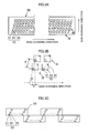
- Fig. 3A is a plan perspective diagram showing an example of the structure of a head 50
- Fig. 3B is a partial enlarged diagram of same
- Fig. 3C is a plan view perspective diagram showing a further example of the structure of the head 50
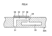
- Fig. 4 is a cross-sectional diagram showing the composition of an ink chamber unit (a cross-sectional diagram along line IV-IV in Figs. 3A and 3B ).
- the head 50 has a structure in which a plurality of ink chamber units 53, each comprising a nozzle 51 forming an ink droplet ejection hole, a pressure chamber 52 corresponding to the nozzle 51, and the like, are disposed two-dimensionally in the form of a staggered matrix, and hence the effective nozzle interval (the projected nozzle pitch) as projected in the lengthwise direction of the head (the main scanning direction perpendicular to the paper conveyance direction) is reduced and high nozzle density is achieved.
- a line head having nozzle rows of a length corresponding to the entire width of the recording paper 16 can be formed by arranging and combining, in a staggered matrix, short modules (head chips) 50' having a plurality of nozzles 51 arrayed in a two-dimensional fashion.
- short modules head chips
- the pressure chambers 52 provided corresponding to the respective nozzles 51 are approximately square-shaped in planar form, and a nozzle 51 and an ink inflow port 54 are provided respectively at either corner of a diagonal of each pressure chamber 52.
- Each pressure chamber 52 is connected via the ink inflow port 54 to a common flow channel 55.
- Piezoelectric elements 58 respectively provided with individual electrodes 57 are bonded to a diaphragm 56 which forms the upper face of the pressure chambers 52 and also serves as a common electrode, and each piezoelectric element 58 is deformed when a drive voltage is supplied to the corresponding individual electrode 57, thereby causing ink to be ejected from the corresponding nozzle 51.
- ink is ejected, new ink is supplied to the pressure chambers 52 from the common flow channel 55, via the ink inlet ports 54.
- a piezoelectric element 58 is used as an ink ejection force generating device which causes ink to be ejected from a nozzle 50 provided in a head 51, but it is also possible to employ a thermal method in which a heater is provided inside the pressure chamber 52 and ink is ejected by using the pressure of the film boiling action caused by the heating action of this heater.
- the high-density nozzle head according to the present embodiment is achieved by arranging a plurality of ink chamber units 53 having the above-described structure in a lattice fashion based on a fixed arrangement pattern, in a row direction which coincides with the main scanning direction, and a column direction which is inclined at a fixed angle of ⁇ with respect to the main scanning direction, rather than being perpendicular to the main scanning direction.
- the pitch P of the nozzles projected so as to align in the main scanning direction is d x cos ⁇ , and hence the nozzles 51 can be regarded to be equivalent to those arranged linearly at a fixed pitch P along the main scanning direction.
- Such configuration results in a nozzle structure in which the nozzle row projected in the main scanning direction has a high nozzle density of up to 2,400 nozzles per inch.
- the arrangement structure of the nozzles is not limited to the example shown in the drawings, and it is also possible to apply various other types of nozzle arrangements, such as an arrangement structure having one nozzle row in the sub-scanning direction.
- the scope of application of the present invention is not limited to a printing system based on a line type of head, and it is also possible to adopt a serial system where a short head which is shorter than the breadthways dimension of the recording paper 16 is scanned in the breadthways direction (main scanning direction) of the recording paper 16, thereby performing printing in the breadthways direction, and when one printing action in the breadthways direction has been completed, the recording paper 16 is moved through a prescribed amount in the direction perpendicular to the breadthways direction (the sub-scanning direction), printing in the breadthways direction of the recording paper 16 is carried out in the next printing region, and by repeating this sequence, printing is performed over the whole surface of the printing region of the recording paper 16.
- Fig. 5 is a principal block diagram showing the control system of the inkjet recording apparatus 10.
- the inkjet recording apparatus 10 comprises a communications interface 70, a system controller 72, a memory 74, a motor driver 76, a heater driver 78, a print control unit 80, an image buffer memory 82, a head driver 84, a liquid temperature control unit 96, a valve control unit 98, and the like.
- the communications interface 70 is an interface unit for receiving image data sent from a host computer 86.
- a serial interface such as USB (Universal Serial Bus), IEEE1394, Ethernet (registered trademark), wireless network, or a parallel interface such as a Centronics interface may be used as the communications interface 70.
- a buffer memory (not shown) may be mounted in this portion in order to increase the communication speed.
- the image data sent from the host computer 86 is received by the inkjet recording apparatus 10 through the communications interface 70, and is temporarily stored in the memory 74.
- the memory 74 is a storage device for temporarily storing images inputted through the communications interface 70, and data is written and read to and from the memory 74 through the system controller 72.
- the memory 74 is not limited to a memory composed of semiconductor elements, and a hard disk drive or another magnetic medium may be used.
- the system controller 72 is a control unit which controls the respective sections, such as the communications interface 70, the memory 74, the motor driver 76, the heater driver 78, the pump driver 92, the liquid temperature control unit 96, the valve control unit 98, and the like.
- the system controller 72 is made up of a central processing unit (CPU) and peripheral circuits thereof, and as well as controlling communications with the host computer 86 and controlling reading from and writing to the memory 74, and the like, and it generates control signals for controlling the motors 88 of the conveyance system and the heaters 89.
- CPU central processing unit
- the memory 74 may be a non-writeable storage device, or it may be a rewriteable storage device, such as an EEPROM.
- the memory 74 is used as a temporary storage region for the image data, and it is also used as a program development region and a calculation work region for the CPU.
- the program storage unit 90 may use a semiconductor memory such as ROM or an EEPROM, or may use a magnetic disk or the like. An external interface may be provided and a memory card or a PC card may be used. It goes without saying that a plurality of recording media may be selected from among these recording media.
- the program storage unit 90 may be also used together with a storage device (not shown in the figure) of an operation parameter or the like.
- the motor driver (drive circuit) 76 drives the motor 88 in accordance with commands from the system controller 72.
- the heater driver 78 drives the heater 89 of the post-drying unit 42 and the like in accordance with commands from the system controller 72.
- the pump driver 92 is a driver that drives the pump 94 according to an instruction from the system controller 72.
- the pump 94 shown in Fig. 5 includes pumps (for example, a pump 102 in Fig. 6 ) disposed in the ink supply system of the inkjet recording apparatus 10.
- the liquid temperature control unit 96 is a control unit that controls the temperature of liquid medium (cooling water) of the liquid temperature adjusting device 106 according to an instruction from the system controller 72.
- the liquid temperature adjusting device 106 is provided as a device shared by all colors, rather than for each ink color, and the liquid medium adjusted to the predetermined temperature by the liquid temperature adjusting device 106 circulates in the heat exchange units 104 (see Fig. 6 ) provided respectively for the colors.
- the valve control unit 98 controls the valve 99 according to an instruction from the system controller 72.
- the valve 99 shown in Fig. 5 includes the flow rate control valve 108 shown in Fig. 6 and the electromagnetic valve 132 shown in Fig. 10 .
- the print control unit 80 has a signal processing function for performing various tasks, compensations, and other types of processing for generating print control signals from the image data stored in the memory 74 in accordance with commands from the system controller 72 so as to supply the generated print control signals (dot data) to the head driver 84.
- Necessary signal processing is carried out in the print control unit 80, and the ejection amount and the ejection timing of the ink from the respective recording heads 50 are controlled via the head driver 84, on the basis of the print data. By this means, desired dot size and dot positions can be achieved.
- the print control unit 80 is provided with the image buffer memory 82; and image data, parameters, and other data are temporarily stored in the image buffer memory 82 when image data is processed in the print control unit 80.
- the aspect illustrated in Fig. 5 is one in which the image buffer memory 82 accompanies the print control unit 80; however, the memory 74 may also serve as the image buffer memory 82. Also possible is an aspect in which the print control unit 80 and the system controller 72 are integrated to form a single processor.
- the head driver 84 generates drive signals for driving the piezoelectric elements 58 (see Fig. 4 ) of the recording heads 50 of the respective colors, on the basis of dot data supplied from the print control unit 80, and supplies the generated drive signals to the piezoelectric elements 58.
- a feedback control system for maintaining constant drive conditions in the recording heads 50 may be included in the head driver 84.
- the print determination unit 24 is a block that includes the line sensor as described above with reference to Fig. 1 , reads the image printed on the recording paper 16, determines the print conditions (presence of the ejection, variation in the dot formation, and the like) by performing prescribed signal processing, and the like, and provides the determination results of the print conditions to the print control unit 80.
- the print control unit 80 makes various corrections with respect to the recording head 50 on the basis of information obtained from the print determination unit 24.
- Fig. 6 is a schematic drawing illustrating a configuration example of ink supply system according to a first embodiment.
- the ink supply system according to the first embodiment is constituted mainly by a head 50, a liquid storage unit 100, a pump 102, and a heat exchange unit 104 for each ink color.
- the ink storage unit 100 is a basic tank (ink supply source) accommodating ink for supply to each corresponding head 50 and corresponds to a tank disposed in the ink storage/loading unit 14 shown in Fig, 1 .
- the pump 102 is a pumping device installed between the liquid storage unit 100 and the head 50. By driving the pump 102, the ink is supplied from the liquid storage unit 100 to the head 50.
- the pump 102 is installed between the heat exchange unit 104 and the head 50, but this configuration is not limiting, and the pump 102 may be also installed between the liquid storage unit 100 and the heat exchange unit 104.
- the heat exchange unit 104 is a heat exchange device installed between the liquid storage unit 100 and the head 50.
- the liquid medium (cooling water) supplied from the below-described liquid temperature adjusting device 106 is circulated in the heat exchange unit 104, and when the ink is supplied from the liquid storage unit 100 to the head 50, the temperature of ink passing through the heat exchange unit 104 is adjusted by heat exchange with the liquid medium.
- the liquid temperature adjusting device (chiller) 106 is a device that causes the liquid medium (cooling water) adjusted to the predetermined temperature to circulate between the liquid temperature adjusting device 106 and each heat exchange unit 104.
- the liquid medium adjusted to the predetermined temperature in the liquid temperature adjusting device 106 is supplied to each heat exchange unit 104 via a plurality of first branch flow paths 116 which branch off from one supply flow path 114.
- the liquid medium that has circulated inside the heat exchange units 104 and has been discharged is returned from second branch flow paths 118 respectively connected to the heat exchange units 104 to the liquid temperature adjusting device 106 via a single merged recovery flow path 120.
- the liquid temperature adjusting device 106 incorporates a pump (not shown in the figures) as a pumping device for causing the liquid medium to circulate between the liquid temperature adjusting device 106 and the heat exchange units 104.
- the pump can be also provided outside the liquid temperature adjusting device 106.
- Respective flow rate control valves 108 are provided between the liquid temperature adjusting device 106 and the heat exchange units 104.
- the flow rate control valves 108 are flow rate adjusting devices that adjust the supplied amount (circulated amount) of liquid medium (cooling water) supplied from the liquid temperature adjusting device 106 to the heat exchange units 104.
- the flow rate control valves 108 are controlled by the below-described controller 112.
- Each head 50 is provided with a temperature sensor 110.
- the temperature sensor 110 is an ink temperature measuring device that measures the temperature of ink inside the head 50.
- the controller 112 is notified of the ink temperature (measured value) measured by the temperature sensor 110,
- the temperature sensor 110 may measure not only the temperature of ink inside the head 50, but also the temperature of ink flowing in a flow path connected to the head 50.
- the controller 112 changes the opening area (opening ratio) of the corresponding flow rate control valve 108 on the basis of ink temperature sent from each temperature sensor 110, so as to control the supplied amount (circulated amount) of liquid medium supplied from the liquid temperature adjusting device 106 to each heat exchange unit 104.
- the controller 112 is a controller corresponding to the system controller 72 and valve control unit 98 shown in Fig. 5 .
- Fig. 7 shows how the ink outlet temperature (outlet temperature of ink flowing out from the heat exchange unit 104) varies when the cooling water flow rate is changed in the case in which cooling water is used as the liquid medium.
- the graph in Fig. 7 shows the relationship between the cooling water flow rate and the ink outlet temperature when the ink inlet temperature (inlet temperature of ink flowing into the heat exchange unit 104) is taken as 64°C-and the cooling water inlet temperature (temperature of cooling water supplied to the heat exchange unit 104) is taken as 18°C.
- the cooling water flow rate is increased, the heat exchange ratio in the heat exchange unit 104 rises, the ink can be better cooled by the heat exchange unit 104 and the ink outlet temperature can be lowered.
- the flow rate control valve 108 is controlled so as to increase the flow rate of liquid medium circulating in the heat exchange unit 104.
- the heat exchange ratio in the heat exchange unit 104 can be raised and the temperature of ink supplied to the head 50 (outlet temperature of ink flowing out from the heat exchange unit 104) can be lowered.
- the controller 112 controls the flow rate control valve 108 so as to reduce the flow rate of liquid medium circulating in the heat exchange unit 104.
- the heat exchange ratio in the heat exchange unit 104 can be reduced and the temperature of ink supplied to the head 50 can be raised.
- the configuration example shown in Fig. 6 relates to a feedback control system in which a difference between the temperature of ink supplied to the head 50 and the reference value (reference temperature) is reflected in the opening ratio of the flow rate control valve 108.
- the opening area (opening degree) of the flow rate control valve 108K corresponding to the head 50K is increased, the supplied amount of liquid medium supplied to the heat exchange unit 104C is raised and the heat exchange ratio (temperature adjustment efficiency) of the heat exchange unit 104C is increased.
- the increase in the opening area (opening degree) of the flow rate control valve 108 may not be as large as in the case in which the aforementioned solid image is formed.
- each flow rate control valve 108 provided between the liquid temperature adjusting device 106 and the heat exchange units 104, it is possible to change individually the supplied amount (circulated amount) of liquid medium supplied to each heat exchange unit 104 and vary the heat exchange ratio between the ink and liquid medium in each heat exchange unit 104 with respect to each heat exchange unit 104 (that is, with respect to each ink color).
- the temperature of ink supplied to the head 50 corresponding to each color can be individually adjusted, ejection of each head 50 can be stabilized, and inconveniences such as density unevenness caused by the difference in ink temperature can be eliminated.
- each head 50 can be adjusted for each ink color (each head) only by changing the supplied amount of liquid medium supplied to each heat exchange unit 104, no excess temperature adjustment capability is required for each ink color and cost can be reduced.
- the feedback control system configuration is shown in which the flow rate control valve 108 is controlled on the basis of ink temperature inside the head 50, but such a configuration is not limiting, and a configuration of feedback control system conducting control on the basis of ink amount (flow rate) supplied to the head 50 or ejection ratio of the head 50 is also beneficial.
- Fig. 8 is a schematic diagram illustrating another configuration example of ink supply system according to the first embodiment.
- components common or analogous to those shown in Fig. 6 are assigned with like numeral symbols and explanation thereof is omitted.
- the configuration shown in Fig. 8 is provided with a plurality of revolution speed sensors 122 (122K, 122C, 122M, 122Y) that determine revolution speed of the pumps 102 respectively.
- Each revolution speed sensor 122 detects the revolution speed of the corresponding pump 102, and notifies the controller 112 of the detection result.
- the controller 112 controls the corresponding flow rate control valve 108 on the basis of the detected value (revolution speed of the pump 102) received from each revolution speed sensor 122.
- the controller 112 controls the flow rate control valve 108 so that the flow rate of liquid medium circulating in the heat exchange unit 104 decreases.
- the heat exchange efficiency (heat exchange rate) in the heat exchange unit 104 decreases, the temperature of ink supplied to the head 50 rises, and the ink temperature inside the head 50 gradually approaches the reference value.
- the controller 112 controls the flow rate control valve 108 so that the flow rate of liquid medium circulating in the heat exchange unit 104 increases.
- the heat exchange efficiency (heat exchange rate) in the heat exchange unit 104 increases, the temperature of ink supplied to the head 50 is lowered, and the ink temperature inside the head 50 gradually approaches the reference value.
- the revolution speed sensors 122 detecting the revolution speed of the pumps 102 are provided as a means for detecting the amount of ink supplied to the heads 50, but this configuration is not limiting and a flow rate sensor detecting the flow rate (ink supply amount) in the ink supply paths from the liquid storage unit 100 towards the heads 50 may be also provided.
- the controller 112 controls each flow rate control valve 108 so as to increase or decrease the heat exchange efficiency of each heat exchange unit 104 on the basis of ink amount detected by each flow rate sensor.
- a table indicating the relationship between the revolution speed of the pump 102 and the opening ratio of the flow rate control valve 108 is maintained and feedforward control is performed by which the opening ratio of the flow rate control valve 108 is changed according to the revolution speed of the pump 102.
- Fig. 9 is a schematic diagram illustrating yet another configuration example of an ink supply system according to the first embodiment.
- components common or analogous to those shown in Fig. 6 are assigned with like numeral symbols and explanation thereof is omitted.
- the print control unit 80 (see Fig. 5 ) generates dot data from input image data, drives each head 50 via the head driver 84 (not shown in Fig. 9 ) shown in Fig. 5 , calculates the ejection ratio of each head 50, and sends the calculation results to the controller 112.
- the controller 112 controls each flow rate control valve 108 on the basis of the ejection ratio of each head 50 received from the print control unit 80 (see Fig. 5 ).
- the controller 112 controls the flow rate control valve 108 so that the flow rate of liquid medium circulating in the heat exchange unit 104 decreases.
- the heat exchange efficiency in the heat exchange unit 104 is low, the temperature of ink supplied to the head 50 rises, and the ink temperature inside the head 50 gradually approaches the reference value.
- the controller 112 controls the flow rate control valve 108 so that the flow rate of liquid medium circulating in the heat exchange unit 104 increases.
- the heat exchange efficiency in the heat exchange unit 104 increases, the temperature of ink supplied to the head 50 decreases, and the ink temperature inside the head 50 gradually approaches the reference value.
- a table indicating the relationship between the ejection ratio of the head 50 and the opening ratio of the flow rate control valve 108 is maintained and feedforward control is performed by which the opening ratio of the flow rate control valve 108 is changed according to the ejection ratio of the head 50.
- a non-circulation system is described in which the ink does not circulate between the liquid storage unit 100 and the head 50, but this configuration is not limiting and the present invention can be similarly applied to a circulation system in which the ink circulates between the liquid storage unit 100 and the head 50.
- Fig. 10 is a schematic diagram illustrating a configuration example of an ink supply system according to a second embodiment.
- components common or analogous to those shown in Fig. 6 are assigned with like numeral symbols and explanation thereof is omitted.
- components outside the configuration between the liquid temperature adjusting device 106 and the heat exchange units 104 that is, the configuration between the liquid storage unit 100 and the heads 50
- these components are not shown in Fig. 10 .
- the ink supply system according to the second embodiment is similar to that of the first embodiment in that the liquid temperature adjusting device 106 and the heat exchange unit 104 are linked by a supply flow path 114 and each of a plurality of first branched flow paths 116 which branch off from the supply flow path 114 is provided with a flow rate adjusting device, but the configuration of the flow rate adjusting device in the second embodiment is different from that in the first embodiment.
- the flow rate control valves 108 see Fig. 6
- electromagnetic valves 132 are used.
- a plurality of flow paths (referred to hereinbelow as parallel flow paths) 130A, 130B, 130C are connected in parallel to each of the first branched flow paths 116, and the electromagnetic valve 132 is provided in each of the parallel flow paths 130A, 130B, 130C.
- Part (some) or all of the parallel flow paths 130A, 130B, 130C may have different flow path resistances, or all of the flow paths may have the same resistance.
- the adjustment range of the supplied amount of liquid medium supplied to each heat exchange unit 104 can be expanded.
- flow rate control of the liquid medium in the heat exchange units 104 can be simplified because the supplied amount of liquid medium supplied to the heat exchange unit 104 is proportional to the number of parallel flow paths in which the electromagnetic valve 132 is open, from among the parallel flow paths 130A, 130B, 130C corresponding to this heat exchange unit 104.
- the ratio of flow path resistances of the parallel flow paths 130A, 130B, 130C is 1 : 2 : 4, and the ratio of flow rates of liquid medium flowing in the parallel flow paths 130A, 130B, 130C is 4 : 2 : 1.
- Opening and closing of the electromagnetic valves 132 provided in the parallel flow paths 130A, 130B, 130C respectively is controlled by the controller 112.
- This control by the controller 112 is performed in the same manner as in the first embodiment and explanation thereof is herein omitted to avoid redundancy.
- the second embodiment by connecting in parallel a plurality of parallel flow paths 130A to 130C to the first branched flow paths 116 connected to respective heat exchange units 104 and controlling together the opening and closing of electromagnetic valves 132 installed in each of the parallel flow paths 130A to 130C, it is possible to change individually the supply amounts of liquid medium supplied to the heat exchange units 104 and vary the heat exchange ratio of ink and liquid medium in the heat exchange units 104 with respect to each heat exchange unit 104 (that is, with respect to each ink color). As a result, the temperature of ink supplied to the head 50 corresponding to each color can be individually adjusted and inconveniences such as density unevenness caused by the difference in ink temperature can be eliminated.
- electromagnetic valves 132 that are less expensive and easier to control than the flow rate control valve 108 (see Fig. 6 ) are used as the flow rate adjusting means, the cost of the ink supply system (ink supply device) of the inkjet recording apparatus 10 can be reduced.
- the liquid medium is supplied from one liquid temperature adjusting device 106 to a plurality of heat exchange units 104. Therefore, when the supplied amount (circulating amount) of liquid medium to one heat exchange unit 104 is changed by controlling the flow rate control valve 108 or the electromagnetic valve 132, the supplied amount (circulating amount) of liquid medium to another heat exchange unit 104 also changes. As a result, the outlet temperature of ink flowing out of the other heat exchange unit 104 can be assumed to be changed.
- Ink Outlet Temperature ⁇ ⁇ Liquid Medium Temperature + 1 ⁇ ⁇ ⁇ Ink Inlet Temperature
- ⁇ a physical parameter of the heat exchange unit 104
- W a liquid medium flow rate (supplied amount of the liquid medium supplied to the heat exchange unit 104).
- the controller 112 when the controller 112 changes the supplied amount (circulating amount) of liquid medium to one heat exchange unit 104 by controlling the flow rate control valves 108 or the electromagnetic valves 132, the temperature of liquid medium of the liquid temperature adjusting device 106 is controlled simultaneously. With such control, it is possible to maintain a constant ink outlet temperature of another heat exchange unit 104.
- the liquid medium temperature is determined from Formula (2).
Landscapes
- Ink Jet (AREA)
Abstract
Description
- The present invention relates to a liquid supply apparatus and an image forming apparatus, and more particularly to a technique for performing temperature control of a liquid supplied to a liquid ejection head.
- An inkjet recording apparatus is provided with a recording head (inkjet head) in which a plurality of nozzles are arranged in an ejection plane, and an image is formed on a recording medium by ejecting ink droplets from the nozzles, while the recording medium and the recording head are moved relative to each other. Examples of an ink ejection system of the recording head include a piezoelectric system in which the displacement of a piezoelectric element is used to pressurize the ink inside a pressure chamber and eject an ink droplet from the nozzle, and a thermal system in which thermal energy generated by a heat-generating element such as a heater is used to generate a gas bubble inside a pressure chamber and eject an ink droplet from the nozzle by the generated pressure.
- Such inkjet recording apparatuses can be of a serial system or a line system. The serial system is provided with a recording head in which nozzle rows are disposed along the conveyance direction of the recording medium and recording is performed by repeating intermittently the reciprocating movement of the recording head in the widthwise direction of the recording medium (direction perpendicular to the paper conveyance direction; main scanning direction) and conveyance of the recording medium. The line system is provided with a receding head in which nozzle rows are disposed along the widthwise direction of the recording medium and recording is performed by moving the recording medium in the paper conveyance direction (sub-scanning direction) with respect to the recording head. One of the benefits of the line system over the serial system is in that the recording speed can be increased, and the line system can be applied widely to various industrial fields.
- An ink supply system (ink supply device) of the inkjet recording apparatus is provided with an ink tank accommodating ink to be supplied to the recording head. The ink tank and the recording head are linked by an ink supply path, and a pump serving as a liquid pumping device is installed in the ink supply path. The ink is supplied from the ink tank into the recording head via the ink supply path by driving the pump.
- The viscosity of ink used in the inkjet recording apparatus changes according to temperature. Therefore, when the temperature of ink supplied to the recording head changes, the ink viscosity changes, thereby causing variations in ink ejection characteristics. For example, when the ink temperature decreases, the ink viscosity increases, causing reduction in the ejection amount or decrease in the flying velocity of the ink and creating density unevenness in the recorded image. Accordingly, inkjet recording apparatuses have been heretofore suggested that are provided with a temperature adjusting mechanism for adjusting the temperature of ink supplied to the recording head, with the object of stabilizing the ejection characteristic of the recording head (see, for example, Japanese Patent Application Publication No.
3-104655 - However, since the inkjet recording apparatus described in Japanese Patent Application Publication No.
3-104655 - In particular, in an inkjet recording apparatus of a line system, increase in the recording speed and increase in quality of recorded images are required together with wide printing. Therefore, the amount of ink consumed by the recording head (ejection amount) is increased and the amount of generated heat also increases due to increase in a drive frequency. Further, since accuracy needed for ink temperature rises, a controllable temperature range of ink is narrowed.
- Thus, a strong temperature adjustment capability is needed for the ink supplied to the recording head and a stringent requirement is also placed on control accuracy relating to ink temperature adjustment. The problem is that these requirements cannot be met by the temperature adjustment performed by air cooling, such as used in the inkjet recording apparatus described in Japanese Patent Application Publication No.
3-104655 - Using a water cooling system to adjust the temperature of ink supplied to the recording head can be also considered, but this approach could result in undesirable significant cost increase because the ink temperature is adjusted separately for each recording head.
- The present invention has been conceived with the foregoing in view and it is an object of the present invention to provide a liquid supply apparatus and an image forming apparatus that can adjust the temperature of liquid supplied to a liquid ejection head and stabilize the ejection of the liquid ejection head, without increasing the cost significantly.
- In order to attain an object described above, one aspect of the present invention is directed to a liquid supply apparatus comprising: a plurality of heat exchange devices which are respectively provided in a plurality of supply paths for supplying liquids to a plurality of liquid ejection heads respectively, are supplied with a liquid medium adjusted to a predetermined temperature from a liquid temperature adjusting device, and conduct heat exchange between the liquids flowing in the plurality of supply paths and the liquid medium supplied from the liquid temperature adjusting device; a plurality of flow rate adjusting devices which are respectively provided correspondingly to the plurality of heat exchange devices and adjust a flow rate of the liquid medium supplied to each of the plurality of heat exchange devices from the liquid temperature adjusting device; and a controller which controls each of the plurality of flow rate adjusting devices to individually change the flow rate of the liquid medium supplied from the liquid temperature adjusting device to the plurality of heat exchange devices.
- According to this aspect of the invention, by controlling each of the flow rate control valves provided respectively between the liquid temperature adjusting device and the heat exchange units, the supplied amount of liquid medium that is supplied to each heat exchange unit can be individually changed and the heat exchange ratio of liquid (ink) and liquid medium in each heat exchange unit can be varied for each heat exchange unit. As a result, the temperature of liquid supplied to each liquid ejection head can be individually adjusted, ejection stability of each liquid ejection head can be stabilized, and inconveniences such as density unevenness caused by the difference in liquid temperature can be eliminated. Further, since the temperature of liquid supplied to each liquid ejection head can be adjusted for each type of liquid (for example, for each color of liquid) only by changing the supplied amount of liquid medium supplied to each heat exchange unit, no excess temperature adjustment capability is required for each type of liquid and cost can be reduced.
- Desirably, the plurality of flow rate adjusting devices are flow rate control valves; and the controller changes opening area of the flow rate control valves to change the flow rate of the liquid medium supplied from the liquid temperature adjusting device to the plurality of heat exchange devices.
- According to this aspect of the invention, the flow rate of liquid medium supplied to each heat exchange unit can be finely adjusted for each heat exchange unit and the temperature of liquid supplied to each liquid ejection head can be optimized.
- Desirably, each of the plurality of flow rate adjusting devices includes a plurality of parallel flow paths in parallel connected in an individual flow path of the liquid medium to the heat exchange device, and a plurality of electromagnetic valves respectively provided in the plurality of parallel flow paths; and the controller controls opening and closing of the plurality of electromagnetic valves to change the flow rate of the liquid medium supplied from the liquid temperature adjusting device to the plurality of heat exchange devices.
- According to this aspect of the invention, the flow rate of liquid supplied to each heat exchange unit can be adjusted by controlling together the opening and closing of electromagnetic valves provided in each parallel flow path. Further, by using electromagnetic valves that are cheaper and easier to control than flow rate control valves, it is possible to reduce the cost of the liquid supply apparatus.
- Desirably, part or all of the plurality of parallel flow paths have mutually different flow path resistances.
- According to this aspect of the invention, the adjustment range of the flow rate of liquid supplied to each heat exchange unit can be broadened.
- Desirably, all of the plurality of parallel flow paths have a same flow path resistance.
- According to this aspect of the invention, since the flow rate of liquid supplied to a heat exchange units is proportional to the number of parallel flow paths in which electromagnetic valves are open, from among the plurality of parallel flow paths corresponding to the heat exchange unit, the flow rate control performed by the controller can be simplified.
- Desirably, the liquid supply apparatus further comprises a plurality of liquid temperature measuring devices which measure temperature of the liquids supplied to the plurality of liquid ejection heads respectively, wherein the controller controls each of the plurality of flow rate adjusting devices according to the temperature of the liquids measured by the plurality of liquid temperature measuring devices.
- According to this aspect of the invention, by adjusting the flow rate of liquid medium supplied to the heat exchange units correspondingly to the temperature of liquid inside the liquid ejection heads, it is possible to set the liquid inside the liquid ejection heads to desired temperature.
- Desirably, the liquid supply apparatus further comprises a plurality of liquid flow rate measuring devices which measure flow rates of the liquids supplied to the plurality of liquid ejection heads respectively, wherein the controller controls each of the plurality of flow rate adjusting devices according to the flow rates of the liquids measured by the plurality of liquid flow rate measuring devices.
- In this aspect of the invention, the liquid flow rate measuring devices may be flow rate sensors provided in supply paths for supplying the liquid to the liquid ejection heads, or may be revolution speed sensors that detect the revolution speed of pumps provided as liquid pumping devices in the supply paths.
- Desirably, the liquid supply apparatus further comprises a head ejection ratio calculation device which calculates ejection ratios of the plurality of liquid ejection heads,
wherein the controller controls the plurality of flow rate adjusting devices according to the ejection ratios of the plurality of liquid ejection heads calculated by the head ejection ratio calculation device. - In this aspect of the invention, the flow rate of liquid medium supplied to the heat exchange units is desirably adjusted according to the ejection ratios of the liquid ejection heads. There is a correlation between the ejection ratio of the liquid ejection head and the temperature of liquid inside thereof, and by adjusting the flow rate of liquid medium supplied to the heat exchange units on the basis of the ejection ratios of the liquid ejection heads, it is possible to set the liquid inside the liquid ejection heads to desired temperature.
- Desirably, the controller controls each of the plurality of flow rate adjusting devices and also controls temperature of the liquid medium adjusted by the liquid temperature adjusting device.
- According to this aspect of the invention, the temperature of liquid supplied to each liquid ejection head can be further optimized.
- In order to attain an object described above, another aspect of the present invention is directed to an image forming apparatus comprising any one of the liquid supply apparatuses above.
- According to the present invention, by controlling each of the flow rate control valves provided between the liquid temperature adjusting device and heat exchange units, the supplied amount of liquid medium that is supplied to each heat exchange unit can be individually changed and the heat exchange ratio of ink and liquid medium in each heat exchange unit can be varied for each heat exchange unit. As a result, the temperature of liquid supplied to each liquid ejection head can be individually adjusted, ejection stability of each liquid ejection head can be stabilized, and inconveniences such as density unevenness caused by the difference in liquid temperature can be eliminated. Further, since the temperature of liquid supplied to each liquid ejection head can be adjusted for each type of liquid (for example, for each color of liquid) by changing the supplied amount of liquid medium supplied to each heat exchange unit, no excess temperature adjustment capability is required for each type of liquid and cost can be reduced.
- The nature of this invention, as well as other objects and benefits thereof, will be explained in the following with reference to the accompanying drawings, in which like reference characters designate the same or similar parts throughout the figures and wherein:
-
Fig. 1 is a general configuration drawing illustrating schematically an inkjet recording apparatus; -
Fig. 2 is a principal plan view illustrating a printing unit periphery of the inkjet recording apparatus; -
Figs. 3A to 3C are plan transparent views illustrating examples of head structure; -
Fig. 4 is a cross-sectional view illustrating an ink chamber unit; -
Fig. 5 is a principal block diagram illustrating a control system of the inkjet recording apparatus; -
Fig. 6 is a schematic drawing illustrating a configuration example of an ink supply system according to a first embodiment; -
Fig. 7 is a graph showing an example of relationship between the cooling water flow rate and warm water outlet temperature; -
Fig. 8 is a schematic diagram illustrating another configuration example of an ink supply system according to the first embodiment; -
Fig. 9 is a schematic diagram illustrating yet another configuration example of the ink supply system according to the first embodiment, and -
Fig. 10 is a schematic diagram illustrating a configuration example of an ink supply system according to a second embodiment. -
Fig. 1 is a general schematic configuration diagram of an inkjet recording apparatus according to an embodiment of an image forming apparatus of the present invention. As illustrated inFig. 1 , theinkjet recording apparatus 10 comprises: aprinting unit 12 having a plurality of recording heads (hereafter, also simply called "heads") 50K, 50C, 50M, and 50Y provided for the respective ink colors; an ink storing andloading unit 14 for storing inks of K, C, M and Y to be supplied to the printing heads 50K, 50C, 50M, and 50Y; apaper supply unit 18 for supplyingrecording paper 16; adecurling unit 20 removing curl in therecording paper 16; a suctionbelt conveyance unit 22 disposed facing the nozzle face (ink-droplet ejection face) of theprinting unit 12, for conveying therecording paper 16 while keeping therecording paper 16 flat; aprint determination unit 24 for reading the printed result produced by theprinting unit 12; and apaper output unit 26 for outputting image-printed paper (printed matter) to the exterior. - In
Fig. 1 , a magazine for rolled paper (continuous paper) is shown as an example of thepaper supply unit 18; however, more magazines with paper differences such as paper width and quality may be jointly provided. Moreover, papers may be supplied with cassettes that contain cut papers loaded in layers and that are used jointly or in lieu of the magazine for rolled paper. - In the case of the configuration in which roll paper is used, a
cutter 28 is provided as illustrated inFig. 1 , and the continuous paper is cut into a desired size by thecutter 28. Thecutter 28 has astationary blade 28A, whose length is not less than the width of the conveyor pathway of therecording paper 16, and around blade 28B, which moves along thestationary blade 28A. Thestationary blade 28A is disposed on the reverse side of the printed surface of therecording paper 16, and theround blade 28B is disposed on the printed surface side across the conveyor pathway. When cut papers are used, thecutter 28 is not required. - In the case of a configuration in which a plurality of types of recording paper can be used, it is desirable that an information recording medium such as a bar code and a wireless tag containing information about the type of paper is attached to the magazine, and by reading the information contained in the information recording medium with a predetermined reading device, the type of paper to be used is automatically determined, and ink-droplet ejection is controlled so that the ink-droplets are ejected in an appropriate manner in accordance with the type of paper.
- The
recording paper 16 delivered from thepaper supply unit 18 retains curl due to having been loaded in the magazine. In order to remove the curl, heat is applied to therecording paper 16 in thedecurling unit 20 by aheating drum 30 in the direction opposite from the curl direction in the magazine. The heating temperature at this time is desirably controlled so that therecording paper 16 has a curl in which the surface on which the print is to be made is slightly round outward. - The decurled and cut
recording paper 16 is delivered to the suctionbelt conveyance unit 22. The suctionbelt conveyance unit 22 has a configuration in which anendless belt 33 is set aroundrollers endless belt 33 facing at least the nozzle face of theprinting unit 12 and the sensor face of theprint determination unit 24 forms a plane. - The
belt 33 has a width that is greater than the width of therecording paper 16, and a plurality of suction apertures (not shown) are formed on the belt surface. Asuction chamber 34 is disposed in a position facing the sensor surface of theprint determination unit 24 and the nozzle surface of theprinting unit 12 on the interior side of thebelt 33, which is set around therollers Fig. 1 . Thesuction chamber 34 provides suction with afan 35 to generate a negative pressure, and therecording paper 16 on thebelt 33 is held by suction. - The
belt 33 is driven in the clockwise direction inFig. 1 by the motive force of a motor (not shown) being transmitted to at least one of therollers belt 33 is set around, and therecording paper 16 held on thebelt 33 is conveyed from left to right inFig. 1 . - Since ink adheres to the
belt 33 when a marginless print job or the like is performed, a belt-cleaningunit 36 is disposed in a predetermined position (a suitable position outside the printing area) on the exterior side of thebelt 33. Although the details of the configuration of the belt-cleaningunit 36 are not shown, examples thereof include a configuration in which thebelt 33 is nipped with cleaning rollers such as a brush roller and a water absorbent roller, an air blow configuration in which clean air is blown onto thebelt 33, and a combination of these. In the case of the configuration in which thebelt 33 is nipped with the cleaning rollers, it is desirable to make the line velocity of the cleaning rollers different from that of thebelt 33 to improve the cleaning effect. - A roller nip conveyance mechanism, in place of the suction
belt conveyance unit 22, can be employed. However, there is a drawback in the roller nip conveyance mechanism that the print tends to be smeared when the printing area is conveyed by the roller nip action because the nip roller makes contact with the printed surface of the paper immediately after printing. Therefore, the suction belt conveyance in which nothing comes into contact with the image surface in the printing area is desirable. - A
heating fan 40 is disposed on the upstream side of theprinting unit 12 in the conveyance pathway formed by the suctionbelt conveyance unit 22. Theheating fan 40 blows heated air onto therecording paper 16 to heat therecording paper 16 immediately before printing so that the ink deposited on therecording paper 16 dries more easily. - The
printing unit 12 is a so-called "full line head" in which a line head having a length corresponding to the maximum paper width is arranged in a direction (main scanning direction) that is perpendicular to the paper conveyance direction (sub scanning direction). Each of the printing heads 50K, 50C, 50M, and 50Y constituting theprinting unit 12 is constituted by a line head, in which a plurality of ink ejection ports (nozzles) are arranged along a length that exceeds at least one side of the maximum-size recording paper 16 intended for use in the inkjet recording apparatus 10 (seeFig. 2 ). - The printing heads 50K, 50C, 50M, and 50Y are arranged in the order of black (K), cyan (C), magenta (M), and yellow (Y) from the upstream side, along the feed direction of the recording paper 16 (hereinafter, referred to as the sub-scanning direction). A color image can be formed on the
recording paper 16 by ejecting the inks from the printing heads 50K, 50C, 50M, and 50Y, respectively, onto therecording paper 16 while conveying therecording paper 16. - By adopting the
printing unit 12 in which the full line heads covering the full paper width are provided for the respective ink colors in this way, it is possible to record an image on the full surface of therecording paper 16 by performing just one operation of relatively moving therecording paper 16 and theprinting unit 12 in the paper conveyance direction (the sub-scanning direction), in other words, by means of a single sub-scanning action. Higher-speed printing is thereby made possible and productivity can be improved in comparison with a shuttle type head configuration in which a head reciprocates in a direction (the main scanning direction) orthogonal to the paper conveyance direction. - Although the configuration with the KCMY four standard colors is described in the present embodiment, combinations of the ink colors and the number of colors are not limited to those. Light inks or dark inks can be added as required. For example, a configuration is possible in which heads for ejecting light-colored inks such as light cyan and light magenta are added. Furthermore, there are no particular restrictions of the sequence in which the heads of respective colors are arranged.
- As illustrated in
Fig. 1 , the ink storing andloading unit 14 has tanks for storing the inks of K, C, M and Y to be supplied to theheads heads loading unit 14 has a warning device (for example, a display device or an alarm sound generator) for warning when the remaining amount of any ink is low, and has a mechanism for preventing loading errors among the colors. - The
print determination unit 24 has an image sensor (line sensor) for capturing an image of the ink-droplet deposition result of theprinting unit 12, and functions as a device to check for ejection defects such as clogs of the nozzles in theprinting unit 12 from the ink-droplet deposition results evaluated by the image sensor. - The
print determination unit 24 of the present embodiment is configured with at least a line sensor having rows of photoelectric transducing elements with a width that is greater than the ink-droplet ejection width (image recording width) of theheads - The
print determination unit 24 reads a test pattern image printed by theheads - A
post-drying unit 42 is disposed following theprint determination unit 24. Thepost-drying unit 42 is a device to dry the printed image surface, and includes a heating fan, for example. It is desirable to avoid contact with the printed surface until the printed ink dries, and a device that blows heated air onto the printed surface is desirable. - In cases in which printing is performed with dye-based ink on porous paper, blocking the pores of the paper by the application of pressure prevents the ink from coming contact with ozone and other substances that cause dye molecules to break down, and has the effect of increasing the durability of the print.
- A heating/
pressurizing unit 44 is disposed following thepost-drying unit 42. The heating/pressurizing unit 44 is a device to control the glossiness of the image surface, and the image surface is pressed with apressure roller 45 having a predetermined uneven surface shape while the image surface is heated, and the uneven shape is transferred to the image surface. - The printed matter generated in this manner is outputted from the
paper output unit 26. The target print (i.e., the result of printing the target image) and the test print are desirably outputted separately. In theinkjet recording apparatus 10, a sorting device (not shown) is provided for switching the outputting pathways in order to sort the printed matter with the target print and the printed matter with the test print, and to send them topaper output units 26A and 26B, respectively. When the target print and the test print are simultaneously formed in parallel on the same large sheet of paper, the test print portion is cut and separated by a cutter (second cutter) 48. Thecutter 48 is disposed directly in front of thepaper output unit 26, and is used for cutting the test print portion from the target print portion when a test print has been performed in the blank portion of the target print. The structure of thecutter 48 is the same as thefirst cutter 28 described above, and has astationary blade 48A and around blade 48B. - Although not illustrated in
Fig. 1 , the paper output unit 26A for the target prints is provided with a sorter for collecting prints according to print orders. - Next, the structure of
heads heads reference numeral 50 is hereinafter designated to any of the heads. -
Fig. 3A is a plan perspective diagram showing an example of the structure of ahead 50, andFig. 3B is a partial enlarged diagram of same. Moreover,Fig. 3C is a plan view perspective diagram showing a further example of the structure of thehead 50.Fig. 4 is a cross-sectional diagram showing the composition of an ink chamber unit (a cross-sectional diagram along line IV-IV inFigs. 3A and 3B ). - The nozzle pitch in the
head 50 should be minimized in order to maximize the density of the dots formed on the surface of the recording paper. As illustrated inFigs. 3A and 3B , thehead 50 according to the present embodiment has a structure in which a plurality ofink chamber units 53, each comprising anozzle 51 forming an ink droplet ejection hole, apressure chamber 52 corresponding to thenozzle 51, and the like, are disposed two-dimensionally in the form of a staggered matrix, and hence the effective nozzle interval (the projected nozzle pitch) as projected in the lengthwise direction of the head (the main scanning direction perpendicular to the paper conveyance direction) is reduced and high nozzle density is achieved. - The mode of forming one or more nozzle rows through a length corresponding to the entire width of the
recording paper 16 in a direction substantially perpendicular to the paper conveyance direction is not limited to the example described above. For example, instead of the configuration inFig. 3A , as illustrated inFig. 3C , a line head having nozzle rows of a length corresponding to the entire width of therecording paper 16 can be formed by arranging and combining, in a staggered matrix, short modules (head chips) 50' having a plurality ofnozzles 51 arrayed in a two-dimensional fashion. Furthermore, although not shown in the drawings, it is also possible to compose a line head by arranging short heads in one row. - The
pressure chambers 52 provided corresponding to therespective nozzles 51 are approximately square-shaped in planar form, and anozzle 51 and anink inflow port 54 are provided respectively at either corner of a diagonal of eachpressure chamber 52. Eachpressure chamber 52 is connected via theink inflow port 54 to acommon flow channel 55. -
Piezoelectric elements 58 respectively provided withindividual electrodes 57 are bonded to adiaphragm 56 which forms the upper face of thepressure chambers 52 and also serves as a common electrode, and eachpiezoelectric element 58 is deformed when a drive voltage is supplied to the correspondingindividual electrode 57, thereby causing ink to be ejected from the correspondingnozzle 51. When ink is ejected, new ink is supplied to thepressure chambers 52 from thecommon flow channel 55, via theink inlet ports 54. - In the present example, a
piezoelectric element 58 is used as an ink ejection force generating device which causes ink to be ejected from anozzle 50 provided in ahead 51, but it is also possible to employ a thermal method in which a heater is provided inside thepressure chamber 52 and ink is ejected by using the pressure of the film boiling action caused by the heating action of this heater. - As illustrated in
Fig. 3B , the high-density nozzle head according to the present embodiment is achieved by arranging a plurality ofink chamber units 53 having the above-described structure in a lattice fashion based on a fixed arrangement pattern, in a row direction which coincides with the main scanning direction, and a column direction which is inclined at a fixed angle of θ with respect to the main scanning direction, rather than being perpendicular to the main scanning direction. - More specifically, by adopting a structure in which a plurality of
ink chamber units 53 are arranged at a uniform pitch d in line with a direction forming an angle of θ with respect to the main scanning direction, the pitch P of the nozzles projected so as to align in the main scanning direction is d x cos θ, and hence thenozzles 51 can be regarded to be equivalent to those arranged linearly at a fixed pitch P along the main scanning direction. Such configuration results in a nozzle structure in which the nozzle row projected in the main scanning direction has a high nozzle density of up to 2,400 nozzles per inch. - When implementing the present invention, the arrangement structure of the nozzles is not limited to the example shown in the drawings, and it is also possible to apply various other types of nozzle arrangements, such as an arrangement structure having one nozzle row in the sub-scanning direction.
- Furthermore, the scope of application of the present invention is not limited to a printing system based on a line type of head, and it is also possible to adopt a serial system where a short head which is shorter than the breadthways dimension of the
recording paper 16 is scanned in the breadthways direction (main scanning direction) of therecording paper 16, thereby performing printing in the breadthways direction, and when one printing action in the breadthways direction has been completed, therecording paper 16 is moved through a prescribed amount in the direction perpendicular to the breadthways direction (the sub-scanning direction), printing in the breadthways direction of therecording paper 16 is carried out in the next printing region, and by repeating this sequence, printing is performed over the whole surface of the printing region of therecording paper 16. -
Fig. 5 is a principal block diagram showing the control system of theinkjet recording apparatus 10. Theinkjet recording apparatus 10 comprises acommunications interface 70, asystem controller 72, amemory 74, amotor driver 76, aheater driver 78, aprint control unit 80, animage buffer memory 82, ahead driver 84, a liquidtemperature control unit 96, avalve control unit 98, and the like. - The
communications interface 70 is an interface unit for receiving image data sent from ahost computer 86. A serial interface such as USB (Universal Serial Bus), IEEE1394, Ethernet (registered trademark), wireless network, or a parallel interface such as a Centronics interface may be used as thecommunications interface 70. A buffer memory (not shown) may be mounted in this portion in order to increase the communication speed. - The image data sent from the
host computer 86 is received by theinkjet recording apparatus 10 through thecommunications interface 70, and is temporarily stored in thememory 74. Thememory 74 is a storage device for temporarily storing images inputted through thecommunications interface 70, and data is written and read to and from thememory 74 through thesystem controller 72. Thememory 74 is not limited to a memory composed of semiconductor elements, and a hard disk drive or another magnetic medium may be used. - The
system controller 72 is a control unit which controls the respective sections, such as thecommunications interface 70, thememory 74, themotor driver 76, theheater driver 78, thepump driver 92, the liquidtemperature control unit 96, thevalve control unit 98, and the like. Thesystem controller 72 is made up of a central processing unit (CPU) and peripheral circuits thereof, and as well as controlling communications with thehost computer 86 and controlling reading from and writing to thememory 74, and the like, and it generates control signals for controlling themotors 88 of the conveyance system and theheaters 89. - Programs executed by the CPU of the
system controller 72 and the various types of data which are required for control procedures are stored in thememory 74. Thememory 74 may be a non-writeable storage device, or it may be a rewriteable storage device, such as an EEPROM. Thememory 74 is used as a temporary storage region for the image data, and it is also used as a program development region and a calculation work region for the CPU. - Various control programs are stored in the
program storage unit 90, and the control programs are read and executed in response to indications of thesystem controller 72. Theprogram storage unit 90 may use a semiconductor memory such as ROM or an EEPROM, or may use a magnetic disk or the like. An external interface may be provided and a memory card or a PC card may be used. It goes without saying that a plurality of recording media may be selected from among these recording media. Theprogram storage unit 90 may be also used together with a storage device (not shown in the figure) of an operation parameter or the like. - The motor driver (drive circuit) 76 drives the
motor 88 in accordance with commands from thesystem controller 72. Theheater driver 78 drives theheater 89 of thepost-drying unit 42 and the like in accordance with commands from thesystem controller 72. - The
pump driver 92 is a driver that drives thepump 94 according to an instruction from thesystem controller 72. Thepump 94 shown inFig. 5 includes pumps (for example, apump 102 inFig. 6 ) disposed in the ink supply system of theinkjet recording apparatus 10. - The liquid
temperature control unit 96 is a control unit that controls the temperature of liquid medium (cooling water) of the liquidtemperature adjusting device 106 according to an instruction from thesystem controller 72. As will be described below, the liquidtemperature adjusting device 106 is provided as a device shared by all colors, rather than for each ink color, and the liquid medium adjusted to the predetermined temperature by the liquidtemperature adjusting device 106 circulates in the heat exchange units 104 (seeFig. 6 ) provided respectively for the colors. - The
valve control unit 98 controls thevalve 99 according to an instruction from thesystem controller 72. Thevalve 99 shown inFig. 5 includes the flowrate control valve 108 shown inFig. 6 and theelectromagnetic valve 132 shown inFig. 10 . - The
print control unit 80 has a signal processing function for performing various tasks, compensations, and other types of processing for generating print control signals from the image data stored in thememory 74 in accordance with commands from thesystem controller 72 so as to supply the generated print control signals (dot data) to thehead driver 84. Necessary signal processing is carried out in theprint control unit 80, and the ejection amount and the ejection timing of the ink from the respective recording heads 50 are controlled via thehead driver 84, on the basis of the print data. By this means, desired dot size and dot positions can be achieved. - The
print control unit 80 is provided with theimage buffer memory 82; and image data, parameters, and other data are temporarily stored in theimage buffer memory 82 when image data is processed in theprint control unit 80. The aspect illustrated inFig. 5 is one in which theimage buffer memory 82 accompanies theprint control unit 80; however, thememory 74 may also serve as theimage buffer memory 82. Also possible is an aspect in which theprint control unit 80 and thesystem controller 72 are integrated to form a single processor. - The
head driver 84 generates drive signals for driving the piezoelectric elements 58 (seeFig. 4 ) of the recording heads 50 of the respective colors, on the basis of dot data supplied from theprint control unit 80, and supplies the generated drive signals to thepiezoelectric elements 58. A feedback control system for maintaining constant drive conditions in the recording heads 50 may be included in thehead driver 84. - The
print determination unit 24 is a block that includes the line sensor as described above with reference toFig. 1 , reads the image printed on therecording paper 16, determines the print conditions (presence of the ejection, variation in the dot formation, and the like) by performing prescribed signal processing, and the like, and provides the determination results of the print conditions to theprint control unit 80. - According to requirements, the
print control unit 80 makes various corrections with respect to therecording head 50 on the basis of information obtained from theprint determination unit 24. - Configuration examples (first and second embodiments) of ink supply system (ink supply device) of the
inkjet recording apparatus 10, which is a specific component in accordance with the present invention, will be explained below. The reference numerals of components provided for each color will be assigned at the right end thereof with an alphabet letter (C/M/Y/K) indicating each color, but when the explanation is given without distinguishing the colors, the alphabet letter and the right end of reference numeral will be omitted. -
Fig. 6 is a schematic drawing illustrating a configuration example of ink supply system according to a first embodiment. As shown inFig. 6 , the ink supply system according to the first embodiment is constituted mainly by ahead 50, aliquid storage unit 100, apump 102, and aheat exchange unit 104 for each ink color. - The
ink storage unit 100 is a basic tank (ink supply source) accommodating ink for supply to each correspondinghead 50 and corresponds to a tank disposed in the ink storage/loading unit 14 shown inFig, 1 . - The
pump 102 is a pumping device installed between theliquid storage unit 100 and thehead 50. By driving thepump 102, the ink is supplied from theliquid storage unit 100 to thehead 50. In the configuration shown by way of the example inFig, 6 , thepump 102 is installed between theheat exchange unit 104 and thehead 50, but this configuration is not limiting, and thepump 102 may be also installed between theliquid storage unit 100 and theheat exchange unit 104. - The
heat exchange unit 104 is a heat exchange device installed between theliquid storage unit 100 and thehead 50. The liquid medium (cooling water) supplied from the below-described liquidtemperature adjusting device 106 is circulated in theheat exchange unit 104, and when the ink is supplied from theliquid storage unit 100 to thehead 50, the temperature of ink passing through theheat exchange unit 104 is adjusted by heat exchange with the liquid medium. - The liquid temperature adjusting device (chiller) 106 is a device that causes the liquid medium (cooling water) adjusted to the predetermined temperature to circulate between the liquid
temperature adjusting device 106 and eachheat exchange unit 104. The liquid medium adjusted to the predetermined temperature in the liquidtemperature adjusting device 106 is supplied to eachheat exchange unit 104 via a plurality of firstbranch flow paths 116 which branch off from onesupply flow path 114. The liquid medium that has circulated inside theheat exchange units 104 and has been discharged is returned from secondbranch flow paths 118 respectively connected to theheat exchange units 104 to the liquidtemperature adjusting device 106 via a single mergedrecovery flow path 120. The liquidtemperature adjusting device 106 incorporates a pump (not shown in the figures) as a pumping device for causing the liquid medium to circulate between the liquidtemperature adjusting device 106 and theheat exchange units 104. The pump can be also provided outside the liquidtemperature adjusting device 106. - Respective flow
rate control valves 108 are provided between the liquidtemperature adjusting device 106 and theheat exchange units 104. The flowrate control valves 108 are flow rate adjusting devices that adjust the supplied amount (circulated amount) of liquid medium (cooling water) supplied from the liquidtemperature adjusting device 106 to theheat exchange units 104. The flowrate control valves 108 are controlled by the below-describedcontroller 112. - Each
head 50 is provided with a temperature sensor 110. The temperature sensor 110 is an ink temperature measuring device that measures the temperature of ink inside thehead 50. Thecontroller 112 is notified of the ink temperature (measured value) measured by the temperature sensor 110, The temperature sensor 110 may measure not only the temperature of ink inside thehead 50, but also the temperature of ink flowing in a flow path connected to thehead 50. - The
controller 112 changes the opening area (opening ratio) of the corresponding flowrate control valve 108 on the basis of ink temperature sent from each temperature sensor 110, so as to control the supplied amount (circulated amount) of liquid medium supplied from the liquidtemperature adjusting device 106 to eachheat exchange unit 104. Thecontroller 112 is a controller corresponding to thesystem controller 72 andvalve control unit 98 shown inFig. 5 . -
Fig. 7 shows how the ink outlet temperature (outlet temperature of ink flowing out from the heat exchange unit 104) varies when the cooling water flow rate is changed in the case in which cooling water is used as the liquid medium. The graph inFig. 7 shows the relationship between the cooling water flow rate and the ink outlet temperature when the ink inlet temperature (inlet temperature of ink flowing into the heat exchange unit 104) is taken as 64°C-and the cooling water inlet temperature (temperature of cooling water supplied to the heat exchange unit 104) is taken as 18°C. As indicated in this graph, when the cooling water flow rate is increased, the heat exchange ratio in theheat exchange unit 104 rises, the ink can be better cooled by theheat exchange unit 104 and the ink outlet temperature can be lowered. - Accordingly, with the
controller 112 of the present embodiment, when the temperature of ink inside thehead 50 is higher than a reference value, the flowrate control valve 108 is controlled so as to increase the flow rate of liquid medium circulating in theheat exchange unit 104. As a result, the heat exchange ratio in theheat exchange unit 104 can be raised and the temperature of ink supplied to the head 50 (outlet temperature of ink flowing out from the heat exchange unit 104) can be lowered. - When the temperature of ink inside the
head 50 is lower than the reference value, thecontroller 112 controls the flowrate control valve 108 so as to reduce the flow rate of liquid medium circulating in theheat exchange unit 104. As a result, the heat exchange ratio in theheat exchange unit 104 can be reduced and the temperature of ink supplied to thehead 50 can be raised. - The configuration example shown in
Fig. 6 relates to a feedback control system in which a difference between the temperature of ink supplied to thehead 50 and the reference value (reference temperature) is reflected in the opening ratio of the flowrate control valve 108. - Instead of the configuration example shown in
Fig. 6 , it is possible to maintain a table indicating the relationship between the temperature of ink supplied to thehead 50 and the opening ratio of the flowrate control valve 108, and apply feedforward control that determines the opening ratio of the flowrate control valve 108 correspondingly to the ink temperature. - A specific example will be described below. For example, when a solid image of cyan color is formed, only a
head 50C corresponding to the ink of cyan color, from among the plurality ofheads head 50C rises. In such a case, the opening area (opening degree) of the flow rate control valve 108C corresponding to thehead 50C is increased, the supplied amount of liquid medium supplied to theheat exchange unit 104C is raised in such a manner that the heat exchange ratio (temperature adjustment efficiency) of theheat exchange unit 104C is increased. - Further, when a black text image is formed, only a
head 50K corresponding to the ink of black color, from among the plurality ofheads head 50K rises. In such a case, the opening area (opening degree) of the flowrate control valve 108K corresponding to thehead 50K is increased, the supplied amount of liquid medium supplied to theheat exchange unit 104C is raised and the heat exchange ratio (temperature adjustment efficiency) of theheat exchange unit 104C is increased. The increase in the opening area (opening degree) of the flowrate control valve 108 may not be as large as in the case in which the aforementioned solid image is formed. - When a diagram (graphic) composed of a plurality of colors is formed, one or a plurality of
heads 50 corresponding to colors with a high ejection ratio, from among the plurality ofheads rate control valve 108 corresponding to thehead 50 with a high ejection ratio is increased, the supplied amount of liquid medium supplied to the correspondingheat exchange unit 104 is raised and the heat exchange ratio (temperature adjustment efficiency) of theheat exchange unit 104 is increased. - Thus, according to the first embodiment, by controlling each flow
rate control valve 108 provided between the liquidtemperature adjusting device 106 and theheat exchange units 104, it is possible to change individually the supplied amount (circulated amount) of liquid medium supplied to eachheat exchange unit 104 and vary the heat exchange ratio between the ink and liquid medium in eachheat exchange unit 104 with respect to each heat exchange unit 104 (that is, with respect to each ink color). As a result, the temperature of ink supplied to thehead 50 corresponding to each color can be individually adjusted, ejection of eachhead 50 can be stabilized, and inconveniences such as density unevenness caused by the difference in ink temperature can be eliminated. - Further, since the temperature of ink supplied to each
head 50 can be adjusted for each ink color (each head) only by changing the supplied amount of liquid medium supplied to eachheat exchange unit 104, no excess temperature adjustment capability is required for each ink color and cost can be reduced. - Further, in the present embodiment, the feedback control system configuration is shown in which the flow
rate control valve 108 is controlled on the basis of ink temperature inside thehead 50, but such a configuration is not limiting, and a configuration of feedback control system conducting control on the basis of ink amount (flow rate) supplied to thehead 50 or ejection ratio of thehead 50 is also beneficial. -
Fig. 8 is a schematic diagram illustrating another configuration example of ink supply system according to the first embodiment. InFig. 8 , components common or analogous to those shown inFig. 6 are assigned with like numeral symbols and explanation thereof is omitted. - The configuration shown in
Fig. 8 is provided with a plurality of revolution speed sensors 122 (122K, 122C, 122M, 122Y) that determine revolution speed of thepumps 102 respectively. Each revolution speed sensor 122 detects the revolution speed of thecorresponding pump 102, and notifies thecontroller 112 of the detection result. Thecontroller 112 controls the corresponding flowrate control valve 108 on the basis of the detected value (revolution speed of the pump 102) received from each revolution speed sensor 122. - For example, when the revolution speed of the
pump 102 detected by the revolution speed sensor 122 is lower than a reference value, the supplied amount of ink supplied to thehead 50 is small, the heat exchange efficiency in theheat exchange unit 104 rises, and the temperature of ink supplied to thehead 50 tends to decrease. Therefore, thecontroller 112 controls the flowrate control valve 108 so that the flow rate of liquid medium circulating in theheat exchange unit 104 decreases. As a result, the heat exchange efficiency (heat exchange rate) in theheat exchange unit 104 decreases, the temperature of ink supplied to thehead 50 rises, and the ink temperature inside thehead 50 gradually approaches the reference value. - When the revolution speed of the
pump 102 detected by the revolution speed sensor 122 is higher than the reference value, the supplied amount of ink supplied to thehead 50 is large, the heat exchange efficiency in theheat exchange unit 104 decreases, and the temperature of ink supplied to thehead 50 tends to rise. Therefore, thecontroller 112 controls the flowrate control valve 108 so that the flow rate of liquid medium circulating in theheat exchange unit 104 increases. As a result, the heat exchange efficiency (heat exchange rate) in theheat exchange unit 104 increases, the temperature of ink supplied to thehead 50 is lowered, and the ink temperature inside thehead 50 gradually approaches the reference value. - In the configuration example shown in
Fig. 8 , the revolution speed sensors 122 detecting the revolution speed of thepumps 102 are provided as a means for detecting the amount of ink supplied to theheads 50, but this configuration is not limiting and a flow rate sensor detecting the flow rate (ink supply amount) in the ink supply paths from theliquid storage unit 100 towards theheads 50 may be also provided. In this case, thecontroller 112 controls each flowrate control valve 108 so as to increase or decrease the heat exchange efficiency of eachheat exchange unit 104 on the basis of ink amount detected by each flow rate sensor. - In the configuration example shown in
Fig. 8 , a table indicating the relationship between the revolution speed of thepump 102 and the opening ratio of the flowrate control valve 108 is maintained and feedforward control is performed by which the opening ratio of the flowrate control valve 108 is changed according to the revolution speed of thepump 102. -
Fig. 9 is a schematic diagram illustrating yet another configuration example of an ink supply system according to the first embodiment. InFig. 9 , components common or analogous to those shown inFig. 6 are assigned with like numeral symbols and explanation thereof is omitted. - In the configuration shown in
Fig. 9 , the print control unit 80 (seeFig. 5 ) generates dot data from input image data, drives eachhead 50 via the head driver 84 (not shown inFig. 9 ) shown inFig. 5 , calculates the ejection ratio of eachhead 50, and sends the calculation results to thecontroller 112. Thecontroller 112 controls each flowrate control valve 108 on the basis of the ejection ratio of eachhead 50 received from the print control unit 80 (seeFig. 5 ). - For example, when the ejection ratio of the
head 50 is low, then it is easy to decrease the temperature of thehead 50 since the drive frequency is low, the heat exchange efficiency in theheat exchange unit 104 is high since the supplied amount of ink supplied to thehead 50 is small, and therefore the temperature of ink supplied to thehead 50 tends to become low. Therefore, thecontroller 112 controls the flowrate control valve 108 so that the flow rate of liquid medium circulating in theheat exchange unit 104 decreases. As a result, the heat exchange efficiency in theheat exchange unit 104 is low, the temperature of ink supplied to thehead 50 rises, and the ink temperature inside thehead 50 gradually approaches the reference value. - When the ejection ratio of the
head 50 is high, the increase in drive frequency easily rises the temperature of thehead 50, the heat exchange efficiency in theheat exchange unit 104 decreases since the supplied amount of ink supplied to thehead 50 is large, and therefore the temperature of ink supplied to thehead 50 tends to increase. Therefore, thecontroller 112 controls the flowrate control valve 108 so that the flow rate of liquid medium circulating in theheat exchange unit 104 increases. As a result, the heat exchange efficiency in theheat exchange unit 104 increases, the temperature of ink supplied to thehead 50 decreases, and the ink temperature inside thehead 50 gradually approaches the reference value. - In the configuration example shown in
Fig. 9 , a table indicating the relationship between the ejection ratio of thehead 50 and the opening ratio of the flowrate control valve 108 is maintained and feedforward control is performed by which the opening ratio of the flowrate control valve 108 is changed according to the ejection ratio of thehead 50. - Further, in the present embodiment, a non-circulation system is described in which the ink does not circulate between the
liquid storage unit 100 and thehead 50, but this configuration is not limiting and the present invention can be similarly applied to a circulation system in which the ink circulates between theliquid storage unit 100 and thehead 50. -
Fig. 10 is a schematic diagram illustrating a configuration example of an ink supply system according to a second embodiment. InFig. 10 , components common or analogous to those shown inFig. 6 are assigned with like numeral symbols and explanation thereof is omitted. Further, components outside the configuration between the liquidtemperature adjusting device 106 and the heat exchange units 104 (that is, the configuration between theliquid storage unit 100 and the heads 50) are similar to those of the configuration example shown inFig. 6 . Accordingly these components are not shown inFig. 10 . - As shown in
Fig. 10 , the ink supply system according to the second embodiment is similar to that of the first embodiment in that the liquidtemperature adjusting device 106 and theheat exchange unit 104 are linked by asupply flow path 114 and each of a plurality of firstbranched flow paths 116 which branch off from thesupply flow path 114 is provided with a flow rate adjusting device, but the configuration of the flow rate adjusting device in the second embodiment is different from that in the first embodiment. Thus, in the first embodiment, the flow rate control valves 108 (seeFig. 6 ) are used, whereas in the second embodiment,electromagnetic valves 132 are used. - In the second embodiment, a plurality of flow paths (referred to hereinbelow as parallel flow paths) 130A, 130B, 130C are connected in parallel to each of the first
branched flow paths 116, and theelectromagnetic valve 132 is provided in each of theparallel flow paths - Part (some) or all of the
parallel flow paths heat exchange unit 104 can be expanded. In the latter case, flow rate control of the liquid medium in theheat exchange units 104 can be simplified because the supplied amount of liquid medium supplied to theheat exchange unit 104 is proportional to the number of parallel flow paths in which theelectromagnetic valve 132 is open, from among theparallel flow paths heat exchange unit 104. - In the configuration example shown in
Fig. 10 , the ratio of flow path resistances of theparallel flow paths parallel flow paths - In the configuration example shown in
Fig. 10 , threeparallel flow paths branched flow paths 116, but the number of parallel flow paths connected in parallel to the firstbranched flow paths 116 is not limited to this number. Thus, two, or four or more parallel flow paths may be connected in parallel. - Opening and closing of the
electromagnetic valves 132 provided in theparallel flow paths controller 112. This control by thecontroller 112 is performed in the same manner as in the first embodiment and explanation thereof is herein omitted to avoid redundancy. - An example of control performed by the
controller 112 will be explained below. From among theelectromagnetic valves 132 shown inFig. 10 , the electromagnetic valves shown by white symbols are assumed to be in an open state and those shown by black symbols are assumed to be in a closed state. In this case, for example, as shown inFig. 10 , when the opening and closing of theelectromagnetic valves 132 is controlled by thecontroller 112, the ratio of supplied amounts of liquid medium supplied from the liquidtemperature adjusting device 106 to theheat exchange units 104 is 5 : 7 : 4 : 5. - Thus, according to the second embodiment, by connecting in parallel a plurality of
parallel flow paths 130A to 130C to the firstbranched flow paths 116 connected to respectiveheat exchange units 104 and controlling together the opening and closing ofelectromagnetic valves 132 installed in each of theparallel flow paths 130A to 130C, it is possible to change individually the supply amounts of liquid medium supplied to theheat exchange units 104 and vary the heat exchange ratio of ink and liquid medium in theheat exchange units 104 with respect to each heat exchange unit 104 (that is, with respect to each ink color). As a result, the temperature of ink supplied to thehead 50 corresponding to each color can be individually adjusted and inconveniences such as density unevenness caused by the difference in ink temperature can be eliminated. Further, sinceelectromagnetic valves 132 that are less expensive and easier to control than the flow rate control valve 108 (seeFig. 6 ) are used as the flow rate adjusting means, the cost of the ink supply system (ink supply device) of theinkjet recording apparatus 10 can be reduced. - Further, in the above-described embodiments, the liquid medium is supplied from one liquid
temperature adjusting device 106 to a plurality ofheat exchange units 104. Therefore, when the supplied amount (circulating amount) of liquid medium to oneheat exchange unit 104 is changed by controlling the flowrate control valve 108 or theelectromagnetic valve 132, the supplied amount (circulating amount) of liquid medium to anotherheat exchange unit 104 also changes. As a result, the outlet temperature of ink flowing out of the otherheat exchange unit 104 can be assumed to be changed. - Accordingly, the following relationship is valid between the ink inlet temperature (inlet temperature of ink flowing into the heat exchange unit 104), ink outlet temperature (outlet temperature of ink flowing out of the heat exchange unit 104), and liquid medium temperature.

where ε is a temperature efficiency that can be represented as ε = α × W1/2, α being a physical parameter of theheat exchange unit 104 and W being a liquid medium flow rate (supplied amount of the liquid medium supplied to the heat exchange unit 104). As indicated in Formula (1), as the liquid medium flow rate W changes, the ink outlet temperature also changes. - In a preferred mode of the above-described embodiments, when the
controller 112 changes the supplied amount (circulating amount) of liquid medium to oneheat exchange unit 104 by controlling the flowrate control valves 108 or theelectromagnetic valves 132, the temperature of liquid medium of the liquidtemperature adjusting device 106 is controlled simultaneously. With such control, it is possible to maintain a constant ink outlet temperature of anotherheat exchange unit 104. - An example relating to two colors will be explained below.
- When there is a difference in temperature between inks of two colors, the liquid medium flow rates W1, W2 are determined by the table in order to obtain a constant ink outlet temperature. Further, temperature efficiencies ε1, ε2 corresponding to the liquid medium flow rates W1, W2, respectively, are found from the formula ε = α × W1/2.
- Where the ink outlet temperatures for two colors coincide in Formula (1), the following equation is valid.

- Therefore, the liquid medium temperature is determined from Formula (2).
- Liquid supply apparatuses and image forming apparatuses in accordance with the present invention are described in details above, but the present invention is not limited to the above-described examples and it goes without saying that a variety of modifications or changes can be made without departing from the essence of the present invention.
- It should be understood that there is no intention to limit the invention to the specific forms disclosed, but on the contrary, the invention is to cover all modifications, alternate constructions and equivalents falling within the spirit and scope of the invention as expressed in the appended claims.
Claims (10)
- A liquid supply apparatus comprising:a plurality of heat exchange devices (104K, 104C, 104M, 104Y) which are respectively provided in a plurality of supply paths for supplying liquids to a plurality of liquid ejection heads (50K, 50C, 50M, 50Y) respectively, are supplied with a liquid medium adjusted to a predetermined temperature from a liquid temperature adjusting device (106), and conduct heat exchange between the liquid medium supplied from the liquid temperature adjusting device (106) and the liquids flowing in the plurality of supply paths;a plurality of flow rate adjusting devices (108K, 108C, 108M, 108Y, 132) which are respectively provided correspondingly to the plurality of heat exchange devices (104K, 104C, 104M, 104Y) and adjust a flow rate of the liquid medium supplied to each of the plurality of heat exchange devices (104K, 104C, 104M, 104Y) from the liquid temperature adjusting device (106); anda controller (112) which controls each of the plurality of flow rate adjusting devices (108K, 108C, 108M, 108Y, 132) to individually change the flow rate of the liquid medium supplied from the liquid temperature adjusting device (106) to the plurality of heat exchange devices (104K, 104C, 104M, 104Y).
- The liquid supply apparatus as defined in claim 1, wherein:the plurality of flow rate adjusting devices are flow rate control valves (108K, 108C, 108M, 108Y); andthe controller (112) changes opening area of the flow rate control valves (108K, 108C, 108M, 108Y) to change the flow rate of the liquid medium supplied from the liquid temperature adjusting device (106) to the plurality of heat exchange devices (104K, 104C, 104M, 104Y).
- The liquid supply apparatus as defined in claim 1, wherein:each of the plurality of flow rate adjusting devices includes a plurality of parallel flow paths (130A, 130B, 130C) in parallel connected in an individual flow path (116K, 116C, 116M, 116Y) of the liquid medium to the heat exchange device (104K, 104C, 104M, 104Y), and a plurality of electromagnetic valves (132) respectively provided in the plurality of parallel flow paths (130A, 130B, 130C); andthe controller (112) controls opening and closing of the plurality of electromagnetic valves (132) to change the flow rate of the liquid medium supplied from the liquid temperature adjusting device (106) to the plurality of heat exchange devices (104K, 104C, 104M, 104Y).
- The liquid supply apparatus as defined in claim 3, wherein part or all of the plurality of parallel flow paths (130A, 130B, 130C) have mutually different flow path resistances.
- The liquid supply apparatus as defined in claim 3, wherein all of the plurality of parallel flow paths (130A, 130B, 130C) have a same flow path resistance.
- The liquid supply apparatus as defined in any one of claims 1 to 5, further comprising a plurality of liquid temperature measuring devices (110K, 100C, 110M, 110Y) which measure temperature of the liquids supplied to the plurality of liquid ejection heads (50K, 50C, 50M, 50Y) respectively,
wherein the controller (112) controls each of the plurality of flow rate adjusting devices (108K, 108C, 108M, 108Y, 132) according to the temperature of the liquids measured by the plurality of liquid temperature measuring devices (110K, 110C, 110M, 110Y). - The liquid supply apparatus as defined in any one of claims 1 to 5, further comprising a plurality of liquid flow rate measuring devices (122K, 122C, 122M, 122Y) which measure flow rates of the liquids supplied to the plurality of liquid ejection heads (50K, 50C, 50M, 50Y) respectively,
wherein the controller (112) controls each of the plurality of flow rate adjusting devices (108K, 108C, 108M, 108Y, 132) according to the flow rates of the liquids measured by the plurality of liquid flow rate measuring devices (122K, 122C, 122M, 122Y). - The liquid supply apparatus as defined in any one of claims 1 to 5, further comprising a head ejection ratio calculation device (80) which calculates ejection ratios of the plurality of liquid ejection heads (50K, 50C, 50M, 50Y),
wherein the controller (112) controls the plurality of flow rate adjusting devices (108K, 108C, 108M, 108Y, 132) according to the ejection ratios of the plurality of liquid ejection heads (50K, 50C, 50M, 50Y) calculated by the head ejection ratio calculation device (80). - The liquid supply apparatus as defined in any one of claims 1 to 8, wherein the controller (112) controls each of the plurality of flow rate adjusting devices (108K, 108C, 108M, 108Y, 132) and also controls temperature of the liquid medium adjusted by the liquid temperature adjusting device (106).
- An image forming apparatus (10) comprising the liquid supply apparatus as defined in any one of claims 1 to 9.
Applications Claiming Priority (1)
| Application Number | Priority Date | Filing Date | Title |
|---|---|---|---|
| JP2009225041A JP2011073190A (en) | 2009-09-29 | 2009-09-29 | Liquid supply apparatus and image forming apparatus |
Publications (2)
| Publication Number | Publication Date |
|---|---|
| EP2301755A1 true EP2301755A1 (en) | 2011-03-30 |
| EP2301755B1 EP2301755B1 (en) | 2012-12-19 |
Family
ID=43033066
Family Applications (1)
| Application Number | Title | Priority Date | Filing Date |
|---|---|---|---|
| EP10178773A Not-in-force EP2301755B1 (en) | 2009-09-29 | 2010-09-23 | Liquid supply apparatus and image forming apparatus |
Country Status (3)
| Country | Link |
|---|---|
| US (1) | US8303072B2 (en) |
| EP (1) | EP2301755B1 (en) |
| JP (1) | JP2011073190A (en) |
Cited By (1)
| Publication number | Priority date | Publication date | Assignee | Title |
|---|---|---|---|---|
| CN111489985A (en) * | 2019-01-25 | 2020-08-04 | 东京毅力科创株式会社 | Method and apparatus for controlling heat medium |
Families Citing this family (37)
| Publication number | Priority date | Publication date | Assignee | Title |
|---|---|---|---|---|
| GB0718614D0 (en) | 2007-05-16 | 2007-10-31 | Seereal Technologies Sa | Holograms |
| JP5488052B2 (en) * | 2010-03-01 | 2014-05-14 | セイコーエプソン株式会社 | Liquid ejector |
| US10632740B2 (en) | 2010-04-23 | 2020-04-28 | Landa Corporation Ltd. | Digital printing process |
| US10642198B2 (en) | 2012-03-05 | 2020-05-05 | Landa Corporation Ltd. | Intermediate transfer members for use with indirect printing systems and protonatable intermediate transfer members for use with indirect printing systems |
| US9498946B2 (en) | 2012-03-05 | 2016-11-22 | Landa Corporation Ltd. | Apparatus and method for control or monitoring of a printing system |
| WO2013132420A1 (en) | 2012-03-05 | 2013-09-12 | Landa Corporation Limited | Printing system |
| US10434761B2 (en) | 2012-03-05 | 2019-10-08 | Landa Corporation Ltd. | Digital printing process |
| US9902147B2 (en) | 2012-03-05 | 2018-02-27 | Landa Corporation Ltd. | Digital printing system |
| CN104271687B (en) | 2012-03-05 | 2016-11-02 | 兰达公司 | Ink film constructs |
| WO2013132418A2 (en) | 2012-03-05 | 2013-09-12 | Landa Corporation Limited | Digital printing process |
| CN112848683B (en) | 2012-03-05 | 2023-11-14 | 兰达公司 | Control device and method for digital printing system |
| EP2823006B1 (en) | 2012-03-05 | 2020-09-30 | Landa Corporation Ltd. | Ink film constructions |
| US9643403B2 (en) | 2012-03-05 | 2017-05-09 | Landa Corporation Ltd. | Printing system |
| US9568862B2 (en) | 2012-03-05 | 2017-02-14 | Landa Corporation Ltd. | Digital printing system |
| CN109177531B (en) | 2012-03-15 | 2020-11-27 | 兰达公司 | Endless flexible belt for printing system |
| GB201401173D0 (en) | 2013-09-11 | 2014-03-12 | Landa Corp Ltd | Ink formulations and film constructions thereof |
| GB2536489B (en) | 2015-03-20 | 2018-08-29 | Landa Corporation Ltd | Indirect printing system |
| GB2537813A (en) | 2015-04-14 | 2016-11-02 | Landa Corp Ltd | Apparatus for threading an intermediate transfer member of a printing system |
| GB201602877D0 (en) | 2016-02-18 | 2016-04-06 | Landa Corp Ltd | System and method for generating videos |
| GB201609463D0 (en) | 2016-05-30 | 2016-07-13 | Landa Labs 2012 Ltd | Method of manufacturing a multi-layer article |
| DE112017002714T5 (en) | 2016-05-30 | 2019-02-28 | Landa Corporation Ltd. | Digital printing process |
| WO2019077489A1 (en) | 2017-10-19 | 2019-04-25 | Landa Corporation Ltd. | Endless flexible belt for a printing system |
| JP7225230B2 (en) | 2017-11-19 | 2023-02-20 | ランダ コーポレイション リミテッド | digital printing system |
| WO2019102297A1 (en) | 2017-11-27 | 2019-05-31 | Landa Corporation Ltd. | Digital printing system |
| US11707943B2 (en) | 2017-12-06 | 2023-07-25 | Landa Corporation Ltd. | Method and apparatus for digital printing |
| US11679615B2 (en) | 2017-12-07 | 2023-06-20 | Landa Corporation Ltd. | Digital printing process and method |
| WO2020003088A1 (en) | 2018-06-26 | 2020-01-02 | Landa Corporation Ltd. | An intermediate transfer member for a digital printing system |
| US10994528B1 (en) | 2018-08-02 | 2021-05-04 | Landa Corporation Ltd. | Digital printing system with flexible intermediate transfer member |
| US12001902B2 (en) | 2018-08-13 | 2024-06-04 | Landa Corporation Ltd. | Correcting distortions in digital printing by implanting dummy pixels in a digital image |
| JP7246496B2 (en) | 2018-10-08 | 2023-03-27 | ランダ コーポレイション リミテッド | Friction reduction means for printing systems and methods |
| WO2020136517A1 (en) | 2018-12-24 | 2020-07-02 | Landa Corporation Ltd. | A digital printing system |
| EP3946953A4 (en) | 2019-03-31 | 2022-12-14 | Landa Corporation Ltd. | SYSTEMS AND METHODS TO PREVENT OR MINIMIZE PRINT DEFECTS IN PRINTING PROCESSES |
| JP7491047B2 (en) * | 2019-07-31 | 2024-05-28 | 株式会社リコー | Liquid ejection device |
| CN114746813A (en) | 2019-11-25 | 2022-07-12 | 兰达公司 | Drying inks using infrared radiation in digital printing |
| US11321028B2 (en) | 2019-12-11 | 2022-05-03 | Landa Corporation Ltd. | Correcting registration errors in digital printing |
| EP4081866A4 (en) | 2019-12-29 | 2024-01-03 | Landa Corporation Ltd. | Printing method and system |
| EP4264377A4 (en) | 2021-02-02 | 2024-11-13 | Landa Corporation Ltd. | REDUCING DISTORTIONS IN PRINTED IMAGES |
Citations (9)
| Publication number | Priority date | Publication date | Assignee | Title |
|---|---|---|---|---|
| JPH03104655A (en) | 1989-09-19 | 1991-05-01 | Canon Inc | Ink jet recorder and temperature controller used therefor |
| US20020171724A1 (en) * | 2000-07-12 | 2002-11-21 | Fuji Photo Film Co., Ltd. | Ink jet printing process and printing apparatus |
| US20050219282A1 (en) * | 2004-03-30 | 2005-10-06 | Yasuhiko Kachi | Ink supply device for inkjet printer |
| US20060152541A1 (en) * | 2004-12-24 | 2006-07-13 | Jun Isozaki | Droplet discharging apparatus |
| WO2006075314A2 (en) * | 2005-01-11 | 2006-07-20 | Jemtex Ink Jet Printing Ltd. | Inkjet printer and method of controlling same |
| US20070252860A1 (en) * | 2006-04-27 | 2007-11-01 | Toshiba Tec Kabushiki Kaisha | Ink-jet apparatus and method of the same |
| US20080007579A1 (en) * | 2006-07-05 | 2008-01-10 | Fujifilm Corporation | Liquid supply apparatus, image forming apparatus and liquid supply method |
| US20090015619A1 (en) * | 2007-07-10 | 2009-01-15 | Samsung Electronics Co., Ltd. | Ink supply device and inkjet image forming apparatus having the same |
| US20090179937A1 (en) * | 2008-01-15 | 2009-07-16 | Olympus Corporation | Image recording device |
Family Cites Families (12)
| Publication number | Priority date | Publication date | Assignee | Title |
|---|---|---|---|---|
| US5451989A (en) | 1989-07-28 | 1995-09-19 | Canon Kabushiki Kaisha | Ink jet recording apparatus with a heat pipe for temperature stabilization |
| JPH06155767A (en) * | 1992-11-19 | 1994-06-03 | Canon Inc | Image forming device |
| JP3327726B2 (en) * | 1995-04-03 | 2002-09-24 | キヤノン株式会社 | Ink jet recording device |
| JPH08276575A (en) * | 1995-04-07 | 1996-10-22 | Canon Inc | Printing equipment |
| JPH08276573A (en) * | 1995-04-07 | 1996-10-22 | Canon Inc | Inkjet printing equipment |
| JP2004322411A (en) * | 2003-04-23 | 2004-11-18 | Konica Minolta Medical & Graphic Inc | Image recording device and image recording method |
| JP4206870B2 (en) * | 2003-08-29 | 2009-01-14 | 三菱電機株式会社 | Refrigeration cycle equipment |
| JP2006062125A (en) * | 2004-08-25 | 2006-03-09 | Fuji Xerox Co Ltd | Ink jet recorder |
| JP2007203641A (en) * | 2006-02-02 | 2007-08-16 | Canon Finetech Inc | Inkjet recorder and inkjet recording method |
| JP2007320186A (en) * | 2006-06-01 | 2007-12-13 | Canon Inc | Ink jet recording head and ink jet recording apparatus |
| JP2008221792A (en) * | 2007-03-15 | 2008-09-25 | Seiko Epson Corp | Liquid ejection device |
| JP5328296B2 (en) * | 2007-11-30 | 2013-10-30 | キヤノン株式会社 | Inkjet recording head and inkjet recording apparatus |
-
2009
- 2009-09-29 JP JP2009225041A patent/JP2011073190A/en not_active Abandoned
-
2010
- 2010-09-23 EP EP10178773A patent/EP2301755B1/en not_active Not-in-force
- 2010-09-28 US US12/892,501 patent/US8303072B2/en not_active Expired - Fee Related
Patent Citations (9)
| Publication number | Priority date | Publication date | Assignee | Title |
|---|---|---|---|---|
| JPH03104655A (en) | 1989-09-19 | 1991-05-01 | Canon Inc | Ink jet recorder and temperature controller used therefor |
| US20020171724A1 (en) * | 2000-07-12 | 2002-11-21 | Fuji Photo Film Co., Ltd. | Ink jet printing process and printing apparatus |
| US20050219282A1 (en) * | 2004-03-30 | 2005-10-06 | Yasuhiko Kachi | Ink supply device for inkjet printer |
| US20060152541A1 (en) * | 2004-12-24 | 2006-07-13 | Jun Isozaki | Droplet discharging apparatus |
| WO2006075314A2 (en) * | 2005-01-11 | 2006-07-20 | Jemtex Ink Jet Printing Ltd. | Inkjet printer and method of controlling same |
| US20070252860A1 (en) * | 2006-04-27 | 2007-11-01 | Toshiba Tec Kabushiki Kaisha | Ink-jet apparatus and method of the same |
| US20080007579A1 (en) * | 2006-07-05 | 2008-01-10 | Fujifilm Corporation | Liquid supply apparatus, image forming apparatus and liquid supply method |
| US20090015619A1 (en) * | 2007-07-10 | 2009-01-15 | Samsung Electronics Co., Ltd. | Ink supply device and inkjet image forming apparatus having the same |
| US20090179937A1 (en) * | 2008-01-15 | 2009-07-16 | Olympus Corporation | Image recording device |
Cited By (2)
| Publication number | Priority date | Publication date | Assignee | Title |
|---|---|---|---|---|
| CN111489985A (en) * | 2019-01-25 | 2020-08-04 | 东京毅力科创株式会社 | Method and apparatus for controlling heat medium |
| CN111489985B (en) * | 2019-01-25 | 2023-11-28 | 东京毅力科创株式会社 | Heat medium control method and heat medium control device |
Also Published As
| Publication number | Publication date |
|---|---|
| JP2011073190A (en) | 2011-04-14 |
| US20110074841A1 (en) | 2011-03-31 |
| EP2301755B1 (en) | 2012-12-19 |
| US8303072B2 (en) | 2012-11-06 |
Similar Documents
| Publication | Publication Date | Title |
|---|---|---|
| EP2301755B1 (en) | Liquid supply apparatus and image forming apparatus | |
| US8132902B2 (en) | Inkjet recording apparatus | |
| US8529039B2 (en) | Inkjet recording apparatus having thick manifolds for large volume circulation of ink | |
| US8366224B2 (en) | Inkjet recording apparatus | |
| EP2050572B1 (en) | Inkjet recording apparatus and recording method | |
| US7448706B2 (en) | Image forming apparatus and method | |
| US8292401B2 (en) | Image recording apparatus and image recording method | |
| US7766442B2 (en) | Image forming apparatus and method | |
| US7566107B2 (en) | Image forming apparatus | |
| US7357472B2 (en) | Inkjet recording apparatus and method | |
| US8567895B2 (en) | Abnormality judgment apparatus and abnormality judgment method of liquid supply system | |
| US7530684B2 (en) | Inkjet recording apparatus | |
| JP3965586B2 (en) | Droplet discharge head and image forming apparatus | |
| US20100079527A1 (en) | Image recording apparatus and image recording method | |
| US20090231602A1 (en) | Image processing apparatus, image forming apparatus, and image processing method | |
| US8336980B2 (en) | Image recording apparatus and image recording method | |
| US7316468B2 (en) | Liquid droplet ejection head, liquid droplet ejection device and image forming apparatus | |
| US20060071960A1 (en) | Liquid ejection apparatus | |
| JP4263676B2 (en) | Droplet discharge head and inkjet recording apparatus | |
| US20070258726A1 (en) | Image forming apparatus | |
| JP2005288914A (en) | Liquid-droplet discharge head, liquid-droplet discharge device and image forming apparatus | |
| JP2007190861A (en) | Image forming apparatus and image forming method | |
| JP2011068093A (en) | Liquid feeding device and image forming device |
Legal Events
| Date | Code | Title | Description |
|---|---|---|---|
| PUAI | Public reference made under article 153(3) epc to a published international application that has entered the european phase |
Free format text: ORIGINAL CODE: 0009012 |
|
| AK | Designated contracting states |
Kind code of ref document: A1 Designated state(s): AL AT BE BG CH CY CZ DE DK EE ES FI FR GB GR HR HU IE IS IT LI LT LU LV MC MK MT NL NO PL PT RO SE SI SK SM TR |
|
| AX | Request for extension of the european patent |
Extension state: BA ME RS |
|
| 17P | Request for examination filed |
Effective date: 20110929 |
|
| GRAP | Despatch of communication of intention to grant a patent |
Free format text: ORIGINAL CODE: EPIDOSNIGR1 |
|
| RIC1 | Information provided on ipc code assigned before grant |
Ipc: B41J 2/175 20060101AFI20120615BHEP |
|
| GRAS | Grant fee paid |
Free format text: ORIGINAL CODE: EPIDOSNIGR3 |
|
| GRAA | (expected) grant |
Free format text: ORIGINAL CODE: 0009210 |
|
| AK | Designated contracting states |
Kind code of ref document: B1 Designated state(s): AL AT BE BG CH CY CZ DE DK EE ES FI FR GB GR HR HU IE IS IT LI LT LU LV MC MK MT NL NO PL PT RO SE SI SK SM TR |
|
| REG | Reference to a national code |
Ref country code: GB Ref legal event code: FG4D |
|
| REG | Reference to a national code |
Ref country code: CH Ref legal event code: EP |
|
| REG | Reference to a national code |
Ref country code: AT Ref legal event code: REF Ref document number: 589162 Country of ref document: AT Kind code of ref document: T Effective date: 20130115 |
|
| REG | Reference to a national code |
Ref country code: DE Ref legal event code: R096 Ref document number: 602010004172 Country of ref document: DE Effective date: 20130221 |
|
| PG25 | Lapsed in a contracting state [announced via postgrant information from national office to epo] |
Ref country code: LT Free format text: LAPSE BECAUSE OF FAILURE TO SUBMIT A TRANSLATION OF THE DESCRIPTION OR TO PAY THE FEE WITHIN THE PRESCRIBED TIME-LIMIT Effective date: 20121219 Ref country code: HR Free format text: LAPSE BECAUSE OF FAILURE TO SUBMIT A TRANSLATION OF THE DESCRIPTION OR TO PAY THE FEE WITHIN THE PRESCRIBED TIME-LIMIT Effective date: 20121219 Ref country code: NO Free format text: LAPSE BECAUSE OF FAILURE TO SUBMIT A TRANSLATION OF THE DESCRIPTION OR TO PAY THE FEE WITHIN THE PRESCRIBED TIME-LIMIT Effective date: 20130319 Ref country code: ES Free format text: LAPSE BECAUSE OF FAILURE TO SUBMIT A TRANSLATION OF THE DESCRIPTION OR TO PAY THE FEE WITHIN THE PRESCRIBED TIME-LIMIT Effective date: 20130330 Ref country code: FI Free format text: LAPSE BECAUSE OF FAILURE TO SUBMIT A TRANSLATION OF THE DESCRIPTION OR TO PAY THE FEE WITHIN THE PRESCRIBED TIME-LIMIT Effective date: 20121219 Ref country code: SE Free format text: LAPSE BECAUSE OF FAILURE TO SUBMIT A TRANSLATION OF THE DESCRIPTION OR TO PAY THE FEE WITHIN THE PRESCRIBED TIME-LIMIT Effective date: 20121219 |
|
| REG | Reference to a national code |
Ref country code: NL Ref legal event code: VDEP Effective date: 20121219 Ref country code: AT Ref legal event code: MK05 Ref document number: 589162 Country of ref document: AT Kind code of ref document: T Effective date: 20121219 |
|
| REG | Reference to a national code |
Ref country code: LT Ref legal event code: MG4D |
|
| PG25 | Lapsed in a contracting state [announced via postgrant information from national office to epo] |
Ref country code: GR Free format text: LAPSE BECAUSE OF FAILURE TO SUBMIT A TRANSLATION OF THE DESCRIPTION OR TO PAY THE FEE WITHIN THE PRESCRIBED TIME-LIMIT Effective date: 20130320 Ref country code: LV Free format text: LAPSE BECAUSE OF FAILURE TO SUBMIT A TRANSLATION OF THE DESCRIPTION OR TO PAY THE FEE WITHIN THE PRESCRIBED TIME-LIMIT Effective date: 20121219 Ref country code: SI Free format text: LAPSE BECAUSE OF FAILURE TO SUBMIT A TRANSLATION OF THE DESCRIPTION OR TO PAY THE FEE WITHIN THE PRESCRIBED TIME-LIMIT Effective date: 20121219 |
|
| PG25 | Lapsed in a contracting state [announced via postgrant information from national office to epo] |
Ref country code: CZ Free format text: LAPSE BECAUSE OF FAILURE TO SUBMIT A TRANSLATION OF THE DESCRIPTION OR TO PAY THE FEE WITHIN THE PRESCRIBED TIME-LIMIT Effective date: 20121219 Ref country code: BE Free format text: LAPSE BECAUSE OF FAILURE TO SUBMIT A TRANSLATION OF THE DESCRIPTION OR TO PAY THE FEE WITHIN THE PRESCRIBED TIME-LIMIT Effective date: 20121219 Ref country code: EE Free format text: LAPSE BECAUSE OF FAILURE TO SUBMIT A TRANSLATION OF THE DESCRIPTION OR TO PAY THE FEE WITHIN THE PRESCRIBED TIME-LIMIT Effective date: 20121219 Ref country code: AT Free format text: LAPSE BECAUSE OF FAILURE TO SUBMIT A TRANSLATION OF THE DESCRIPTION OR TO PAY THE FEE WITHIN THE PRESCRIBED TIME-LIMIT Effective date: 20121219 Ref country code: IS Free format text: LAPSE BECAUSE OF FAILURE TO SUBMIT A TRANSLATION OF THE DESCRIPTION OR TO PAY THE FEE WITHIN THE PRESCRIBED TIME-LIMIT Effective date: 20130419 Ref country code: SK Free format text: LAPSE BECAUSE OF FAILURE TO SUBMIT A TRANSLATION OF THE DESCRIPTION OR TO PAY THE FEE WITHIN THE PRESCRIBED TIME-LIMIT Effective date: 20121219 Ref country code: BG Free format text: LAPSE BECAUSE OF FAILURE TO SUBMIT A TRANSLATION OF THE DESCRIPTION OR TO PAY THE FEE WITHIN THE PRESCRIBED TIME-LIMIT Effective date: 20130319 |
|
| PG25 | Lapsed in a contracting state [announced via postgrant information from national office to epo] |
Ref country code: PL Free format text: LAPSE BECAUSE OF FAILURE TO SUBMIT A TRANSLATION OF THE DESCRIPTION OR TO PAY THE FEE WITHIN THE PRESCRIBED TIME-LIMIT Effective date: 20121219 Ref country code: RO Free format text: LAPSE BECAUSE OF FAILURE TO SUBMIT A TRANSLATION OF THE DESCRIPTION OR TO PAY THE FEE WITHIN THE PRESCRIBED TIME-LIMIT Effective date: 20121219 Ref country code: NL Free format text: LAPSE BECAUSE OF FAILURE TO SUBMIT A TRANSLATION OF THE DESCRIPTION OR TO PAY THE FEE WITHIN THE PRESCRIBED TIME-LIMIT Effective date: 20121219 Ref country code: PT Free format text: LAPSE BECAUSE OF FAILURE TO SUBMIT A TRANSLATION OF THE DESCRIPTION OR TO PAY THE FEE WITHIN THE PRESCRIBED TIME-LIMIT Effective date: 20130419 |
|
| PLBE | No opposition filed within time limit |
Free format text: ORIGINAL CODE: 0009261 |
|
| STAA | Information on the status of an ep patent application or granted ep patent |
Free format text: STATUS: NO OPPOSITION FILED WITHIN TIME LIMIT |
|
| PG25 | Lapsed in a contracting state [announced via postgrant information from national office to epo] |
Ref country code: DK Free format text: LAPSE BECAUSE OF FAILURE TO SUBMIT A TRANSLATION OF THE DESCRIPTION OR TO PAY THE FEE WITHIN THE PRESCRIBED TIME-LIMIT Effective date: 20121219 |
|
| 26N | No opposition filed |
Effective date: 20130920 |
|
| PG25 | Lapsed in a contracting state [announced via postgrant information from national office to epo] |
Ref country code: CY Free format text: LAPSE BECAUSE OF FAILURE TO SUBMIT A TRANSLATION OF THE DESCRIPTION OR TO PAY THE FEE WITHIN THE PRESCRIBED TIME-LIMIT Effective date: 20121219 |
|
| PG25 | Lapsed in a contracting state [announced via postgrant information from national office to epo] |
Ref country code: IT Free format text: LAPSE BECAUSE OF FAILURE TO SUBMIT A TRANSLATION OF THE DESCRIPTION OR TO PAY THE FEE WITHIN THE PRESCRIBED TIME-LIMIT Effective date: 20121219 |
|
| REG | Reference to a national code |
Ref country code: DE Ref legal event code: R097 Ref document number: 602010004172 Country of ref document: DE Effective date: 20130920 |
|
| PG25 | Lapsed in a contracting state [announced via postgrant information from national office to epo] |
Ref country code: MC Free format text: LAPSE BECAUSE OF FAILURE TO SUBMIT A TRANSLATION OF THE DESCRIPTION OR TO PAY THE FEE WITHIN THE PRESCRIBED TIME-LIMIT Effective date: 20121219 |
|
| REG | Reference to a national code |
Ref country code: IE Ref legal event code: MM4A |
|
| PG25 | Lapsed in a contracting state [announced via postgrant information from national office to epo] |
Ref country code: IE Free format text: LAPSE BECAUSE OF NON-PAYMENT OF DUE FEES Effective date: 20130923 |
|
| REG | Reference to a national code |
Ref country code: CH Ref legal event code: PL |
|
| PG25 | Lapsed in a contracting state [announced via postgrant information from national office to epo] |
Ref country code: SM Free format text: LAPSE BECAUSE OF FAILURE TO SUBMIT A TRANSLATION OF THE DESCRIPTION OR TO PAY THE FEE WITHIN THE PRESCRIBED TIME-LIMIT Effective date: 20121219 |
|
| PG25 | Lapsed in a contracting state [announced via postgrant information from national office to epo] |
Ref country code: MT Free format text: LAPSE BECAUSE OF FAILURE TO SUBMIT A TRANSLATION OF THE DESCRIPTION OR TO PAY THE FEE WITHIN THE PRESCRIBED TIME-LIMIT Effective date: 20121219 Ref country code: TR Free format text: LAPSE BECAUSE OF FAILURE TO SUBMIT A TRANSLATION OF THE DESCRIPTION OR TO PAY THE FEE WITHIN THE PRESCRIBED TIME-LIMIT Effective date: 20121219 |
|
| PG25 | Lapsed in a contracting state [announced via postgrant information from national office to epo] |
Ref country code: MK Free format text: LAPSE BECAUSE OF FAILURE TO SUBMIT A TRANSLATION OF THE DESCRIPTION OR TO PAY THE FEE WITHIN THE PRESCRIBED TIME-LIMIT Effective date: 20121219 Ref country code: CH Free format text: LAPSE BECAUSE OF NON-PAYMENT OF DUE FEES Effective date: 20140930 Ref country code: LU Free format text: LAPSE BECAUSE OF NON-PAYMENT OF DUE FEES Effective date: 20130923 Ref country code: LI Free format text: LAPSE BECAUSE OF NON-PAYMENT OF DUE FEES Effective date: 20140930 Ref country code: HU Free format text: LAPSE BECAUSE OF FAILURE TO SUBMIT A TRANSLATION OF THE DESCRIPTION OR TO PAY THE FEE WITHIN THE PRESCRIBED TIME-LIMIT; INVALID AB INITIO Effective date: 20100923 |
|
| REG | Reference to a national code |
Ref country code: FR Ref legal event code: PLFP Year of fee payment: 7 |
|
| REG | Reference to a national code |
Ref country code: DE Ref legal event code: R082 Ref document number: 602010004172 Country of ref document: DE Representative=s name: KLUNKER IP PATENTANWAELTE PARTG MBB, DE |
|
| REG | Reference to a national code |
Ref country code: FR Ref legal event code: PLFP Year of fee payment: 8 |
|
| REG | Reference to a national code |
Ref country code: FR Ref legal event code: PLFP Year of fee payment: 9 |
|
| PG25 | Lapsed in a contracting state [announced via postgrant information from national office to epo] |
Ref country code: AL Free format text: LAPSE BECAUSE OF FAILURE TO SUBMIT A TRANSLATION OF THE DESCRIPTION OR TO PAY THE FEE WITHIN THE PRESCRIBED TIME-LIMIT Effective date: 20121219 |
|
| PGFP | Annual fee paid to national office [announced via postgrant information from national office to epo] |
Ref country code: DE Payment date: 20200909 Year of fee payment: 11 Ref country code: GB Payment date: 20200916 Year of fee payment: 11 Ref country code: FR Payment date: 20200812 Year of fee payment: 11 |
|
| REG | Reference to a national code |
Ref country code: DE Ref legal event code: R119 Ref document number: 602010004172 Country of ref document: DE |
|
| GBPC | Gb: european patent ceased through non-payment of renewal fee |
Effective date: 20210923 |
|
| PG25 | Lapsed in a contracting state [announced via postgrant information from national office to epo] |
Ref country code: GB Free format text: LAPSE BECAUSE OF NON-PAYMENT OF DUE FEES Effective date: 20210923 Ref country code: FR Free format text: LAPSE BECAUSE OF NON-PAYMENT OF DUE FEES Effective date: 20210930 Ref country code: DE Free format text: LAPSE BECAUSE OF NON-PAYMENT OF DUE FEES Effective date: 20220401 |