EP2301512A2 - Tube for gastrointestinal tract - Google Patents
Tube for gastrointestinal tract Download PDFInfo
- Publication number
- EP2301512A2 EP2301512A2 EP10009769A EP10009769A EP2301512A2 EP 2301512 A2 EP2301512 A2 EP 2301512A2 EP 10009769 A EP10009769 A EP 10009769A EP 10009769 A EP10009769 A EP 10009769A EP 2301512 A2 EP2301512 A2 EP 2301512A2
- Authority
- EP
- European Patent Office
- Prior art keywords
- tube
- tube body
- lumen
- gastrointestinal tract
- tip
- Prior art date
- Legal status (The legal status is an assumption and is not a legal conclusion. Google has not performed a legal analysis and makes no representation as to the accuracy of the status listed.)
- Granted
Links
Images



Classifications
-
- A—HUMAN NECESSITIES
- A61—MEDICAL OR VETERINARY SCIENCE; HYGIENE
- A61J—CONTAINERS SPECIALLY ADAPTED FOR MEDICAL OR PHARMACEUTICAL PURPOSES; DEVICES OR METHODS SPECIALLY ADAPTED FOR BRINGING PHARMACEUTICAL PRODUCTS INTO PARTICULAR PHYSICAL OR ADMINISTERING FORMS; DEVICES FOR ADMINISTERING FOOD OR MEDICINES ORALLY; BABY COMFORTERS; DEVICES FOR RECEIVING SPITTLE
- A61J15/00—Feeding-tubes for therapeutic purposes
- A61J15/0026—Parts, details or accessories for feeding-tubes
- A61J15/003—Means for fixing the tube inside the body, e.g. balloons, retaining means
-
- A—HUMAN NECESSITIES
- A61—MEDICAL OR VETERINARY SCIENCE; HYGIENE
- A61J—CONTAINERS SPECIALLY ADAPTED FOR MEDICAL OR PHARMACEUTICAL PURPOSES; DEVICES OR METHODS SPECIALLY ADAPTED FOR BRINGING PHARMACEUTICAL PRODUCTS INTO PARTICULAR PHYSICAL OR ADMINISTERING FORMS; DEVICES FOR ADMINISTERING FOOD OR MEDICINES ORALLY; BABY COMFORTERS; DEVICES FOR RECEIVING SPITTLE
- A61J15/00—Feeding-tubes for therapeutic purposes
- A61J15/0003—Nasal or oral feeding-tubes, e.g. tube entering body through nose or mouth
-
- A—HUMAN NECESSITIES
- A61—MEDICAL OR VETERINARY SCIENCE; HYGIENE
- A61J—CONTAINERS SPECIALLY ADAPTED FOR MEDICAL OR PHARMACEUTICAL PURPOSES; DEVICES OR METHODS SPECIALLY ADAPTED FOR BRINGING PHARMACEUTICAL PRODUCTS INTO PARTICULAR PHYSICAL OR ADMINISTERING FORMS; DEVICES FOR ADMINISTERING FOOD OR MEDICINES ORALLY; BABY COMFORTERS; DEVICES FOR RECEIVING SPITTLE
- A61J15/00—Feeding-tubes for therapeutic purposes
- A61J15/0026—Parts, details or accessories for feeding-tubes
- A61J15/0073—Multi-lumen tubes
-
- A—HUMAN NECESSITIES
- A61—MEDICAL OR VETERINARY SCIENCE; HYGIENE
- A61J—CONTAINERS SPECIALLY ADAPTED FOR MEDICAL OR PHARMACEUTICAL PURPOSES; DEVICES OR METHODS SPECIALLY ADAPTED FOR BRINGING PHARMACEUTICAL PRODUCTS INTO PARTICULAR PHYSICAL OR ADMINISTERING FORMS; DEVICES FOR ADMINISTERING FOOD OR MEDICINES ORALLY; BABY COMFORTERS; DEVICES FOR RECEIVING SPITTLE
- A61J15/00—Feeding-tubes for therapeutic purposes
- A61J15/0026—Parts, details or accessories for feeding-tubes
- A61J15/0069—Tubes feeding directly to the intestines, e.g. to the jejunum
Definitions
- the present disclosure concerns a tube used for the gastrointestinal tract ["gastrointestinal tract tube” hereinafter] intended to prevent reflux from the esophagus of gastric contents detained within the gastrointestinal tract in the body, while also administering a nutritional or medicinal agent or the like in the gastrointestinal tract.
- a gastrointestinal tract tube is inserted transnasally and placed in the stomach or intestines to administer a nutritional or medicinal agent or the like or to provide iliac treatment.
- a balloon is attached to the outer circumferential surface of the tube, and this balloon is expanded to occlude the gastric cardia and esophagus, thereby preventing reflux of the gastric contents from the stomach toward the esophagus.
- the body of this gastrointestinal tract tube (iliac tube) is provided with an intestinal content suction hole lumen passing from the base to the tip region of the tube, a gastric content suction hole lumen extending from the base to the intermediate region of the tube, and a gastric balloon lumen extending from the base to the intermediate region of the tube.
- an intestinal content suction hole communicating with the intestinal content suction hole lumen at the tip region of the tube body, and a gastric content suction hole communicating with the gastric content suction hole lumen at the intermediate region.
- a balloon communicating with the gastric balloon lumen is also provided at the intermediate region of the tube.
- the intestinal contents can be suctioned from the intestinal content suction hole lumen and removed, and the gastric contents can also be suctioned from the gastric content suction hole lumen and removed.
- the expansion of a balloon at the gastric cardia or esophagus also prevents reflux of the gastric contents from the esophagus.
- the present disclosure was completed in light of these circumstances and has an object of offering a gastrointestinal tract tube able to prevent reflux of gastric contents from the stomach toward the esophagus, and also able to prevent detention of digestive juices in the esophagus and to administer a nutritional or medicinal agent or the like in the gastrointestinal tract.
- the gastrointestinal tract tube pertaining to the present disclosure is characterized structurally in that, in a gastrointestinal tract tube provided with a tube body provided with a main lumen extending from a base part to a tip part and a working expansion lumen extending from the base part toward the tip, and with an expander provided on the outer circumferential surface of the tube body which expands in the transverse direction of the tube body by performance of a predetermined operation via the working expansion lumen; side holes are provided respectively at a part more toward the base than the part where the expander is provided on the outer circumferential surface of the tube body, and at a part more toward the tip than the part where the expander is provided on the outer circumferential surface of the tube body; and a detention-proof lumen communicating with both side holes is provided in the tube wall of the tube body.
- the gastrointestinal tract tube pertaining to the present disclosure is provided in the tube wall of the tube body with a detention-proof lumen sandwiched at the part where the expander is provided on the outer circumferential surface of the tube body and open at a part more toward the base and more toward the tip than the part where the expander is provided on the outer circumferential surface of the tube body.
- the detention-proof lumen be structured such that digestive juices, etc. cannot move from the stomach toward the esophagus.
- digestive juices, etc. attempt to enter the detention-proof lumen at an aperture located more toward the tip of the tube body than the expander in the detention-proof lumen, the provision of a valve occluding the aperture allows passage of digestive juices, etc. only in one direction in the detention-proof lumen.
- administration of a nutritional, medicinal, or other such agent through the aperture is carried out through the main lumen of the tube body.
- the expander may also be an item expandable in the transverse direction of the tube body by means of a predetermined operation carried out via the working expansion lumen, and other various items may also be used, e.g., a sack-shaped item expanded by entry of a liquid or gas, or one with a structure akin to an umbrella and expanded by use of a wire or like to effect movement of a predetermined part.
- the tip of the main lumen may also be open at the tip of the tube body and may also be open at a side of the tip of the tube body.
- the main lumen is open at the tip of the tube body, and an inner tube used for supply of a liquid and extending from the base of the tube body along the inside of the main lumen and projecting from the opening is provided in the tube body.
- administration of a nutritional, medicinal, or other such agent to the stomach or intestine is carried out not by means of the main lumen of the tube body, but by means of the inner tube.
- Captain is procedure, once the tip of the tube body has arrived at a location just inside the stomach, the expander is expanded and thereby secured to the tube body, and the inner tube alone can be inserted into the intestinal side of the stomach or the intestine to administer a nutritional, medicinal, or other such agent.
- the expander is secured to the gastric cardia and prevents reflux of stomach contents from the stomach toward the esophagus, and in this state, a nutritional, medicinal, or other such agent can be administered to the stomach or intestine by advancing the tip of the inner tube to a desired location and inserting the same in the intestinal side of the stomach or the intestine.
- suction side holes are provided at a part more toward the tip than the part where the expander is provided on the outer circumferential surface of the tube body, and a suction lumen communicating from the base of the tube body to the suction side holes is provided in the tube wall of the tube body.
- the aperture of the suction lumen is thereby positioned at the tip part of the tube body, and consequently the inside of the stomach can be suctioned or vacuumed as needed.
- the expander comprises a balloon
- performance of a predetermined operation via the working expansion lumen comprises an operation which delivers a liquid or gas into the balloon.
- the esophagus or gastric cardia can thereby be occluded reliably by a simple structure.
- the shape of the balloon when expanded may also be spherical, barrel shaped, or various other shapes.
- Figure 1 illustrates a gastrointestinal tract tube 10 pertaining to the Preferred Embodiment, and this gastrointestinal tract tube 10 is used to administer a nutritional agent or a medicinal agent or the like transnasally to the stomach S or intestine I (cf. Figure 3 and Figure 7 ) of a patient.
- the gastrointestinal tract tube 10 comprises an outer tube 11, and an inner tube 18 provided movably within the outer tube 11.
- the outer tube 11 is provided with a tube body 12 comprising a long, slender resin tube; branching tubes 13, 14 branching from the base end 12a of the tube body 12; and a balloon 15 provided near the tip of the tube body 12 and serving as the expansion area pertaining to the present disclosure.
- a large-diameter main lumen 12b is formed at the interior center of the tube body 12, and a small-diameter balloon lumen 12c is formed laterally (lower portion of Figure 2 ) to the main lumen 12b in the tube wall of the tube body 12.
- the base end 12a of the tube body 12 is provided with two flow paths communicating with the main lumen 12b and the balloon lumen 12c.
- the main lumen 12b extends from the flow path formed at the center of the base end 12a to the tip of the tube body 12.
- the base end of the main lumen 12b also communicates via the flow path within the base end 12a directly to a branching tube 13.
- a connector 13a is formed at the back end of the branching tube 13, and other devices or tubes or the like can be connected via the connector 13a to the branching tube 13 as needed.
- the balloon lumen 12c extends from one more flow path formed in the base end 12a toward the tip of the tube body 12 and communicates with the balloon 15.
- the base end of the balloon lumen 12c communicates via the flow path within the base end 12a to a branching tube 14.
- the branching tube 14 comprises a tube body of approximately the same diameter as the aforementioned branching tube 13a, inclines from the side of the base end 12a, and extends rearward obliquely.
- a connector 14a is formed at the back end of the branching tube 14.
- a syringe or other such supply device for delivering water or air to the balloon 15 is connected to this connector 14a.
- the balloon 15 comprises an elastic, soft resin film, and its back end 15a and tip end 15b are each secured to the outer circumferential surface of the tube body 12.
- the balloon assumes a state of close contact with the outer circumferential surface of the tube body 12, but when water or air is supplied, the balloon expands and assumes a spherical, cylindrical, spindle, or other such shape.
- Inlet side holes 16a, 17a are formed at the base end of the area where the balloon 15 is provided on the outer circumferential surface of the tube body 12 and are formed in a manner maintaining 180° spacing peripherally.
- Outlet side holes 16b, 17b are formed at the tip end of the area where the balloon 15 is provided on the outer circumferential surface of the tube body 12 and are formed in a manner maintaining 180° spacing peripherally.
- One inlet side hole 16a and outlet hole 16b are brought into communication by a detention-preventing lumen (not illustrated) formed in the tube wall of the tube body 12, and the other inlet side hole 17a and outlet hole 17b are brought into communication by a detention-preventing lumen (not illustrated) formed in the tube wall of the tube body 12.
- a contrast imaging line L1 comprising an X-ray opaque agent is also formed in the tube body 12 from the tip onward to the base end.
- a tip-side portion is projected from the tip end of the outer tube 11 and disposed within the outer tube 11, and the length of projection from the tip end of the outer tube 11 can be changed by advancing or withdrawing the base end portion relative to the outer tube 11.
- a lumen (not illustrated) extending from the base end to the tip is also provided in the inner tube 18, and at the base end thereof, a supply device for supplying a nutritional agent, drug solution, or other such agent is connected to the lumen.
- a spindle 18b provided with a side hole 18a for nutrition supply is attached to the tip of the inner tube 18.
- a hole communicating with the lumen of the inner tube 18 is formed in the interior of the spindle 18b, and two side holes 18a for nutrition supply are formed extending from the vicinity of the occluded tip (of the spindle) perpendicularly, and in respectively opposite directions.
- a contrast imaging line L2 comprising an X-ray opaque agent is also formed in the body of the inner tube 18 from the tip onward to the base end.
- a stylet (not illustrated) is first inserted into the space within the inner tube 18, and the adapter of the stylet is secured to the base of the inner tube 18.
- a gastrointestinal tract tube 10 in the state shown in Figure 1 is inserted together with the stylet into the nose from the side of the inner tube 18 spindle 18b.
- air is supplied from a supply apparatus via a branching tube 14 and balloon lumen 12c into the balloon 15, and the balloon 15 is expanded.
- the balloon 15 thus occludes the gastric cardia S1 and thereby blocks both the stomach S and esophagus E, and the tip side of the outer tube 11 is secured by means of the balloon 15.
- the inner tube 18 is moved with respect to the outer tube 11, and the spindle 18b at its tip reaches the intestine side region of the stomach S or the pylorus 11, which is the boundary between the stomach S and the intestine I.
- Such movement of the tip of the inner tube 18 is effected smoothly by the fact the spindle 18b provided at the tip of the inner tube 18 has a predetermined weight.
- An adjustably-positioned stopper (not illustrated) is also attached to the outer circumferential surface of the tube body 12, and by means of this stopper, only an appropriate length of the gastrointestinal tract tube 10 is inserted.
- the body of the patient is X-rayed to image and thereby confirm the position of the contrast imaging line L1 formed in the tube body 12 and the contrast imaging line L2 formed in the body of the inner tube 18.
- the stylet is withdrawn from the interior of the inner tube 18, a supply apparatus is connected to the base of the inner tube 18, and a nutritional, medicinal, or other such agent is supplied from the delivery apparatus via the lumen of the inner tube 18 to the stomach S or intestine I.
- the expanded balloon 15 prevents the contents of the stomach S from refluxing toward the esophagus E.
- Digestive juices or other such fluids also accumulate at the circumferential surface of the expanded balloon 15 on the esophagus E side, but such fluids enter each detention-proofed lumen from inlet side holes 16a, 17a on the esophagus E side of the outer tube 11, pass through each detention-proofed lumen, and flow into the stomach S from outlet holes 16b, 17b on the stomach S side.
- inlet side holes 16a, 17a are provided on the outer circumferential surface of the tube body 12 more toward the base than the area where the balloon 15 is provided, and outlet holes 16b, 17b are provided on the outer circumferential surface of the tube body 12 more toward the tip than the area where the balloon 15 is provided.
- one set of inlet side hole 16a and outlet hole 16b and another set of inlet side hole 17a and outlet hole 17b communicate respectively through the detention-proof lumens formed in the wall of the tube body 12, and the inner tube 18 is provided in the outer tube 11 movably with respect to the outer tube 11.
- a nutritional, medicinal, or other such agent can be administered by inserting just the inner tube 18 to a desired position toward the intestinal part of the stomach S or in the intestine I.
- FIG. 4 illustrates a gastrointestinal tract tube 20 pertaining to a second preferred embodiment of the present disclosure.
- a dome-shaped expansion dome 25 is provided as an expanding part.
- Said expansion dome 25 comprises a plurality of structural parts 25a made from a somewhat rigid resin, a dome-shaped sack 25b made from an elastic, flexible resin film affixed to said structural part 25a, and a sliding part (not illustrated) made movable along the outer circumferential surface of a tube body 22.
- the center of the structural parts 25a and dome-shaped sack 25b respectively is secured to the outer circumferential surface of the tube body 22, and the sliding part is connected to a wire (not illustrated) extending from a branching tube 24 through a dome lumen (identical to balloon lumen 12c illustrated in Figure 2 ) provided in the tube body 22 and serving as a working expansion lumen pertaining to the present disclosure.
- the center portion of the structural parts 25a is pressed, and the structural parts 25a and dome-shaped sack 25b are pressed and spread into a dome shape.
- the dome-shaped sack 25b elongates into a dome shape.
- contraction of the dome-shaped sack 25b impels the structural parts 25a toward the outer circumferential surface of the tube body 22, and said parts assume a rod shape in close contact with the outer circumferential surface of the tube body 22.
- the contraction of the dome-shaped sack 25b prevents the tip of each structural part 25a from opening unexpectedly, and a separate member or mechanism intended to prevent the tip of each structural part 25a from opening need not be provided.
- the structure of other parts of the gastrointestinal tract tube 20 is the same as that of the gastrointestinal tract tube 10 described above. Consequently, identical parts are designated by identical symbols, and a description is omitted. Because the gastrointestinal tract tube 20 pertaining to the present preferred embodiment makes the stomach S surface side of the expansion dome 25 concave, reflux of stomach S contents toward the esophagus E is prevented even more reliably. The operation and effect of this gastrointestinal tract tube 20 are in other respects similar to those of the gastrointestinal tract tube 10 described above. As a variation of the gastrointestinal tract tube 20 pertaining to Preferred Embodiment 2, the orientation of the expansion dome 25 can also be reversed.
- stomach S surface of the expansion dome 25 is thereby made convex and occludes the gastric cardia S1 in a covering fashion, and reflux of stomach S contents toward the esophagus E is prevented. Likewise, resistance of the expansion dome 25 during insertion of the gastrointestinal tract tube 20 is also prevented.
- Figure 5 illustrates a gastrointestinal tract tube 30 pertaining to a third preferred embodiment of the present disclosure.
- an outer tube 31 is provided with a tube body 32 comprising a long, slender tube; three branching tubes 33, 34, 36 made from resin and branching from the base 32a of the tube body 32; and a balloon 35 provided from the tip of the tube body 32 toward the base at an area separated only by a predetermined distance.
- a large-diameter main lumen 32b is formed at the interior center of the tube body 32, and a balloon lumen 32c and two suction lumens 32d are formed at the tube wall of the tube body 32.
- the base 32a of the tube body 32 is provided with three flow paths communicating with the main lumen 32b, balloon lumen 32c, and suction lumens 32d.
- the main lumen 32b communicates with a branching tube 33 via a central flow path within the base 32a
- the balloon lumen 32c communicates with another branching tube 34 via another flow path formed in the base 32a.
- the suction lumens 32d communicate with another branching tube 36 via the remaining other flow path formed in the base 32a.
- One branching tube 33 extends straight from the base 32a, and the other branching tubes 34, 36 incline respectively from both sides of the base 32a and extend obliquely backward in opposite directions.
- a suction device or other such suction apparatus is connected to the back end of one branching tube 36 via a connector 36a.
- the part of the tube body 32 more toward the tip than the part where the balloon 35 is provided is made longer than the aforementioned tip part of the tube body 12 of the gastrointestinal tract tube 10, and on its outer circumferential surface there open a plurality of side holes 37 for suction which communicate with the suction lumens 32d.
- said outer tube 31 is one formed such that a branching tube 36 and suction lumens 32d are provided in the aforementioned outer tube 11 of the gastrointestinal tract tube 10, and in which there is one additional flow path in the base 32a which extends along the tip part of the tube body 32, and in said part there are formed a plurality of suction side holes 37 which communicate with suction lumens 32d.
- the structure of other parts of said gastrointestinal tract tube 30 is identical to that of the gastrointestinal tract tube 10 described above. Consequently, identical parts are designated by identical symbols, and a description is omitted.
- this gastrointestinal tract tube 30 is used to administer a nutritional, medicinal, or other such agent to the stomach S or intestine I of a patient, as when the gastrointestinal tract tube 10 described above is used, the gastrointestinal tract tube 30 is placed in the stomach S. In such instance, as shown in Figure 7 , the tip part of the tube body 32 is positioned at the intestinal side of the stomach S. If, for this purpose, the pressure within the stomach S must be reduced or liquids etc. in the stomach S must be removed in order to prevent reflux of the stomach S contents toward the esophagus E, a suction apparatus can be operated to suction the interior of the stomach S.
- Liquids or gases within the stomach S will thereby enter the suction lumens 32d from the suction side holes 37 and will be suctioned from the branching tube 36 into the suction apparatus.
- the operation and effect of the gastrointestinal tract tube 30 are in other respects similar to those of the gastrointestinal tract tube 10 described above.
- the expansion dome 25 in the second preferred embodiment described above can be used in lieu of the balloon 35 of the gastrointestinal tract tube 30 described above. In such instance as well, an operation and effect equivalent to those of the gastrointestinal tract tube 30 are obtained.
- an item wherein the inner tube 18 is removed from any of the gastrointestinal tract tubes 10, 20, 30 described above can be used as a gastrointestinal tract tube.
- a suction device is connected to a branching tube 13, 33 connector 13a, 33a, and a nutritional, medicinal, or other such agent is supplied to the stomach S or intestine I from the main lumen 12b, 32b of the outer tube 11, 31.
- the outlet side holes 16b, 17b are established as holes opening onto the outer circumferential surface of the tube body 12, 32, but a valve can be provided in said outlet side holes 16b, 17b to prevent movement of digestive juices or the like from the stomach S toward the esophagus E in a detention-proof lumen.
- a tab able to cover the aperture of the outlet side holes 16b, 17b can be secured to a portion of the aperture edges of the outlet side holes 16b, 17b, and movement of digestive juices, etc.
- Movement of digestive juices, etc. from the stomach S toward the esophagus E can also be prevented by providing two tabs at the apertures of the outlet side holes 16b, 17b such that the tips of these two taps protrude toward the inside of the stomach S and are impelled by each other.
- the outlet side holes 16b, 17b can also be given a slit shape to allow passage of digestive juices, etc.
- An expander is also not limited to a balloon 15, 35 or an expansion dome 25 and may also be one which expands transversely in the tube body 12, 22, 32 when a predetermined operation is carried out.
Landscapes
- Health & Medical Sciences (AREA)
- Life Sciences & Earth Sciences (AREA)
- Animal Behavior & Ethology (AREA)
- General Health & Medical Sciences (AREA)
- Public Health (AREA)
- Veterinary Medicine (AREA)
- Otolaryngology (AREA)
- Pulmonology (AREA)
- Media Introduction/Drainage Providing Device (AREA)
- Infusion, Injection, And Reservoir Apparatuses (AREA)
- Medical Preparation Storing Or Oral Administration Devices (AREA)
Abstract
Description
- The present disclosure concerns a tube used for the gastrointestinal tract ["gastrointestinal tract tube" hereinafter] intended to prevent reflux from the esophagus of gastric contents detained within the gastrointestinal tract in the body, while also administering a nutritional or medicinal agent or the like in the gastrointestinal tract.
- Conventionally, a gastrointestinal tract tube is inserted transnasally and placed in the stomach or intestines to administer a nutritional or medicinal agent or the like or to provide iliac treatment. On the gastrointestinal tract tube used in such cases, a balloon is attached to the outer circumferential surface of the tube, and this balloon is expanded to occlude the gastric cardia and esophagus, thereby preventing reflux of the gastric contents from the stomach toward the esophagus.
- The body of this gastrointestinal tract tube (iliac tube) is provided with an intestinal content suction hole lumen passing from the base to the tip region of the tube, a gastric content suction hole lumen extending from the base to the intermediate region of the tube, and a gastric balloon lumen extending from the base to the intermediate region of the tube. There are also provided an intestinal content suction hole communicating with the intestinal content suction hole lumen at the tip region of the tube body, and a gastric content suction hole communicating with the gastric content suction hole lumen at the intermediate region. A balloon communicating with the gastric balloon lumen is also provided at the intermediate region of the tube. Consequently, the intestinal contents can be suctioned from the intestinal content suction hole lumen and removed, and the gastric contents can also be suctioned from the gastric content suction hole lumen and removed. The expansion of a balloon at the gastric cardia or esophagus also prevents reflux of the gastric contents from the esophagus.
- Nonetheless, though the use of the aforementioned gastrointestinal tract tube prevents reflux of gastric contents from the stomach toward the esophagus, saliva or other such digestive juices accumulate on the esophageal side of the expanded balloon. Such accumulation of digestive juices causes discomfort to the patient.
- The present disclosure was completed in light of these circumstances and has an object of offering a gastrointestinal tract tube able to prevent reflux of gastric contents from the stomach toward the esophagus, and also able to prevent detention of digestive juices in the esophagus and to administer a nutritional or medicinal agent or the like in the gastrointestinal tract.
- To achieve the aforementioned object, the gastrointestinal tract tube pertaining to the present disclosure is characterized structurally in that, in a gastrointestinal tract tube provided with a tube body provided with a main lumen extending from a base part to a tip part and a working expansion lumen extending from the base part toward the tip, and with an expander provided on the outer circumferential surface of the tube body which expands in the transverse direction of the tube body by performance of a predetermined operation via the working expansion lumen; side holes are provided respectively at a part more toward the base than the part where the expander is provided on the outer circumferential surface of the tube body, and at a part more toward the tip than the part where the expander is provided on the outer circumferential surface of the tube body; and a detention-proof lumen communicating with both side holes is provided in the tube wall of the tube body.
-
- (
FIGURE 1) Figure 1 is a side view illustrating the gastrointestinal tract tube pertaining to a first Preferred Embodiment of the present disclosure. - (
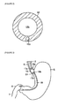
FIGURE 2) Figure 2 is a cross-sectional view of 2-2 inFigure 1 . - (
FIGURE 3) Figure 3 is a descriptive view illustrating a gastrointestinal tract tube placed in the stomach. - (
FIGURE 4) Figure 4 is a side view illustrating the gastrointestinal tract tube pertaining to a second preferred embodiment of the present disclosure. - (
FIGURE 5) Figure 5 is a side view illustrating the gastrointestinal tract tube pertaining to a third preferred embodiment of the present disclosure. - (
FIGURE 6) Figure 6 is a cross-sectional view of 6-6 inFigure 5 . - (
FIGURE 7) Figure 7 is a descriptive view illustrating the gastrointestinal tract tube inFigure 6 placed in the stomach. - The gastrointestinal tract tube pertaining to the present disclosure is provided in the tube wall of the tube body with a detention-proof lumen sandwiched at the part where the expander is provided on the outer circumferential surface of the tube body and open at a part more toward the base and more toward the tip than the part where the expander is provided on the outer circumferential surface of the tube body. Consequently, when the tip of the gastrointestinal tract tube is placed within the stomach and the expander is expanded at the gastric cardia in the transverse direction of the tube body, thus occluding the esophagus and preventing reflux of gastric contents from the stomach toward the esophagus, even if digestive juices are detained on the esophageal side of the expander, such digestive juices pass through the detention-proof lumen and enter the stomach. Detention of digestive juices in the esophagus is thus prevented.
- In such case, it is preferable that the detention-proof lumen be structured such that digestive juices, etc. cannot move from the stomach toward the esophagus. For example, when digestive juices, etc. attempt to enter the detention-proof lumen at an aperture located more toward the tip of the tube body than the expander in the detention-proof lumen, the provision of a valve occluding the aperture allows passage of digestive juices, etc. only in one direction in the detention-proof lumen. Additionally, administration of a nutritional, medicinal, or other such agent through the aperture is carried out through the main lumen of the tube body. The expander may also be an item expandable in the transverse direction of the tube body by means of a predetermined operation carried out via the working expansion lumen, and other various items may also be used, e.g., a sack-shaped item expanded by entry of a liquid or gas, or one with a structure akin to an umbrella and expanded by use of a wire or like to effect movement of a predetermined part. The tip of the main lumen may also be open at the tip of the tube body and may also be open at a side of the tip of the tube body.
- Another structural characteristic of the gastrointestinal tract tube pertaining to the present disclosure is that the main lumen is open at the tip of the tube body, and an inner tube used for supply of a liquid and extending from the base of the tube body along the inside of the main lumen and projecting from the opening is provided in the tube body.
- In such case, administration of a nutritional, medicinal, or other such agent to the stomach or intestine is carried out not by means of the main lumen of the tube body, but by means of the inner tube. Captain is procedure, once the tip of the tube body has arrived at a location just inside the stomach, the expander is expanded and thereby secured to the tube body, and the inner tube alone can be inserted into the intestinal side of the stomach or the intestine to administer a nutritional, medicinal, or other such agent. In other words, the expander is secured to the gastric cardia and prevents reflux of stomach contents from the stomach toward the esophagus, and in this state, a nutritional, medicinal, or other such agent can be administered to the stomach or intestine by advancing the tip of the inner tube to a desired location and inserting the same in the intestinal side of the stomach or the intestine.
- Yet another structural characteristic of the gastrointestinal tract tube pertaining to the present disclosure is that suction side holes are provided at a part more toward the tip than the part where the expander is provided on the outer circumferential surface of the tube body, and a suction lumen communicating from the base of the tube body to the suction side holes is provided in the tube wall of the tube body. The aperture of the suction lumen is thereby positioned at the tip part of the tube body, and consequently the inside of the stomach can be suctioned or vacuumed as needed.
- Yet another structural characteristic of the gastrointestinal tract tube pertaining to the present disclosure is that the expander comprises a balloon, and performance of a predetermined operation via the working expansion lumen comprises an operation which delivers a liquid or gas into the balloon. The esophagus or gastric cardia can thereby be occluded reliably by a simple structure. The shape of the balloon when expanded may also be spherical, barrel shaped, or various other shapes.
- In the following examples, the following symbols are used:
- 10, 20, 30) gastrointestinal tract tube; 11, 31) outer tube; 12, 22, 32) tube body; 12b, 32b) main lumen; 12c, 32c) balloon lumen; 15, 35) balloon; 16a, 16b) inlet side hole; (Text refers to "
Inlet holes outlet holes - A first preferred embodiment of the gastrointestinal tract tube pertaining to the present disclosure is described in detail using figures.
Figure 1 illustrates agastrointestinal tract tube 10 pertaining to the Preferred Embodiment, and thisgastrointestinal tract tube 10 is used to administer a nutritional agent or a medicinal agent or the like transnasally to the stomach S or intestine I (cf.Figure 3 andFigure 7 ) of a patient. Thegastrointestinal tract tube 10 comprises anouter tube 11, and aninner tube 18 provided movably within theouter tube 11. Theouter tube 11 is provided with atube body 12 comprising a long, slender resin tube;branching tubes base end 12a of thetube body 12; and aballoon 15 provided near the tip of thetube body 12 and serving as the expansion area pertaining to the present disclosure. - As shown in
Figure 2 , a large-diametermain lumen 12b is formed at the interior center of thetube body 12, and a small-diameter balloon lumen 12c is formed laterally (lower portion ofFigure 2 ) to themain lumen 12b in the tube wall of thetube body 12. Thebase end 12a of thetube body 12 is provided with two flow paths communicating with themain lumen 12b and theballoon lumen 12c. Themain lumen 12b extends from the flow path formed at the center of thebase end 12a to the tip of thetube body 12. The base end of themain lumen 12b also communicates via the flow path within thebase end 12a directly to a branchingtube 13. Aconnector 13a is formed at the back end of thebranching tube 13, and other devices or tubes or the like can be connected via theconnector 13a to thebranching tube 13 as needed. - The
balloon lumen 12c extends from one more flow path formed in thebase end 12a toward the tip of thetube body 12 and communicates with theballoon 15. The base end of theballoon lumen 12c communicates via the flow path within thebase end 12a to a branchingtube 14. The branchingtube 14 comprises a tube body of approximately the same diameter as the aforementionedbranching tube 13a, inclines from the side of thebase end 12a, and extends rearward obliquely. Aconnector 14a is formed at the back end of thebranching tube 14. A syringe or other such supply device for delivering water or air to theballoon 15 is connected to thisconnector 14a. - Operation of the supply device and delivery of water or air into the
balloon 15 expands theballoon 15 to an appropriate state. Theballoon 15 comprises an elastic, soft resin film, and itsback end 15a andtip end 15b are each secured to the outer circumferential surface of thetube body 12. During expansion and contraction, as shown inFigure 1 , the balloon assumes a state of close contact with the outer circumferential surface of thetube body 12, but when water or air is supplied, the balloon expands and assumes a spherical, cylindrical, spindle, or other such shape. -
Inlet side holes balloon 15 is provided on the outer circumferential surface of thetube body 12 and are formed in a manner maintaining 180° spacing peripherally.Outlet side holes balloon 15 is provided on the outer circumferential surface of thetube body 12 and are formed in a manner maintaining 180° spacing peripherally. Oneinlet side hole 16a andoutlet hole 16b are brought into communication by a detention-preventing lumen (not illustrated) formed in the tube wall of thetube body 12, and the otherinlet side hole 17a andoutlet hole 17b are brought into communication by a detention-preventing lumen (not illustrated) formed in the tube wall of thetube body 12. A contrast imaging line L1 comprising an X-ray opaque agent is also formed in thetube body 12 from the tip onward to the base end. - In the
inner tube 18, a tip-side portion is projected from the tip end of theouter tube 11 and disposed within theouter tube 11, and the length of projection from the tip end of theouter tube 11 can be changed by advancing or withdrawing the base end portion relative to theouter tube 11. A lumen (not illustrated) extending from the base end to the tip is also provided in theinner tube 18, and at the base end thereof, a supply device for supplying a nutritional agent, drug solution, or other such agent is connected to the lumen. - A
spindle 18b provided with aside hole 18a for nutrition supply is attached to the tip of theinner tube 18. A hole communicating with the lumen of theinner tube 18 is formed in the interior of thespindle 18b, and twoside holes 18a for nutrition supply are formed extending from the vicinity of the occluded tip (of the spindle) perpendicularly, and in respectively opposite directions. A contrast imaging line L2 comprising an X-ray opaque agent is also formed in the body of theinner tube 18 from the tip onward to the base end. - Through this structure, when a nutritional, medicinal or other such agent is administered to the stomach S or intestine I of a patient using the
gastrointestinal tract tube 10, a stylet (not illustrated) is first inserted into the space within theinner tube 18, and the adapter of the stylet is secured to the base of theinner tube 18. Next, agastrointestinal tract tube 10 in the state shown inFigure 1 is inserted together with the stylet into the nose from the side of theinner tube 18spindle 18b. Then, as shown inFigure 3 , when theouter tube 11balloon 15 has reached the gastric cardia S1, air is supplied from a supply apparatus via a branchingtube 14 andballoon lumen 12c into theballoon 15, and theballoon 15 is expanded. Theballoon 15 thus occludes the gastric cardia S1 and thereby blocks both the stomach S and esophagus E, and the tip side of theouter tube 11 is secured by means of theballoon 15. - Next, the
inner tube 18 is moved with respect to theouter tube 11, and thespindle 18b at its tip reaches the intestine side region of the stomach S or thepylorus 11, which is the boundary between the stomach S and the intestine I. Such movement of the tip of theinner tube 18 is effected smoothly by the fact thespindle 18b provided at the tip of theinner tube 18 has a predetermined weight. An adjustably-positioned stopper (not illustrated) is also attached to the outer circumferential surface of thetube body 12, and by means of this stopper, only an appropriate length of thegastrointestinal tract tube 10 is inserted. After insertion, the body of the patient is X-rayed to image and thereby confirm the position of the contrast imaging line L1 formed in thetube body 12 and the contrast imaging line L2 formed in the body of theinner tube 18. - At this point, the stylet is withdrawn from the interior of the
inner tube 18, a supply apparatus is connected to the base of theinner tube 18, and a nutritional, medicinal, or other such agent is supplied from the delivery apparatus via the lumen of theinner tube 18 to the stomach S or intestine I. At such time, the expandedballoon 15 prevents the contents of the stomach S from refluxing toward the esophagus E. Digestive juices or other such fluids also accumulate at the circumferential surface of the expandedballoon 15 on the esophagus E side, but such fluids enter each detention-proofed lumen frominlet side holes outer tube 11, pass through each detention-proofed lumen, and flow into the stomach S fromoutlet holes - Thus, in the
gastrointestinal tract tube 10 pertaining to the present preferred embodiment,inlet side holes tube body 12 more toward the base than the area where theballoon 15 is provided, andoutlet holes tube body 12 more toward the tip than the area where theballoon 15 is provided. In addition, one set ofinlet side hole 16a andoutlet hole 16b and another set ofinlet side hole 17a andoutlet hole 17b communicate respectively through the detention-proof lumens formed in the wall of thetube body 12, and theinner tube 18 is provided in theouter tube 11 movably with respect to theouter tube 11. - Consequently, positioning of the tip of the
gastrointestinal tract tube 10 within the stomach S and expanding of theballoon 15 at the gastric cardia Sl prevents the contents of the stomach S from refluxing toward the esophagus E, and at such time, digestive juices accumulating on the esophagus E side of theballoon 15 also pass through the two detention-proof lumens and enter the stomach S. As a result, detention of digestive juices in the esophagus E is prevented. And because administration of a nutritional, medicinal, or other such agent to the stomach S or intestine I is also effected by means of theinner tube 18 made movable with respect to theouter tube 11, a nutritional, medicinal, or other such agent can be administered by inserting just theinner tube 18 to a desired position toward the intestinal part of the stomach S or in the intestine I. -
Figure 4 illustrates agastrointestinal tract tube 20 pertaining to a second preferred embodiment of the present disclosure. In saidgastrointestinal tract tube 20, rather than aballoon 15, a dome-shapedexpansion dome 25 is provided as an expanding part. Saidexpansion dome 25 comprises a plurality ofstructural parts 25a made from a somewhat rigid resin, a dome-shapedsack 25b made from an elastic, flexible resin film affixed to saidstructural part 25a, and a sliding part (not illustrated) made movable along the outer circumferential surface of atube body 22. The center of thestructural parts 25a and dome-shapedsack 25b respectively is secured to the outer circumferential surface of thetube body 22, and the sliding part is connected to a wire (not illustrated) extending from a branchingtube 24 through a dome lumen (identical toballoon lumen 12c illustrated inFigure 2 ) provided in thetube body 22 and serving as a working expansion lumen pertaining to the present disclosure. - When the wire is pulled and moves the sliding part toward the base of the
tube body 22, the center portion of thestructural parts 25a is pressed, and thestructural parts 25a and dome-shapedsack 25b are pressed and spread into a dome shape. At such time, the dome-shapedsack 25b elongates into a dome shape. When the wire is pressed and moves the sliding part toward the tip of thetube body 22, contraction of the dome-shapedsack 25b impels thestructural parts 25a toward the outer circumferential surface of thetube body 22, and said parts assume a rod shape in close contact with the outer circumferential surface of thetube body 22. At such time, the contraction of the dome-shapedsack 25b prevents the tip of eachstructural part 25a from opening unexpectedly, and a separate member or mechanism intended to prevent the tip of eachstructural part 25a from opening need not be provided. - The structure of other parts of the
gastrointestinal tract tube 20 is the same as that of thegastrointestinal tract tube 10 described above. Consequently, identical parts are designated by identical symbols, and a description is omitted. Because thegastrointestinal tract tube 20 pertaining to the present preferred embodiment makes the stomach S surface side of theexpansion dome 25 concave, reflux of stomach S contents toward the esophagus E is prevented even more reliably. The operation and effect of thisgastrointestinal tract tube 20 are in other respects similar to those of thegastrointestinal tract tube 10 described above. As a variation of thegastrointestinal tract tube 20 pertaining to Preferred Embodiment 2, the orientation of theexpansion dome 25 can also be reversed. The stomach S surface of theexpansion dome 25 is thereby made convex and occludes the gastric cardia S1 in a covering fashion, and reflux of stomach S contents toward the esophagus E is prevented. Likewise, resistance of theexpansion dome 25 during insertion of thegastrointestinal tract tube 20 is also prevented. -
Figure 5 illustrates agastrointestinal tract tube 30 pertaining to a third preferred embodiment of the present disclosure. In saidgastrointestinal tract tube 30, anouter tube 31 is provided with atube body 32 comprising a long, slender tube; three branchingtubes base 32a of thetube body 32; and aballoon 35 provided from the tip of thetube body 32 toward the base at an area separated only by a predetermined distance. As shown inFigure 6 , a large-diametermain lumen 32b is formed at the interior center of thetube body 32, and aballoon lumen 32c and twosuction lumens 32d are formed at the tube wall of thetube body 32. - The
base 32a of thetube body 32 is provided with three flow paths communicating with themain lumen 32b,balloon lumen 32c, andsuction lumens 32d. Themain lumen 32b communicates with a branchingtube 33 via a central flow path within thebase 32a, and theballoon lumen 32c communicates with another branchingtube 34 via another flow path formed in thebase 32a. Thesuction lumens 32d communicate with another branchingtube 36 via the remaining other flow path formed in thebase 32a. One branchingtube 33 extends straight from thebase 32a, and the other branchingtubes base 32a and extend obliquely backward in opposite directions. A suction device or other such suction apparatus is connected to the back end of one branchingtube 36 via aconnector 36a. - The part of the
tube body 32 more toward the tip than the part where theballoon 35 is provided is made longer than the aforementioned tip part of thetube body 12 of thegastrointestinal tract tube 10, and on its outer circumferential surface there open a plurality of side holes 37 for suction which communicate with thesuction lumens 32d. In other words, saidouter tube 31 is one formed such that a branchingtube 36 andsuction lumens 32d are provided in the aforementionedouter tube 11 of thegastrointestinal tract tube 10, and in which there is one additional flow path in thebase 32a which extends along the tip part of thetube body 32, and in said part there are formed a plurality of suction side holes 37 which communicate withsuction lumens 32d. The structure of other parts of saidgastrointestinal tract tube 30 is identical to that of thegastrointestinal tract tube 10 described above. Consequently, identical parts are designated by identical symbols, and a description is omitted. - When this
gastrointestinal tract tube 30 is used to administer a nutritional, medicinal, or other such agent to the stomach S or intestine I of a patient, as when thegastrointestinal tract tube 10 described above is used, thegastrointestinal tract tube 30 is placed in the stomach S. In such instance, as shown inFigure 7 , the tip part of thetube body 32 is positioned at the intestinal side of the stomach S. If, for this purpose, the pressure within the stomach S must be reduced or liquids etc. in the stomach S must be removed in order to prevent reflux of the stomach S contents toward the esophagus E, a suction apparatus can be operated to suction the interior of the stomach S. Liquids or gases within the stomach S will thereby enter thesuction lumens 32d from the suction side holes 37 and will be suctioned from the branchingtube 36 into the suction apparatus. The operation and effect of thegastrointestinal tract tube 30 are in other respects similar to those of thegastrointestinal tract tube 10 described above. - As another preferred embodiment, the
expansion dome 25 in the second preferred embodiment described above can be used in lieu of theballoon 35 of thegastrointestinal tract tube 30 described above. In such instance as well, an operation and effect equivalent to those of thegastrointestinal tract tube 30 are obtained. As yet another preferred embodiment, an item wherein theinner tube 18 is removed from any of thegastrointestinal tract tubes tube connector main lumen outer tube - The therapeutic tube pertaining to the present disclosure is also not limited to the respective preferred embodiments described above and can be implemented with changes as appropriate. For example, in each of the preferred embodiments described above, the
outlet side holes tube body outlet side holes outlet side holes outlet side holes outlet side holes outlet side holes - Movement of digestive juices, etc. from the stomach S toward the esophagus E can also be prevented by providing two tabs at the apertures of the
outlet side holes outlet side holes balloon expansion dome 25 and may also be one which expands transversely in thetube body
Claims (4)
- A gastrointestinal tract tube provided with a tube body provided with a main lumen extending from a base part to a tip part and a lumen for expansion oriented from the base part toward the tip, and with an expander provided on the outer circumferential surface of the tube body which is expanded in the transverse direction of the tube body by the lumen for expansion; characterized in that side holes are provided respectively at a part more toward the base than the part where the expander is provided on the outer circumferential surface of the tube body, and at a part more toward the tip than the part where the expander is provided on the outer circumferential surface of the tube body; and a detention-proof lumen communicating with the side holes is provided in the tube wall of the tube body.
- The gastrointestinal tract tube according to claim 1, characterized in that the main lumen is open at the tip of the tube body, and an inner tube used for supply of a liquid and extending from the base of the tube body along the inside of the main lumen and projecting from the opening is provided in the tube body.
- The gastrointestinal tract tube according to any of claims 1 or 2, characterized in that suction side holes are provided at a part more toward the tip than the part where the expander is provided on the outer circumferential surface of the tube body, and a suction lumen communicating from the base of the tube body to the suction side holes is provided in the tube wall of the tube body.
- The gastrointestinal tract tube according to any of claims 1 to 3, characterized in that the expander comprises a balloon, and the lumen for expansion delivers a liquid or gas into the balloon.
Applications Claiming Priority (1)
| Application Number | Priority Date | Filing Date | Title |
|---|---|---|---|
| JP2009219888A JP2011067304A (en) | 2009-09-25 | 2009-09-25 | Tube for gastrointestinal tract |
Publications (4)
| Publication Number | Publication Date |
|---|---|
| EP2301512A2 true EP2301512A2 (en) | 2011-03-30 |
| EP2301512A3 EP2301512A3 (en) | 2011-11-30 |
| EP2301512B1 EP2301512B1 (en) | 2012-12-05 |
| EP2301512B8 EP2301512B8 (en) | 2013-02-13 |
Family
ID=43242410
Family Applications (1)
| Application Number | Title | Priority Date | Filing Date |
|---|---|---|---|
| EP10009769A Active EP2301512B8 (en) | 2009-09-25 | 2010-09-17 | Tube for gastrointestinal tract |
Country Status (3)
| Country | Link |
|---|---|
| US (1) | US20110218493A1 (en) |
| EP (1) | EP2301512B8 (en) |
| JP (1) | JP2011067304A (en) |
Cited By (10)
| Publication number | Priority date | Publication date | Assignee | Title |
|---|---|---|---|---|
| WO2013012774A1 (en) * | 2011-07-17 | 2013-01-24 | Klein, David | Nasogastric tube |
| CN103006443A (en) * | 2013-01-04 | 2013-04-03 | 法志强 | Stomach-intestine nutrient canal capable of draining reflux liquid |
| US20140188080A1 (en) * | 2011-07-17 | 2014-07-03 | Turbo Seal L.P. | Nasogastric tube |
| CN104994808A (en) * | 2013-01-07 | 2015-10-21 | Gi动力公司 | Jejunal feeding tube and delivery system |
| US20160158111A1 (en) * | 2011-07-17 | 2016-06-09 | Nutriseal L.P. | Nasogastric tube |
| US9827169B2 (en) | 2011-07-17 | 2017-11-28 | Nutriseal L.P. | Nasogastric tube with camera |
| US10376447B2 (en) | 2015-02-02 | 2019-08-13 | Envizion Medical Ltd. | Enteral feeding system with controlled reflux preventive vacuum sealing |
| US10695269B2 (en) | 2014-08-14 | 2020-06-30 | Envizion Medical Ltd. | Nasogastric tube |
| CN113317994A (en) * | 2021-06-22 | 2021-08-31 | 四川省医学科学院·四川省人民医院 | Anti-reflux stomach tube |
| US12667524B2 (en) | 2014-06-26 | 2026-06-30 | Envue Medical Holdings, Corp. | Nasogastric tube |
Families Citing this family (7)
| Publication number | Priority date | Publication date | Assignee | Title |
|---|---|---|---|---|
| JP6153133B2 (en) | 2010-12-15 | 2017-06-28 | コロスパン リミテッドColospan Ltd. | System and method for bypassing an anastomosis site |
| WO2016059634A2 (en) | 2014-10-14 | 2016-04-21 | Cologuard Ltd. | Apparatus for delivering a device to a hollow organ |
| US10272228B1 (en) | 2016-05-17 | 2019-04-30 | Aspisafe Solutions Inc. | Expandable intubation assemblies |
| US20180228698A1 (en) * | 2017-02-13 | 2018-08-16 | New York University | Double Balloon Floating Feeding Jejunostomy Tube |
| CN106860026A (en) * | 2017-03-03 | 2017-06-20 | 浙江简成医疗科技有限公司 | A kind of multi-functional connector of Nasal gastrointestinal tube |
| US11259858B1 (en) * | 2018-02-06 | 2022-03-01 | Jason RAHIMZADEH | Endoscopy tube and device for cryotherapy |
| CN114504410B (en) * | 2022-03-09 | 2026-02-06 | 烟台光华医院有限公司 | Adjustable esophagus cardiac particle bracket and stomach tube comprising same |
Family Cites Families (9)
| Publication number | Priority date | Publication date | Assignee | Title |
|---|---|---|---|---|
| US4180076A (en) * | 1977-05-06 | 1979-12-25 | Betancourt Victor M | Nasogastric catheters |
| US4356824A (en) * | 1980-07-30 | 1982-11-02 | Vazquez Richard M | Multiple lumen gastrostomy tube |
| JPH0314196Y2 (en) * | 1984-12-19 | 1991-03-29 | ||
| US4983167A (en) * | 1988-11-23 | 1991-01-08 | Harvinder Sahota | Balloon catheters |
| ES2090569T3 (en) * | 1991-06-03 | 1996-10-16 | Schneider Europ Ag | CATHETER SYSTEM FOR MECHANICAL DILATION OF CORONARY STENOSIS. |
| US5314409A (en) * | 1993-03-11 | 1994-05-24 | Uva Patents Foundation | Catheter for esophageal perfusion |
| US5507726A (en) * | 1994-03-15 | 1996-04-16 | Cordis Corporation | Perfusion catheter with moving tube |
| CA2265607C (en) * | 1996-09-10 | 2002-07-02 | Fred G. Gobel | Stomach probe |
| JP4381693B2 (en) * | 2003-02-21 | 2009-12-09 | 川澄化学工業株式会社 | Balloon catheter |
-
2009
- 2009-09-25 JP JP2009219888A patent/JP2011067304A/en active Pending
-
2010
- 2010-09-14 US US12/881,295 patent/US20110218493A1/en not_active Abandoned
- 2010-09-17 EP EP10009769A patent/EP2301512B8/en active Active
Non-Patent Citations (1)
| Title |
|---|
| None |
Cited By (18)
| Publication number | Priority date | Publication date | Assignee | Title |
|---|---|---|---|---|
| US9839584B2 (en) * | 2011-07-17 | 2017-12-12 | Nutriseal Limited Partnership | Nasogastric tube |
| US10646406B2 (en) | 2011-07-17 | 2020-05-12 | Envizion Medical Ltd. | Nasogastric tube |
| US20130310806A1 (en) * | 2011-07-17 | 2013-11-21 | Turbo Seal L.P. | Nasogastric Tube |
| US20140188080A1 (en) * | 2011-07-17 | 2014-07-03 | Turbo Seal L.P. | Nasogastric tube |
| WO2013012774A1 (en) * | 2011-07-17 | 2013-01-24 | Klein, David | Nasogastric tube |
| US10350145B2 (en) | 2011-07-17 | 2019-07-16 | Envizion Medical Ltd. | Nasogastric tube |
| US20160158111A1 (en) * | 2011-07-17 | 2016-06-09 | Nutriseal L.P. | Nasogastric tube |
| US20170239148A1 (en) * | 2011-07-17 | 2017-08-24 | Nutriseal L.P. | Nasogastric tube |
| US9789029B2 (en) * | 2011-07-17 | 2017-10-17 | Nutriseal Limited Partnership | Nasogastric tube |
| US9827169B2 (en) | 2011-07-17 | 2017-11-28 | Nutriseal L.P. | Nasogastric tube with camera |
| CN103006443B (en) * | 2013-01-04 | 2015-04-08 | 法志强 | Stomach-intestine nutrient canal capable of draining reflux liquid |
| CN103006443A (en) * | 2013-01-04 | 2013-04-03 | 法志强 | Stomach-intestine nutrient canal capable of draining reflux liquid |
| CN104994808A (en) * | 2013-01-07 | 2015-10-21 | Gi动力公司 | Jejunal feeding tube and delivery system |
| US12667524B2 (en) | 2014-06-26 | 2026-06-30 | Envue Medical Holdings, Corp. | Nasogastric tube |
| US10695269B2 (en) | 2014-08-14 | 2020-06-30 | Envizion Medical Ltd. | Nasogastric tube |
| US10376447B2 (en) | 2015-02-02 | 2019-08-13 | Envizion Medical Ltd. | Enteral feeding system with controlled reflux preventive vacuum sealing |
| CN113317994A (en) * | 2021-06-22 | 2021-08-31 | 四川省医学科学院·四川省人民医院 | Anti-reflux stomach tube |
| CN113317994B (en) * | 2021-06-22 | 2023-06-16 | 四川省医学科学院·四川省人民医院 | Anti-reflux stomach tube |
Also Published As
| Publication number | Publication date |
|---|---|
| EP2301512B1 (en) | 2012-12-05 |
| US20110218493A1 (en) | 2011-09-08 |
| EP2301512B8 (en) | 2013-02-13 |
| EP2301512A3 (en) | 2011-11-30 |
| JP2011067304A (en) | 2011-04-07 |
Similar Documents
| Publication | Publication Date | Title |
|---|---|---|
| EP2301512B1 (en) | Tube for gastrointestinal tract | |
| JP5184512B2 (en) | Supply device, bolster apparatus, and method for producing the same | |
| US5318530A (en) | Gastrointestinal tube with inflatable bolus | |
| JP2005527333A (en) | Low contour shape transpyloric jejunostomy system | |
| JP2004504866A (en) | Low height intestinal fistula forming device | |
| US5871467A (en) | Post-pyloric feeding tubes | |
| CN104994808B (en) | jejunal feeding tube and delivery system | |
| US20040034320A1 (en) | Anti-reflux feeding tube | |
| WO2007095541A2 (en) | Plural lumen gastrostomy tube insert for placement into the duodenum and method of monitoring and managing feeding | |
| JP5907746B2 (en) | Low profile GJ feeding device | |
| CN113453741A (en) | Systems, apparatus and methods for placing a guidewire for a gastrostomy catheter | |
| US6659974B1 (en) | Single lumen gastro-intestinal feeding-decompression tubes | |
| JP2001029434A (en) | Enteral gastroenterostomy catheter | |
| CN204562994U (en) | The two merit pipe of gastrointestinal decompression duodenal nutrition | |
| US20190231647A1 (en) | Enteral feeding tube with inflatable cuff | |
| CN105920721A (en) | Nasointestinal tube | |
| CN113057777B (en) | Weight-losing device with intragastric support | |
| JP3153651U (en) | Nasal tube feeding catheter with drop-off prevention cuff | |
| CN110575610B (en) | PTCD drainage-based bile-transfusion intestinal tract kit | |
| JP2809765B2 (en) | Intestinal insertion catheter | |
| CN205460386U (en) | A two sacculus pipes for operation of stomach fistulization | |
| JPH08215303A (en) | Intestinal catheter | |
| JPH0539704Y2 (en) | ||
| JP2513343Y2 (en) | Catheter for intestinal insertion | |
| JPH0748269Y2 (en) | Gastrointestinal catheter |
Legal Events
| Date | Code | Title | Description |
|---|---|---|---|
| PUAI | Public reference made under article 153(3) epc to a published international application that has entered the european phase |
Free format text: ORIGINAL CODE: 0009012 |
|
| AK | Designated contracting states |
Kind code of ref document: A2 Designated state(s): AL AT BE BG CH CY CZ DE DK EE ES FI FR GB GR HR HU IE IS IT LI LT LU LV MC MK MT NL NO PL PT RO SE SI SK SM TR |
|
| AX | Request for extension of the european patent |
Extension state: BA ME RS |
|
| PUAL | Search report despatched |
Free format text: ORIGINAL CODE: 0009013 |
|
| AK | Designated contracting states |
Kind code of ref document: A3 Designated state(s): AL AT BE BG CH CY CZ DE DK EE ES FI FR GB GR HR HU IE IS IT LI LT LU LV MC MK MT NL NO PL PT RO SE SI SK SM TR |
|
| AX | Request for extension of the european patent |
Extension state: BA ME RS |
|
| RIC1 | Information provided on ipc code assigned before grant |
Ipc: A61J 15/00 20060101AFI20111025BHEP |
|
| 17P | Request for examination filed |
Effective date: 20120308 |
|
| GRAP | Despatch of communication of intention to grant a patent |
Free format text: ORIGINAL CODE: EPIDOSNIGR1 |
|
| GRAS | Grant fee paid |
Free format text: ORIGINAL CODE: EPIDOSNIGR3 |
|
| GRAA | (expected) grant |
Free format text: ORIGINAL CODE: 0009210 |
|
| AK | Designated contracting states |
Kind code of ref document: B1 Designated state(s): AL AT BE BG CH CY CZ DE DK EE ES FI FR GB GR HR HU IE IS IT LI LT LU LV MC MK MT NL NO PL PT RO SE SI SK SM TR |
|
| REG | Reference to a national code |
Ref country code: GB Ref legal event code: FG4D |
|
| RAP2 | Party data changed (patent owner data changed or rights of a patent transferred) |
Owner name: COVIDIEN LP |
|
| REG | Reference to a national code |
Ref country code: CH Ref legal event code: EP |
|
| REG | Reference to a national code |
Ref country code: AT Ref legal event code: REF Ref document number: 586862 Country of ref document: AT Kind code of ref document: T Effective date: 20121215 |
|
| REG | Reference to a national code |
Ref country code: IE Ref legal event code: FG4D |
|
| REG | Reference to a national code |
Ref country code: DE Ref legal event code: R096 Ref document number: 602010003887 Country of ref document: DE Effective date: 20130131 |
|
| REG | Reference to a national code |
Ref country code: DE Ref legal event code: R081 Ref document number: 602010003887 Country of ref document: DE Owner name: COVIDIEN LP, US Free format text: FORMER OWNER: TYCO HEALTHCARE GROUP LP, MANSFIELD, US Effective date: 20130116 Ref country code: DE Ref legal event code: R081 Ref document number: 602010003887 Country of ref document: DE Owner name: COVIDIEN LP, MANSFIELD, US Free format text: FORMER OWNER: TYCO HEALTHCARE GROUP LP, MANSFIELD, MASS., US Effective date: 20130116 |
|
| REG | Reference to a national code |
Ref country code: AT Ref legal event code: MK05 Ref document number: 586862 Country of ref document: AT Kind code of ref document: T Effective date: 20121205 |
|
| PG25 | Lapsed in a contracting state [announced via postgrant information from national office to epo] |
Ref country code: NO Free format text: LAPSE BECAUSE OF FAILURE TO SUBMIT A TRANSLATION OF THE DESCRIPTION OR TO PAY THE FEE WITHIN THE PRESCRIBED TIME-LIMIT Effective date: 20130305 Ref country code: ES Free format text: LAPSE BECAUSE OF FAILURE TO SUBMIT A TRANSLATION OF THE DESCRIPTION OR TO PAY THE FEE WITHIN THE PRESCRIBED TIME-LIMIT Effective date: 20130316 Ref country code: LT Free format text: LAPSE BECAUSE OF FAILURE TO SUBMIT A TRANSLATION OF THE DESCRIPTION OR TO PAY THE FEE WITHIN THE PRESCRIBED TIME-LIMIT Effective date: 20121205 Ref country code: FI Free format text: LAPSE BECAUSE OF FAILURE TO SUBMIT A TRANSLATION OF THE DESCRIPTION OR TO PAY THE FEE WITHIN THE PRESCRIBED TIME-LIMIT Effective date: 20121205 Ref country code: HR Free format text: LAPSE BECAUSE OF FAILURE TO SUBMIT A TRANSLATION OF THE DESCRIPTION OR TO PAY THE FEE WITHIN THE PRESCRIBED TIME-LIMIT Effective date: 20121205 Ref country code: SE Free format text: LAPSE BECAUSE OF FAILURE TO SUBMIT A TRANSLATION OF THE DESCRIPTION OR TO PAY THE FEE WITHIN THE PRESCRIBED TIME-LIMIT Effective date: 20121205 |
|
| REG | Reference to a national code |
Ref country code: NL Ref legal event code: VDEP Effective date: 20121205 |
|
| REG | Reference to a national code |
Ref country code: LT Ref legal event code: MG4D |
|
| PG25 | Lapsed in a contracting state [announced via postgrant information from national office to epo] |
Ref country code: GR Free format text: LAPSE BECAUSE OF FAILURE TO SUBMIT A TRANSLATION OF THE DESCRIPTION OR TO PAY THE FEE WITHIN THE PRESCRIBED TIME-LIMIT Effective date: 20130306 Ref country code: PL Free format text: LAPSE BECAUSE OF FAILURE TO SUBMIT A TRANSLATION OF THE DESCRIPTION OR TO PAY THE FEE WITHIN THE PRESCRIBED TIME-LIMIT Effective date: 20121205 Ref country code: LV Free format text: LAPSE BECAUSE OF FAILURE TO SUBMIT A TRANSLATION OF THE DESCRIPTION OR TO PAY THE FEE WITHIN THE PRESCRIBED TIME-LIMIT Effective date: 20121205 Ref country code: SI Free format text: LAPSE BECAUSE OF FAILURE TO SUBMIT A TRANSLATION OF THE DESCRIPTION OR TO PAY THE FEE WITHIN THE PRESCRIBED TIME-LIMIT Effective date: 20121205 |
|
| PG25 | Lapsed in a contracting state [announced via postgrant information from national office to epo] |
Ref country code: AT Free format text: LAPSE BECAUSE OF FAILURE TO SUBMIT A TRANSLATION OF THE DESCRIPTION OR TO PAY THE FEE WITHIN THE PRESCRIBED TIME-LIMIT Effective date: 20121205 |
|
| PG25 | Lapsed in a contracting state [announced via postgrant information from national office to epo] |
Ref country code: IS Free format text: LAPSE BECAUSE OF FAILURE TO SUBMIT A TRANSLATION OF THE DESCRIPTION OR TO PAY THE FEE WITHIN THE PRESCRIBED TIME-LIMIT Effective date: 20130405 Ref country code: CZ Free format text: LAPSE BECAUSE OF FAILURE TO SUBMIT A TRANSLATION OF THE DESCRIPTION OR TO PAY THE FEE WITHIN THE PRESCRIBED TIME-LIMIT Effective date: 20121205 Ref country code: BE Free format text: LAPSE BECAUSE OF FAILURE TO SUBMIT A TRANSLATION OF THE DESCRIPTION OR TO PAY THE FEE WITHIN THE PRESCRIBED TIME-LIMIT Effective date: 20121205 Ref country code: BG Free format text: LAPSE BECAUSE OF FAILURE TO SUBMIT A TRANSLATION OF THE DESCRIPTION OR TO PAY THE FEE WITHIN THE PRESCRIBED TIME-LIMIT Effective date: 20130305 Ref country code: SK Free format text: LAPSE BECAUSE OF FAILURE TO SUBMIT A TRANSLATION OF THE DESCRIPTION OR TO PAY THE FEE WITHIN THE PRESCRIBED TIME-LIMIT Effective date: 20121205 Ref country code: EE Free format text: LAPSE BECAUSE OF FAILURE TO SUBMIT A TRANSLATION OF THE DESCRIPTION OR TO PAY THE FEE WITHIN THE PRESCRIBED TIME-LIMIT Effective date: 20121205 |
|
| PG25 | Lapsed in a contracting state [announced via postgrant information from national office to epo] |
Ref country code: RO Free format text: LAPSE BECAUSE OF FAILURE TO SUBMIT A TRANSLATION OF THE DESCRIPTION OR TO PAY THE FEE WITHIN THE PRESCRIBED TIME-LIMIT Effective date: 20121205 Ref country code: NL Free format text: LAPSE BECAUSE OF FAILURE TO SUBMIT A TRANSLATION OF THE DESCRIPTION OR TO PAY THE FEE WITHIN THE PRESCRIBED TIME-LIMIT Effective date: 20121205 Ref country code: PT Free format text: LAPSE BECAUSE OF FAILURE TO SUBMIT A TRANSLATION OF THE DESCRIPTION OR TO PAY THE FEE WITHIN THE PRESCRIBED TIME-LIMIT Effective date: 20130405 |
|
| PLBE | No opposition filed within time limit |
Free format text: ORIGINAL CODE: 0009261 |
|
| STAA | Information on the status of an ep patent application or granted ep patent |
Free format text: STATUS: NO OPPOSITION FILED WITHIN TIME LIMIT |
|
| PG25 | Lapsed in a contracting state [announced via postgrant information from national office to epo] |
Ref country code: DK Free format text: LAPSE BECAUSE OF FAILURE TO SUBMIT A TRANSLATION OF THE DESCRIPTION OR TO PAY THE FEE WITHIN THE PRESCRIBED TIME-LIMIT Effective date: 20121205 |
|
| 26N | No opposition filed |
Effective date: 20130906 |
|
| PG25 | Lapsed in a contracting state [announced via postgrant information from national office to epo] |
Ref country code: CY Free format text: LAPSE BECAUSE OF FAILURE TO SUBMIT A TRANSLATION OF THE DESCRIPTION OR TO PAY THE FEE WITHIN THE PRESCRIBED TIME-LIMIT Effective date: 20121205 |
|
| PG25 | Lapsed in a contracting state [announced via postgrant information from national office to epo] |
Ref country code: IT Free format text: LAPSE BECAUSE OF FAILURE TO SUBMIT A TRANSLATION OF THE DESCRIPTION OR TO PAY THE FEE WITHIN THE PRESCRIBED TIME-LIMIT Effective date: 20121205 |
|
| REG | Reference to a national code |
Ref country code: DE Ref legal event code: R097 Ref document number: 602010003887 Country of ref document: DE Effective date: 20130906 |
|
| PG25 | Lapsed in a contracting state [announced via postgrant information from national office to epo] |
Ref country code: MC Free format text: LAPSE BECAUSE OF FAILURE TO SUBMIT A TRANSLATION OF THE DESCRIPTION OR TO PAY THE FEE WITHIN THE PRESCRIBED TIME-LIMIT Effective date: 20121205 |
|
| REG | Reference to a national code |
Ref country code: IE Ref legal event code: MM4A |
|
| PG25 | Lapsed in a contracting state [announced via postgrant information from national office to epo] |
Ref country code: IE Free format text: LAPSE BECAUSE OF NON-PAYMENT OF DUE FEES Effective date: 20130917 |
|
| REG | Reference to a national code |
Ref country code: CH Ref legal event code: PL |
|
| PG25 | Lapsed in a contracting state [announced via postgrant information from national office to epo] |
Ref country code: SM Free format text: LAPSE BECAUSE OF FAILURE TO SUBMIT A TRANSLATION OF THE DESCRIPTION OR TO PAY THE FEE WITHIN THE PRESCRIBED TIME-LIMIT Effective date: 20121205 |
|
| PG25 | Lapsed in a contracting state [announced via postgrant information from national office to epo] |
Ref country code: TR Free format text: LAPSE BECAUSE OF FAILURE TO SUBMIT A TRANSLATION OF THE DESCRIPTION OR TO PAY THE FEE WITHIN THE PRESCRIBED TIME-LIMIT Effective date: 20121205 Ref country code: MT Free format text: LAPSE BECAUSE OF FAILURE TO SUBMIT A TRANSLATION OF THE DESCRIPTION OR TO PAY THE FEE WITHIN THE PRESCRIBED TIME-LIMIT Effective date: 20121205 |
|
| PG25 | Lapsed in a contracting state [announced via postgrant information from national office to epo] |
Ref country code: LI Free format text: LAPSE BECAUSE OF NON-PAYMENT OF DUE FEES Effective date: 20140930 Ref country code: CH Free format text: LAPSE BECAUSE OF NON-PAYMENT OF DUE FEES Effective date: 20140930 Ref country code: HU Free format text: LAPSE BECAUSE OF FAILURE TO SUBMIT A TRANSLATION OF THE DESCRIPTION OR TO PAY THE FEE WITHIN THE PRESCRIBED TIME-LIMIT; INVALID AB INITIO Effective date: 20100917 Ref country code: LU Free format text: LAPSE BECAUSE OF NON-PAYMENT OF DUE FEES Effective date: 20130917 Ref country code: MK Free format text: LAPSE BECAUSE OF FAILURE TO SUBMIT A TRANSLATION OF THE DESCRIPTION OR TO PAY THE FEE WITHIN THE PRESCRIBED TIME-LIMIT Effective date: 20121205 |
|
| REG | Reference to a national code |
Ref country code: FR Ref legal event code: PLFP Year of fee payment: 7 |
|
| REG | Reference to a national code |
Ref country code: FR Ref legal event code: PLFP Year of fee payment: 8 |
|
| REG | Reference to a national code |
Ref country code: FR Ref legal event code: PLFP Year of fee payment: 9 |
|
| PG25 | Lapsed in a contracting state [announced via postgrant information from national office to epo] |
Ref country code: AL Free format text: LAPSE BECAUSE OF FAILURE TO SUBMIT A TRANSLATION OF THE DESCRIPTION OR TO PAY THE FEE WITHIN THE PRESCRIBED TIME-LIMIT Effective date: 20121205 |
|
| PGFP | Annual fee paid to national office [announced via postgrant information from national office to epo] |
Ref country code: DE Payment date: 20250929 Year of fee payment: 16 |
|
| PGFP | Annual fee paid to national office [announced via postgrant information from national office to epo] |
Ref country code: GB Payment date: 20250929 Year of fee payment: 16 |
|
| PGFP | Annual fee paid to national office [announced via postgrant information from national office to epo] |
Ref country code: FR Payment date: 20250925 Year of fee payment: 16 |