EP2300787B1 - Sensor and control unit for flow control and a method for controlled delivery of fluid - Google Patents
Sensor and control unit for flow control and a method for controlled delivery of fluid Download PDFInfo
- Publication number
- EP2300787B1 EP2300787B1 EP09786497.9A EP09786497A EP2300787B1 EP 2300787 B1 EP2300787 B1 EP 2300787B1 EP 09786497 A EP09786497 A EP 09786497A EP 2300787 B1 EP2300787 B1 EP 2300787B1
- Authority
- EP
- European Patent Office
- Prior art keywords
- sensor
- fluid
- control unit
- heating element
- channel
- Prior art date
- Legal status (The legal status is an assumption and is not a legal conclusion. Google has not performed a legal analysis and makes no representation as to the accuracy of the status listed.)
- Not-in-force
Links
- 239000012530 fluid Substances 0.000 title claims description 84
- 238000000034 method Methods 0.000 title claims description 17
- 238000010438 heat treatment Methods 0.000 claims description 80
- 238000005259 measurement Methods 0.000 claims description 42
- 230000005670 electromagnetic radiation Effects 0.000 claims description 21
- 229940079593 drug Drugs 0.000 claims description 12
- 239000003814 drug Substances 0.000 claims description 12
- 239000007788 liquid Substances 0.000 claims description 10
- 238000012544 monitoring process Methods 0.000 description 7
- 238000001990 intravenous administration Methods 0.000 description 5
- 230000008901 benefit Effects 0.000 description 4
- 238000001802 infusion Methods 0.000 description 4
- 239000000463 material Substances 0.000 description 4
- 239000004642 Polyimide Substances 0.000 description 3
- 230000005484 gravity Effects 0.000 description 3
- 238000011144 upstream manufacturing Methods 0.000 description 3
- 230000002485 urinary effect Effects 0.000 description 3
- PXFBZOLANLWPMH-UHFFFAOYSA-N 16-Epiaffinine Natural products C1C(C2=CC=CC=C2N2)=C2C(=O)CC2C(=CC)CN(C)C1C2CO PXFBZOLANLWPMH-UHFFFAOYSA-N 0.000 description 2
- 206010002091 Anaesthesia Diseases 0.000 description 2
- 230000037005 anaesthesia Effects 0.000 description 2
- 238000004146 energy storage Methods 0.000 description 2
- 238000004519 manufacturing process Methods 0.000 description 2
- 238000012806 monitoring device Methods 0.000 description 2
- 239000000758 substrate Substances 0.000 description 2
- 238000002940 Newton-Raphson method Methods 0.000 description 1
- 238000004458 analytical method Methods 0.000 description 1
- 238000013459 approach Methods 0.000 description 1
- 230000036772 blood pressure Effects 0.000 description 1
- 238000012986 modification Methods 0.000 description 1
- 230000004048 modification Effects 0.000 description 1
- 235000016236 parenteral nutrition Nutrition 0.000 description 1
- 239000004033 plastic Substances 0.000 description 1
- 230000002035 prolonged effect Effects 0.000 description 1
- 238000004064 recycling Methods 0.000 description 1
- 230000029058 respiratory gaseous exchange Effects 0.000 description 1
- 230000035939 shock Effects 0.000 description 1
- 239000000126 substance Substances 0.000 description 1
- 230000001225 therapeutic effect Effects 0.000 description 1
- XLYOFNOQVPJJNP-UHFFFAOYSA-N water Substances O XLYOFNOQVPJJNP-UHFFFAOYSA-N 0.000 description 1
Images



Classifications
-
- G—PHYSICS
- G01—MEASURING; TESTING
- G01F—MEASURING VOLUME, VOLUME FLOW, MASS FLOW OR LIQUID LEVEL; METERING BY VOLUME
- G01F1/00—Measuring the volume flow or mass flow of fluid or fluent solid material wherein the fluid passes through a meter in a continuous flow
- G01F1/68—Measuring the volume flow or mass flow of fluid or fluent solid material wherein the fluid passes through a meter in a continuous flow by using thermal effects
- G01F1/684—Structural arrangements; Mounting of elements, e.g. in relation to fluid flow
- G01F1/688—Structural arrangements; Mounting of elements, e.g. in relation to fluid flow using a particular type of heating, cooling or sensing element
- G01F1/6888—Thermoelectric elements, e.g. thermocouples, thermopiles
-
- A—HUMAN NECESSITIES
- A61—MEDICAL OR VETERINARY SCIENCE; HYGIENE
- A61M—DEVICES FOR INTRODUCING MEDIA INTO, OR ONTO, THE BODY; DEVICES FOR TRANSDUCING BODY MEDIA OR FOR TAKING MEDIA FROM THE BODY; DEVICES FOR PRODUCING OR ENDING SLEEP OR STUPOR
- A61M5/00—Devices for bringing media into the body in a subcutaneous, intra-vascular or intramuscular way; Accessories therefor, e.g. filling or cleaning devices, arm-rests
- A61M5/14—Infusion devices, e.g. infusing by gravity; Blood infusion; Accessories therefor
- A61M5/168—Means for controlling media flow to the body or for metering media to the body, e.g. drip meters, counters ; Monitoring media flow to the body
- A61M5/16886—Means for controlling media flow to the body or for metering media to the body, e.g. drip meters, counters ; Monitoring media flow to the body for measuring fluid flow rate, i.e. flowmeters
-
- G—PHYSICS
- G01—MEASURING; TESTING
- G01F—MEASURING VOLUME, VOLUME FLOW, MASS FLOW OR LIQUID LEVEL; METERING BY VOLUME
- G01F1/00—Measuring the volume flow or mass flow of fluid or fluent solid material wherein the fluid passes through a meter in a continuous flow
- G01F1/68—Measuring the volume flow or mass flow of fluid or fluent solid material wherein the fluid passes through a meter in a continuous flow by using thermal effects
- G01F1/684—Structural arrangements; Mounting of elements, e.g. in relation to fluid flow
- G01F1/6847—Structural arrangements; Mounting of elements, e.g. in relation to fluid flow where sensing or heating elements are not disturbing the fluid flow, e.g. elements mounted outside the flow duct
-
- G—PHYSICS
- G01—MEASURING; TESTING
- G01F—MEASURING VOLUME, VOLUME FLOW, MASS FLOW OR LIQUID LEVEL; METERING BY VOLUME
- G01F1/00—Measuring the volume flow or mass flow of fluid or fluent solid material wherein the fluid passes through a meter in a continuous flow
- G01F1/68—Measuring the volume flow or mass flow of fluid or fluent solid material wherein the fluid passes through a meter in a continuous flow by using thermal effects
- G01F1/696—Circuits therefor, e.g. constant-current flow meters
-
- G—PHYSICS
- G01—MEASURING; TESTING
- G01F—MEASURING VOLUME, VOLUME FLOW, MASS FLOW OR LIQUID LEVEL; METERING BY VOLUME
- G01F15/00—Details of, or accessories for, apparatus of groups G01F1/00 - G01F13/00 insofar as such details or appliances are not adapted to particular types of such apparatus
- G01F15/005—Valves
-
- G—PHYSICS
- G01—MEASURING; TESTING
- G01F—MEASURING VOLUME, VOLUME FLOW, MASS FLOW OR LIQUID LEVEL; METERING BY VOLUME
- G01F15/00—Details of, or accessories for, apparatus of groups G01F1/00 - G01F13/00 insofar as such details or appliances are not adapted to particular types of such apparatus
- G01F15/14—Casings, e.g. of special material
-
- A—HUMAN NECESSITIES
- A61—MEDICAL OR VETERINARY SCIENCE; HYGIENE
- A61M—DEVICES FOR INTRODUCING MEDIA INTO, OR ONTO, THE BODY; DEVICES FOR TRANSDUCING BODY MEDIA OR FOR TAKING MEDIA FROM THE BODY; DEVICES FOR PRODUCING OR ENDING SLEEP OR STUPOR
- A61M2205/00—General characteristics of the apparatus
- A61M2205/33—Controlling, regulating or measuring
- A61M2205/3331—Pressure; Flow
- A61M2205/3334—Measuring or controlling the flow rate
-
- A—HUMAN NECESSITIES
- A61—MEDICAL OR VETERINARY SCIENCE; HYGIENE
- A61M—DEVICES FOR INTRODUCING MEDIA INTO, OR ONTO, THE BODY; DEVICES FOR TRANSDUCING BODY MEDIA OR FOR TAKING MEDIA FROM THE BODY; DEVICES FOR PRODUCING OR ENDING SLEEP OR STUPOR
- A61M2205/00—General characteristics of the apparatus
- A61M2205/33—Controlling, regulating or measuring
- A61M2205/3368—Temperature
Definitions
- the invention relates to a sensor for measuring a velocity of a fluid flowing through a channel.
- the invention further relates to a control unit for cooperation with the sensor.
- the invention relates to a system comprising the sensor and the control unit.
- the invention further relates to use of the system in a medical application.
- the invention relates to a method for delivery of a liquid medication.
- a fluid flow meter comprising a conduit for flow of a fluid, a heating element being inside the conduit for generating a thermal pulse in the fluid and two-spaced apart sensors being inside the conduit and positioned downstream of the heating element, wherein the fluid carries a thermal pulse through the conduit to the two spaced apart sensors and wherein a transit time of the thermal pulse between the spaced apart sensors measures a fluid flow velocity.
- the fluid flow meter furthermore comprises circuitry being attached to the conduit for providing the heating element with a power pulse.
- US-A 5533412 are not suitable for applications in which a channel is regularly replaced, for instance medical applications performed in sterile conditions such as intravenous infusion, anesthesia flow control and urinary catheters. During such medical interventions, typically a number of channels is consecutively used per patient.
- the fluid flow meter disclosed in US-A 5533412 is too costly to be disposed every time the channel is replaced. Recycling of the fluid flow meter disclosed in US-A 5533412 is not an economically feasible option either, given the efforts that will be required to employ the fluid flow meter for another channel.
- EP 1840535A1 describes a flow sensor with thermocouples.
- a heater is arranged between two sensing thermopiles, and in addition at least one monitoring thermopile is provided for measuring the temperature of the heater.
- the signal of the monitoring thermopile can be used as a reference voltage to an A/D converter for converting the signals from the sensing thermopiles.
- the first object of the invention is achieved by the sensor according to the invention, which sensor is arranged for measuring a velocity of a fluid, i.e. a liquid or a gas, flowing through a channel, which sensor comprises a chip and a sensor receiver, which chip comprises a heating element for heating the fluid, and a transducer arrangement for generating a measurement signal indicative for the velocity of the fluid flowing through the channel based on a ratio of spatial temperature differences, and which sensor receiver is arranged for receiving an electromagnetic radiation for powering the heating element, and which sensor receiver is an antenna, in which antenna the heating element is integrated.
- a fluid i.e. a liquid or a gas
- the measurement signal is independent of an actual level of power supplied to the heating element.
- the first spatial temperature difference and the second temperature difference both relate to the power dissipated by the heating element in an affine way, at least for a range of fluid flow velocities.
- An affine relation amounts to a linear relation provided the constant term of the linear expression equals zero. Therefore, by taking the ratio the first spatial temperature difference and the second temperature difference, a relation is obtained which is independent of the power dissipated by the heating element.
- the measurement signal is robust regarding disturbances with regard to the amount of power dissipated by the heating element.
- techniques which provide power via electromagnetic radiation may be subject to significant disturbances on the amount of power supplied to and dissipated by the heating element.
- the position of the sensor receiver with regard to a transmitting device may vary under the influence of mechanical shocks or due replacing the sensor.
- the sensor comprises a sensor receiver for receiving an electromagnetic radiation for powering the heating element.
- the heating element can be powered via the energy contained in the electromagnetic radiation itself.
- the electromagnetic radiation can be employed to enable an energy storage such as a miniaturized battery, which miniaturized battery powers the heating element in its turn.
- no rectifier and accompanying circuitry to control the voltage level are installed between the sensor receiver and the heating element. Namely, no miniaturized rectifier and accompanying control circuitry are capable of handling the level of power required for powering the heating element. As a consequence, the amount of power dissipated by the heating element cannot be controlled and is therefore likely to fluctuate.
- the senor Due to the fact that power is provided via electromagnetic radiation, i.e. power is provided wirelessly, the sensor allows for an easy handling due to the absence of bothersome wiring. Further, the sensor allows for a reliable handling and a reliable application since the risk of pollution of electrical contacts, which is inherently present in e.g. medical applications, is rather limited.
- the senor can easily be employed in disposable articles, i.e. the financial loss through disposing the sensor is substantially small.
- the sensor need not necessarily be disposed, i.e. it does allow for a prolonged use.
- the sensor in case a channel is replaced, the sensor can be disposed along with the channel whereas the further circuitry, which is the most expensive part of the overall system, can be reused.
- the sensor particularly allows for an economically attractive employment in applications in which the channel is regularly replaced, particularly sterile medical applications, such as intravenous infusion, anesthesia flow control, urinary catheters, breathing control as well as enteral and parenteral nutrition flow measurement. Because of the sensor's disposability, the extremely labor-intensive process of making the sensor sterile again is effectively circumvented.
- the senor is well suited for measuring fluid flow velocity in applications such as clean water production, chemicals refinery, oil exploitation and diesel engines.
- control unit which control unit is arranged for cooperating with the sensor, which control unit comprises a control transmitter for transmitting the electromagnetic radiation to the sensor receiver, and the control transmitter is arranged for powering the heating element via an energy contained in the electromagnetic radiation.
- control transmitter By comprising the control transmitter, the control unit is capable of supplying the electromagnetic radiation for powering the heating element.
- the cooperation between the sensor and the control unit is realized without a physical connection.
- the latter quality guarantees an economically attractive employment in applications in which the channel is regularly replaced because the sensor is easily disconnectable from the control unit, which control unit can be reused whereas the sensor is allowed to be disposed.
- the third object of the invention is achieved by the system according to the invention, which system comprises both the sensor according to the invention and the control unit according to the invention.
- the fourth object of the invention is achieved by a method according to the invention, which method is arranged for controlled delivery of a liquid medication, comprising the step of establishing a predefined flow velocity, the step of detachably connecting the control unit to the channel, the step of controlled delivery of the liquid medication through the channel by controlling the sensor and the actuator.
- the method may further comprise the step of disconnecting the control unit from the channel and the step of disposing the channel.
- the transducer arrangement is arranged for generating the measurement signal based on the ratio of a first spatial temperature difference and a second spatial temperature difference, the first spatial temperature difference being the numerical difference between the temperature of the fluid prior to the heating element and the temperature of the fluid after the heating element, and the second spatial temperature difference being the numerical difference between temperatures of the fluid at locations upstream of the heating element added to the numerical difference between temperatures of the fluid at locations downstream of the heating element.
- first spatial temperature difference being the numerical difference between the temperature of the fluid prior to the heating element and the temperature of the fluid after the heating element
- the second spatial temperature difference being the numerical difference between temperatures of the fluid at locations upstream of the heating element added to the numerical difference between temperatures of the fluid at locations downstream of the heating element.
- the sensor receiver is implemented by an antenna, in which antenna the heating element is integrated.
- the heating element is integrated with the antenna through locally providing a relatively large electrical resistance to the antenna.
- the senor is situated in or at a wall of the channel.
- the sensor can be installed in a relatively close proximity of the fluid flowing through the channel as to reduce the thermal resistance between the fluid and the flow sensor with the purpose of increasing the level of accuracy for the measurement signal.
- the sensor does not physically contact the fluid.
- the latter quality is essential for medical applications such as intravenous infusion or urinary catheter flow control. Namely, in these applications it is utterly important to prevent the emergency situation in which the sensor or its parts are released and are subsequently being carried towards the human or animal body by the fluid flow.
- the senor is arranged substantially co-axially with the channel.
- co-axially is to be interpreted as an arrangement of bodies or surfaces sharing a common axis in an axial direction.
- circular as well as non circular bodies and surfaces allow for a co-axial arrangement.
- the chip comprises a sensor transmitter for transmitting the measurement signal.
- the sensor is physically entirely disconnected from any circuitry that drives the sensor and responds to the measurement signal generated by the transducer arrangement comprised in the sensor.
- control unit comprises an actuator for controlling the flow velocity of the fluid flowing through the channel. Consequently, the dependence of the flow velocity on external circumstances such as gravity is circumvented.
- control unit is provided with a facility for detachably connecting the control unit to the channel. Because of that, the control unit and the actuator comprised therein are capable of controlling the velocity of the fluid in the channel without impeding the disposability of the sensor and the channel. This quality is of particular benefit for medical applications wherein the channel comprising the sensor is regularly replaced, typically once a day. Namely, by detachably connecting the channel and the control unit, the channel allows for disposition whereas the control unit can be reused. Obviously, the absence of wiring largely facilitates a replacement of the channel containing the sensor.
- the actuator is controllable by a signal relating to a deviation between the predefined flow velocity and the measurement signal generated by the transducer arrangement comprised in the sensor.
- the actuator comprises an actuator receiver for receiving the measurement signal generated by the transducer arrangement comprised in the sensor. Because of that, the sensor and the actuator are operable without having any hardware connection.
- FIG. 1 displays a sensor 102 comprising a chip 104 which has a substrate manufactured from poly-imide.
- the benefit of the latter materials is in their relatively low RF power loss.
- RF refers to Radio Frequency, which implies a frequency ranging from approximately 1 MHz up to about 10 GHz.
- the sensor 102 further comprises an antenna 110 for receiving an electromagnetic radiation.
- the energy contained in the electromagnetic radiation is employed for powering a heating element 106, which heating element 106 is arranged for heating a fluid.
- the heating element 106 is integrated with the antenna 110 through locally providing a relatively large electrical resistance to the antenna 110.
- the antenna 110 is locally provided with a material having a higher electrical resistance or alternatively, the antenna 110 is locally provided with a smaller cross-sectional area. Consequently, power will be dissipated along the relatively large electrical resistance, which dissipation will result in heating.
- the antenna 110 at least its part which is not arranged for heating the fluid, is not situated on the chip 104.
- the chip 104 comprises a transducer arrangement 108, which transducer arrangement 108 comprises a first thermopile 112 and a second thermopile 114.
- a thermopile refers to a series connection of a plurality of thermocouples.
- a thermopile produces an output relating to a local temperature gradient or temperature difference rather than measuring an absolute temperature.
- the first thermopile 112 registers the difference between the temperatures at line A and at line B.
- the first thermopile 112 measures the difference between the temperature of the heating element 106 and the temperature at a reference position, which temperature is further referred to as the reference temperature.
- the second thermopile 114 measures the difference between the temperatures at line C and at line D.
- the second thermopile 114 measures the difference between the temperature of the fluid after passing the heating element 106 and the temperature of the fluid prior to passing the heating element 106.
- the transducer arrangement 108 is arranged for generating a measurement signal indicative for a velocity of a fluid flowing through a channel based on the outputs of the first thermopile 112 and the second thermopile 114.
- the chip further comprises a sensor transmitter 116 for transmitting the measurement signal generated by the transducer arrangement 108.
- the chip comprises a memory 118. In the memory 118 data are stored, which data can contain the calibration qualities of the channel through which the fluid from which the velocity is to be measured by the sensor 102 is flowing.
- the employment of the sensor 102 in cooperation with a channel is disclosed in figure 2 , which figure relates to the second embodiment of the sensor according to the invention.
- Figure 2 displays an embodiment of the sensor according to the invention wherein the sensor 202 is situated at a wall 204 of a channel 206 for measuring a velocity v [m/s] of a fluid 208 flowing through the channel 206.
- a heating element 210 is arranged for heating the fluid 208.
- a first thermopile 212 is arranged for measuring the difference between the temperature T heat [K] of the heating element 210 and a reference temperature T ref which is registered at a distance x ref , see figure 4 , downstream from the heating element 210.
- the output of the first thermopile 212 i.e.
- b heat is the width of the heating element 210
- a fl is the thermal diffusivity of the fluid 208
- l fl is the thermal conductivity of the fluid 208
- ⁇ wall is the thermal conductivity of the wall 204, i.e. the thermal conductivity of the material in between the sensor 202 and the fluid 208.
- thermopile 214 is arranged for measuring the difference between the temperature Tafter of the fluid 208 after passing the heating element 210 and the temperature Tprior [K] of the fluid 208 prior to passing the heating element 210.
- the output of the first thermopile 212 i.e.
- the measurement signal generated by the transducer arrangement (not shown) comprised in the sensor 202 is based on the ratio ⁇ of the output of the first thermopile 212 and the output of the second thermopile 214.
- the ratio ⁇ is independent of the power P dissipated by the heating element 210.
- the measurement signal is robust regarding disturabnces acting on the power dissipated by the heating element 210.
- the measurement signal according to relationship [V] is invariant under variations in an ambient temperature. Hence, it has no offset regarding temperature.
- the measurement signal is sensitive to a substantially large range of the velocity v of the fluid 208 flowing through the channel 206. As a result, the measurement signal provides a relatively large range in which it is indicative for the velocity v .
- the sensor 202 is calibrated by measuring the ratio ⁇ for a range of velocities and storing the calibration by means of a look-up table in a memory (not shown) comprised in the sensor 202.
- the velocity v can be determined during use by measuring ⁇ and by subsequently employing the look-up table.
- the velocity v can be computed on the basis of [V] by measuring the ratio ⁇ and by subsequently employing an iterative scheme, e.g.
- the velocity v is presumed to have a uniform profile across a cross-sectional area 216 of the flow channel 206.
- a parabolic velocity profile will be obtained.
- the uniform velocity profile can be unambiguously related to the parabolic velocity profile. Therefore, the discrepancy mentioned before imposes no limitation regarding the accuracy of the sensor 202.
- Figure 3 displays a sensor 302 comprising a chip 304 which has a substrate manufactured from poly-imides, and a sensor receiver 310.
- the sensor receiver 310 is arranged for receiving an electromagnetic radiation.
- the chip 304 comprises a heating element 306 and a transducer arrangement 308.
- an energy contained in the electromagnetic radiation is employed for enabling a preferably miniaturized battery 312.
- the energy stored in the battery 312 is employed for powering the heating element 306.
- the transducer arrangement 308 comprises a first thermopile 314, a second thermopile 316 and a third thermopile 318.
- the first thermopile 314 registers the numerical difference between the temperatures at line A and at line B. Hence, the first thermopile 314 measures the difference between the temperatures of the fluid at two locations prior to the heating element 306.
- the second thermopile 114 measures the difference between the temperatures at line C and at line D. Therefore, the second thermopile 114 measures the difference between the temperature of the fluid after passing the heating element 106 and the temperature of the fluid prior to passing the heating element 106.
- the third thermopile 318 registers the numerical difference between the temperatures at line E and at line F. Hence, the third thermopile 318 measures the difference between the temperatures of the fluid at two locations after the heating element 306.
- the transducer arrangement 308 is arranged for generating a measurement signal indicative for a velocity of a fluid flowing through a channel based on the outputs of the first thermopile 314, the second thermopile 316 and the third thermopile 318.
- the chip 304 further comprises a sensor transmitter 320 for transmitting the measurement signal generated by the transducer arrangement 308.
- the employment of the sensor 302 in cooperation with a channel through which the fluid from which the velocity is to be measured by the sensor 302 is flowing is disclosed in figure 5 , which figure relates to the fourth embodiment of the sensor according to the invention.
- Figure 5 displays an embodiment of the sensor according to the invention wherein the sensor 502 is situated at a wall 504 of a channel 506 for measuring a velocity v [m/s] of a fluid 508 flowing through the channel 506.
- a heating element 510 is arranged for heating the fluid 508.
- a first thermopile 512 is arranged for measuring the difference between the temperatures T prior' [K] and T prior" [K] of the fluid 508 at two locations downstream of the heating element 510.
- the output of the first thermopile 512 i.e. T prior' - T prior " , relates to the velocity v of the fluid 508 in the channel 506 and the temperature
- T prior ′ ⁇ T prior " T 0 ⁇ e ⁇ 1 x prior ′ ⁇ e ⁇ ⁇ 1 x prior " .
- T o follows from equation [II]
- ⁇ 1 follows from equation [III].
- a second thermopile 514 is arranged for measuring the difference between the temperature T after of the fluid 508 after passing the heating element 510 and the temperature T prior [K] of the fluid 508 prior to passing the heating element 210.
- the output of the second thermopile 514 i.e. T after - T prior , relates to the velocity v of the fluid 208 in the channel 206 and the temperature To according to equation [V].
- a third thermopile 516 is arranged for measuring the difference between the temperatures T after' [K] and T after" [K] of the fluid 508 at two locations upstream of the heating element 510.
- the measurement signal generated by the transducer arrangement (not shown) comprised in the sensor 502 is based on the ratio ⁇ ' of the outputs of the first thermopile 512, the second thermopile 514 and the third thermopile 516.
- the ratio ⁇ ' is independent of the power P dissipated by the heating element 510.
- the measurement signal is robust regarding disturabnc4s acting on the power dissipated by the heating element 510.
- the measurement signal according to relationship [V] is invariant under variations in an ambient temperature. Hence, it has no offset regarding temperature.
- the measurement signal is sensitive to a substantially large range of the velocity v of the fluid 508 flowing through the channel 506. As a result, the measurement signal provides a relatively large range in which it is indicative for the velocity v .
- Figure 6 displays a preferred embodiment wherein the sensor 602 is situated in a wall 604 of the channel 606, for measuring a velocity of the fluid 608 flowing through the channel 606.
- the wall 604 of the channel 606 is made of a suitable plastic such as poly-imide.
- the channel 606 has an inner radius R 1 and an outer radius R 2 .
- the sensor 602 is arranged co-axially with the channel 606 at a radius R 3 for which it holds that R 1 ⁇ R 2 ⁇ R 3 .
- the distance R 2 - R 1 is relatively small, e.g.
- the senor 602 does not physically contact the fluid 608 flowing through the channel 606.
- the sensor 602 envelops the fluid 608 to a relatively large extend in order to increase an accuracy of a measurement signal generated by a transducer arrangement (not shown) comprised in the sensor 602.
- Figure 7 displays an embodiment of the system according to the invention.
- the system comprises a control unit 702 and a sensor 704.
- the sensor is situated in a wall 706 of a channel 708.
- the control unit 702 is arranged for cooperation with the sensor 704.
- the control unit 702 comprises a first body 710 and a second body 712.
- both bodies are elongated bodies.
- the first body 710 and the second body 712 are connected via a hinge arrangement 714.
- the first body 710, the second body 714 and the hinge arrangement constitute a casing.
- the first and the second body may be connectable by means of screws, snap fasteners or clamps.
- the hinge arrangement 714 establishes a mutual rotational degree of freedom ⁇ along an axis of rotation 716 for the first body 710 and the second body 712.
- the first body 710 comprises a first face 717 having a first cavity 718 whereas the second body comprises a second face 719 having a second cavity 720.
- the mutual rotational degree of freedom ⁇ vanishes, i.e. the faces 717 and 719 meet each other hence the casing is closed, a constitution of the first cavity 718 and the second cavity 720 is capable of encasing the channel 708.
- the control unit 702 comprises a control transmitter 722 for transmitting an electromagnetic radiation to the sensor receiver (not shown) comprised in the sensor 704 for powering the heating element (not shown) comprised in the sensor 704.
- the heating element is powered via an energy contained in the electromagnetic radiation itself.
- the electromagnetic radiation can be employed to enable the energy storage such as a miniaturized battery (not shown) comprised in the sensor, which miniaturized battery powers the heating element in its turn.
- the control unit 702 furthermore comprises a control actuator 724 for controlling the flow velocity of the fluid 726 flowing through the channel 708. Consequently, a dependence of the flow velocity on external circumstances such as gravity is prevented from.
- the actuator 724 is implemented by a preferably cylindrical body 728 which is eccentrically rotatable around a pivot 730 by an electromagnetic motor 732.
- the electromagnetic motor 732 is controllable by a signal relating to a deviation between the predefined flow velocity of the fluid 726 in the channel 708 and the velocity indicated by a measurement signal generated by a transducer arrangement (not shown) in the sensor 704. Hence no intervention of e.g.
- the actuator 724 comprises an actuator receiver 734 for receiving the measurement signal generated by the transducer arrangement comprised in the sensor 704.
- a comparator 736 compares the measurement signal received by the actuator receiver 734 to a predefined reference value for the velocity of the fluid 726 in the channel 708, which reference value is grounded on a predetermined medication regime.
- the eccentrically rotatable body 718 contained in the actuator 724 is able to control a size of a cross-section of the channel 708. With that, the flow velocity v of the fluid 726 in the channel 708 is effectively controlled.
- the first cavity 718 comprises a first plurality of circular hollows 738.
- the first plurality of circular hollows 738 has a non-parallel orientation compared to the first cavity 718.
- the second cavity 720 comprises a second plurality of circular hollows 740.
- the second plurality of circular hollows 740 has an orientation matching to the orientation of the first plurality of circular hollows 738.
- the first plurality of circular hollows 738 and the second plurality of circular hollows 740 are arranged for encasing a plurality of bulges 742 mounted on the channel 708.
- the system comprising the control unit 702 and the sensor 704 may be integrated into a system that stores, displays and analyzes information regarding the velocity of the fluid 726 flowing through the channel 708.
- An example of such a system may be a patient monitoring system.
- a patient monitoring system several devices measure vital signs such as a patient's bloodpressure and heartrate and transmit them to a monitoring device.
- the monitoring device stores information regarding the vital signs and analyses and displays this information, for instance upon request by a medical professional.
- the information provided by the sensor 704 regarding the velocity of the fluid 726 flowing through the channel 708 may be essential to be monitored by the patient monitoring system, e.g. in applications such as intravenous infusion.
- the control unit is employed with a further control transmitter 744, which preferably provides a wireless connection to the patient monitoring system.
- the application of the sensor 704 allows for application in conjunction with a range of pumps, medical gravity drips or disposable pump systems, possibly manufactured by various companies. Because of that, the sensor 704 can act as a standard interface between fluid transportation systems and the patient monitoring system aforementioned.
- Figure 8 displays a flowchart representing an embodiment of the method according to the invention.
- the method is arranged for delivery of a liquid medication, particularly intravenous delivery of a liquid medication under sterile conditions.
- a step 802 comprises establishing a predefined value for the velocity v based on a specific therapeutic regime.
- a step 804 comprises detachably connecting the control unit in conformity with the embodiment of the system according to the invention to a channel, which channel contains in its wall the sensor pursuant to the first embodiment of the sensor according to the invention.
- a step 806 comprises controlled delivery of a liquid medication by controlling the control actuator comprised in the control unit on the basis of a signal relating to a deviation between the predefined level for the velocity and a velocity indicated by a measurement signal generated by a transducer arrangement comprised in the sensor.
- a step 808 comprises disconnecting the control unit from the channel. The step of establishing a predefined value for the velocity v can be carried out multiple times, i.e. for instance during the delivery of the fluid.
Landscapes
- Physics & Mathematics (AREA)
- Fluid Mechanics (AREA)
- General Physics & Mathematics (AREA)
- Health & Medical Sciences (AREA)
- Vascular Medicine (AREA)
- Engineering & Computer Science (AREA)
- Anesthesiology (AREA)
- Biomedical Technology (AREA)
- Heart & Thoracic Surgery (AREA)
- Hematology (AREA)
- Life Sciences & Earth Sciences (AREA)
- Animal Behavior & Ethology (AREA)
- General Health & Medical Sciences (AREA)
- Public Health (AREA)
- Veterinary Medicine (AREA)
- Infusion, Injection, And Reservoir Apparatuses (AREA)
- Measuring Volume Flow (AREA)
- Measuring Pulse, Heart Rate, Blood Pressure Or Blood Flow (AREA)
Description
- The invention relates to a sensor for measuring a velocity of a fluid flowing through a channel.
- The invention further relates to a control unit for cooperation with the sensor.
- Furthermore, the invention relates to a system comprising the sensor and the control unit.
- The invention further relates to use of the system in a medical application.
- Moreover, the invention relates to a method for delivery of a liquid medication.
- In
US-A 5533412 , a fluid flow meter is disclosed, comprising a conduit for flow of a fluid, a heating element being inside the conduit for generating a thermal pulse in the fluid and two-spaced apart sensors being inside the conduit and positioned downstream of the heating element, wherein the fluid carries a thermal pulse through the conduit to the two spaced apart sensors and wherein a transit time of the thermal pulse between the spaced apart sensors measures a fluid flow velocity. The fluid flow meter furthermore comprises circuitry being attached to the conduit for providing the heating element with a power pulse. - The techniques disclosed in
US-A 5533412 are not suitable for applications in which a channel is regularly replaced, for instance medical applications performed in sterile conditions such as intravenous infusion, anesthesia flow control and urinary catheters. During such medical interventions, typically a number of channels is consecutively used per patient. The fluid flow meter disclosed inUS-A 5533412 is too costly to be disposed every time the channel is replaced. Recycling of the fluid flow meter disclosed inUS-A 5533412 is not an economically feasible option either, given the efforts that will be required to employ the fluid flow meter for another channel. -
EP 1840535A1 describes a flow sensor with thermocouples. A heater is arranged between two sensing thermopiles, and in addition at least one monitoring thermopile is provided for measuring the temperature of the heater. The signal of the monitoring thermopile can be used as a reference voltage to an A/D converter for converting the signals from the sensing thermopiles. - It is a first object of the invention to provide a sensor for measuring a velocity in applications in which a channel is regularly replaced, particularly sterile medical applications.
- It is a second object of the invention to provide a control unit for cooperation with the sensor.
- It is a third object of the invention to provide a system comprising the sensor and the channel.
- It is a fourth object of the invention third object of the invention to provide a method for the controlled delivery of a liquid medication in applications in which the channel is regularly exchanged.
- The first object of the invention is achieved by the sensor according to the invention, which sensor is arranged for measuring a velocity of a fluid, i.e. a liquid or a gas, flowing through a channel, which sensor comprises a chip and a sensor receiver, which chip comprises a heating element for heating the fluid, and a transducer arrangement for generating a measurement signal indicative for the velocity of the fluid flowing through the channel based on a ratio of spatial temperature differences, and which sensor receiver is arranged for receiving an electromagnetic radiation for powering the heating element, and which sensor receiver is an antenna, in which antenna the heating element is integrated.
- Through basing the measurement signal on the ratio of a first spatial temperature difference and a second spatial temperature difference, the measurement signal is independent of an actual level of power supplied to the heating element. Namely, the first spatial temperature difference and the second temperature difference both relate to the power dissipated by the heating element in an affine way, at least for a range of fluid flow velocities. An affine relation amounts to a linear relation provided the constant term of the linear expression equals zero. Therefore, by taking the ratio the first spatial temperature difference and the second temperature difference, a relation is obtained which is independent of the power dissipated by the heating element. Through relating the measurement signal to this relation, the measurement signal is robust regarding disturbances with regard to the amount of power dissipated by the heating element.
- Apart from disturbances such as variations in the electrical resistance of the heating element and manufacturing tolerances regarding the chip comprised in the sensor, techniques which provide power via electromagnetic radiation may be subject to significant disturbances on the amount of power supplied to and dissipated by the heating element. For instance, the position of the sensor receiver with regard to a transmitting device may vary under the influence of mechanical shocks or due replacing the sensor.
- The sensor comprises a sensor receiver for receiving an electromagnetic radiation for powering the heating element. Herein the heating element can be powered via the energy contained in the electromagnetic radiation itself. Alternatively, the electromagnetic radiation can be employed to enable an energy storage such as a miniaturized battery, which miniaturized battery powers the heating element in its turn. In both cases, no rectifier and accompanying circuitry to control the voltage level are installed between the sensor receiver and the heating element. Namely, no miniaturized rectifier and accompanying control circuitry are capable of handling the level of power required for powering the heating element. As a consequence, the amount of power dissipated by the heating element cannot be controlled and is therefore likely to fluctuate.
- Since the measurement signal is robust regarding disturbances acting on the amount of power dissipated by the heating element, techniques that provide power via electromagnetic radiation have become feasible for application in a sensor for accurately measuring a fluid flow velocity.
- Due to the fact that power is provided via electromagnetic radiation, i.e. power is provided wirelessly, the sensor allows for an easy handling due to the absence of bothersome wiring. Further, the sensor allows for a reliable handling and a reliable application since the risk of pollution of electrical contacts, which is inherently present in e.g. medical applications, is rather limited.
- Furthermore, the sensor can easily be employed in disposable articles, i.e. the financial loss through disposing the sensor is substantially small. Obviously, the sensor need not necessarily be disposed, i.e. it does allow for a prolonged use. Specifically, in case a channel is replaced, the sensor can be disposed along with the channel whereas the further circuitry, which is the most expensive part of the overall system, can be reused. Because of that, the sensor particularly allows for an economically attractive employment in applications in which the channel is regularly replaced, particularly sterile medical applications, such as intravenous infusion, anesthesia flow control, urinary catheters, breathing control as well as enteral and parenteral nutrition flow measurement. Because of the sensor's disposability, the extremely labor-intensive process of making the sensor sterile again is effectively circumvented.
- Apart from medical applications, the sensor is well suited for measuring fluid flow velocity in applications such as clean water production, chemicals refinery, oil exploitation and diesel engines.
- The second object of the invention is achieved by the control unit according to the invention, which control unit is arranged for cooperating with the sensor, which control unit comprises a control transmitter for transmitting the electromagnetic radiation to the sensor receiver, and the control transmitter is arranged for powering the heating element via an energy contained in the electromagnetic radiation. By comprising the control transmitter, the control unit is capable of supplying the electromagnetic radiation for powering the heating element. As a result, the cooperation between the sensor and the control unit is realized without a physical connection. The latter quality guarantees an economically attractive employment in applications in which the channel is regularly replaced because the sensor is easily disconnectable from the control unit, which control unit can be reused whereas the sensor is allowed to be disposed.
- The third object of the invention is achieved by the system according to the invention, which system comprises both the sensor according to the invention and the control unit according to the invention.
- The fourth object of the invention is achieved by a method according to the invention, which method is arranged for controlled delivery of a liquid medication, comprising the step of establishing a predefined flow velocity, the step of detachably connecting the control unit to the channel, the step of controlled delivery of the liquid medication through the channel by controlling the sensor and the actuator. The method may further comprise the step of disconnecting the control unit from the channel and the step of disposing the channel. The step in which the control unit and the channel are being separated from one another, i.e. the channel is disposed whereas the control unit is reused, guarantees an economically attractive employment of the method in applications in which the channel is regularly exchanged.
- In an embodiment of the sensor according to the invention, the transducer arrangement is arranged for generating the measurement signal based on the ratio of a first spatial temperature difference and a second spatial temperature difference, the first spatial temperature difference being the numerical difference between the temperature of the fluid prior to the heating element and the temperature of the fluid after the heating element, and the second spatial temperature difference being the numerical difference between temperatures of the fluid at locations upstream of the heating element added to the numerical difference between temperatures of the fluid at locations downstream of the heating element. The benefit of this embodiment is in its symmetric configuration with respect to the heating element. As a result, this embodiment does not presume a specific orientation with regard to the flow direction.
- In a further embodiment of the sensor according to the invention, the sensor receiver is implemented by an antenna, in which antenna the heating element is integrated. The heating element is integrated with the antenna through locally providing a relatively large electrical resistance to the antenna.
- In this case, no rectifier and accompanying circuitry to control the voltage level are installed between the sensor receiver and the heating element. Namely, no miniaturized rectifier and accompanying control circuitry currently available are capable of handling the level of
power required for powering the heating element. As a consequence, the amount of power dissipated by the heating element cannot be controlled and is therefore likely to fluctuate. - In a further embodiment of the sensor according to the invention, the sensor is situated in or at a wall of the channel. As a result, the sensor can be installed in a relatively close proximity of the fluid flowing through the channel as to reduce the thermal resistance between the fluid and the flow sensor with the purpose of increasing the level of accuracy for the measurement signal. Through integrating the sensor with the wall of the channel, the sensor does not physically contact the fluid. The latter quality is essential for medical applications such as intravenous infusion or urinary catheter flow control. Namely, in these applications it is utterly important to prevent the emergency situation in which the sensor or its parts are released and are subsequently being carried towards the human or animal body by the fluid flow.
- In a further embodiment of the sensor according to the invention, the sensor is arranged substantially co-axially with the channel. In this text, co-axially is to be interpreted as an arrangement of bodies or surfaces sharing a common axis in an axial direction. Hence, circular as well as non circular bodies and surfaces allow for a co-axial arrangement. Through arranging the sensor and the channel substantially co-axially, the accuracy of the measurement signal generated by the transducer arrangement is increased.
- In a further embodiment of the sensor according to the invention, the chip comprises a sensor transmitter for transmitting the measurement signal. As a result, the sensor is physically entirely disconnected from any circuitry that drives the sensor and responds to the measurement signal generated by the transducer arrangement comprised in the sensor.
- In a further embodiment of the control unit according to the invention, the control unit comprises an actuator for controlling the flow velocity of the fluid flowing through the channel. Consequently, the dependence of the flow velocity on external circumstances such as gravity is circumvented.
- In a further embodiment of the control unit according to the invention, the control unit is provided with a facility for detachably connecting the control unit to the channel. Because of that, the control unit and the actuator comprised therein are capable of controlling the velocity of the fluid in the channel without impeding the disposability of the sensor and the channel. This quality is of particular benefit for medical applications wherein the channel comprising the sensor is regularly replaced, typically once a day. Namely, by detachably connecting the channel and the control unit, the channel allows for disposition whereas the control unit can be reused. Obviously, the absence of wiring largely facilitates a replacement of the channel containing the sensor.
- In a further embodiment of the control unit according to the invention, the actuator is controllable by a signal relating to a deviation between the predefined flow velocity and the measurement signal generated by the transducer arrangement comprised in the sensor. As a result, no intervention of e.g. a doctor or a paramedic is required to adjust a setting of the actuator on the basis of a value of the measurement signal in order to bring the fluid flow in conformity with a predefined medication regime.
- In a further embodiment of the control unit according to the invention, the actuator comprises an actuator receiver for receiving the measurement signal generated by the transducer arrangement comprised in the sensor. Because of that, the sensor and the actuator are operable without having any hardware connection.
-
-
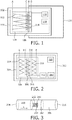
Figure 1 schematically displays a first embodiment of the system according to the invention, wherein the sensor comprises a transducer arrangement build up of two thermopiles. -
Figure 2 schematically depicts a second embodiment of the sensor according to the invention, wherein the sensor is situated in the wall of a channel. -
Figure 3 schematically displays a third embodiment of the system according to the invention, wherein an electromagnetic radiation received by a sensor receiver enables a battery for powering a heating element. -
Figure 4 schematically provides an explanation for the quantities measurable by the transducer arrangements comprised in the first embodiment and the third embodiment of the sensor according to the invention. -
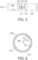
Figure 5 schematically depicts a fourth embodiment of the sensor according to the invention, wherein the sensor is situated in the wall of a channel and wherein the sensor comprises a transducer arrangement build up of three thermopiles. -
Figure 6 schematically shows a cross-sectional view of a fifth embodiment of the sensor according to the invention, wherein the sensor is aligned co-axially with the channel. -
Figure 7 schematically shows an embodiment of the system according to the invention, wherein the control unit according to the invention is arranged for cooperation with the sensor according to the invention. -
Figure 8 schematically displays a flowchart representing an embodiment of the method according to the invention wherein control unit is being reused. -
Figure 1 displays asensor 102 comprising achip 104 which has a substrate manufactured from poly-imide. The benefit of the latter materials is in their relatively low RF power loss. Here RF refers to Radio Frequency, which implies a frequency ranging from approximately 1 MHz up to about 10 GHz. Thesensor 102 further comprises anantenna 110 for receiving an electromagnetic radiation. The energy contained in the electromagnetic radiation is employed for powering aheating element 106, whichheating element 106 is arranged for heating a fluid. Theheating element 106 is integrated with theantenna 110 through locally providing a relatively large electrical resistance to theantenna 110. Theantenna 110 is locally provided with a material having a higher electrical resistance or alternatively, theantenna 110 is locally provided with a smaller cross-sectional area. Consequently, power will be dissipated along the relatively large electrical resistance, which dissipation will result in heating. Theantenna 110, at least its part which is not arranged for heating the fluid, is not situated on thechip 104. - The
chip 104 comprises atransducer arrangement 108, whichtransducer arrangement 108 comprises afirst thermopile 112 and asecond thermopile 114. In this text, a thermopile refers to a series connection of a plurality of thermocouples. A thermopile produces an output relating to a local temperature gradient or temperature difference rather than measuring an absolute temperature. Thefirst thermopile 112 registers the difference between the temperatures at line A and at line B. Hence, thefirst thermopile 112 measures the difference between the temperature of theheating element 106 and the temperature at a reference position, which temperature is further referred to as the reference temperature. Likewise, thesecond thermopile 114 measures the difference between the temperatures at line C and at line D. Therefore, thesecond thermopile 114 measures the difference between the temperature of the fluid after passing theheating element 106 and the temperature of the fluid prior to passing theheating element 106. Thetransducer arrangement 108 is arranged for generating a measurement signal indicative for a velocity of a fluid flowing through a channel based on the outputs of thefirst thermopile 112 and thesecond thermopile 114. The chip further comprises asensor transmitter 116 for transmitting the measurement signal generated by thetransducer arrangement 108. Furthermore, the chip comprises amemory 118. In thememory 118 data are stored, which data can contain the calibration qualities of the channel through which the fluid from which the velocity is to be measured by thesensor 102 is flowing. The employment of thesensor 102 in cooperation with a channel is disclosed infigure 2 , which figure relates to the second embodiment of the sensor according to the invention. -
Figure 2 displays an embodiment of the sensor according to the invention wherein thesensor 202 is situated at awall 204 of achannel 206 for measuring a velocity v [m/s] of a fluid 208 flowing through thechannel 206. Aheating element 210 is arranged for heating thefluid 208. Afirst thermopile 212 is arranged for measuring the difference between the temperature Theat [K] of theheating element 210 and a reference temperature Tref which is registered at a distance xref, seefigure 4 , downstream from theheating element 210. The output of thefirst thermopile 212, i.e. Theat - Tref , relates to the power P [W] supplied to theheating element 210 and the flow velocity v of the fluid 208 in thechannel 206 according to the following relationship:


sensor 202 to the fluid 208, h is the height of the flow channel, seefigure 4 wherein a graphical explanation is given for the aforementioned quantities. Further, bheat is the width of theheating element 210, afl is the thermal diffusivity of the fluid 208, lfl is the thermal conductivity of the fluid 208 and λwall is the thermal conductivity of thewall 204, i.e. the thermal conductivity of the material in between thesensor 202 and thefluid 208. - A
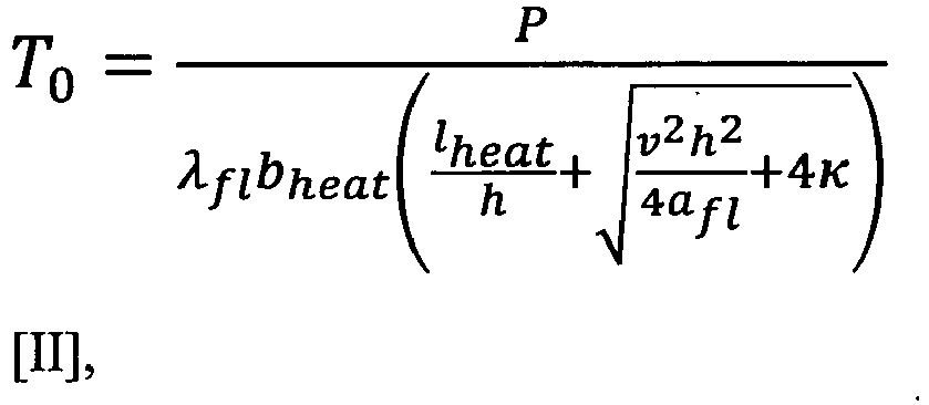
second thermopile 214 is arranged for measuring the difference between the temperature Tafter of the fluid 208 after passing theheating element 210 and the temperature Tprior [K] of the fluid 208 prior to passing theheating element 210. The output of thefirst thermopile 212, i.e. Tafter - Tprior , relates to the velocity v of the fluid 208 in thechannel 206 and the temperature T0 according to the following relationship:
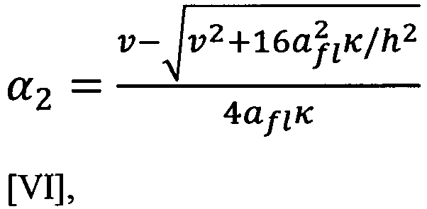
heating element 110 to the locations at which Tprior and Tafer are being registered by thesecond thermopile 214, seefigure 4 . - The measurement signal generated by the transducer arrangement (not shown) comprised in the
sensor 202 is based on the ratio τ of the output of thefirst thermopile 212 and the output of thesecond thermopile 214. Provided P ≠ 0, the measurement signal τ follows from the following dimensionless relationship:
heating element 210. Hence, the measurement signal is robust regarding disturabnces acting on the power dissipated by theheating element 210. Furthermore, the measurement signal according to relationship [V] is invariant under variations in an ambient temperature. Hence, it has no offset regarding temperature. Furthermore, the measurement signal is sensitive to a substantially large range of the velocity v of the fluid 208 flowing through thechannel 206. As a result, the measurement signal provides a relatively large range in which it is indicative for the velocity v. - The
sensor 202 is calibrated by measuring the ratio τ for a range of velocities and storing the calibration by means of a look-up table in a memory (not shown) comprised in thesensor 202. On the basis of the calibration, the velocity v can be determined during use by measuring τ and by subsequently employing the look-up table. Alternatively, the velocity v can be computed on the basis of [V] by measuring the ratio τ and by subsequently employing an iterative scheme, e.g. the Newton-Raphson method or the bisection method, which imply the computation of v for which the equation τ - (e α2 xafter - e -α1 xprior )/(1 - e -α1 xref ) equals zero. An advantage of the latter approach is in the fact that modifications in e.g. fluid properties can be accounted for. - In equations [I] to [V], the velocity v is presumed to have a uniform profile across a
cross-sectional area 216 of theflow channel 206. However, for a laminar flow regime a parabolic velocity profile will be obtained. Within a relatively large range of flow velocities, the uniform velocity profile can be unambiguously related to the parabolic velocity profile. Therefore, the discrepancy mentioned before imposes no limitation regarding the accuracy of thesensor 202. -
Figure 3 displays asensor 302 comprising achip 304 which has a substrate manufactured from poly-imides, and asensor receiver 310. Thesensor receiver 310 is arranged for receiving an electromagnetic radiation. Thechip 304 comprises aheating element 306 and atransducer arrangement 308. Here, an energy contained in the electromagnetic radiation is employed for enabling a preferably miniaturizedbattery 312. The energy stored in thebattery 312 is employed for powering theheating element 306. Thetransducer arrangement 308 comprises afirst thermopile 314, asecond thermopile 316 and athird thermopile 318. - The
first thermopile 314 registers the numerical difference between the temperatures at line A and at line B. Hence, thefirst thermopile 314 measures the difference between the temperatures of the fluid at two locations prior to theheating element 306. Likewise, thesecond thermopile 114 measures the difference between the temperatures at line C and at line D. Therefore, thesecond thermopile 114 measures the difference between the temperature of the fluid after passing theheating element 106 and the temperature of the fluid prior to passing theheating element 106. Thethird thermopile 318 registers the numerical difference between the temperatures at line E and at line F. Hence, thethird thermopile 318 measures the difference between the temperatures of the fluid at two locations after theheating element 306. Thetransducer arrangement 308 is arranged for generating a measurement signal indicative for a velocity of a fluid flowing through a channel based on the outputs of thefirst thermopile 314, thesecond thermopile 316 and thethird thermopile 318. Thechip 304 further comprises asensor transmitter 320 for transmitting the measurement signal generated by thetransducer arrangement 308. The employment of thesensor 302 in cooperation with a channel through which the fluid from which the velocity is to be measured by thesensor 302 is flowing is disclosed infigure 5 , which figure relates to the fourth embodiment of the sensor according to the invention. -
Figure 5 displays an embodiment of the sensor according to the invention wherein thesensor 502 is situated at awall 504 of achannel 506 for measuring a velocity v [m/s] of a fluid 508 flowing through thechannel 506. Aheating element 510 is arranged for heating thefluid 508. - A
first thermopile 512 is arranged for measuring the difference between the temperatures Tprior' [K] and Tprior" [K] of the fluid 508 at two locations downstream of theheating element 510. The output of thefirst thermopile 512, i.e. Tprior' - T prior", relates to the velocity v of the fluid 508 in thechannel 506 and the temperature To according to the following relationship:
- A
second thermopile 514 is arranged for measuring the difference between the temperature Tafter of the fluid 508 after passing theheating element 510 and the temperature Tprior [K] of the fluid 508 prior to passing theheating element 210. The output of thesecond thermopile 514, i.e. Tafter - Tprior , relates to the velocity v of the fluid 208 in thechannel 206 and the temperature To according to equation [V]. - A
third thermopile 516 is arranged for measuring the difference between the temperatures Tafter' [K] and Tafter" [K] of the fluid 508 at two locations upstream of theheating element 510. The output of thethird thermopile 516, i.e. Tafter' - Tafter" , relates to the velocity v of the fluid 508 in thechannel 506 and the temperature T0 according to the following relationship:
- The measurement signal generated by the transducer arrangement (not shown) comprised in the
sensor 502 is based on the ratio τ' of the outputs of thefirst thermopile 512, thesecond thermopile 514 and thethird thermopile 516. Provided P ≠ 0, the measurement signal τ' follows from the following dimensionless relationship:
heating element 510. Hence, the measurement signal is robust regarding disturabnc4s acting on the power dissipated by theheating element 510. Furthermore, the measurement signal according to relationship [V] is invariant under variations in an ambient temperature. Hence, it has no offset regarding temperature. Furthermore, the measurement signal is sensitive to a substantially large range of the velocity v of the fluid 508 flowing through thechannel 506. As a result, the measurement signal provides a relatively large range in which it is indicative for the velocity v. -
Figure 6 displays a preferred embodiment wherein thesensor 602 is situated in awall 604 of thechannel 606, for measuring a velocity of the fluid 608 flowing through thechannel 606. Thewall 604 of thechannel 606 is made of a suitable plastic such as poly-imide. Thechannel 606 has an inner radius R1 and an outer radius R2 . Thesensor 602 is arranged co-axially with thechannel 606 at a radius R3 for which it holds that R1 < R2 ≤ R3. Preferably, to reduce the thermal resistance between the fluid and the flow sensor with the purpose of increasing the level of accuracy for the measurement signal generated by the transducer arrangement (not shown) comprised in thesensor 602, the distance R2 - R1 is relatively small, e.g. at about 60 µm. Clearly, thesensor 602 does not physically contact the fluid 608 flowing through thechannel 606. Preferably, thesensor 602 envelops the fluid 608 to a relatively large extend in order to increase an accuracy of a measurement signal generated by a transducer arrangement (not shown) comprised in thesensor 602. -
Figure 7 displays an embodiment of the system according to the invention. The system comprises acontrol unit 702 and asensor 704. The sensor is situated in awall 706 of achannel 708. Thecontrol unit 702 is arranged for cooperation with thesensor 704. Thecontrol unit 702 comprises afirst body 710 and asecond body 712. In this embodiment, both bodies are elongated bodies. In this embodiment, thefirst body 710 and thesecond body 712 are connected via ahinge arrangement 714. Hence, thefirst body 710, thesecond body 714 and the hinge arrangement constitute a casing. Alternatively, the first and the second body may be connectable by means of screws, snap fasteners or clamps. - The
hinge arrangement 714 establishes a mutual rotational degree of freedom ϕ along an axis ofrotation 716 for thefirst body 710 and thesecond body 712. Thefirst body 710 comprises afirst face 717 having afirst cavity 718 whereas the second body comprises asecond face 719 having asecond cavity 720. In case the mutual rotational degree of freedom ϕ vanishes, i.e. thefaces first cavity 718 and thesecond cavity 720 is capable of encasing thechannel 708. - The
control unit 702 comprises acontrol transmitter 722 for transmitting an electromagnetic radiation to the sensor receiver (not shown) comprised in thesensor 704 for powering the heating element (not shown) comprised in thesensor 704. Herein, the heating element is powered via an energy contained in the electromagnetic radiation itself. Alternatively, the electromagnetic radiation can be employed to enable the energy storage such as a miniaturized battery (not shown) comprised in the sensor, which miniaturized battery powers the heating element in its turn. - The
control unit 702 furthermore comprises acontrol actuator 724 for controlling the flow velocity of the fluid 726 flowing through thechannel 708. Consequently, a dependence of the flow velocity on external circumstances such as gravity is prevented from. Theactuator 724 is implemented by a preferablycylindrical body 728 which is eccentrically rotatable around apivot 730 by anelectromagnetic motor 732. Theelectromagnetic motor 732 is controllable by a signal relating to a deviation between the predefined flow velocity of the fluid 726 in thechannel 708 and the velocity indicated by a measurement signal generated by a transducer arrangement (not shown) in thesensor 704. Hence no intervention of e.g. a doctor or a paramedic is required to adjust a setting of theactuator 724 in order to bring the velocity of the fluid 726 in thechannel 708 in conformity with a predefined medication regime. Theactuator 724 comprises anactuator receiver 734 for receiving the measurement signal generated by the transducer arrangement comprised in thesensor 704. Acomparator 736 compares the measurement signal received by theactuator receiver 734 to a predefined reference value for the velocity of the fluid 726 in thechannel 708, which reference value is grounded on a predetermined medication regime. - By appropriately encasing the
channel 708 through vanishing of the rotational degree of freedom ϕ along the axis ofmutual rotation 716, the eccentricallyrotatable body 718 contained in theactuator 724 is able to control a size of a cross-section of thechannel 708. With that, the flow velocity v of the fluid 726 in thechannel 708 is effectively controlled. - The
first cavity 718 comprises a first plurality ofcircular hollows 738. The first plurality ofcircular hollows 738 has a non-parallel orientation compared to thefirst cavity 718. Likewise, thesecond cavity 720 comprises a second plurality ofcircular hollows 740. The second plurality ofcircular hollows 740 has an orientation matching to the orientation of the first plurality ofcircular hollows 738. The first plurality ofcircular hollows 738 and the second plurality ofcircular hollows 740 are arranged for encasing a plurality ofbulges 742 mounted on thechannel 708. By appropriately encasing thechannel 708 through vanishing of the rotational degree of freedom ϕ along the axis ofmutual rotation 716, and by aligning the plurality ofbulges 742 with the first plurality ofcircular hollows 738 and the second plurality ofcircular hollows 740, a mutual axial position of thechannel 708 and thecontrol unit 702 is established. - The system comprising the
control unit 702 and thesensor 704 may be integrated into a system that stores, displays and analyzes information regarding the velocity of the fluid 726 flowing through thechannel 708. - An example of such a system may be a patient monitoring system. In a patient monitoring system, several devices measure vital signs such as a patient's bloodpressure and heartrate and transmit them to a monitoring device. The monitoring device stores information regarding the vital signs and analyses and displays this information, for instance upon request by a medical professional. The information provided by the
sensor 704 regarding the velocity of the fluid 726 flowing through thechannel 708 may be essential to be monitored by the patient monitoring system, e.g. in applications such as intravenous infusion. For this purpose, the control unit is employed with a further control transmitter 744, which preferably provides a wireless connection to the patient monitoring system. - It is stressed the application of the
sensor 704 allows for application in conjunction with a range of pumps, medical gravity drips or disposable pump systems, possibly manufactured by various companies. Because of that, thesensor 704 can act as a standard interface between fluid transportation systems and the patient monitoring system aforementioned. -
Figure 8 displays a flowchart representing an embodiment of the method according to the invention. The method is arranged for delivery of a liquid medication, particularly intravenous delivery of a liquid medication under sterile conditions. Astep 802 comprises establishing a predefined value for the velocity v based on a specific therapeutic regime. Astep 804 comprises detachably connecting the control unit in conformity with the embodiment of the system according to the invention to a channel, which channel contains in its wall the sensor pursuant to the first embodiment of the sensor according to the invention. Astep 806 comprises controlled delivery of a liquid medication by controlling the control actuator comprised in the control unit on the basis of a signal relating to a deviation between the predefined level for the velocity and a velocity indicated by a measurement signal generated by a transducer arrangement comprised in the sensor. Astep 808 comprises disconnecting the control unit from the channel. The step of establishing a predefined value for the velocity v can be carried out multiple times, i.e. for instance during the delivery of the fluid. - While the invention has been illustrated and described in detail in the drawings and in the foregoing description, the illustrations and the description are to be considered illustrative or exemplary and not restrictive. The invention is not limited to the disclosed embodiments. It is noted that the sensor and the control unit according to the invention and all its components can be made by applying processes and materials known per se. In the set of claims and the description the word "comprising" does not exclude other elements and the indefinite article "a" or "an" does not exclude a plurality. Any reference signs in the claims should not be construed as limiting the scope. It is further noted that all possible combinations of features as defined in the set of claims are part of the invention.
Claims (12)
- A sensor (102) for measuring a velocity of a fluid (208) flowing through a channel (206), which sensor comprises a chip (104) and a sensor receiver (310), which chip comprises a heating element (106) for heating the fluid, and a transducer arrangement (108) for generating a measurement signal indicative for the velocity of the fluid flowing through the channel based on a ratio of spatial temperature differences,
characterized in that the sensor receiver is arranged for receiving an electromagnetic radiation for powering the heating element, and in that the sensor receiver is an antenna (110), in which antenna the heating element is integrated. - The sensor according to claim 1, wherein the transducer arrangement is arranged for generating the measurement signal based on the ratio of a first spatial temperature difference and a second spatial temperature difference, the first spatial temperature difference being the numerical difference between the temperature of the fluid prior to the heating element and the temperature of the fluid after the heating element, and the second spatial temperature difference being the numerical difference between temperatures of the fluid at locations prior to the heating element added to the numerical difference between temperatures of the fluid at locations after the heating element.
- The sensor according to claim 1, wherein the heating element (106) is integrated with the antenna (110) through locally providing a relatively large electrical resistance to the antenna (110).
- The sensor according to claim 1, wherein the chip comprises a sensor transmitter (116) for transmitting the measurement signal.
- The sensor according to claim 1, wherein the chip comprises a memory (118) for storing calibration data of the channel.
- A control unit (702) arranged for cooperation with the sensor according to claim 1, characterized in that the control unit comprises a control transmitter (722) for transmitting the electromagnetic radiation to the sensor receiver, and the control transmitter is arranged for powering the heating element via an energy contained in the electromagnetic radiation, wherein the control unit further comprises a facility for detachably connecting the control unit to the channel.
- The control unit according to claim 6, wherein the control unit comprises a control actuator (724) for controlling the flow velocity of the fluid flowing through the channel.
- The control unit according to claim 7, wherein the control unit comprises means for controlling the control actuator by a signal relating to a deviation between a predefined flow velocity and the velocity indicated by the measurement signal generated by the transducer arrangement comprised in the sensor according to claim 1.
- The control unit according to claim 8, wherein the actuator comprises an actuator receiver (734) for receiving the measurement signal generated by the transducer arrangement comprised in the sensor according to claim 1.
- A system comprising the sensor according to claim 1 and the control unit according to claim 6.
- Use of the system according to claim 10 in a medical application.
- A method for controlled delivery of a liquid medication, comprising a step (802) of establishing a predefined fluid flow velocity, a step (804) of detachably connecting the control unit according to claim 7 to a channel, a step (806) of controlled delivery of the liquid medication through the channel by controlling the sensor according to claim 1 and the actuator according to claim 7.
Priority Applications (1)
| Application Number | Priority Date | Filing Date | Title |
|---|---|---|---|
| EP09786497.9A EP2300787B1 (en) | 2008-07-08 | 2009-07-02 | Sensor and control unit for flow control and a method for controlled delivery of fluid |
Applications Claiming Priority (3)
| Application Number | Priority Date | Filing Date | Title |
|---|---|---|---|
| EP08159864 | 2008-07-08 | ||
| EP09786497.9A EP2300787B1 (en) | 2008-07-08 | 2009-07-02 | Sensor and control unit for flow control and a method for controlled delivery of fluid |
| PCT/IB2009/052874 WO2010004484A1 (en) | 2008-07-08 | 2009-07-02 | Sensor and control unit for flow control and a method for controlled delivery of fluid |
Publications (2)
| Publication Number | Publication Date |
|---|---|
| EP2300787A1 EP2300787A1 (en) | 2011-03-30 |
| EP2300787B1 true EP2300787B1 (en) | 2017-03-29 |
Family
ID=40084493
Family Applications (1)
| Application Number | Title | Priority Date | Filing Date |
|---|---|---|---|
| EP09786497.9A Not-in-force EP2300787B1 (en) | 2008-07-08 | 2009-07-02 | Sensor and control unit for flow control and a method for controlled delivery of fluid |
Country Status (6)
| Country | Link |
|---|---|
| US (1) | US8784367B2 (en) |
| EP (1) | EP2300787B1 (en) |
| JP (1) | JP5558463B2 (en) |
| CN (1) | CN102089632A (en) |
| RU (1) | RU2509984C2 (en) |
| WO (1) | WO2010004484A1 (en) |
Families Citing this family (15)
| Publication number | Priority date | Publication date | Assignee | Title |
|---|---|---|---|---|
| CN102089680B (en) * | 2008-07-10 | 2016-08-17 | 皇家飞利浦电子股份有限公司 | Optical image probe |
| US8794081B2 (en) * | 2009-03-05 | 2014-08-05 | Koninklijke Philips N.V. | Sensor for detecting bubbles in a liquid flowing through a flow path |
| JP5848700B2 (en) * | 2009-05-28 | 2016-01-27 | コーニンクレッカ フィリップス エヌ ヴェKoninklijke Philips N.V. | Device for monitoring the position of the distal end of a tube relative to a blood vessel |
| CN102599900A (en) * | 2012-03-30 | 2012-07-25 | 上海应用技术学院 | Fluid pressure measuring sac tube |
| DE102012219304A1 (en) | 2012-10-23 | 2014-04-24 | Continental Automotive Gmbh | Air flow sensor |
| JP6225766B2 (en) * | 2014-03-13 | 2017-11-08 | オムロン株式会社 | Internal temperature measurement method and internal temperature measurement device |
| US10670554B2 (en) * | 2015-07-13 | 2020-06-02 | International Business Machines Corporation | Reconfigurable gas sensor architecture with a high sensitivity at low temperatures |
| CN107708788A (en) * | 2015-09-14 | 2018-02-16 | 泰尔茂株式会社 | Liquid device is administered |
| KR102516080B1 (en) * | 2020-09-14 | 2023-03-31 | 한국표준과학연구원 | Thermal mass flow meter |
| DE102021200496A1 (en) * | 2021-01-20 | 2022-07-21 | Raumedic Ag | Medical flow sensor module assembly |
| DE102021212234A1 (en) * | 2021-10-29 | 2023-05-04 | New Ventures GmbH | Sensor assembly for an organ transport system |
| WO2023094034A1 (en) * | 2021-11-28 | 2023-06-01 | Nvention Ltd | Flow sensing device and method |
| JP2025514941A (en) | 2022-04-19 | 2025-05-13 | アムシノ メディカル インコーポレーテッド | Flow sensor system and method of use thereof |
| CN115200659A (en) * | 2022-07-13 | 2022-10-18 | 北京航空航天大学 | Small gas flow measuring device and measuring method thereof |
| CN119610644B (en) * | 2024-12-25 | 2025-10-03 | 哈尔滨工业大学 | A high-precision circuit additive manufacturing method based on aerosol printing |
Family Cites Families (21)
| Publication number | Priority date | Publication date | Assignee | Title |
|---|---|---|---|---|
| US5233868A (en) * | 1992-04-13 | 1993-08-10 | Coats Montgomery R | Non-intrusive mass flow measuring apparatus and method |
| JP2621740B2 (en) * | 1992-05-28 | 1997-06-18 | インター・ノバ株式会社 | Medical catheter flow meter |
| WO1995002164A1 (en) | 1993-07-07 | 1995-01-19 | Ic Sensors, Inc. | Pulsed thermal flow sensor system |
| US5569187A (en) * | 1994-08-16 | 1996-10-29 | Texas Instruments Incorporated | Method and apparatus for wireless chemical supplying |
| US5704352A (en) * | 1995-11-22 | 1998-01-06 | Tremblay; Gerald F. | Implantable passive bio-sensor |
| RU2106639C1 (en) * | 1996-04-19 | 1998-03-10 | Институт проблем управления РАН | Method measuring velocity of stream and device for its implementation |
| EP1065475B1 (en) * | 1999-05-31 | 2017-07-12 | Sensirion Holding AG | Method of measuring a gas flow |
| US6208254B1 (en) * | 1999-09-15 | 2001-03-27 | Fluid Components Intl | Thermal dispersion mass flow rate and liquid level switch/transmitter |
| CH695166A5 (en) * | 2000-04-25 | 2005-12-30 | Sensirion Ag | Method and apparatus for measuring the flow of a liquid. |
| US6589229B1 (en) * | 2000-07-31 | 2003-07-08 | Becton, Dickinson And Company | Wearable, self-contained drug infusion device |
| US6685668B1 (en) * | 2000-07-31 | 2004-02-03 | Abbott Laboratories | Closed-loop IV fluid flow control |
| WO2003071384A2 (en) | 2002-02-15 | 2003-08-28 | Eunoe, Inc. | Systems and methods for flow detection and measurement in csf shunts |
| US20030236489A1 (en) * | 2002-06-21 | 2003-12-25 | Baxter International, Inc. | Method and apparatus for closed-loop flow control system |
| MXPA05011377A (en) * | 2003-04-23 | 2006-01-30 | Vasogen Ireland Ltd | Dispensing systems. |
| US20040215067A1 (en) * | 2003-04-24 | 2004-10-28 | Stiger Mark L. | Flow sensor device for endoscopic third ventriculostomy |
| US6813964B1 (en) * | 2003-05-21 | 2004-11-09 | Hospira, Inc. | Fluid flow measurement device |
| US7361155B2 (en) * | 2003-09-16 | 2008-04-22 | Therafuse, Inc. | Compensating liquid delivery system and method |
| US7096729B2 (en) * | 2004-06-08 | 2006-08-29 | Honeywell International Inc. | Disposable fluid flow sensor |
| US20050277839A1 (en) * | 2004-06-10 | 2005-12-15 | Honeywell International, Inc. | Wireless flow measurement in arterial stent |
| BRPI0622094A2 (en) * | 2005-04-06 | 2011-07-12 | Mallinckrodt Inc | systems and methods for managing medical fluid information and containers |
| DE602006019548D1 (en) * | 2006-03-31 | 2011-02-24 | Sensirion Holding Ag | Flow sensor with thermocouples |
-
2009
- 2009-07-02 WO PCT/IB2009/052874 patent/WO2010004484A1/en not_active Ceased
- 2009-07-02 EP EP09786497.9A patent/EP2300787B1/en not_active Not-in-force
- 2009-07-02 CN CN2009801264343A patent/CN102089632A/en active Pending
- 2009-07-02 US US13/001,798 patent/US8784367B2/en active Active
- 2009-07-02 JP JP2011517286A patent/JP5558463B2/en not_active Expired - Fee Related
- 2009-07-02 RU RU2011104373/28A patent/RU2509984C2/en active
Non-Patent Citations (1)
| Title |
|---|
| None * |
Also Published As
| Publication number | Publication date |
|---|---|
| EP2300787A1 (en) | 2011-03-30 |
| US8784367B2 (en) | 2014-07-22 |
| WO2010004484A1 (en) | 2010-01-14 |
| RU2509984C2 (en) | 2014-03-20 |
| RU2011104373A (en) | 2012-08-20 |
| CN102089632A (en) | 2011-06-08 |
| US20110118705A1 (en) | 2011-05-19 |
| JP5558463B2 (en) | 2014-07-23 |
| JP2011527749A (en) | 2011-11-04 |
Similar Documents
| Publication | Publication Date | Title |
|---|---|---|
| US8784367B2 (en) | Sensor and control unit for flow control and a method for controlled delivery of fluid | |
| EP2403558B1 (en) | Sensor for detecting bubbles in a liquid flowing through a flow path | |
| US10668226B2 (en) | System and method for measuring delivered dose | |
| EP2120817B1 (en) | Device for heating a flow of liquid by electrical heating of a metallic conduit | |
| EP2434946B1 (en) | Apparatus for monitoring a position of a tube's distal end with respect to a blood vessel | |
| EP2724124B1 (en) | Method and apparatus for measuring the flow rate of a liquid | |
| US9642966B2 (en) | Intravenous (IV) infusion monitoring method and system | |
| Salmaz et al. | High-precision capacitive sensors for intravenous fluid monitoring in hospitals | |
| US7908931B1 (en) | Non invasive flow rate measuring system and method | |
| US20240044684A1 (en) | Device for measuring rate of body fluid flow through a tube | |
| NL2037975B1 (en) | Microflow sensor | |
| CN117771474A (en) | Flexible non-contact flow detection sensing device and infusion monitoring system | |
| WO2025085887A1 (en) | Device for measuring rate of body fluid flow through a tube | |
| Tamura et al. | A zero-heat-flow transducer for monitoring perfusion blood temperature | |
| EP2914315A1 (en) | Intravenous (iv) infusion monitoring method and system | |
| WO2014070112A1 (en) | Intravenous (iv) infusion monitoring method and system |
Legal Events
| Date | Code | Title | Description |
|---|---|---|---|
| PUAI | Public reference made under article 153(3) epc to a published international application that has entered the european phase |
Free format text: ORIGINAL CODE: 0009012 |
|
| 17P | Request for examination filed |
Effective date: 20110208 |
|
| AK | Designated contracting states |
Kind code of ref document: A1 Designated state(s): AT BE BG CH CY CZ DE DK EE ES FI FR GB GR HR HU IE IS IT LI LT LU LV MC MK MT NL NO PL PT RO SE SI SK SM TR |
|
| AX | Request for extension of the european patent |
Extension state: AL BA RS |
|
| DAX | Request for extension of the european patent (deleted) | ||
| RAP1 | Party data changed (applicant data changed or rights of an application transferred) |
Owner name: KONINKLIJKE PHILIPS N.V. |
|
| GRAP | Despatch of communication of intention to grant a patent |
Free format text: ORIGINAL CODE: EPIDOSNIGR1 |
|
| INTG | Intention to grant announced |
Effective date: 20160704 |
|
| GRAJ | Information related to disapproval of communication of intention to grant by the applicant or resumption of examination proceedings by the epo deleted |
Free format text: ORIGINAL CODE: EPIDOSDIGR1 |
|
| GRAJ | Information related to disapproval of communication of intention to grant by the applicant or resumption of examination proceedings by the epo deleted |
Free format text: ORIGINAL CODE: EPIDOSDIGR1 |
|
| GRAP | Despatch of communication of intention to grant a patent |
Free format text: ORIGINAL CODE: EPIDOSNIGR1 |
|
| INTC | Intention to grant announced (deleted) | ||
| INTG | Intention to grant announced |
Effective date: 20161019 |
|
| GRAS | Grant fee paid |
Free format text: ORIGINAL CODE: EPIDOSNIGR3 |
|
| GRAA | (expected) grant |
Free format text: ORIGINAL CODE: 0009210 |
|
| AK | Designated contracting states |
Kind code of ref document: B1 Designated state(s): AT BE BG CH CY CZ DE DK EE ES FI FR GB GR HR HU IE IS IT LI LT LU LV MC MK MT NL NO PL PT RO SE SI SK SM TR |
|
| REG | Reference to a national code |
Ref country code: GB Ref legal event code: FG4D |
|
| REG | Reference to a national code |
Ref country code: CH Ref legal event code: EP |
|
| REG | Reference to a national code |
Ref country code: AT Ref legal event code: REF Ref document number: 880212 Country of ref document: AT Kind code of ref document: T Effective date: 20170415 |
|
| REG | Reference to a national code |
Ref country code: IE Ref legal event code: FG4D |
|
| REG | Reference to a national code |
Ref country code: DE Ref legal event code: R096 Ref document number: 602009045104 Country of ref document: DE |
|
| REG | Reference to a national code |
Ref country code: FR Ref legal event code: PLFP Year of fee payment: 9 |
|
| PG25 | Lapsed in a contracting state [announced via postgrant information from national office to epo] |
Ref country code: GR Free format text: LAPSE BECAUSE OF FAILURE TO SUBMIT A TRANSLATION OF THE DESCRIPTION OR TO PAY THE FEE WITHIN THE PRESCRIBED TIME-LIMIT Effective date: 20170630 Ref country code: NO Free format text: LAPSE BECAUSE OF FAILURE TO SUBMIT A TRANSLATION OF THE DESCRIPTION OR TO PAY THE FEE WITHIN THE PRESCRIBED TIME-LIMIT Effective date: 20170629 Ref country code: LT Free format text: LAPSE BECAUSE OF FAILURE TO SUBMIT A TRANSLATION OF THE DESCRIPTION OR TO PAY THE FEE WITHIN THE PRESCRIBED TIME-LIMIT Effective date: 20170329 Ref country code: HR Free format text: LAPSE BECAUSE OF FAILURE TO SUBMIT A TRANSLATION OF THE DESCRIPTION OR TO PAY THE FEE WITHIN THE PRESCRIBED TIME-LIMIT Effective date: 20170329 Ref country code: FI Free format text: LAPSE BECAUSE OF FAILURE TO SUBMIT A TRANSLATION OF THE DESCRIPTION OR TO PAY THE FEE WITHIN THE PRESCRIBED TIME-LIMIT Effective date: 20170329 |
|
| REG | Reference to a national code |
Ref country code: NL Ref legal event code: MP Effective date: 20170329 |
|
| REG | Reference to a national code |
Ref country code: AT Ref legal event code: MK05 Ref document number: 880212 Country of ref document: AT Kind code of ref document: T Effective date: 20170329 |
|
| PG25 | Lapsed in a contracting state [announced via postgrant information from national office to epo] |
Ref country code: SE Free format text: LAPSE BECAUSE OF FAILURE TO SUBMIT A TRANSLATION OF THE DESCRIPTION OR TO PAY THE FEE WITHIN THE PRESCRIBED TIME-LIMIT Effective date: 20170329 Ref country code: BG Free format text: LAPSE BECAUSE OF FAILURE TO SUBMIT A TRANSLATION OF THE DESCRIPTION OR TO PAY THE FEE WITHIN THE PRESCRIBED TIME-LIMIT Effective date: 20170629 Ref country code: LV Free format text: LAPSE BECAUSE OF FAILURE TO SUBMIT A TRANSLATION OF THE DESCRIPTION OR TO PAY THE FEE WITHIN THE PRESCRIBED TIME-LIMIT Effective date: 20170329 |
|
| PG25 | Lapsed in a contracting state [announced via postgrant information from national office to epo] |
Ref country code: NL Free format text: LAPSE BECAUSE OF FAILURE TO SUBMIT A TRANSLATION OF THE DESCRIPTION OR TO PAY THE FEE WITHIN THE PRESCRIBED TIME-LIMIT Effective date: 20170329 |
|
| PG25 | Lapsed in a contracting state [announced via postgrant information from national office to epo] |
Ref country code: SK Free format text: LAPSE BECAUSE OF FAILURE TO SUBMIT A TRANSLATION OF THE DESCRIPTION OR TO PAY THE FEE WITHIN THE PRESCRIBED TIME-LIMIT Effective date: 20170329 Ref country code: ES Free format text: LAPSE BECAUSE OF FAILURE TO SUBMIT A TRANSLATION OF THE DESCRIPTION OR TO PAY THE FEE WITHIN THE PRESCRIBED TIME-LIMIT Effective date: 20170329 Ref country code: IT Free format text: LAPSE BECAUSE OF FAILURE TO SUBMIT A TRANSLATION OF THE DESCRIPTION OR TO PAY THE FEE WITHIN THE PRESCRIBED TIME-LIMIT Effective date: 20170329 Ref country code: EE Free format text: LAPSE BECAUSE OF FAILURE TO SUBMIT A TRANSLATION OF THE DESCRIPTION OR TO PAY THE FEE WITHIN THE PRESCRIBED TIME-LIMIT Effective date: 20170329 Ref country code: RO Free format text: LAPSE BECAUSE OF FAILURE TO SUBMIT A TRANSLATION OF THE DESCRIPTION OR TO PAY THE FEE WITHIN THE PRESCRIBED TIME-LIMIT Effective date: 20170329 Ref country code: AT Free format text: LAPSE BECAUSE OF FAILURE TO SUBMIT A TRANSLATION OF THE DESCRIPTION OR TO PAY THE FEE WITHIN THE PRESCRIBED TIME-LIMIT Effective date: 20170329 Ref country code: CZ Free format text: LAPSE BECAUSE OF FAILURE TO SUBMIT A TRANSLATION OF THE DESCRIPTION OR TO PAY THE FEE WITHIN THE PRESCRIBED TIME-LIMIT Effective date: 20170329 |
|
| PG25 | Lapsed in a contracting state [announced via postgrant information from national office to epo] |
Ref country code: IS Free format text: LAPSE BECAUSE OF FAILURE TO SUBMIT A TRANSLATION OF THE DESCRIPTION OR TO PAY THE FEE WITHIN THE PRESCRIBED TIME-LIMIT Effective date: 20170729 Ref country code: PT Free format text: LAPSE BECAUSE OF FAILURE TO SUBMIT A TRANSLATION OF THE DESCRIPTION OR TO PAY THE FEE WITHIN THE PRESCRIBED TIME-LIMIT Effective date: 20170731 Ref country code: PL Free format text: LAPSE BECAUSE OF FAILURE TO SUBMIT A TRANSLATION OF THE DESCRIPTION OR TO PAY THE FEE WITHIN THE PRESCRIBED TIME-LIMIT Effective date: 20170329 Ref country code: SM Free format text: LAPSE BECAUSE OF FAILURE TO SUBMIT A TRANSLATION OF THE DESCRIPTION OR TO PAY THE FEE WITHIN THE PRESCRIBED TIME-LIMIT Effective date: 20170329 |
|
| REG | Reference to a national code |
Ref country code: DE Ref legal event code: R097 Ref document number: 602009045104 Country of ref document: DE |
|
| PG25 | Lapsed in a contracting state [announced via postgrant information from national office to epo] |
Ref country code: DK Free format text: LAPSE BECAUSE OF FAILURE TO SUBMIT A TRANSLATION OF THE DESCRIPTION OR TO PAY THE FEE WITHIN THE PRESCRIBED TIME-LIMIT Effective date: 20170329 |
|
| PLBE | No opposition filed within time limit |
Free format text: ORIGINAL CODE: 0009261 |
|
| STAA | Information on the status of an ep patent application or granted ep patent |
Free format text: STATUS: NO OPPOSITION FILED WITHIN TIME LIMIT |
|
| REG | Reference to a national code |
Ref country code: CH Ref legal event code: PL |
|
| 26N | No opposition filed |
Effective date: 20180103 |
|
| REG | Reference to a national code |
Ref country code: IE Ref legal event code: MM4A |
|
| PG25 | Lapsed in a contracting state [announced via postgrant information from national office to epo] |
Ref country code: LI Free format text: LAPSE BECAUSE OF NON-PAYMENT OF DUE FEES Effective date: 20170731 Ref country code: IE Free format text: LAPSE BECAUSE OF NON-PAYMENT OF DUE FEES Effective date: 20170702 Ref country code: CH Free format text: LAPSE BECAUSE OF NON-PAYMENT OF DUE FEES Effective date: 20170731 |
|
| REG | Reference to a national code |
Ref country code: BE Ref legal event code: MM Effective date: 20170731 |
|
| PG25 | Lapsed in a contracting state [announced via postgrant information from national office to epo] |
Ref country code: SI Free format text: LAPSE BECAUSE OF FAILURE TO SUBMIT A TRANSLATION OF THE DESCRIPTION OR TO PAY THE FEE WITHIN THE PRESCRIBED TIME-LIMIT Effective date: 20170329 |
|
| PG25 | Lapsed in a contracting state [announced via postgrant information from national office to epo] |
Ref country code: LU Free format text: LAPSE BECAUSE OF NON-PAYMENT OF DUE FEES Effective date: 20170702 |
|
| REG | Reference to a national code |
Ref country code: FR Ref legal event code: PLFP Year of fee payment: 10 |
|
| PG25 | Lapsed in a contracting state [announced via postgrant information from national office to epo] |
Ref country code: BE Free format text: LAPSE BECAUSE OF NON-PAYMENT OF DUE FEES Effective date: 20170731 |
|
| PG25 | Lapsed in a contracting state [announced via postgrant information from national office to epo] |
Ref country code: MT Free format text: LAPSE BECAUSE OF NON-PAYMENT OF DUE FEES Effective date: 20170702 |
|
| PG25 | Lapsed in a contracting state [announced via postgrant information from national office to epo] |
Ref country code: HU Free format text: LAPSE BECAUSE OF FAILURE TO SUBMIT A TRANSLATION OF THE DESCRIPTION OR TO PAY THE FEE WITHIN THE PRESCRIBED TIME-LIMIT; INVALID AB INITIO Effective date: 20090702 Ref country code: MC Free format text: LAPSE BECAUSE OF FAILURE TO SUBMIT A TRANSLATION OF THE DESCRIPTION OR TO PAY THE FEE WITHIN THE PRESCRIBED TIME-LIMIT Effective date: 20170329 |
|
| PG25 | Lapsed in a contracting state [announced via postgrant information from national office to epo] |
Ref country code: CY Free format text: LAPSE BECAUSE OF NON-PAYMENT OF DUE FEES Effective date: 20170329 |
|
| PG25 | Lapsed in a contracting state [announced via postgrant information from national office to epo] |
Ref country code: MK Free format text: LAPSE BECAUSE OF FAILURE TO SUBMIT A TRANSLATION OF THE DESCRIPTION OR TO PAY THE FEE WITHIN THE PRESCRIBED TIME-LIMIT Effective date: 20170329 |
|
| PG25 | Lapsed in a contracting state [announced via postgrant information from national office to epo] |
Ref country code: TR Free format text: LAPSE BECAUSE OF FAILURE TO SUBMIT A TRANSLATION OF THE DESCRIPTION OR TO PAY THE FEE WITHIN THE PRESCRIBED TIME-LIMIT Effective date: 20170329 |
|
| PGFP | Annual fee paid to national office [announced via postgrant information from national office to epo] |
Ref country code: GB Payment date: 20220719 Year of fee payment: 14 Ref country code: DE Payment date: 20220628 Year of fee payment: 14 |
|
| PGFP | Annual fee paid to national office [announced via postgrant information from national office to epo] |
Ref country code: FR Payment date: 20220725 Year of fee payment: 14 |
|
| REG | Reference to a national code |
Ref country code: DE Ref legal event code: R119 Ref document number: 602009045104 Country of ref document: DE |
|
| GBPC | Gb: european patent ceased through non-payment of renewal fee |
Effective date: 20230702 |
|
| PG25 | Lapsed in a contracting state [announced via postgrant information from national office to epo] |
Ref country code: DE Free format text: LAPSE BECAUSE OF NON-PAYMENT OF DUE FEES Effective date: 20240201 Ref country code: GB Free format text: LAPSE BECAUSE OF NON-PAYMENT OF DUE FEES Effective date: 20230702 |
|
| PG25 | Lapsed in a contracting state [announced via postgrant information from national office to epo] |
Ref country code: FR Free format text: LAPSE BECAUSE OF NON-PAYMENT OF DUE FEES Effective date: 20230731 |