EP2299962B1 - External walking assist device for those with lower leg injuries - Google Patents
External walking assist device for those with lower leg injuries Download PDFInfo
- Publication number
- EP2299962B1 EP2299962B1 EP09763674.0A EP09763674A EP2299962B1 EP 2299962 B1 EP2299962 B1 EP 2299962B1 EP 09763674 A EP09763674 A EP 09763674A EP 2299962 B1 EP2299962 B1 EP 2299962B1
- Authority
- EP
- European Patent Office
- Prior art keywords
- thigh
- link
- person
- assist device
- shank link
- Prior art date
- Legal status (The legal status is an assumption and is not a legal conclusion. Google has not performed a legal analysis and makes no representation as to the accuracy of the status listed.)
- Active
Links
Images









Classifications
-
- A—HUMAN NECESSITIES
- A61—MEDICAL OR VETERINARY SCIENCE; HYGIENE
- A61H—PHYSICAL THERAPY APPARATUS, e.g. DEVICES FOR LOCATING OR STIMULATING REFLEX POINTS IN THE BODY; ARTIFICIAL RESPIRATION; MASSAGE; BATHING DEVICES FOR SPECIAL THERAPEUTIC OR HYGIENIC PURPOSES OR SPECIFIC PARTS OF THE BODY
- A61H3/00—Appliances for aiding patients or disabled persons to walk about
-
- A—HUMAN NECESSITIES
- A61—MEDICAL OR VETERINARY SCIENCE; HYGIENE
- A61H—PHYSICAL THERAPY APPARATUS, e.g. DEVICES FOR LOCATING OR STIMULATING REFLEX POINTS IN THE BODY; ARTIFICIAL RESPIRATION; MASSAGE; BATHING DEVICES FOR SPECIAL THERAPEUTIC OR HYGIENIC PURPOSES OR SPECIFIC PARTS OF THE BODY
- A61H3/00—Appliances for aiding patients or disabled persons to walk about
- A61H2003/005—Appliances for aiding patients or disabled persons to walk about with knee, leg or stump rests
-
- A—HUMAN NECESSITIES
- A61—MEDICAL OR VETERINARY SCIENCE; HYGIENE
- A61H—PHYSICAL THERAPY APPARATUS, e.g. DEVICES FOR LOCATING OR STIMULATING REFLEX POINTS IN THE BODY; ARTIFICIAL RESPIRATION; MASSAGE; BATHING DEVICES FOR SPECIAL THERAPEUTIC OR HYGIENIC PURPOSES OR SPECIFIC PARTS OF THE BODY
- A61H2201/00—Characteristics of apparatus not provided for in the preceding codes
- A61H2201/01—Constructive details
- A61H2201/0165—Damping, vibration related features
-
- A—HUMAN NECESSITIES
- A61—MEDICAL OR VETERINARY SCIENCE; HYGIENE
- A61H—PHYSICAL THERAPY APPARATUS, e.g. DEVICES FOR LOCATING OR STIMULATING REFLEX POINTS IN THE BODY; ARTIFICIAL RESPIRATION; MASSAGE; BATHING DEVICES FOR SPECIAL THERAPEUTIC OR HYGIENIC PURPOSES OR SPECIFIC PARTS OF THE BODY
- A61H2201/00—Characteristics of apparatus not provided for in the preceding codes
- A61H2201/16—Physical interface with patient
- A61H2201/1602—Physical interface with patient kind of interface, e.g. head rest, knee support or lumbar support
- A61H2201/165—Wearable interfaces
Definitions
- the present application relates generally to walking assist devices that assist in walking post-injury.
- crutches are medical devices used when a person has an injured leg or is otherwise unable to use his or her leg.
- Conventional crutches generally have a single degree of freedom and two endpoints. One endpoint contacts the ground, while the other makes contact with some part of the person's upper body, such as the underarm, and is held by the user's hand.
- Conventional crutches function by allowing users to put their weight into the crutches, bypassing the injured leg entirely.
- crutches There are many different kinds of crutches currently on the market; they vary in quality and ergonomic support, and therefore in price. The two most commonly used types are underarm and forearm crutches.
- the first disadvantage of using conventional crutches is that one must hold onto them, thereby restricting the use of one's hands for other purposes. It is very difficult to walk, stand up, sit down, open and close doors, and climb stairs using crutches. It takes approximately twice the energy to walk with crutches as to walk without them. (See, Fisher, S.V., Patterson, RP (1981); Energy cost of ambulation with crutches; Archives of physical medicine and rehabilitation, 62, 250-56 .) Conventional crutches depend highly on the user's upper arm strength, which for weak or elderly patients may be a problem.
- iWALKFree One technological development that has attempted to replace the crutch, as opposed to redesigning it, is called the "iWALKFree”. (See, “ iWALKFree High Performance Rehabilitation Device - Hands-free Crutch”; Health Check Systems; 2004; ⁇ http://www.healthchecksystems.com/i_walk_free.htm> .) This device works by being attached to the thigh while resting the knee, in a bent position, on a flat platform. The “iWALKFree” has the advantage of leaving the hands free, but seems to force the leg to stay in a single, awkwardly bent position. The ground reaction forces are transferred away from the foot of the injured leg and directly into the person's knee joint.
- US 2 827 897 A discloses an articulated leg brace comprising a hollow post, a pair of struts pivotally secured to said post, locking means for locking said struts against pivotal movement with respect to said post, a saddle member pivotally secured to said struts, a rod telescopically secured in said post and pivotally connected to said saddle member, a pair of brace members pivotally secured to said saddle member, a covering member secured to said saddle member and adapted to cover and embrace the kneecap of the person, and an ankle joint saddle pivotally secured to the lower end of said brace members.
- WO 99/08645 discloses a crutch that comprises a support for the upper portion of a human leg, a support for the lower portion of a human leg, and a leg depending from the support for the upper portion of a human leg.
- the walking assist device of claim 1 According to the present invention there is provided the walking assist device of claim 1.
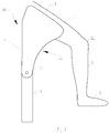
- Fig. 1 is a drawing illustrating a walking assist device 100 having a shank link 101 and a thigh member 102 rotatably connected to each other at a knee mechanism 103.
- Thigh member 102 is configurable to be in contact with the person's thigh 109.
- knee mechanism 103 is resisting the motion (i.e., rotation) of shank link 101 relative to thigh member 102, thereby preventing the person's foot 110 from contacting the ground and reducing the ground reaction force entering the person's foot 110.
- walking assist device 100 operates such that when shank link 101 is not in contact with the ground (i.e., swing phase), the resistance of knee mechanism 103 to the motion (i.e., rotation) of shank link 101 relative to thigh member 102 is less than the resistance of knee mechanism 103 when shank link 101 is in contact with the ground.
- This low resistance allows the person to freely swing walking assist device 100 during the swing phase of a walking cycle.
- knee mechanism 103 is rather inflexible to rotation during the stance phase and flexible to rotation during the swing phase, walking assist device 100 behaves like the person's leg, allowing the person to walk without putting his or her foot 110 on the ground.
- said knee mechanism comprises at least one rotary joint allowing rotary motion between shank link 101 and thigh member 102 during the swing phase.
- said knee mechanism comprises a four-bar mechanism allowing motion (i.e., rotation) between shank link 101 and thigh member 102 during the swing phase.
- thigh member 102 further comprises a thigh link 115 and a thigh support 104, which is in contact with the person's thigh 109 when walking assist device 100 is worn on the person's leg.
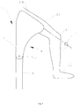
- the orientation of thigh link 115 relative to thigh support 104 (shown by angle A) is fixed.
- angle A can be defined between a center line along thigh link 115, which extends through knee mechanism 103, and a center line along thigh support 104, which approximately parallels a center line along the person's thigh 109.
- the orientation of thigh link 115 relative to thigh support 104 is adjustable, which helps the person to find the most comfortable fit during walking.
- thigh support 104 rotates slightly relative to thigh link 115 during walking.
- the relative motion between thigh support 104 and thigh link 115 has at least one degree of freedom.
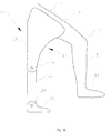
- Angle A shown in Fig. 3 , represents an example of this rotation in the sagittal plane. This slight motion might be needed for some patients to feel less constraint during locomotion.
- Fig. 3 represents an example of this rotation in the sagittal plane. This slight motion might be needed for some patients to feel less constraint during locomotion.
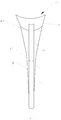
- the relative motion between thigh support 104 and thigh link 115 is configured to have at least one degree of freedom represented by arrow 113, which corresponds to an axis of rotation about the center line along thigh support 104 that approximately parallels the center line along the person's thigh 109.
- the mechanism between thigh support 104 and thigh link 115 is spring loaded.
- spring 130 mounted between thigh support 104 and thigh link 115 to provide some compliancy between the thigh support 104 and the rest of the system.
- walking assist device 100 further comprises a set of straps 108, which are attached to thigh support 104 and which wrap around the person's thigh 109 to fix thigh support 104 to the person's thigh 109.
- walking assist device 100 further comprises a connecting link 105 which, in operation, couples shank link 101 with the person's leg 111 at a location below the person's knee 112.
- connecting link 105 is a rigid component.
- connecting link 105 is a compliant component to create more comfort for the person.
- connecting link 105 has an adjustable length.
- connecting link 105 is coupled with shank link 101 at a location that is adjustable. This link provides an extra level of security or stability of the person's leg.
- walking assist device 100 further comprises an artificial foot 106 coupled to shank link 101.
- walking assist device 100 further comprises an ankle joint 107 between shank link 101 and artificial foot 106.
- knee mechanism 103 may be hydraulically damped to be resistant to the movement of shank link 101 with respect to thigh member 102 when shank link 101 is in contact with the ground, and then to be less resistant to this motion when shank link 101 is not in contact with the ground.
- knee mechanism 103 is powered by a motor 131 to assist in ambulating.
- walking assist device 100 (as shown in Fig. 11 ) comprises a torque generator 114, which is configured to allow flexion of knee mechanism 103 during swing phase and to resist flexion of knee mechanism 103 during stance phase, thereby allowing walking assist device 100 to bear the person's weight and transfer the forces (e.g., the person's weight) to the ground.
- a torque generator 114 which is configured to allow flexion of knee mechanism 103 during swing phase and to resist flexion of knee mechanism 103 during stance phase, thereby allowing walking assist device 100 to bear the person's weight and transfer the forces (e.g., the person's weight) to the ground.
- torque generator 114 is a hydraulic torque generator.
- torque generator 114 is a hydraulic piston cylinder where the motion of the piston relative to the cylinder creates hydraulic fluid flow into or out of the cylinder. In operation, the hydraulic fluid flow into or out of the cylinder may be controlled by a hydraulic valve.
- torque generator 114 is a friction brake where one can control the resistive torque on knee mechanism 103 by controlling the friction torque.
- torque generator 114 is a viscosity-based friction brake where one can control the resistive torque on knee mechanism 103 by controlling the viscosity of the fluid.
- torque generator 114 is a Magnetorheological Fluid Device where one can control the resistive torque on knee mechanism 103 by controlling the viscosity of the Magnetorheological Fluid.
- torque generator 114 is a Magnetorheological Fluid Device where one can control the resistive torque on knee mechanism 103 by controlling the viscosity of the Magnetorheological Fluid.
- Knee mechanism 103 in some cases, is a locking joint that locks during the stance phase (i.e., does not bend) when vertical force is imposed on it.
- This type of knee mechanism is described in U.S. patent no. 3,863,274 , which is incorporated herein by reference in its entirety for all purposes.
- Another example of a knee mechanism that locks during stance is described in U.S. patent no. 5,755,813 , which is incorporated herein by reference in its entirety for all purposes.
- One experienced in the art can design all kinds of single-axis or polycentric knee mechanisms that lock or damp during stance.
- thigh member 102 will have a fixed length 116. In some embodiments, thigh member 102 will have an adjustable length 116 to fit various individuals. In some embodiments, as shown in Fig. 13 , thigh member 102 comprises thigh link 115 and thigh support 104 coupled together through a compliant element 117 to absorb and filter shock forces during stance phase. In some embodiments, as shown in Fig. 14 , shank link 101 will have a fixed length 118. In some embodiments, shank link 101 will have an adjustable length 118 to fit various individuals. In some embodiments, as shown in Fig. 15 , shank link 101 comprises at least two components 119 and 120 coupled together through a compliant element 121 to absorb and filter shock forces during stance phase.
- walking assist device 100 is located behind the person's leg 111. In some other embodiments, as shown in Fig. 17 , walking assist device 100 is configured to be located to the side of the person's leg 111.
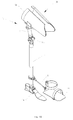
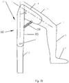
- FIGs. 18 and 19 are drawings illustrating a walking assist device 100, which was built for evaluation.
- Walking assist device 100 comprises a shank link 101 and a thigh member 102 rotatably connected to each other at a knee mechanism 103.
- Thigh member 102 further comprises a thigh link 115 and a thigh support 104, which is in contact with the person's thigh.
- Thigh link 115 and shank link 101 are made of extruded aluminum tubes.
- Artificial foot 106 is coupled to shank link 101.
- Connecting link 105 couples shank link 101 to the person's leg at a location below the person's knee.
- connecting link 105 couples shank link 101 to foot support 122, which can be attached to the person's foot.
- knee mechanism 103 In operation when walking assist device 100 is in contact with the ground (i.e., stance phase) through its shank link 101, knee mechanism 103 will be locked to resist the motion of shank link 101 relative to thigh member 102, thereby preventing the person's foot from contacting the ground and reducing the ground reaction force entering the person's foot.
- Knee mechanism 103 in this case is a locking joint that locks (i.e., does not bend) when force is imposed on it.
- this type of knee mechanism is described in U.S. patent no. 3,863,274 , which is incorporated herein by reference in its entirety for all purposes.
- Another example of a knee mechanism that locks during stance is described in U.S. patent no. 5,755,813 , which is incorporated herein by reference in its entirety for all purposes.
- One experienced in the art can design all kinds of single-axis or polycentric knee mechanisms that lock or damp during stance.
Landscapes
- Health & Medical Sciences (AREA)
- Epidemiology (AREA)
- Pain & Pain Management (AREA)
- Physical Education & Sports Medicine (AREA)
- Rehabilitation Therapy (AREA)
- Life Sciences & Earth Sciences (AREA)
- Animal Behavior & Ethology (AREA)
- General Health & Medical Sciences (AREA)
- Public Health (AREA)
- Veterinary Medicine (AREA)
- Rehabilitation Tools (AREA)
Description
- The present application relates generally to walking assist devices that assist in walking post-injury.
- Crutches are medical devices used when a person has an injured leg or is otherwise unable to use his or her leg. Conventional crutches generally have a single degree of freedom and two endpoints. One endpoint contacts the ground, while the other makes contact with some part of the person's upper body, such as the underarm, and is held by the user's hand. Conventional crutches function by allowing users to put their weight into the crutches, bypassing the injured leg entirely. There are many different kinds of crutches currently on the market; they vary in quality and ergonomic support, and therefore in price. The two most commonly used types are underarm and forearm crutches.
- There are many disadvantages to using conventional crutches. The first disadvantage of using conventional crutches is that one must hold onto them, thereby restricting the use of one's hands for other purposes. It is very difficult to walk, stand up, sit down, open and close doors, and climb stairs using crutches. It takes approximately twice the energy to walk with crutches as to walk without them.
(See, Fisher, S.V., Patterson, RP (1981); Energy cost of ambulation with crutches; Archives of physical medicine and rehabilitation, 62, 250-56.) Conventional crutches depend highly on the user's upper arm strength, which for weak or elderly patients may be a problem. Another problem with conventional crutches is that patients tend to rest their body weight on the axillary pad of the crutch, thereby applying undue pressure. (See, McFall, B., Arya, N., Soong, C., Lee, B. & Hannon, R. (2004); Crutch induced axillary artery injury; The Ulster Medical Journal, 73, 50-52.) This pressure damages the arteries in the axillary region. (See, Feldman, D., Vujic, I., McKay, D., Callcott, F. & Uflacker, R. (1995); Crutch-induced axillary artery injury; Journal of Cardiovascular and Interventional Radiology, 18, 296-99.) Nerve damage can also result. (See, "Crutch Fitting and Walking"; University of North Carolina at Chapel Hill: Campus Health Services; 2006; <http://campushealth.unc.edu/index.php?option=com_content&task=view&id=102&I temid=65>.) - One technological development that has attempted to replace the crutch, as opposed to redesigning it, is called the "iWALKFree". (See, "iWALKFree High Performance Rehabilitation Device - Hands-free Crutch"; Health Check Systems; 2004; <http://www.healthchecksystems.com/i_walk_free.htm>.) This device works by being attached to the thigh while resting the knee, in a bent position, on a flat platform. The "iWALKFree" has the advantage of leaving the hands free, but seems to force the leg to stay in a single, awkwardly bent position. The ground reaction forces are transferred away from the foot of the injured leg and directly into the person's knee joint. With the knee bent, the person's center of mass will be shifted backwards, potentially causing instability. Additionally, the iWALKfree does not contain a knee-like joint, giving it zero degrees of freedom. This "peg-leg" type of design causes the user to experience an abnormal and potentially jarring gait cycle. The design of this device leaves much to be improved upon, while its existence suggests that there exists a need for an alternative to crutches.
-
US 2 827 897 A discloses an articulated leg brace comprising a hollow post, a pair of struts pivotally secured to said post, locking means for locking said struts against pivotal movement with respect to said post, a saddle member pivotally secured to said struts, a rod telescopically secured in said post and pivotally connected to said saddle member, a pair of brace members pivotally secured to said saddle member, a covering member secured to said saddle member and adapted to cover and embrace the kneecap of the person, and an ankle joint saddle pivotally secured to the lower end of said brace members. - The overall design of the device disclosed in
US 2 827 897 A disadvantageously transfers significant reaction forces to each of the user's foot, saddle member and the user's thigh, due to the incorporation of a brace member. No corresponding brace member is provided in accordance with the present invention, in which the shank link is only connected to the thigh support through the knee mechanism and the thigh link and optionally connected through a connecting link coupling the shank link with the person's leg at a location below the person's knee and above the person's ankle when the device is worn on the person's leg. -
WO 99/08645 - According to the present invention there is provided the walking assist device of claim 1.
- Additional aspects of the invention are set out in the dependent claims.
- These and other features, aspects, and advantages of the present invention will become better understood when the following detailed description is read with reference to the accompanying drawings in which like characters represent like parts throughout the drawings, wherein:
-
Figs. 1 and2 depict an exemplary embodiment of a walking assist device attached to a person's leg. -
Fig. 3 depicts another embodiment of a walking assist device. -
Fig. 4 depicts another embodiment of a walking assist device. -
Fig. 5 depicts an embodiment of the walking assist device with a set of straps, which wrap around the person's thigh. -
Fig. 6 depicts another embodiment of a walking assist device with a connecting link. -
Fig. 7 depicts another embodiment of a walking assist device with an adjustable connecting link. -
Fig. 8 depicts another embodiment of a walking assist device with a connecting link coupled with a shank link at an adjustable location. -
Fig. 9 depicts another embodiment of a walking assist device with an artificial foot. -
Fig. 10 depicts another embodiment of a walking assist device with an ankle joint between its shank link and an artificial foot. -
Fig. 11 depicts another embodiment of a walking assist device with a torque generator. -
Fig. 12 depicts another embodiment of a walking assist device with a thigh member that has a fixed length. -
Fig. 13 depicts another embodiment of a walking assist device with a thigh link and thigh support coupled together through a compliant element. -
Fig. 14 depicts another embodiment of a walking assist device with a shank link that has a fixed length. -
Fig. 15 depicts another embodiment of a walking assist device with a shank link that has at least two components coupled together through a compliant element. -
Fig. 16 depicts another embodiment of a walking assist device that is configured to be located behind the person's leg. -
Fig. 17 depicts another embodiment of a walking assist device that is configured to be located to the side of the person's leg. -
Fig. 18 is an isometric view of an exemplary walking assist device. -
Fig. 19 is a side view of the walking assist device depicted inFig. 18 . -
Fig. 20 depicts another embodiment of a walking assist device with a spring mounted between the thigh support and the thigh link. -
Fig. 21 depicts another embodiment of a walking assist device with the knee mechanism powered by a motor. - In accordance with one exemplary embodiment,
Fig. 1 is a drawing illustrating awalking assist device 100 having ashank link 101 and athigh member 102 rotatably connected to each other at aknee mechanism 103. Thighmember 102 is configurable to be in contact with the person'sthigh 109. In operation, whenwalking assist device 100 is in contact with the ground through its shank link 101 (i.e., stance phase),knee mechanism 103 is resisting the motion (i.e., rotation) ofshank link 101 relative tothigh member 102, thereby preventing the person'sfoot 110 from contacting the ground and reducing the ground reaction force entering the person'sfoot 110. - In some embodiments, as shown in
Fig. 1 , walking assistdevice 100 operates such that whenshank link 101 is not in contact with the ground (i.e., swing phase), the resistance ofknee mechanism 103 to the motion (i.e., rotation) ofshank link 101 relative tothigh member 102 is less than the resistance ofknee mechanism 103 whenshank link 101 is in contact with the ground. This low resistance allows the person to freely swing walkingassist device 100 during the swing phase of a walking cycle. In effect, sinceknee mechanism 103 is rather inflexible to rotation during the stance phase and flexible to rotation during the swing phase, walking assistdevice 100 behaves like the person's leg, allowing the person to walk without putting his or herfoot 110 on the ground. - In some embodiments, said knee mechanism comprises at least one rotary joint allowing rotary motion between
shank link 101 andthigh member 102 during the swing phase. In some embodiments, said knee mechanism comprises a four-bar mechanism allowing motion (i.e., rotation) betweenshank link 101 andthigh member 102 during the swing phase. One experienced in the design of mechanisms can develop various kinds ofknee mechanism 103 to create knee-like motion betweenshank link 101 andthigh member 102. - In some embodiments, as shown in
Fig. 1 ,thigh member 102 further comprises athigh link 115 and athigh support 104, which is in contact with the person'sthigh 109 when walkingassist device 100 is worn on the person's leg. In some embodiments, as shown inFig. 2 , the orientation ofthigh link 115 relative to thigh support 104 (shown by angle A) is fixed. In particular, as shown inFig. 3 , angle A can be defined between a center line alongthigh link 115, which extends throughknee mechanism 103, and a center line alongthigh support 104, which approximately parallels a center line along the person'sthigh 109. In some embodiments, the orientation ofthigh link 115 relative tothigh support 104 is adjustable, which helps the person to find the most comfortable fit during walking. - In some embodiments, as shown in
Fig. 3 ,thigh support 104 rotates slightly relative tothigh link 115 during walking. In some embodiments, the relative motion betweenthigh support 104 andthigh link 115 has at least one degree of freedom. Angle A, shown inFig. 3 , represents an example of this rotation in the sagittal plane. This slight motion might be needed for some patients to feel less constraint during locomotion. In some other embodiments, as shown inFig. 4 , the relative motion betweenthigh support 104 andthigh link 115 is configured to have at least one degree of freedom represented byarrow 113, which corresponds to an axis of rotation about the center line alongthigh support 104 that approximately parallels the center line along the person'sthigh 109. To create further comfort, in some embodiments as shown inFig. 20 , the mechanism betweenthigh support 104 andthigh link 115 is spring loaded. In one embodiment,spring 130 mounted betweenthigh support 104 and thigh link 115 to provide some compliancy between thethigh support 104 and the rest of the system. In some embodiments, as shown inFig. 5 , walking assistdevice 100 further comprises a set ofstraps 108, which are attached tothigh support 104 and which wrap around the person'sthigh 109 to fixthigh support 104 to the person'sthigh 109. - In some embodiments, as shown in
Fig. 6 , walking assistdevice 100 further comprises a connectinglink 105 which, in operation, couples shank link 101 with the person'sleg 111 at a location below the person'sknee 112. In some embodiments, as shown inFig. 6 , connectinglink 105 is a rigid component. In some embodiments, connectinglink 105 is a compliant component to create more comfort for the person. In some embodiments, as shown inFig. 7 , connectinglink 105 has an adjustable length. In some embodiments, as shown inFig. 8 , connectinglink 105 is coupled withshank link 101 at a location that is adjustable. This link provides an extra level of security or stability of the person's leg. - In some embodiments, as shown in
Fig. 9 , walking assistdevice 100 further comprises anartificial foot 106 coupled toshank link 101. In some embodiments, as shown inFig. 10 , walking assistdevice 100 further comprises an ankle joint 107 betweenshank link 101 andartificial foot 106. - In some embodiments, as shown in
Fig. 11 ,knee mechanism 103 may be hydraulically damped to be resistant to the movement ofshank link 101 with respect tothigh member 102 whenshank link 101 is in contact with the ground, and then to be less resistant to this motion whenshank link 101 is not in contact with the ground. In some embodiments, as shown inFig. 21 ,knee mechanism 103 is powered by amotor 131 to assist in ambulating. - In some embodiments, walking assist device 100 (as shown in
Fig. 11 ) comprises atorque generator 114, which is configured to allow flexion ofknee mechanism 103 during swing phase and to resist flexion ofknee mechanism 103 during stance phase, thereby allowing walking assistdevice 100 to bear the person's weight and transfer the forces (e.g., the person's weight) to the ground. - In some embodiments,
torque generator 114 is a hydraulic torque generator. In accordance with some embodiments,torque generator 114 is a hydraulic piston cylinder where the motion of the piston relative to the cylinder creates hydraulic fluid flow into or out of the cylinder. In operation, the hydraulic fluid flow into or out of the cylinder may be controlled by a hydraulic valve. In some embodiments,torque generator 114 is a friction brake where one can control the resistive torque onknee mechanism 103 by controlling the friction torque. In other embodiments,torque generator 114 is a viscosity-based friction brake where one can control the resistive torque onknee mechanism 103 by controlling the viscosity of the fluid. In other embodiments,torque generator 114 is a Magnetorheological Fluid Device where one can control the resistive torque onknee mechanism 103 by controlling the viscosity of the Magnetorheological Fluid. One skilled in the art realizes that any of the above devices can be mounted in the invention to function in the same way as the hydraulic damper shown inFig. 11 . -
Knee mechanism 103, in some cases, is a locking joint that locks during the stance phase (i.e., does not bend) when vertical force is imposed on it. This type of knee mechanism is described inU.S. patent no. 3,863,274 , which is incorporated herein by reference in its entirety for all purposes. Another example of a knee mechanism that locks during stance is described inU.S. patent no. 5,755,813 , which is incorporated herein by reference in its entirety for all purposes. One experienced in the art can design all kinds of single-axis or polycentric knee mechanisms that lock or damp during stance. - In some embodiments, as shown in
Fig. 12 ,thigh member 102 will have a fixedlength 116. In some embodiments,thigh member 102 will have anadjustable length 116 to fit various individuals. In some embodiments, as shown inFig. 13 ,thigh member 102 comprisesthigh link 115 andthigh support 104 coupled together through acompliant element 117 to absorb and filter shock forces during stance phase. In some embodiments, as shown inFig. 14 ,shank link 101 will have a fixedlength 118. In some embodiments,shank link 101 will have anadjustable length 118 to fit various individuals. In some embodiments, as shown inFig. 15 ,shank link 101 comprises at least twocomponents 119 and 120 coupled together through acompliant element 121 to absorb and filter shock forces during stance phase. - In some embodiments, as shown in
Fig. 16 , walking assistdevice 100 is located behind the person'sleg 111. In some other embodiments, as shown inFig. 17 , walking assistdevice 100 is configured to be located to the side of the person'sleg 111. - In accordance with an embodiment of the present invention,
Figs. 18 and19 are drawings illustrating awalking assist device 100, which was built for evaluation. Walking assistdevice 100 comprises ashank link 101 and athigh member 102 rotatably connected to each other at aknee mechanism 103.Thigh member 102 further comprises athigh link 115 and athigh support 104, which is in contact with the person's thigh.Thigh link 115 andshank link 101 are made of extruded aluminum tubes.Artificial foot 106, with a spring action, is coupled toshank link 101. Connecting link 105 couples shank link 101 to the person's leg at a location below the person's knee. In particular, connecting link 105 couples shank link 101 tofoot support 122, which can be attached to the person's foot. - In operation when walking
assist device 100 is in contact with the ground (i.e., stance phase) through itsshank link 101,knee mechanism 103 will be locked to resist the motion ofshank link 101 relative tothigh member 102, thereby preventing the person's foot from contacting the ground and reducing the ground reaction force entering the person's foot.Knee mechanism 103 in this case is a locking joint that locks (i.e., does not bend) when force is imposed on it. As mentioned above, this type of knee mechanism is described inU.S. patent no. 3,863,274 , which is incorporated herein by reference in its entirety for all purposes. Another example of a knee mechanism that locks during stance is described inU.S. patent no. 5,755,813 , which is incorporated herein by reference in its entirety for all purposes. One experienced in the art can design all kinds of single-axis or polycentric knee mechanisms that lock or damp during stance. - Although various exemplary embodiments have been described, it will be appreciated by persons skilled in the art that numerous variations and/or modifications may be made to the described device as specifically shown here without departing from the spirit or scope of that broader disclosure. The various examples are, therefore, to be considered in all respects as illustrative and not restrictive. The invention is only intended to be limited by the scope of the following claims.
Claims (15)
- A walking assist device (100) to be worn on a person's leg, the device comprising:a shank link (101);a thigh member (102) including a thigh support (104), which is in contact with the person's thigh when the device is worn on the person's leg, and a thigh link (115) connected to the thigh support; anda knee mechanism (103) that rotatably connects said shank link to the thigh link of said thigh member, with the shank link only being connected to the thigh support through the knee mechanism and the thigh link and optionally connected through a connecting link (105) coupling said shank link (101) with the person's leg at a location below the person's knee and above the person's ankle when the device (100) is worn on the person's leg, wherein when the device (100) is worn on the person's leg and the person is walking:when said shank link is in contact with the ground, said knee mechanism is configured to resist the rotation of said shank link relative to said thigh member to prevent the person's foot from contacting the ground, andwhen said shank link (101) is not in contact with the ground, said knee mechanism's resistance to the rotation of said shank link relative to said thigh member (102) is less than said knee mechanism's resistance when said shank link is in contact with the ground.
- The walking assist device of claim 1, wherein the orientation of said thigh link (115) relative to said thigh support (104) is fixed or adjustable.
- The walking assist device of claim 1, wherein said thigh support (104) is either:rigidly connected to the person's thigh, preventing relative motion between said thigh support and the person's thigh when the device (100) is worn on the person's leg; orrotates slightly relative to said thigh link (115) during walking.
- The walking assist device of claim 1, wherein said thigh support (104) rotates slightly relative to said thigh link (115) during walking, and wherein either:the relative motion between said thigh support and said thigh link has at least one degree of freedom; orthe relative motion between said thigh support and said thigh link is provided by a spring (103).
- The walking assist device of claim 1, further comprising straps (108) which are attached to said thigh support (104) and wrap around the person's thigh to fix said thigh support to the person's thigh when the device (100) is worn on the person's leg.
- The walking assist device of claim 1, wherein:said connecting link (105) is a rigid component; orsaid connecting link is a compliant component; orsaid connecting link has an adjustable length; orsaid connecting link is coupled with said shank link at an adjustable location.
- The walking assist device of claim 1, further comprising an artificial foot (106) coupled to said shank link (101).
- The walking assist device of claim 7, wherein said walking assist device (100) further comprises an ankle joint (107) located between said shank link and said artificial foot.
- The walking assist device of claim 1, wherein said knee mechanism (103):is hydraulically damped to be resistant to the movement of said shank link (101) with respect to said thigh member (102) when said shank link is in contact with the ground, and then to be less resistant to this motion when said shank link is not in contact with the ground; oris powered by a motor (131) to assist in ambulating; orcomprises at least one rotary joint allowing rotary motion between said shank link and said thigh member during the swing phase when said shank link is not in contact with the ground.
- The walking assist device of claim 1, wherein said knee mechanism comprises a four-bar mechanism allowing rotary motion between said shank link (101) and said thigh member (102) during the swing phase when said shank link is not in contact with the ground.
- The walking assist device of claim 1, further comprising:a torque generator (114) configured to allow flexion of said knee mechanism (103) during swing phase and to resist flexion of said knee mechanism during stance phase to allow the transfer of forces to the ground, wherein said shank link (101) is not in contact with the ground in said swing phase, and wherein said shank link is in contact with the ground in said stance phase, optionally wherein said torque generator is either:a hydraulic piston cylinder, wherein the hydraulic piston cylinder's resistive force can be controlled by controlling the fluid flow through a hydraulic valve; orselected from a group consisting of friction brakes, viscosity-based friction brakes, and Magnetorheological Fluid Devices.
- The walking assist device of claim 1, wherein the thigh support (104) and the thigh link (115) are coupled together through a compliant element (117) to absorb and filter shock forces during stance phase when the shank link (101) is in contact with the ground.
- The walking assist device of claim 1, wherein said shank link (101):has a fixed length; orhas an adjustable length; orcomprises at least two components coupled together through a compliant element to absorb and filter shock forces during stance phase when the shank link is in contact with the ground.
- The walking assist device of claim 1, wherein said shank link (101) and thigh member (102) are either:located behind the person's leg when the device (100) is worn on the person's leg; orlocated to the side of the person's leg when the device is worn on the person's leg.
- The walking assist device of claim 1, wherein the knee mechanism (103) is configured to move in flexion during a swing phase, wherein the knee mechanism is configured to resist flexion during a stance phase, wherein the shank link (101) is not in contact with the ground during the swing phase, and wherein the shank link is in contact with the ground during the stance phase.
Applications Claiming Priority (2)
| Application Number | Priority Date | Filing Date | Title |
|---|---|---|---|
| US6079108P | 2008-06-11 | 2008-06-11 | |
| PCT/US2009/047117 WO2009152386A1 (en) | 2008-06-11 | 2009-06-11 | External walking assist device for those with lower leg injuries |
Publications (3)
| Publication Number | Publication Date |
|---|---|
| EP2299962A1 EP2299962A1 (en) | 2011-03-30 |
| EP2299962A4 EP2299962A4 (en) | 2012-03-21 |
| EP2299962B1 true EP2299962B1 (en) | 2018-12-12 |
Family
ID=41417130
Family Applications (1)
| Application Number | Title | Priority Date | Filing Date |
|---|---|---|---|
| EP09763674.0A Active EP2299962B1 (en) | 2008-06-11 | 2009-06-11 | External walking assist device for those with lower leg injuries |
Country Status (7)
| Country | Link |
|---|---|
| US (1) | US8257291B2 (en) |
| EP (1) | EP2299962B1 (en) |
| CN (1) | CN102056579B (en) |
| AU (1) | AU2009257402B2 (en) |
| CA (1) | CA2727292C (en) |
| IL (1) | IL209063A0 (en) |
| WO (1) | WO2009152386A1 (en) |
Families Citing this family (21)
| Publication number | Priority date | Publication date | Assignee | Title |
|---|---|---|---|---|
| US8075429B2 (en) * | 2007-04-11 | 2011-12-13 | Wilson Sporting Goods Co. | Racquet stringing machine |
| CA2724085C (en) | 2008-05-20 | 2018-10-16 | Berkeley Bionics | Device and method for decreasing energy consumption of a person by use of a lower extremity exoskeleton |
| US9351855B2 (en) | 2008-06-16 | 2016-05-31 | Ekso Bionics, Inc. | Powered lower extremity orthotic and method of operation |
| US20110196509A1 (en) * | 2009-02-27 | 2011-08-11 | Ut-Battelle, Llc | Hydraulic apparatus with direct torque control |
| US9333644B2 (en) | 2010-04-09 | 2016-05-10 | Lockheed Martin Corporation | Portable load lifting system |
| US20120290102A1 (en) * | 2011-05-11 | 2012-11-15 | Mahoney Ormonde M | Knee Crutch System |
| US20130184616A1 (en) * | 2011-09-29 | 2013-07-18 | Michael R. Sanders | Mobility device |
| CA2902074A1 (en) | 2013-03-13 | 2014-10-09 | Ekso Bionics, Inc. | Gait orthotic system and method for achieving hands-free stability |
| CN103462738A (en) * | 2013-10-09 | 2013-12-25 | 四川大学 | Walking aid replacing crutch |
| US10561568B1 (en) | 2014-06-19 | 2020-02-18 | Lockheed Martin Corporation | Exoskeleton system providing for a load transfer when a user is standing and kneeling |
| US10548800B1 (en) | 2015-06-18 | 2020-02-04 | Lockheed Martin Corporation | Exoskeleton pelvic link having hip joint and inguinal joint |
| US10195736B2 (en) | 2015-07-17 | 2019-02-05 | Lockheed Martin Corporation | Variable force exoskeleton hip joint |
| US10518404B2 (en) | 2015-07-17 | 2019-12-31 | Lockheed Martin Corporation | Variable force exoskeleton hip joint |
| US10912346B1 (en) | 2015-11-24 | 2021-02-09 | Lockheed Martin Corporation | Exoskeleton boot and lower link |
| US10124484B1 (en) | 2015-12-08 | 2018-11-13 | Lockheed Martin Corporation | Load-bearing powered exoskeleton using electromyographic control |
| US10441493B2 (en) * | 2016-10-21 | 2019-10-15 | Purdue Research Foundation | Mobility device |
| CA3073504A1 (en) | 2017-08-30 | 2019-03-07 | Lockheed Martin Corporation | Automatic sensor selection |
| US11446200B1 (en) * | 2018-09-30 | 2022-09-20 | Eli Razon | Assisted walking device for human paralysis or weakness |
| CN114469654B (en) * | 2020-11-13 | 2024-02-13 | 复旦大学 | Stepless regulation's hand-free low limbs walking Kang Fufu utensil |
| US12336954B2 (en) | 2022-01-26 | 2025-06-24 | Eazistep, Llc | Hybrid hands-free crutch |
| US12011413B2 (en) | 2022-04-13 | 2024-06-18 | Annbri, LLC | Seated walker |
Family Cites Families (8)
| Publication number | Priority date | Publication date | Assignee | Title |
|---|---|---|---|---|
| US2827897A (en) | 1956-05-14 | 1958-03-25 | Zygmunt A Pawlowski | Articulated leg brace |
| US4058119A (en) | 1976-08-12 | 1977-11-15 | Rosequist Craig D | Walking device |
| US5020790A (en) * | 1990-10-23 | 1991-06-04 | Board Of Supervisors Of Louisiana State University And Agricultural And Mechanical College | Powered gait orthosis |
| US5300016A (en) | 1992-04-14 | 1994-04-05 | Marlatt William W | Lower leg shelf with foldable weight-bearing strut and stabilizer frame |
| GB9717573D0 (en) | 1997-08-20 | 1997-10-22 | Lewis Craig E | Mobility aid |
| US5913901A (en) * | 1998-05-26 | 1999-06-22 | Lacroix; Barry | Ankle joint prosthesis |
| SE518726C2 (en) * | 1999-11-23 | 2002-11-12 | Gramtec Innovation Ab | Device for knee joint prosthesis comprising polycentric link mechanism |
| US7485152B2 (en) * | 2005-08-26 | 2009-02-03 | The Ohio Willow Wood Company | Prosthetic leg having electronically controlled prosthetic knee with regenerative braking feature |
-
2009
- 2009-06-11 CN CN200980121468.3A patent/CN102056579B/en active Active
- 2009-06-11 EP EP09763674.0A patent/EP2299962B1/en active Active
- 2009-06-11 US US12/483,183 patent/US8257291B2/en active Active
- 2009-06-11 AU AU2009257402A patent/AU2009257402B2/en active Active
- 2009-06-11 CA CA 2727292 patent/CA2727292C/en active Active
- 2009-06-11 WO PCT/US2009/047117 patent/WO2009152386A1/en not_active Ceased
-
2010
- 2010-11-01 IL IL209063A patent/IL209063A0/en active IP Right Grant
Non-Patent Citations (1)
| Title |
|---|
| None * |
Also Published As
| Publication number | Publication date |
|---|---|
| AU2009257402B2 (en) | 2013-08-29 |
| US8257291B2 (en) | 2012-09-04 |
| EP2299962A4 (en) | 2012-03-21 |
| EP2299962A1 (en) | 2011-03-30 |
| WO2009152386A1 (en) | 2009-12-17 |
| IL209063A0 (en) | 2011-01-31 |
| CN102056579B (en) | 2015-02-18 |
| CA2727292C (en) | 2015-03-31 |
| CA2727292A1 (en) | 2009-12-17 |
| CN102056579A (en) | 2011-05-11 |
| US20100010641A1 (en) | 2010-01-14 |
| AU2009257402A1 (en) | 2009-12-17 |
Similar Documents
| Publication | Publication Date | Title |
|---|---|---|
| CA2727292C (en) | External walking assist device for those with lower leg injuries | |
| CN101132753B (en) | Lower extremity exoskeleton | |
| JP3923859B2 (en) | Extracorporeal torsion device | |
| US9918892B2 (en) | External structural brace apparatus | |
| US10441493B2 (en) | Mobility device | |
| CN111920655B (en) | Ankle joint device with adjustable initial angle of foot support | |
| US7303537B1 (en) | Ambulation assistance device | |
| AU2009282397A1 (en) | Device and method for decreasing oxygen consumption of a person during steady walking by use of a load-carrying exoskeleton | |
| JP2016528019A (en) | Wearable posture assistive device | |
| CA2544901A1 (en) | Prosthetic knee joint | |
| EP2967960B1 (en) | Dynamic force hinge joint for knee brace and knee brace equipped therewith | |
| US20180093125A1 (en) | Mobile upper extremity (ue) supports for use in railed environments: crossover arm design assembly and unilateral ue support designs | |
| CN113580100A (en) | Passive type load-bearing maneuvering exoskeleton | |
| JP2017511180A (en) | Leg augmentation system and method of use | |
| CN114667119A (en) | Device for supporting the back of a user | |
| JP2025081539A (en) | Hip exoskeleton structure for lifting and pushing | |
| US5402587A (en) | Hinged flexible walker assembly | |
| EP0704194A1 (en) | Hip joint for orthopedic orthesis | |
| EP2289478A1 (en) | A-frame walker | |
| RU2110243C1 (en) | Exoskeleton | |
| RU2635760C1 (en) | Tibial link of orthesis or exoskeleton | |
| KR20220146114A (en) | Hands-free crutches that allow free and natural walking according to the theory of walking | |
| CN210785275U (en) | Medical rehabilitation auxiliary walker for ankle orthopedics | |
| JP4214216B2 (en) | Elderly person experience simulator | |
| WO2017068585A1 (en) | Booster device for muscles |
Legal Events
| Date | Code | Title | Description |
|---|---|---|---|
| PUAI | Public reference made under article 153(3) epc to a published international application that has entered the european phase |
Free format text: ORIGINAL CODE: 0009012 |
|
| 17P | Request for examination filed |
Effective date: 20110110 |
|
| AK | Designated contracting states |
Kind code of ref document: A1 Designated state(s): AT BE BG CH CY CZ DE DK EE ES FI FR GB GR HR HU IE IS IT LI LT LU LV MC MK MT NL NO PL PT RO SE SI SK TR |
|
| AX | Request for extension of the european patent |
Extension state: AL BA RS |
|
| DAX | Request for extension of the european patent (deleted) | ||
| A4 | Supplementary search report drawn up and despatched |
Effective date: 20120222 |
|
| RIC1 | Information provided on ipc code assigned before grant |
Ipc: A61H 3/00 20060101AFI20120216BHEP |
|
| 17Q | First examination report despatched |
Effective date: 20131213 |
|
| GRAP | Despatch of communication of intention to grant a patent |
Free format text: ORIGINAL CODE: EPIDOSNIGR1 |
|
| STAA | Information on the status of an ep patent application or granted ep patent |
Free format text: STATUS: GRANT OF PATENT IS INTENDED |
|
| INTG | Intention to grant announced |
Effective date: 20180627 |
|
| GRAS | Grant fee paid |
Free format text: ORIGINAL CODE: EPIDOSNIGR3 |
|
| GRAA | (expected) grant |
Free format text: ORIGINAL CODE: 0009210 |
|
| STAA | Information on the status of an ep patent application or granted ep patent |
Free format text: STATUS: THE PATENT HAS BEEN GRANTED |
|
| AK | Designated contracting states |
Kind code of ref document: B1 Designated state(s): AT BE BG CH CY CZ DE DK EE ES FI FR GB GR HR HU IE IS IT LI LT LU LV MC MK MT NL NO PL PT RO SE SI SK TR |
|
| REG | Reference to a national code |
Ref country code: GB Ref legal event code: FG4D |
|
| REG | Reference to a national code |
Ref country code: CH Ref legal event code: EP |
|
| REG | Reference to a national code |
Ref country code: AT Ref legal event code: REF Ref document number: 1075044 Country of ref document: AT Kind code of ref document: T Effective date: 20181215 |
|
| REG | Reference to a national code |
Ref country code: DE Ref legal event code: R096 Ref document number: 602009056177 Country of ref document: DE |
|
| REG | Reference to a national code |
Ref country code: IE Ref legal event code: FG4D |
|
| REG | Reference to a national code |
Ref country code: NL Ref legal event code: MP Effective date: 20181212 |
|
| REG | Reference to a national code |
Ref country code: LT Ref legal event code: MG4D |
|
| PG25 | Lapsed in a contracting state [announced via postgrant information from national office to epo] |
Ref country code: ES Free format text: LAPSE BECAUSE OF FAILURE TO SUBMIT A TRANSLATION OF THE DESCRIPTION OR TO PAY THE FEE WITHIN THE PRESCRIBED TIME-LIMIT Effective date: 20181212 Ref country code: LT Free format text: LAPSE BECAUSE OF FAILURE TO SUBMIT A TRANSLATION OF THE DESCRIPTION OR TO PAY THE FEE WITHIN THE PRESCRIBED TIME-LIMIT Effective date: 20181212 Ref country code: NO Free format text: LAPSE BECAUSE OF FAILURE TO SUBMIT A TRANSLATION OF THE DESCRIPTION OR TO PAY THE FEE WITHIN THE PRESCRIBED TIME-LIMIT Effective date: 20190312 Ref country code: FI Free format text: LAPSE BECAUSE OF FAILURE TO SUBMIT A TRANSLATION OF THE DESCRIPTION OR TO PAY THE FEE WITHIN THE PRESCRIBED TIME-LIMIT Effective date: 20181212 Ref country code: BG Free format text: LAPSE BECAUSE OF FAILURE TO SUBMIT A TRANSLATION OF THE DESCRIPTION OR TO PAY THE FEE WITHIN THE PRESCRIBED TIME-LIMIT Effective date: 20190312 Ref country code: HR Free format text: LAPSE BECAUSE OF FAILURE TO SUBMIT A TRANSLATION OF THE DESCRIPTION OR TO PAY THE FEE WITHIN THE PRESCRIBED TIME-LIMIT Effective date: 20181212 Ref country code: LV Free format text: LAPSE BECAUSE OF FAILURE TO SUBMIT A TRANSLATION OF THE DESCRIPTION OR TO PAY THE FEE WITHIN THE PRESCRIBED TIME-LIMIT Effective date: 20181212 |
|
| REG | Reference to a national code |
Ref country code: AT Ref legal event code: MK05 Ref document number: 1075044 Country of ref document: AT Kind code of ref document: T Effective date: 20181212 |
|
| PG25 | Lapsed in a contracting state [announced via postgrant information from national office to epo] |
Ref country code: SE Free format text: LAPSE BECAUSE OF FAILURE TO SUBMIT A TRANSLATION OF THE DESCRIPTION OR TO PAY THE FEE WITHIN THE PRESCRIBED TIME-LIMIT Effective date: 20181212 Ref country code: GR Free format text: LAPSE BECAUSE OF FAILURE TO SUBMIT A TRANSLATION OF THE DESCRIPTION OR TO PAY THE FEE WITHIN THE PRESCRIBED TIME-LIMIT Effective date: 20190313 |
|
| PG25 | Lapsed in a contracting state [announced via postgrant information from national office to epo] |
Ref country code: NL Free format text: LAPSE BECAUSE OF FAILURE TO SUBMIT A TRANSLATION OF THE DESCRIPTION OR TO PAY THE FEE WITHIN THE PRESCRIBED TIME-LIMIT Effective date: 20181212 |
|
| PG25 | Lapsed in a contracting state [announced via postgrant information from national office to epo] |
Ref country code: PL Free format text: LAPSE BECAUSE OF FAILURE TO SUBMIT A TRANSLATION OF THE DESCRIPTION OR TO PAY THE FEE WITHIN THE PRESCRIBED TIME-LIMIT Effective date: 20181212 Ref country code: IT Free format text: LAPSE BECAUSE OF FAILURE TO SUBMIT A TRANSLATION OF THE DESCRIPTION OR TO PAY THE FEE WITHIN THE PRESCRIBED TIME-LIMIT Effective date: 20181212 Ref country code: CZ Free format text: LAPSE BECAUSE OF FAILURE TO SUBMIT A TRANSLATION OF THE DESCRIPTION OR TO PAY THE FEE WITHIN THE PRESCRIBED TIME-LIMIT Effective date: 20181212 Ref country code: PT Free format text: LAPSE BECAUSE OF FAILURE TO SUBMIT A TRANSLATION OF THE DESCRIPTION OR TO PAY THE FEE WITHIN THE PRESCRIBED TIME-LIMIT Effective date: 20190412 |
|
| PG25 | Lapsed in a contracting state [announced via postgrant information from national office to epo] |
Ref country code: EE Free format text: LAPSE BECAUSE OF FAILURE TO SUBMIT A TRANSLATION OF THE DESCRIPTION OR TO PAY THE FEE WITHIN THE PRESCRIBED TIME-LIMIT Effective date: 20181212 Ref country code: IS Free format text: LAPSE BECAUSE OF FAILURE TO SUBMIT A TRANSLATION OF THE DESCRIPTION OR TO PAY THE FEE WITHIN THE PRESCRIBED TIME-LIMIT Effective date: 20190412 Ref country code: RO Free format text: LAPSE BECAUSE OF FAILURE TO SUBMIT A TRANSLATION OF THE DESCRIPTION OR TO PAY THE FEE WITHIN THE PRESCRIBED TIME-LIMIT Effective date: 20181212 Ref country code: SK Free format text: LAPSE BECAUSE OF FAILURE TO SUBMIT A TRANSLATION OF THE DESCRIPTION OR TO PAY THE FEE WITHIN THE PRESCRIBED TIME-LIMIT Effective date: 20181212 |
|
| REG | Reference to a national code |
Ref country code: DE Ref legal event code: R097 Ref document number: 602009056177 Country of ref document: DE |
|
| PLBE | No opposition filed within time limit |
Free format text: ORIGINAL CODE: 0009261 |
|
| STAA | Information on the status of an ep patent application or granted ep patent |
Free format text: STATUS: NO OPPOSITION FILED WITHIN TIME LIMIT |
|
| PG25 | Lapsed in a contracting state [announced via postgrant information from national office to epo] |
Ref country code: SI Free format text: LAPSE BECAUSE OF FAILURE TO SUBMIT A TRANSLATION OF THE DESCRIPTION OR TO PAY THE FEE WITHIN THE PRESCRIBED TIME-LIMIT Effective date: 20181212 Ref country code: DK Free format text: LAPSE BECAUSE OF FAILURE TO SUBMIT A TRANSLATION OF THE DESCRIPTION OR TO PAY THE FEE WITHIN THE PRESCRIBED TIME-LIMIT Effective date: 20181212 Ref country code: AT Free format text: LAPSE BECAUSE OF FAILURE TO SUBMIT A TRANSLATION OF THE DESCRIPTION OR TO PAY THE FEE WITHIN THE PRESCRIBED TIME-LIMIT Effective date: 20181212 |
|
| 26N | No opposition filed |
Effective date: 20190913 |
|
| PG25 | Lapsed in a contracting state [announced via postgrant information from national office to epo] |
Ref country code: MC Free format text: LAPSE BECAUSE OF FAILURE TO SUBMIT A TRANSLATION OF THE DESCRIPTION OR TO PAY THE FEE WITHIN THE PRESCRIBED TIME-LIMIT Effective date: 20181212 |
|
| REG | Reference to a national code |
Ref country code: CH Ref legal event code: PL |
|
| REG | Reference to a national code |
Ref country code: BE Ref legal event code: MM Effective date: 20190630 |
|
| PG25 | Lapsed in a contracting state [announced via postgrant information from national office to epo] |
Ref country code: TR Free format text: LAPSE BECAUSE OF FAILURE TO SUBMIT A TRANSLATION OF THE DESCRIPTION OR TO PAY THE FEE WITHIN THE PRESCRIBED TIME-LIMIT Effective date: 20181212 |
|
| PG25 | Lapsed in a contracting state [announced via postgrant information from national office to epo] |
Ref country code: IE Free format text: LAPSE BECAUSE OF NON-PAYMENT OF DUE FEES Effective date: 20190611 |
|
| PG25 | Lapsed in a contracting state [announced via postgrant information from national office to epo] |
Ref country code: BE Free format text: LAPSE BECAUSE OF NON-PAYMENT OF DUE FEES Effective date: 20190630 Ref country code: LU Free format text: LAPSE BECAUSE OF NON-PAYMENT OF DUE FEES Effective date: 20190611 Ref country code: LI Free format text: LAPSE BECAUSE OF NON-PAYMENT OF DUE FEES Effective date: 20190630 Ref country code: CH Free format text: LAPSE BECAUSE OF NON-PAYMENT OF DUE FEES Effective date: 20190630 |
|
| PG25 | Lapsed in a contracting state [announced via postgrant information from national office to epo] |
Ref country code: FR Free format text: LAPSE BECAUSE OF NON-PAYMENT OF DUE FEES Effective date: 20190630 |
|
| PG25 | Lapsed in a contracting state [announced via postgrant information from national office to epo] |
Ref country code: CY Free format text: LAPSE BECAUSE OF FAILURE TO SUBMIT A TRANSLATION OF THE DESCRIPTION OR TO PAY THE FEE WITHIN THE PRESCRIBED TIME-LIMIT Effective date: 20181212 |
|
| PG25 | Lapsed in a contracting state [announced via postgrant information from national office to epo] |
Ref country code: MT Free format text: LAPSE BECAUSE OF FAILURE TO SUBMIT A TRANSLATION OF THE DESCRIPTION OR TO PAY THE FEE WITHIN THE PRESCRIBED TIME-LIMIT Effective date: 20181212 Ref country code: HU Free format text: LAPSE BECAUSE OF FAILURE TO SUBMIT A TRANSLATION OF THE DESCRIPTION OR TO PAY THE FEE WITHIN THE PRESCRIBED TIME-LIMIT; INVALID AB INITIO Effective date: 20090611 |
|
| PG25 | Lapsed in a contracting state [announced via postgrant information from national office to epo] |
Ref country code: MK Free format text: LAPSE BECAUSE OF FAILURE TO SUBMIT A TRANSLATION OF THE DESCRIPTION OR TO PAY THE FEE WITHIN THE PRESCRIBED TIME-LIMIT Effective date: 20181212 |
|
| PGFP | Annual fee paid to national office [announced via postgrant information from national office to epo] |
Ref country code: DE Payment date: 20250627 Year of fee payment: 17 |
|
| PGFP | Annual fee paid to national office [announced via postgrant information from national office to epo] |
Ref country code: GB Payment date: 20250627 Year of fee payment: 17 |