EP2299564A1 - Cooling structure of motor - Google Patents
Cooling structure of motor Download PDFInfo
- Publication number
- EP2299564A1 EP2299564A1 EP09758065A EP09758065A EP2299564A1 EP 2299564 A1 EP2299564 A1 EP 2299564A1 EP 09758065 A EP09758065 A EP 09758065A EP 09758065 A EP09758065 A EP 09758065A EP 2299564 A1 EP2299564 A1 EP 2299564A1
- Authority
- EP
- European Patent Office
- Prior art keywords
- rotor
- cooling
- stator
- oil
- core
- Prior art date
- Legal status (The legal status is an assumption and is not a legal conclusion. Google has not performed a legal analysis and makes no representation as to the accuracy of the status listed.)
- Withdrawn
Links
- 238000001816 cooling Methods 0.000 title claims abstract description 138
- 230000002093 peripheral effect Effects 0.000 claims abstract description 44
- 238000004804 winding Methods 0.000 claims description 6
- 238000007599 discharging Methods 0.000 claims description 3
- 230000000694 effects Effects 0.000 abstract description 8
- 238000003756 stirring Methods 0.000 description 4
- 230000004048 modification Effects 0.000 description 2
- 238000012986 modification Methods 0.000 description 2
- 239000012778 molding material Substances 0.000 description 2
- 238000010276 construction Methods 0.000 description 1
- 239000000110 cooling liquid Substances 0.000 description 1
- 239000012530 fluid Substances 0.000 description 1
- 239000003112 inhibitor Substances 0.000 description 1
- 238000007789 sealing Methods 0.000 description 1
Images

Classifications
-
- H—ELECTRICITY
- H02—GENERATION; CONVERSION OR DISTRIBUTION OF ELECTRIC POWER
- H02K—DYNAMO-ELECTRIC MACHINES
- H02K1/00—Details of the magnetic circuit
- H02K1/06—Details of the magnetic circuit characterised by the shape, form or construction
- H02K1/22—Rotating parts of the magnetic circuit
- H02K1/32—Rotating parts of the magnetic circuit with channels or ducts for flow of cooling medium
-
- H—ELECTRICITY
- H02—GENERATION; CONVERSION OR DISTRIBUTION OF ELECTRIC POWER
- H02K—DYNAMO-ELECTRIC MACHINES
- H02K9/00—Arrangements for cooling or ventilating
- H02K9/19—Arrangements for cooling or ventilating for machines with closed casing and closed-circuit cooling using a liquid cooling medium, e.g. oil
- H02K9/197—Arrangements for cooling or ventilating for machines with closed casing and closed-circuit cooling using a liquid cooling medium, e.g. oil in which the rotor or stator space is fluid-tight, e.g. to provide for different cooling media for rotor and stator
Definitions
- the present invention relates to a cooling structure employed within a motor of a kind, in which a rotor is disposed on an inner side of a stator core.
- Patent Document 1 For an internal cooling system employed in a motor of a kind including a stator having a stator coil and a stator core arranged or formed in an annular shape, and a rotor positioned on an inner peripheral side of the stator core for rotation relative to the stator, the Patent Document 1 listed below, for example, discloses the use of a hollow shaft for a rotor drive shaft, the hollow of the rotor drive shaft being communicated with an outer peripheral side through perforations through which a cooling oil can be fed under pressure from the outside into the hollow so that the cooling oil within the hollow can be scattered towards the outer peripheral side through those perforations under the influence of a centrifugal force, developed as a result of rotation of the rotor drive shaft, to thereby cool the stator coil.
- An object of the present invention is to provide an internal cooling structure for a motor, which is effective to efficiently remove the heat, evolved particularly in the rotor, to thereby achieve a high cooling effect inside the motor.
- the cooling structure designed in accordance with the present invention is for a motor of a type including a stator having a stator coil and a stator core arranged or formed in an annular shape, and a rotor positioned on an inner peripheral side of the stator core and rotatable relative to the stator, the rotor having a rotor drive shaft, positioned at a center, a tubular rotor spindle provided on an outer periphery of the rotor drive shaft and a rotor core fitted to an outer periphery of a rotor spindle, in which an outer peripheral surface of the rotor drive shaft and an inner peripheral surface of the rotor spindle cooperatively define a cooling space therebetween having an end portion opening.
- the rotor spindle has a tapered inner peripheral surface so as to have a larger diameter at the end portion; the rotor drive shaft has an oil feed passage for a cooling oil defined therein; and a cooling oil discharge port of such oil feed passage is defined in a portion of the outer peripheral surface of the rotor drive shaft confronting the cooling space.
- the cooling oil supplied from the outside is discharged from the cooling oil discharge port open at the outer peripheral surface of the rotor drive shaft, into the cooling space after having flowed through the oil feed passage within the rotor drive shaft.
- the cooling oil so discharged impinges upon the tapered inner peripheral surface of the rotor spindle and, then, under the influence of a centrifugal force developed as a result of rotation of the rotor spindle, moves towards a large diametric side in the form as scattered over the entire region of the tapered inner peripheral surface. At this time, heat evolved in the rotor can be efficiently removed.
- a hamper portion for hampering a smooth flow of the cooling oil flowing along the inner peripheral surface of the rotor spindle may preferably be provided within the cooling space.
- the use of the hamper portion is effective to increase an effect of removing the heat evolved in the rotor, since the cooling oil can be guided over the entire inner peripheral surface of the rotor spindle.
- a cooling oil discharge port of the oil feed passage may be formed at a plurality of axial locations on an outer peripheral surface of the rotor drive shaft.
- the cooling oil discharge port is formed at a plurality of axial locations, the cooling oil can be uniformly diffused in an axial direction along the tapered inner peripheral surface of the rotor spindle and, therefore, the rotor can be cooled uniformly in the axial direction.
- the cooling structure may further include a stator housing for accommodating therein the stator coil and the stator core, the stator housing including an oil discharge passage for discharging the cooling oil therefrom and an oil guide ring for guiding the cooling oil flowing radially outwardly along an end face of the rotor spindle or the rotor core, towards the oil discharge passage, provided in a side wall portion of the stator housing confronting the end face of the rotor spindle or the rotor core and in proximity to such end face of the rotor spindle or the rotor core.
- the cooling oil flowing in the outer diametric side along the end face of the rotor spindle or the rotor core, can be guided towards the oil discharge passage and, therefore, flow of cooling into the gap portion delimited between the rotor and the stator may be avoided. Accordingly, the motor loss, which would result from the stirring resistance of the cooling oil accumulated within the gap portion, can be prevented from occurring.
- the cooling structure may further include a stator housing for accommodating therein the stator coil and the stator core, wherein a gap for enabling the cooling oil flowing from an end portion of the cooling space towards an outer diametric side, to reach the stator coil is provided between a side wall portion of the stator housing, confronting respective end faces of the rotor spindle and the rotor core, and the respective end faces of the rotor spindle and the rotor core.
- the stator coil referred to above may be preferably of a non-molded structure, in which the cooling oil contacts a coil winding directly.
- the cooling oil flowing from the end portion of the cooling space towards the outer diametric side can reach the stator coil and, therefore, the stator coil can be cooled by this cooling oil.
- the cooling oil can contact the coil winding directly and, therefore, the cooling effect can increase.
- the cooling structure may further include a stator housing for accommodating therein the stator coil and the stator core, the stator housing including an oil guide ring for guiding the cooling oil flowing from an end portion of the cooling space towards an outer diametric side, so as to fall on the rotor spindle or the rotor core is provided in a side wall portion of the stator housing confronting respective end faces of the rotor spindle and the rotor core.
- the cooling oil flowing from the end portion of the cooling space towards the outer diametric side can be guided so as to reach the rotor spindle or the rotor core and, therefore, the rotor spindle or the rotor core can be cooled by this cooling oil. Therefore, as compared with the case, in which the cooling is effected with the cooling oil from only the inner peripheral surface of the rotor spindle, the heat evolved in the rotor can be removed further efficiently.
- the cooling structure of any of the types referred to above can be adopted in a variety of motors.
- the motor, in which the cooling structure of the present invention is adopted, is excellent in that the interior of such motor is cooled.
- the motor to which this cooling structure is applied, is made up of a stator 1 and a rotor 5 and is a motor of a radial gap type, in which a radially spaced gap portion 10 is provided intermediate between a stator core 2 of the stator 1 and a rotor core 6 of the rotor 5.
- the stator 1 includes the stator core 2 referred to above and having an annular shape, a stator coil 3 arranged on opposite axial sides of the stator core 2, and a stator housing 4 accommodating the stator core 2 and the stator coil 3.
- the stator core 2 is specifically of a type, in which a stator coil is wound around each of a plurality of cores arranged in an annular configuration, and is fixed to an inner peripheral surface of the stator housing 4.
- a space delimited by and among the stator core 2 and the stator coil 3 and the stator housing 4 is molded by a molding material 11.
- the rotor 5 is of a type arranged on an inner peripheral side of the stator core 2 and includes the rotor core 6 of an annular configuration in the form of a permanent magnet, a rotor drive shaft 7 positioned at a center of the rotor 5, and a tubular rotor spindle 8 interposed between the rotor core 6 and the rotor drive shaft 7 to couple the rotor core 6 and the rotor drive shaft 7 so as to rotate together.
- the rotor drive shaft 7 is supported by bearings 12 for rotation relative to the stator housing 4.
- the rotor drive shaft 7 and the rotor spindle 8 are fixed to each other by means of, for example, press-fitting and, similarly, the rotor spindle 8 and the rotor core 6 are fixed to each other by means of press-fitting.
- the rotor drive shaft 7 has a large diameter portion 7a defined at an axially intermediate portion thereof, and a right end portion 8a and an intermediate portion 8b of the rotor spindle 8 are held in contact with an outer periphery of the large diameter portion 7a of the rotor drive shaft 7 and a portion of an outer periphery of the rotor drive shaft 7 that lies axially leftwards of the large diameter portion 7a, respectively.
- a non-contact portion 8c of the rotor spindle 8, which is not held in contact with the rotor drive shaft 7 has an inner peripheral surface 13 tapered outwardly towards an end portion side (leftwards as viewed in the drawing in the illustrated embodiment) to represent a large diameter.
- a cooling space 15 is defined between the tapered inner peripheral surface 13 and an outer peripheral surface 14 of the rotor drive shaft 7.
- the cooling space 15 referred to above has its end portion opening outwardly.
- a further tip side of the rotor spindle non-contact portion 8c is rendered to be a collar portion 8d lying along an end face of the rotor core 6.
- an oil feed passage 17 is provided within the rotor drive shaft 7 for the flow of a cooling oil 16 therethrough.
- This oil feed passage 17 have cooling oil discharge ports 18 which are formed in the outer peripheral surface 14 of the rotor drive shaft 7 confronting the cooling space 15.
- two axial portions of the outer peripheral surface 14 of the rotor drive shaft 7 are formed each with two cooling oil discharge ports 18.
- the cooling oil discharge ports 18 at the two portions in the same axial position are arranged at respective positions spaced 180° in phase from each other.
- the cooling oil discharge ports 18 at the two portions in the different axial positions are held in respective phases different from each other. It is, however, to be noted that the cooling oil discharge port 18 may be formed at three or more axial locations on the outer peripheral surface of the rotor drive shaft 7.
- the cooling oil 16 is fed under pressure from the outside into the oil feed passage 17.
- An oil supply tube (not shown), through which the cooling oil 16 is supplied under pressure, is fluid coupled with a cap 20 fixed to the stator housing 4 by means of a bolt 19.
- An oil seal 21 for sealing the interior of the motor from the outside is interposed between the cap 20 and the rotor drive shaft 7.
- An open end of the cooling space 15 is fluidly connected with an oil discharge passage 23 for discharging the cooling oil 16 to the outside.
- the oil discharge passage 23 extends axially outwardly from the collar portion 8d of the rotor spindle 8 towards an annular groove 4a defined in the stator housing 4 and then towards the outside of the motor by way of an oil tank 24.
- a side wall portion of the stator housing 4, which confronts an end face of the rotor core 6, is provided with an oil guide ring 25 having its tip held in proximity to the end face of the rotor core 6.
- This oil guide ring 26 is operable to guide the cooling oil 16 flowing radially outwardly along the end face of the rotor core 6, towards the oil discharge passage 23 to thereby avoid an undesirable flow of the cooling oil 16 into the gap portion 10 delimited between the stator core 2 and the rotor core 6.
- a hamper portion 40 in the form of grooves of, for example, an annular shape is provided in the tapered inner peripheral surface 13 of the rotor spindle 8, the smooth flow of the cooling oil 16 can be hampered so that the cooling coil 16 can be conducted towards the entire surface of the tapered inner peripheral surface 13. By so doing, an effect to remove the heat evolved in the rotor 5 can be increased.
- the grooves may be superseded with a weir or weirs that protrude from the tapered inner peripheral surface 13 into the cooling space 15.
- the cooling oil 16 supplied from the outside can be discharged from the cooling oil discharge ports 18, open at the outer peripheral surface of the rotor drive shaft 7, into the cooling space 15 after having flowed through the oil feed passage 17 defined inside the rotor drive shaft 7.
- the cooling oil 16 so discharged subsequently impinges upon the tapered inner peripheral surface 13 and, then, flows towards a large diametric side in the form as scattered over the entire surface of the tapered inner peripheral surface 13 under the influence of a centrifugal force developed as a result of rotation of the rotor spindle 8. At this time, the heat evolved in the rotor 5 is efficiently removed.
- the cooling oil 16 which has flowed towards one of opposite ends of the tapered inner peripheral surface 13, which is adjacent to the large diametric side thereof, is pooled within the oil tank 24 after having flowed through the oil discharge passage 23, and an excessive fraction of the cooling oil 16 within the oil tank 24 is discharged to the outside of the motor. Since the oil guide ring 25 is provided, the cooling oil 16 does not flow into the gap portion 10 delimited between the stator core 2 and the rotor core 6 and, therefore, motor loss may be avoided, which would otherwise results from the stirring resistance of the cooling oil 16 accumulated within the gap portion 10.
- Fig. 2 illustrates a second embodiment of the present invention. While the cooling structure according to the previously described first embodiment has been designed with emphasis placed not only on the efficient removal of the heat evolved in the rotor 5, but also on avoidance of the motor loss resulting from the stirring resistance of the cooling oil 16 accumulated within the gap portion 10, the cooling structure according to this second embodiment is designed with emphasis placed on the cooling effect on the stator coil 2. More specifically, a gap 31 is defined between an inner side wall portion of the stator housing 4 and the respective end faces of the rotor spindle 8 and the rotor core 6 so as to form an oil discharge passage 32 through which the cooling oil 16 then flowing from an end portion of the cooling space 15 in a radially outward direction can flow into the oil tank 24 through the stator coil 3.
- the stator coil 3 is of a non-molded structure, in which the cooling oil 16 may contact the coil winding directly.
- the stator coil 3 is of a type not molded, and with the coil winding exposed.
- an oil guide ring 33 for guiding the cooling oil 16 flowing through the gap 31, to fall onto the rotor core 6, is provided in the inner side wall portion of the stator housing 4.
- the oil discharge passage 32 referred to above are defined on respective left and right sides of the stator core 2, the rotor core 6 and the rotor spindle 8. Accordingly, unlike that in the previously described first embodiment, a cooling oil discharge port 34, from which the cooling oil 16 within the oil feed passage 17 can be discharged into the oil discharge passage 32 on the right side, is provided in the outer peripheral surface of the rotor drive shaft 7.
- the cooling oil 16 can be discharged from the cooling oil discharge ports 18 into the cooling space 15 and the heat evolved in the rotor 5 can be efficiently removed while the cooling oil 16 discharged into the cooling space 15 flows along the tapered inner peripheral surface 13 and the end face of the rotor spindle 8.
- the cooling liquid 16 flowing through the gap 31 is guided by the oil guide ring 33 so as to fall on the rotor core 6, the rotor core 6 can be cooled directly and the heat evolved in the rotor 5 can be removed further efficiently.
- the cooling structure according to this embodiment may have a high effect of cooling the inside of the motor.
- the motor to which the cooling structure according to any one of the foregoing embodiments of the present invention has been adopted, has an excellent effect of cooling the interior of the motor, the respective motors designed according to those embodiments have their own advantages. Accordingly, depending on the specification and the application of the motor, one of the cooling structures according to the associated embodiments has to be selected.
Landscapes
- Engineering & Computer Science (AREA)
- Power Engineering (AREA)
- Motor Or Generator Cooling System (AREA)
- Iron Core Of Rotating Electric Machines (AREA)
Abstract
An internal cooling structure for a motor, which is effective to remove the heat in the rotor to achieve high cooling effect is provided. The motor includes a stator having a stator coil and a stator core, and a rotor positioned on an inner side of the stator core. The rotor includes a tubular rotor spindle on a rotor drive shaft, and the rotor core is fitted to the rotor spindle. A cooling space is defined between the rotor drive shaft and the rotor spindle. An inner peripheral surface of the rotor spindle confronting the cooling space has tapered shape having large diameter at an end portion. An oil feed passage for a cooling oil is defined inside the rotor drive shaft, and a cooling oil discharge port of such oil feed passage is formed in the rotor drive shaft confronting the cooling space.
Description
- This application is based on and claims Convention priority to Japanese patent application No.
2008-144134, filed June 2, 2008 - The present invention relates to a cooling structure employed within a motor of a kind, in which a rotor is disposed on an inner side of a stator core.
- For an internal cooling system employed in a motor of a kind including a stator having a stator coil and a stator core arranged or formed in an annular shape, and a rotor positioned on an inner peripheral side of the stator core for rotation relative to the stator, the Patent Document 1 listed below, for example, discloses the use of a hollow shaft for a rotor drive shaft, the hollow of the rotor drive shaft being communicated with an outer peripheral side through perforations through which a cooling oil can be fed under pressure from the outside into the hollow so that the cooling oil within the hollow can be scattered towards the outer peripheral side through those perforations under the influence of a centrifugal force, developed as a result of rotation of the rotor drive shaft, to thereby cool the stator coil.
- [Patent Document 1]
JP Laid-open Patent Publication No. H09-154258 - According to the related internal cooling system of a type referred to above, when the cooling oil scattered towards the outer peripheral side through the perforations impinge upon the stator coil, heat evolved in the stator coil can be efficiently removed therefrom. However, removal of the heat evolved in the rotor is limited because no cooling oil so scattered impinge upon the rotor.
- An object of the present invention is to provide an internal cooling structure for a motor, which is effective to efficiently remove the heat, evolved particularly in the rotor, to thereby achieve a high cooling effect inside the motor.
- The cooling structure designed in accordance with the present invention is for a motor of a type including a stator having a stator coil and a stator core arranged or formed in an annular shape, and a rotor positioned on an inner peripheral side of the stator core and rotatable relative to the stator, the rotor having a rotor drive shaft, positioned at a center, a tubular rotor spindle provided on an outer periphery of the rotor drive shaft and a rotor core fitted to an outer periphery of a rotor spindle, in which an outer peripheral surface of the rotor drive shaft and an inner peripheral surface of the rotor spindle cooperatively define a cooling space therebetween having an end portion opening. The rotor spindle has a tapered inner peripheral surface so as to have a larger diameter at the end portion; the rotor drive shaft has an oil feed passage for a cooling oil defined therein; and a cooling oil discharge port of such oil feed passage is defined in a portion of the outer peripheral surface of the rotor drive shaft confronting the cooling space.
- According to the above construction, the cooling oil supplied from the outside is discharged from the cooling oil discharge port open at the outer peripheral surface of the rotor drive shaft, into the cooling space after having flowed through the oil feed passage within the rotor drive shaft. The cooling oil so discharged impinges upon the tapered inner peripheral surface of the rotor spindle and, then, under the influence of a centrifugal force developed as a result of rotation of the rotor spindle, moves towards a large diametric side in the form as scattered over the entire region of the tapered inner peripheral surface. At this time, heat evolved in the rotor can be efficiently removed.
- In one embodiment of the present invention, a hamper portion for hampering a smooth flow of the cooling oil flowing along the inner peripheral surface of the rotor spindle may preferably be provided within the cooling space.
- The use of the hamper portion is effective to increase an effect of removing the heat evolved in the rotor, since the cooling oil can be guided over the entire inner peripheral surface of the rotor spindle.
- In one embodiment of the present invention, a cooling oil discharge port of the oil feed passage may be formed at a plurality of axial locations on an outer peripheral surface of the rotor drive shaft.
- If the cooling oil discharge port is formed at a plurality of axial locations, the cooling oil can be uniformly diffused in an axial direction along the tapered inner peripheral surface of the rotor spindle and, therefore, the rotor can be cooled uniformly in the axial direction.
- In one embodiment of the present invention, the cooling structure may further include a stator housing for accommodating therein the stator coil and the stator core, the stator housing including an oil discharge passage for discharging the cooling oil therefrom and an oil guide ring for guiding the cooling oil flowing radially outwardly along an end face of the rotor spindle or the rotor core, towards the oil discharge passage, provided in a side wall portion of the stator housing confronting the end face of the rotor spindle or the rotor core and in proximity to such end face of the rotor spindle or the rotor core.
- By providing the oil guide ring, the cooling oil, flowing in the outer diametric side along the end face of the rotor spindle or the rotor core, can be guided towards the oil discharge passage and, therefore, flow of cooling into the gap portion delimited between the rotor and the stator may be avoided. Accordingly, the motor loss, which would result from the stirring resistance of the cooling oil accumulated within the gap portion, can be prevented from occurring.
- Also, in one embodiment of the present invention, the cooling structure may further include a stator housing for accommodating therein the stator coil and the stator core, wherein a gap for enabling the cooling oil flowing from an end portion of the cooling space towards an outer diametric side, to reach the stator coil is provided between a side wall portion of the stator housing, confronting respective end faces of the rotor spindle and the rotor core, and the respective end faces of the rotor spindle and the rotor core. In such case, the stator coil referred to above may be preferably of a non-molded structure, in which the cooling oil contacts a coil winding directly.
- By providing the gap referred to above, the cooling oil flowing from the end portion of the cooling space towards the outer diametric side can reach the stator coil and, therefore, the stator coil can be cooled by this cooling oil. In particular if the stator coil is of a non-molded structure, the cooling oil can contact the coil winding directly and, therefore, the cooling effect can increase.
- Furthermore, in one embodiment of the present invention, the cooling structure may further include a stator housing for accommodating therein the stator coil and the stator core, the stator housing including an oil guide ring for guiding the cooling oil flowing from an end portion of the cooling space towards an outer diametric side, so as to fall on the rotor spindle or the rotor core is provided in a side wall portion of the stator housing confronting respective end faces of the rotor spindle and the rotor core.
- By providing the oil guide ring, the cooling oil flowing from the end portion of the cooling space towards the outer diametric side can be guided so as to reach the rotor spindle or the rotor core and, therefore, the rotor spindle or the rotor core can be cooled by this cooling oil. Therefore, as compared with the case, in which the cooling is effected with the cooling oil from only the inner peripheral surface of the rotor spindle, the heat evolved in the rotor can be removed further efficiently.
- The cooling structure of any of the types referred to above can be adopted in a variety of motors. The motor, in which the cooling structure of the present invention is adopted, is excellent in that the interior of such motor is cooled.
- In any event, the present invention will become more clearly understood from the following description of embodiments thereof, when taken in conjunction with the accompanying drawings. However, the embodiments and the drawings are given only for the purpose of illustration and explanation, and are not to be taken as limiting the scope of the present invention in any way whatsoever, which scope is to be determined by the appended claims. In the accompanying drawings, like reference numerals are used to denote like parts throughout the several views, and:
-
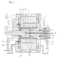
Fig. 1 is a sectional view showing a motor to which a cooling structure according to a first embodiment of the present invention is applied; -
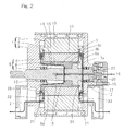
Fig. 2 is a sectional view showing a motor to which a cooling structure according to a second embodiment of the present invention is applied; and -
Fig. 3 is a sectional view showing an important portion of the motor which is a modified form of the present invention. - A first embodiment of the present invention will be described in detail with particular reference to
Fig. 1 . The motor, to which this cooling structure is applied, is made up of a stator 1 and a rotor 5 and is a motor of a radial gap type, in which a radially spacedgap portion 10 is provided intermediate between astator core 2 of the stator 1 and arotor core 6 of the rotor 5. - The stator 1 includes the
stator core 2 referred to above and having an annular shape, astator coil 3 arranged on opposite axial sides of thestator core 2, and a stator housing 4 accommodating thestator core 2 and thestator coil 3. Thestator core 2 is specifically of a type, in which a stator coil is wound around each of a plurality of cores arranged in an annular configuration, and is fixed to an inner peripheral surface of the stator housing 4. A space delimited by and among thestator core 2 and thestator coil 3 and the stator housing 4 is molded by amolding material 11. - The rotor 5 is of a type arranged on an inner peripheral side of the
stator core 2 and includes therotor core 6 of an annular configuration in the form of a permanent magnet, arotor drive shaft 7 positioned at a center of the rotor 5, and atubular rotor spindle 8 interposed between therotor core 6 and therotor drive shaft 7 to couple therotor core 6 and therotor drive shaft 7 so as to rotate together. Therotor drive shaft 7 is supported bybearings 12 for rotation relative to the stator housing 4. Therotor drive shaft 7 and therotor spindle 8 are fixed to each other by means of, for example, press-fitting and, similarly, therotor spindle 8 and therotor core 6 are fixed to each other by means of press-fitting. - The
rotor drive shaft 7 has alarge diameter portion 7a defined at an axially intermediate portion thereof, and aright end portion 8a and anintermediate portion 8b of therotor spindle 8 are held in contact with an outer periphery of thelarge diameter portion 7a of therotor drive shaft 7 and a portion of an outer periphery of therotor drive shaft 7 that lies axially leftwards of thelarge diameter portion 7a, respectively. Anon-contact portion 8c of therotor spindle 8, which is not held in contact with therotor drive shaft 7 has an innerperipheral surface 13 tapered outwardly towards an end portion side (leftwards as viewed in the drawing in the illustrated embodiment) to represent a large diameter. Acooling space 15 is defined between the tapered innerperipheral surface 13 and an outerperipheral surface 14 of therotor drive shaft 7. Thecooling space 15 referred to above has its end portion opening outwardly. A further tip side of the rotor spindlenon-contact portion 8c is rendered to be acollar portion 8d lying along an end face of therotor core 6. - For the purpose of cooling the inside of the motor, an
oil feed passage 17 is provided within therotor drive shaft 7 for the flow of acooling oil 16 therethrough. Thisoil feed passage 17 have coolingoil discharge ports 18 which are formed in the outerperipheral surface 14 of therotor drive shaft 7 confronting thecooling space 15. In the case of the illustrated embodiment, two axial portions of the outerperipheral surface 14 of therotor drive shaft 7 are formed each with two coolingoil discharge ports 18. The coolingoil discharge ports 18 at the two portions in the same axial position are arranged at respective positions spaced 180° in phase from each other. Also, the coolingoil discharge ports 18 at the two portions in the different axial positions are held in respective phases different from each other. It is, however, to be noted that the coolingoil discharge port 18 may be formed at three or more axial locations on the outer peripheral surface of therotor drive shaft 7. - The
cooling oil 16 is fed under pressure from the outside into theoil feed passage 17. An oil supply tube (not shown), through which thecooling oil 16 is supplied under pressure, is fluid coupled with acap 20 fixed to the stator housing 4 by means of abolt 19. Anoil seal 21 for sealing the interior of the motor from the outside is interposed between thecap 20 and therotor drive shaft 7. - An open end of the
cooling space 15 is fluidly connected with anoil discharge passage 23 for discharging thecooling oil 16 to the outside. Theoil discharge passage 23 extends axially outwardly from thecollar portion 8d of therotor spindle 8 towards anannular groove 4a defined in the stator housing 4 and then towards the outside of the motor by way of anoil tank 24. A side wall portion of the stator housing 4, which confronts an end face of therotor core 6, is provided with anoil guide ring 25 having its tip held in proximity to the end face of therotor core 6. This oil guide ring 26 is operable to guide the coolingoil 16 flowing radially outwardly along the end face of therotor core 6, towards theoil discharge passage 23 to thereby avoid an undesirable flow of the coolingoil 16 into thegap portion 10 delimited between thestator core 2 and therotor core 6. - As shown in
Fig. 3 , by providing ahamper portion 40 in the form of grooves of, for example, an annular shape is provided in the tapered innerperipheral surface 13 of therotor spindle 8, the smooth flow of the coolingoil 16 can be hampered so that the coolingcoil 16 can be conducted towards the entire surface of the tapered innerperipheral surface 13. By so doing, an effect to remove the heat evolved in the rotor 5 can be increased. For thehamper portion 40, the grooves may be superseded with a weir or weirs that protrude from the tapered innerperipheral surface 13 into the coolingspace 15. - According to the foregoing cooling structure for the motor, the cooling
oil 16 supplied from the outside can be discharged from the coolingoil discharge ports 18, open at the outer peripheral surface of therotor drive shaft 7, into the coolingspace 15 after having flowed through theoil feed passage 17 defined inside therotor drive shaft 7. The coolingoil 16 so discharged subsequently impinges upon the tapered innerperipheral surface 13 and, then, flows towards a large diametric side in the form as scattered over the entire surface of the tapered innerperipheral surface 13 under the influence of a centrifugal force developed as a result of rotation of therotor spindle 8. At this time, the heat evolved in the rotor 5 is efficiently removed. - The cooling
oil 16, which has flowed towards one of opposite ends of the tapered innerperipheral surface 13, which is adjacent to the large diametric side thereof, is pooled within theoil tank 24 after having flowed through theoil discharge passage 23, and an excessive fraction of the coolingoil 16 within theoil tank 24 is discharged to the outside of the motor. Since theoil guide ring 25 is provided, the coolingoil 16 does not flow into thegap portion 10 delimited between thestator core 2 and therotor core 6 and, therefore, motor loss may be avoided, which would otherwise results from the stirring resistance of the coolingoil 16 accumulated within thegap portion 10. -
Fig. 2 illustrates a second embodiment of the present invention. While the cooling structure according to the previously described first embodiment has been designed with emphasis placed not only on the efficient removal of the heat evolved in the rotor 5, but also on avoidance of the motor loss resulting from the stirring resistance of the coolingoil 16 accumulated within thegap portion 10, the cooling structure according to this second embodiment is designed with emphasis placed on the cooling effect on thestator coil 2. More specifically, agap 31 is defined between an inner side wall portion of the stator housing 4 and the respective end faces of therotor spindle 8 and therotor core 6 so as to form anoil discharge passage 32 through which the coolingoil 16 then flowing from an end portion of the coolingspace 15 in a radially outward direction can flow into theoil tank 24 through thestator coil 3. Thestator coil 3 is of a non-molded structure, in which the coolingoil 16 may contact the coil winding directly. In other words, thestator coil 3 is of a type not molded, and with the coil winding exposed. Also, anoil guide ring 33 for guiding the coolingoil 16 flowing through thegap 31, to fall onto therotor core 6, is provided in the inner side wall portion of the stator housing 4. - The
oil discharge passage 32 referred to above are defined on respective left and right sides of thestator core 2, therotor core 6 and therotor spindle 8. Accordingly, unlike that in the previously described first embodiment, a coolingoil discharge port 34, from which the coolingoil 16 within theoil feed passage 17 can be discharged into theoil discharge passage 32 on the right side, is provided in the outer peripheral surface of therotor drive shaft 7. - Even with the cooling structure according to the second embodiment of the present invention, in a manner similar to that exhibited by the cooling structure according to the first embodiment, the cooling
oil 16 can be discharged from the coolingoil discharge ports 18 into the coolingspace 15 and the heat evolved in the rotor 5 can be efficiently removed while the coolingoil 16 discharged into the coolingspace 15 flows along the tapered innerperipheral surface 13 and the end face of therotor spindle 8. In addition, since in the case of this second embodiment, the coolingliquid 16 flowing through thegap 31 is guided by theoil guide ring 33 so as to fall on therotor core 6, therotor core 6 can be cooled directly and the heat evolved in the rotor 5 can be removed further efficiently. Moreover, since the coolingoil 16 flows in contact with the coil winding of thestator coil 3, which is of the non-molded structure, heat evolved in thestator coil 3 can also be removed. In view of those, the cooling structure according to this embodiment may have a high effect of cooling the inside of the motor. - It is, however, to be noted that since the cooling
oil 16 flows into thegap portion 10 delimited between thestator core 2 and therotor core 6, the motor loss, which would result from the stirring resistance of the coolingoil 16 accumulated within thegap portion 10, cannot be avoided. - Although the motor, to which the cooling structure according to any one of the foregoing embodiments of the present invention has been adopted, has an excellent effect of cooling the interior of the motor, the respective motors designed according to those embodiments have their own advantages. Accordingly, depending on the specification and the application of the motor, one of the cooling structures according to the associated embodiments has to be selected.
- Although the present invention has been fully described in connection with the embodiments thereof with reference to the accompanying drawings which are used only for the purpose of illustration, those skilled in the art will readily conceive numerous changes and modifications within the framework of obviousness upon the reading of the specification herein presented of the present invention. Accordingly, such changes and modifications are, unless they depart from the scope of the present invention as delivered from the claims annexed hereto, to be construed as included therein.
- Reference Numerals
- 1:
- Stator
- 2:
- Stator core
- 3:
- Stator coil
- 4.
- Stator housing
- 5:
- Rotor
- 6:
- Rotor core
- 7:
- Rotor drive shaft
- 8:
- Rotor spindle
- 10:
- Gap portion
- 11:
- Molding material
- 13:
- Inner peripheral surface of the rotor spindle
- 14:
- Outer peripheral surface of the rotor drive shaft
- 15:
- Cooling space
- 16:
- Cooling oil
- 17:
- Oil feed passage
- 18, 34:
- Cooling oil discharge port
- 23, 32:
- Oil discharge passage
- 25, 33:
- Oil guide ring
- 31:
- Gap
- 40:
- Inhibitor
Claims (8)
- A cooling structure of a motor, which motor comprises a stator having a stator coil and a stator core arranged or formed in an annular shape, and a rotor positioned on an inner peripheral side of the stator core and rotatable relative to the stator, the rotor having a rotor drive shaft, positioned at a center, a tubular rotor spindle provided on an outer periphery of the rotor drive shaft and a rotor core fitted to an outer periphery of a rotor spindle,
wherein an outer peripheral surface of the rotor drive shaft and an inner peripheral surface of the rotor spindle cooperatively define a cooling space therebetween having an end portion opening,
the rotor spindle having a tapered inner peripheral surface so as to have a larger diameter at the end portion, and
the rotor drive shaft having an oil feed passage for a cooling oil defined therein, a cooling oil discharge port of such oil feed passage being defined in a portion of the outer peripheral surface of the rotor drive shaft confronting the cooling space. - The cooling structure for the motor as claimed in claim 1, further comprising a hamper portion provided within the cooling space for hampering a smooth flow of the cooling oil flowing along the inner peripheral surface of the rotor spindle.
- The cooling structure for the motor as claimed in claim 1, wherein the rotor drive shaft is formed with a plurality of the cooling oil discharge port of the oil feed passage on an outer peripheral surface thereof.
- The cooling structure for the motor as claimed in claim 1, further comprising a stator housing for accommodating therein the stator coil and the stator core, the stator housing including an oil discharge passage for discharging the cooling oil therefrom and an oil guide ring for guiding the cooling oil flowing radially outwardly along an end face of the rotor spindle or the rotor core, towards the oil discharge passage, provided in a side wall portion of the stator housing confronting the end face of the rotor spindle or the rotor core and in proximity to such end face of the rotor spindle or the rotor core.
- The cooling structure for the motor as claimed in claim 1, further comprising a stator housing for accommodating therein the stator coil and the stator core, wherein a gap for enabling the cooling oil flowing from an end portion of the cooling space towards an outer diametric side, to reach the stator coil is provided between a side wall portion of the stator housing, confronting respective end faces of the rotor spindle and the rotor core, and the respective end faces of the rotor spindle and the rotor core.
- The cooling structure for the motor as claimed in claim 5, wherein the stator coil is of a non-molded structure in which the cooling oil contacts a coil winding directly.
- The cooling structure for the motor as claimed in claim 1, further comprising a stator housing for accommodating therein the stator coil and the stator core, the stator housing including an oil guide ring for guiding the cooling oil flowing from an end portion of the cooling space towards an outer diametric side, so as to fall on the rotor spindle or the rotor core is provided in a side wall portion of the stator housing confronting respective end faces of the rotor spindle and the rotor core.
- A motor having a cooling structure as defined in claim 1.
Applications Claiming Priority (2)
| Application Number | Priority Date | Filing Date | Title |
|---|---|---|---|
| JP2008144134A JP2009291056A (en) | 2008-06-02 | 2008-06-02 | Motor cooling structure |
| PCT/JP2009/002307 WO2009147798A1 (en) | 2008-06-02 | 2009-05-26 | Cooling structure of motor |
Publications (1)
| Publication Number | Publication Date |
|---|---|
| EP2299564A1 true EP2299564A1 (en) | 2011-03-23 |
Family
ID=41397884
Family Applications (1)
| Application Number | Title | Priority Date | Filing Date |
|---|---|---|---|
| EP09758065A Withdrawn EP2299564A1 (en) | 2008-06-02 | 2009-05-26 | Cooling structure of motor |
Country Status (4)
| Country | Link |
|---|---|
| US (1) | US20110074233A1 (en) |
| EP (1) | EP2299564A1 (en) |
| JP (1) | JP2009291056A (en) |
| WO (1) | WO2009147798A1 (en) |
Cited By (4)
| Publication number | Priority date | Publication date | Assignee | Title |
|---|---|---|---|---|
| WO2013000704A3 (en) * | 2011-06-29 | 2013-08-15 | Robert Bosch Gmbh | Rotor armature for an electric motor |
| EP3618241A1 (en) * | 2018-08-30 | 2020-03-04 | General Electric Company | Electric machine with rotor coolant and lubrication distribution system, and systems and methods of cooling and lubricating an electric machine |
| CN111033969A (en) * | 2017-08-25 | 2020-04-17 | 日本电产株式会社 | drive |
| CN112467912A (en) * | 2020-11-18 | 2021-03-09 | 珠海格力电器股份有限公司 | Oil cooling mechanism for motor, oil cooling system and motor |
Families Citing this family (25)
| Publication number | Priority date | Publication date | Assignee | Title |
|---|---|---|---|---|
| JP5097743B2 (en) * | 2009-04-09 | 2012-12-12 | 本田技研工業株式会社 | Electric motor |
| DE112010004773T5 (en) * | 2010-03-24 | 2012-10-18 | Aisin Aw Co. Ltd. | Rotor for a rotating electrical machine |
| JP5387476B2 (en) * | 2010-03-25 | 2014-01-15 | トヨタ自動車株式会社 | Motor cooling device |
| SE534838C2 (en) * | 2010-05-21 | 2012-01-17 | Bae Systems Haegglunds Ab | Electric motor cooling device |
| EP2680410A4 (en) * | 2011-02-21 | 2018-03-07 | Hitachi, Ltd. | Motor |
| JP5188593B2 (en) * | 2011-03-31 | 2013-04-24 | 株式会社小松製作所 | Generator motor cooling structure and generator motor |
| JP5188592B2 (en) * | 2011-03-31 | 2013-04-24 | 株式会社小松製作所 | Generator motor cooling structure and generator motor |
| JP5663451B2 (en) * | 2011-10-19 | 2015-02-04 | 株式会社安川電機 | Stator and rotating electric machine |
| JP5715299B2 (en) * | 2012-03-30 | 2015-05-07 | 本田技研工業株式会社 | Rotating electric machine |
| US9657747B2 (en) | 2012-09-06 | 2017-05-23 | Carrier Corporation | Motor rotor and air gap cooling |
| SE537090C2 (en) * | 2012-11-07 | 2015-01-07 | BAE Systems Hägglunds Aktiebolag | Method and apparatus for liquid cooling an electric motor |
| JP6119962B2 (en) * | 2012-11-15 | 2017-04-26 | 株式会社豊田自動織機 | Electric compressor |
| JP6424645B2 (en) * | 2015-01-22 | 2018-11-21 | 株式会社デンソー | Electric rotating machine |
| JP6145120B2 (en) * | 2015-02-13 | 2017-06-07 | ファナック株式会社 | Rotor having flow path for cooling fluid and electric motor including the rotor |
| US20190010913A1 (en) * | 2015-07-14 | 2019-01-10 | HeliosAltas Corp. | Water wheel generator assembly |
| CN112217305A (en) * | 2020-11-04 | 2021-01-12 | 湘潭大学 | Internal circulation type cooling structure of large-scale high-speed permanent magnet motor rotor spindle |
| JP2022107336A (en) * | 2021-01-08 | 2022-07-21 | トヨタ自動車株式会社 | Motor magnet oil-cooled structure and motor |
| CN112803642B (en) * | 2021-01-21 | 2025-07-29 | 珠海格力电器股份有限公司 | Motor rotor and magnetic suspension motor |
| FR3125178A1 (en) * | 2021-07-12 | 2023-01-13 | Nidec Psa Emotors | Rotating electric machine |
| CN113410928A (en) * | 2021-07-14 | 2021-09-17 | 苏州启承动能科技有限公司 | Internal oil cooling high-speed motor |
| DE112023005702T5 (en) | 2023-01-30 | 2025-11-13 | Gkn Automotive Limited | Electric machine with oil cooling |
| CN116207924B (en) * | 2023-02-13 | 2023-12-19 | 苏州朗高电机有限公司 | Oil cooling driving motor applied to heavy truck |
| CN116961284A (en) * | 2023-06-21 | 2023-10-27 | 智新科技股份有限公司 | Oil-cooled hollow shaft structure |
| CN118282131A (en) * | 2024-05-31 | 2024-07-02 | 陕西汉德车桥有限公司 | Cooling structure of driving motor and driving motor |
| CN118646210B (en) * | 2024-08-09 | 2024-11-26 | 浙江欣立电器科技有限公司 | A special jet spindle servo motor for textile equipment |
Family Cites Families (15)
| Publication number | Priority date | Publication date | Assignee | Title |
|---|---|---|---|---|
| JPH09154258A (en) | 1995-11-29 | 1997-06-10 | Mitsubishi Heavy Ind Ltd | Forced oil-cooled motor or generator cooling structure |
| JPH09182374A (en) * | 1995-12-21 | 1997-07-11 | Aisin Aw Co Ltd | Motor cooling circuit |
| KR100297336B1 (en) * | 1999-01-29 | 2001-10-22 | 가이 가즈오 | Eccentric commutator, manufacturing method thereof and flat coreless vibrator motor using the eccentric commutator |
| JP3967624B2 (en) * | 2002-04-26 | 2007-08-29 | 株式会社日本自動車部品総合研究所 | Electric motor |
| JP2004080937A (en) * | 2002-08-20 | 2004-03-11 | Honda Motor Co Ltd | Generator motor device |
| JP3891348B2 (en) * | 2002-12-27 | 2007-03-14 | アイシン・エィ・ダブリュ株式会社 | Electric drive |
| JP4136736B2 (en) * | 2003-03-14 | 2008-08-20 | トヨタ自動車株式会社 | Rotating electric machine and manufacturing method thereof |
| JP2005073351A (en) * | 2003-08-22 | 2005-03-17 | Toyota Motor Corp | Cooling structure of rotating electric machine |
| JP4301060B2 (en) * | 2004-04-05 | 2009-07-22 | 日産自動車株式会社 | Rotor structure of axial gap motor |
| JP4664737B2 (en) * | 2004-07-30 | 2011-04-06 | 本田技研工業株式会社 | Cooling structure of rotating electric machine |
| JP4567491B2 (en) * | 2005-03-08 | 2010-10-20 | 本田技研工業株式会社 | Wheel drive device for vehicle |
| JP4550631B2 (en) * | 2005-03-11 | 2010-09-22 | 本田技研工業株式会社 | Wheel drive device for vehicle |
| JP2006300101A (en) * | 2005-04-15 | 2006-11-02 | Toyota Motor Corp | Lubricator for rotating electrical machine |
| JP4858680B2 (en) * | 2005-12-07 | 2012-01-18 | シンフォニアテクノロジー株式会社 | Coil cooling mechanism |
| JP5259147B2 (en) | 2006-11-15 | 2013-08-07 | エスケー化研株式会社 | Aqueous resin composition |
-
2008
- 2008-06-02 JP JP2008144134A patent/JP2009291056A/en not_active Withdrawn
-
2009
- 2009-05-26 US US12/736,990 patent/US20110074233A1/en not_active Abandoned
- 2009-05-26 EP EP09758065A patent/EP2299564A1/en not_active Withdrawn
- 2009-05-26 WO PCT/JP2009/002307 patent/WO2009147798A1/en not_active Ceased
Non-Patent Citations (1)
| Title |
|---|
| See references of WO2009147798A1 * |
Cited By (8)
| Publication number | Priority date | Publication date | Assignee | Title |
|---|---|---|---|---|
| WO2013000704A3 (en) * | 2011-06-29 | 2013-08-15 | Robert Bosch Gmbh | Rotor armature for an electric motor |
| CN103620919A (en) * | 2011-06-29 | 2014-03-05 | 罗伯特·博世有限公司 | Rotor armature for an electric motor |
| CN111033969A (en) * | 2017-08-25 | 2020-04-17 | 日本电产株式会社 | drive |
| EP3618241A1 (en) * | 2018-08-30 | 2020-03-04 | General Electric Company | Electric machine with rotor coolant and lubrication distribution system, and systems and methods of cooling and lubricating an electric machine |
| CN110875660A (en) * | 2018-08-30 | 2020-03-10 | 通用电气公司 | Electric machine with rotor coolant and lubrication distribution system, and system and method for cooling and lubricating electric machine |
| US11146133B2 (en) | 2018-08-30 | 2021-10-12 | General Electric Company | Electric machine with rotor coolant and lubrication distribution system, and systems and methods of cooling and lubricating an electric machine |
| CN110875660B (en) * | 2018-08-30 | 2022-01-25 | 通用电气公司 | Electric machine with rotor coolant and lubrication distribution system, and system and method for cooling and lubricating an electric machine |
| CN112467912A (en) * | 2020-11-18 | 2021-03-09 | 珠海格力电器股份有限公司 | Oil cooling mechanism for motor, oil cooling system and motor |
Also Published As
| Publication number | Publication date |
|---|---|
| WO2009147798A1 (en) | 2009-12-10 |
| US20110074233A1 (en) | 2011-03-31 |
| JP2009291056A (en) | 2009-12-10 |
Similar Documents
| Publication | Publication Date | Title |
|---|---|---|
| US20110074233A1 (en) | Cooling structure of motor | |
| US8686606B2 (en) | Cooling device | |
| CN104285361B (en) | Electrical machine having a rotor for cooling the electrical machine | |
| US9960649B2 (en) | Rotating electric machine | |
| US9793783B2 (en) | Rotor of rotary electric machine | |
| US9819247B2 (en) | Cooling jacket for an electric motor or generator having coolant inlet and outlets with opposite flow direction streams | |
| US8614528B2 (en) | Electric machine having radial dividers for guiding cooling air | |
| US10001139B2 (en) | Electric coolant pump | |
| CN111416456B (en) | Liquid-cooled rotor for an electric machine | |
| EP3054564A1 (en) | Rotary electric machine | |
| EP3058643B1 (en) | Electric motor | |
| EP2330719A1 (en) | Vehicle drive motor | |
| CN107888024B (en) | Cooling system and motor | |
| KR20130114147A (en) | Electric machine cooling system and method | |
| JP2015104214A (en) | Rotary electric machine | |
| CN113394937B (en) | Axial flux electric machine including a system for circulating a coolant through an air gap | |
| US20130342052A1 (en) | Electric machine with circumferential rotor and housing fins | |
| KR20140008518A (en) | Electric machine cooling system and method | |
| EP3764524B1 (en) | Dynamo-electric machine | |
| CN109075636A (en) | The cooling of mixed rotor module | |
| US20120013206A1 (en) | Cooling System and Method for an Electric Machine Module | |
| JP2013021811A (en) | Rotor of rotary electric machine | |
| JP2013258889A (en) | Induction motor | |
| US10601272B2 (en) | Rotor for an electrical machine, electrical machine, in particular an asynchronous machine for a motor vehicle, and motor vehicle | |
| US9257881B2 (en) | Rotating electric machine |
Legal Events
| Date | Code | Title | Description |
|---|---|---|---|
| PUAI | Public reference made under article 153(3) epc to a published international application that has entered the european phase |
Free format text: ORIGINAL CODE: 0009012 |
|
| 17P | Request for examination filed |
Effective date: 20110103 |
|
| AK | Designated contracting states |
Kind code of ref document: A1 Designated state(s): AT BE BG CH CY CZ DE DK EE ES FI FR GB GR HR HU IE IS IT LI LT LU LV MC MK MT NL NO PL PT RO SE SI SK TR |
|
| AX | Request for extension of the european patent |
Extension state: AL BA RS |
|
| DAX | Request for extension of the european patent (deleted) | ||
| STAA | Information on the status of an ep patent application or granted ep patent |
Free format text: STATUS: THE APPLICATION IS DEEMED TO BE WITHDRAWN |
|
| 18D | Application deemed to be withdrawn |
Effective date: 20131203 |