EP2299514A1 - Secondary battery - Google Patents
Secondary battery Download PDFInfo
- Publication number
- EP2299514A1 EP2299514A1 EP08800949A EP08800949A EP2299514A1 EP 2299514 A1 EP2299514 A1 EP 2299514A1 EP 08800949 A EP08800949 A EP 08800949A EP 08800949 A EP08800949 A EP 08800949A EP 2299514 A1 EP2299514 A1 EP 2299514A1
- Authority
- EP
- European Patent Office
- Prior art keywords
- tabs
- pad
- secondary battery
- out device
- conductive layer
- Prior art date
- Legal status (The legal status is an assumption and is not a legal conclusion. Google has not performed a legal analysis and makes no representation as to the accuracy of the status listed.)
- Withdrawn
Links
- 239000011148 porous material Substances 0.000 claims description 29
- 238000003466 welding Methods 0.000 claims description 17
- 238000000608 laser ablation Methods 0.000 claims description 3
- 238000004519 manufacturing process Methods 0.000 description 4
- XEEYBQQBJWHFJM-UHFFFAOYSA-N Iron Chemical compound [Fe] XEEYBQQBJWHFJM-UHFFFAOYSA-N 0.000 description 2
- PXHVJJICTQNCMI-UHFFFAOYSA-N Nickel Chemical compound [Ni] PXHVJJICTQNCMI-UHFFFAOYSA-N 0.000 description 2
- 230000007423 decrease Effects 0.000 description 2
- 239000008151 electrolyte solution Substances 0.000 description 2
- 239000012528 membrane Substances 0.000 description 2
- HBBGRARXTFLTSG-UHFFFAOYSA-N Lithium ion Chemical compound [Li+] HBBGRARXTFLTSG-UHFFFAOYSA-N 0.000 description 1
- XAGFODPZIPBFFR-UHFFFAOYSA-N aluminium Chemical compound [Al] XAGFODPZIPBFFR-UHFFFAOYSA-N 0.000 description 1
- 230000009286 beneficial effect Effects 0.000 description 1
- 238000010586 diagram Methods 0.000 description 1
- 238000007599 discharging Methods 0.000 description 1
- 230000000694 effects Effects 0.000 description 1
- 238000004146 energy storage Methods 0.000 description 1
- 238000005516 engineering process Methods 0.000 description 1
- 238000004880 explosion Methods 0.000 description 1
- 239000011888 foil Substances 0.000 description 1
- 238000010438 heat treatment Methods 0.000 description 1
- 229910052742 iron Inorganic materials 0.000 description 1
- 229910001416 lithium ion Inorganic materials 0.000 description 1
- 229910052751 metal Inorganic materials 0.000 description 1
- 239000002184 metal Substances 0.000 description 1
- 239000007769 metal material Substances 0.000 description 1
- 238000012986 modification Methods 0.000 description 1
- 230000004048 modification Effects 0.000 description 1
- 229910052759 nickel Inorganic materials 0.000 description 1
- 238000013021 overheating Methods 0.000 description 1
- 239000000243 solution Substances 0.000 description 1
- 229910001220 stainless steel Inorganic materials 0.000 description 1
- 239000010935 stainless steel Substances 0.000 description 1
- 210000000352 storage cell Anatomy 0.000 description 1
- 239000010409 thin film Substances 0.000 description 1
Images


Classifications
-
- H—ELECTRICITY
- H01—ELECTRIC ELEMENTS
- H01M—PROCESSES OR MEANS, e.g. BATTERIES, FOR THE DIRECT CONVERSION OF CHEMICAL ENERGY INTO ELECTRICAL ENERGY
- H01M50/00—Constructional details or processes of manufacture of the non-active parts of electrochemical cells other than fuel cells, e.g. hybrid cells
- H01M50/10—Primary casings; Jackets or wrappings
- H01M50/147—Lids or covers
-
- H—ELECTRICITY
- H01—ELECTRIC ELEMENTS
- H01M—PROCESSES OR MEANS, e.g. BATTERIES, FOR THE DIRECT CONVERSION OF CHEMICAL ENERGY INTO ELECTRICAL ENERGY
- H01M10/00—Secondary cells; Manufacture thereof
- H01M10/04—Construction or manufacture in general
- H01M10/0431—Cells with wound or folded electrodes
-
- H—ELECTRICITY
- H01—ELECTRIC ELEMENTS
- H01M—PROCESSES OR MEANS, e.g. BATTERIES, FOR THE DIRECT CONVERSION OF CHEMICAL ENERGY INTO ELECTRICAL ENERGY
- H01M50/00—Constructional details or processes of manufacture of the non-active parts of electrochemical cells other than fuel cells, e.g. hybrid cells
- H01M50/50—Current conducting connections for cells or batteries
- H01M50/528—Fixed electrical connections, i.e. not intended for disconnection
-
- H—ELECTRICITY
- H01—ELECTRIC ELEMENTS
- H01M—PROCESSES OR MEANS, e.g. BATTERIES, FOR THE DIRECT CONVERSION OF CHEMICAL ENERGY INTO ELECTRICAL ENERGY
- H01M50/00—Constructional details or processes of manufacture of the non-active parts of electrochemical cells other than fuel cells, e.g. hybrid cells
- H01M50/50—Current conducting connections for cells or batteries
- H01M50/531—Electrode connections inside a battery casing
- H01M50/536—Electrode connections inside a battery casing characterised by the method of fixing the leads to the electrodes, e.g. by welding
-
- Y—GENERAL TAGGING OF NEW TECHNOLOGICAL DEVELOPMENTS; GENERAL TAGGING OF CROSS-SECTIONAL TECHNOLOGIES SPANNING OVER SEVERAL SECTIONS OF THE IPC; TECHNICAL SUBJECTS COVERED BY FORMER USPC CROSS-REFERENCE ART COLLECTIONS [XRACs] AND DIGESTS
- Y02—TECHNOLOGIES OR APPLICATIONS FOR MITIGATION OR ADAPTATION AGAINST CLIMATE CHANGE
- Y02E—REDUCTION OF GREENHOUSE GAS [GHG] EMISSIONS, RELATED TO ENERGY GENERATION, TRANSMISSION OR DISTRIBUTION
- Y02E60/00—Enabling technologies; Technologies with a potential or indirect contribution to GHG emissions mitigation
- Y02E60/10—Energy storage using batteries
Definitions
- the present invention relates to a secondary battery, in particular, to a connecting structure between tabs and a cover plate of the secondary battery.
- a lithium-ion secondary battery is composed of a negative polar plate, a positive polar plate, an electrolytic solution and a membrane between the positive and negative polar plates for preventing a short circuit.
- the positive polar plate and the negative polar plate are formed as a thin plate or a foil.
- the electrical polar plates and the membrane therebetween are orderly stacked or helically wound so as to form a core, which is in turn embedded into a battery container made of a stainless steel, a nickel plated iron, an aluminum metal or a stacked flexible package thin film. Then, after electrolytic solution is injected into the battery container, the battery container is sealed and the battery is formed.
- the core is electrically connected to external components by a connection between tabs connected to the polar plates and a pole or a cover plate.
- the tabs are welded at the pole of the cover plate.
- a heavy current is discharged, for example, in a hybrid electrical vehicle (HEV) or an electrical vehicle (EV)
- HEV hybrid electrical vehicle
- EV electrical vehicle
- a connection at places such as the tabs and the pole is broken or inactive, a serious heating may occur, resulting in an overheating, even a failure, of the battery.
- the safety and cycle life of the battery may be influenced.
- the welding position may not be controlled accurately when a plurality of tabs are connected to the pole, which is unfavorable for the control of technology and quality.
- the present invention aims to overcome the above-mentioned disadvantages.
- the present invention provides a secondary battery, which improves the connection between a plurality of tabs and the pole, reduces the internal resistance of the battery and decreases the heat produced by the battery.
- the secondary battery comprises a core and a cover plate, wherein tabs are protruded from an end of the core, the tabs comprises positive tabs and negative tabs.
- the secondary battery is characterized in that a tab lead-out device is provided at the end of the core, the tab lead-out device comprises an insulating layer adjacent to the end of the core and a conductive layer away from the end of the core, the tabs are electrically connected to the conductive layer, and the conductive layer is electrically connected to the cover plate.
- the tab lead-out device is of a structure that the insulating layer and conductive layer are formed integratedly.
- the tab lead-out device is in a shape of a disk.
- Pores are disposed in the tab lead-out device, the tabs passes through the pores and are then electrically connected to the conductive layer.
- the pores in the tab lead-out device are in a shape of sectors.
- the tabs protrude from an outer edge of the tab lead-out device and are then electrically connected to the conductive layer.
- the tab lead-out device comprises an insulating pad and a first pad.
- the insulating pad forms the insulating layer
- the first pad forms the conductive layer.
- the insulating pad and the first pad are in a shape of a disk.
- the insulating pad is provided with pores
- the first pad is provided with pores.
- the tabs passes through the pores in the insulating pad and the pores in the first pad and are then electrically connected to the first pad.
- the pores in the insulating pad and the pores in the first pad are in a shape of sectors.
- the tabs protrude from outer edges of the insulating pad and the first pad and are then electrically connected to the first pad.
- the secondary battery further comprises a connector and a second pad stacked between the conductive layer of the tab lead-out device and the cover plate.
- the tabs are compacted between the second pad and the conductive layer of the tab lead-out device by the connector.
- the second pad is provided with pores at positions corresponding to the tabs.
- the connector is a bolt connector.
- a screw of the bolt connector is fixedly disposed on the conductive layer of the tab lead-out device.
- the second pad is compacted on the conductive layer of the tab lead-out device by the nut.
- the conductive layer of the tab lead-out device is electrically connected to the cover plate by the connector.
- a pole is disposed on the cover plate.
- the connector is electrically connected to the pole on the cover plate.
- connection between the tabs and the conductive layer of the tab lead-out device is a welding connection.
- connection between the tabs and the conductive layer of the tab lead-out device is a laser ablation welding connection.
- the positive tabs and negative tabs comprise a plurality of positive tabs and a plurality of negative tabs, respectively.
- the plurality of positive tabs are located at one end of the core, the plurality of negative tabs are located at the other end of the core.
- connection between the plurality of tabs and the conductive layer of the tab lead-out device is a welding connection.
- the plurality of tabs are welded to the conductive layer of the tab lead-out device at corresponding positions, respectively.
- a tab lead-out device is provided, so that the tabs are electrically connected to the tab lead-out device fixedly and thus the connecting points of the tabs are reliable and stable.
- Pores are disposed at fixed positions in the tab lead-out device. This ensures that the connecting positions of the tabs, for example, welding positions, are accurate and consistent and the welding can be performed conveniently, which are beneficial to improve the production efficiency. In particularly, for a core with a plurality of tabs, it is ensured that the welding position of each tab is accurate.
- a second pad is provided. By the mechanical compact of the second pad, it is ensured that the tabs of the core are reliably connected to the pole. The effective contact area between the tabs and the pole is also increased.
- a laser ablation welding is applied between the tabs and the tab lead-out device, which further improves the conductive efficiency, ensures the battery performance when discharging, reduces the internal resistance of the battery, decreases the heat produced by battery and improves the battery cycle life.
- the tab lead-out device, the second pad and the cover plate are tightly contacted, which ensures the stable fixation of the core.
- the connecting structure between the tabs and the pole of the battery is simple and convenient to be assembled. The manufacture is economical, and it is easy for the line production and convenient for the industrialized production.
- the present invention is very suitable for the cylinder battery with multiple tabs and a large size.
- the core may be fixed efficiently, the vibration resistance and the compact resistance of battery are improved, and then the safety performance of the battery is improved. So, it is suitable for the battery of hybrid electrical vehicle and electrical vehicle, and it also can be used for the large-sized energy storage cell.
- Figure 1 is a structural schematic diagram of a first embodiment of the present invention
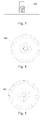
- Figure 2 is a structural view of the insulating pad in Figure 1 ;
- Figure 3 is a structural view of the first pad in Figure 1 ;
- Figure 4 is a top view of Figure 3 ;
- Figure 5 is a structural view of the second pad in Figure 1 ;
- Figure 6 is a structural view of the cover plate in Figure 1 ;
- Figure 7 is a structural view of the tab lead-out device of a second embodiment of the present invention.
- Figure 8 is a structural view of the tab lead-out device of a third embodiment of the present invention.
- a secondary battery as shown in Figure 1 , comprises a cover plate 1, a connector, a tab lead-out device, a second pad 3 and a core 7.
- the tab lead-out device includes an insulating pad 6 and a first pad 5.
- the insulting pad 6 constitutes an insulting layer.
- the first pad 5 constitutes a conductive layer.
- the connector includes a nut 2 and a screw 502 fixed to the first pad.
- Battery polar plates are wound to form the core 7 in a cylinder shape.
- a plurality of tabs 4 are protruded from each end of the core 7.
- the tabs at one end of the core 7 are positive tabs, and those at the other end are negative tabs.
- the tabs at both ends are connected to the cover plate via connections having a same structure.
- the insulting pad 6 is circular, and is placed at an end of the core 7. As shown in Figure 2 , pores 601 in the form of discontinuous sectors are disposed at the insulting pad 6.
- the first pad 5 is stacked on the insulting pad 6.
- pores 501 in the form of discontinuous sectors are disposed in the first pad 5, and a screw 502 having screw threads is further disposed at the center of the first pad 5.
- An upper end of the screw 502 passes through a center hole of the insulting pad 6.
- a lower end of the screw 502 passes through a center hole of the second pad 3.
- the second pad 3 is fastened with the first pad by a nut 2.
- pores 301 are disposed in the second pad 3.
- the cover plate 1 as shown in Figure 6 is placed on the second pad 3.
- a pole 104 is provided on the cover plate 1.
- a center hole 101 is disposed at the center of the pole 104.
- the cover plate 1 further comprises an infusing hole 102 and an explosion proof hole 103.
- the first pad 5, the second pad 6, the tabs 4, the cover plate 1, the pole 104 are made of conductive metal material.
- the cover plate 1 is insulated from the pole 4.
- the tabs 4 pass through the pores 601 of the insulting pad 6 and the pores 501 of the first pad and protrude from the insulting pad 6. Then, the tabs 4 are planished on the first pad 5 and are welded to the first pad 5 by a laser spot welding or a continuous welding.
- the second pad 3 is placed on the first pad 5. That is, the screw 502 of the first pad passes through the center hole of the second pad 3, so that the tabs 4 are located between the two metal pads and then clamped by screwing the nut 2.
- the cover plate 1 is placed so that the center hole 101 of the cover plate 1 tightly combines with a slick portion of the upper end of the screw 502 of the first pad 5, both of which are then welded together by the laser welding.
- the center hole 101 has a shape matching with that of the upper end of the screw 502, which may be circular, quadrate or the like.
- the step of welding the tabs 4 to the first pad 5 may also be carried out after the second pad 3 is placed.
- the tabs 4 may be welded to the first pad 5 through the pores 301 of the second pad by the laser spot welding or the continuous welding.
- the poles 104 may be not provided on the cover plate on one end of the core 7.
- the positive tabs or the negative tabs may be electrically connected to the conductive cover plate 1 directly.
- both of the positive tabs and the negative tabs are placed at a same end of the core 7.
- electrical connections for connecting the positive, negative tabs with two poles disposed on the cover plate, respectively, are electrically insulated from each other by an insulating component.
- a secondary battery comprises a cover plate, a connector, a tab lead-out device, a second pad and a core.
- the secondary battery according to this embodiment differs from that of the embodiment 1 in that the tab lead-out device of the battery is of a structure that the insulating layer and the conductive layer are integratedly formed.
- the tab lead-out device is divided into an upper layer and a lower layer.
- the upper layer is a conductive layer
- the lower layer is an insulting layer.
- the tabs pass from the lower portion of the insulting layer through the pores of the tab lead-out device and then are welded on the conductive layer.
- a secondary battery comprises a cover plate, a connector, a tab lead-out device, a second pad and a core.
- the secondary battery according to the this embodiment differs from that of the embodiment 2 in that no pore is disposed in the tab lead-out device.
- the tabs protrude an edge of the tab lead-out device from the lower portion of the insulating layer and are welded on the conductive layer.
Landscapes
- Chemical & Material Sciences (AREA)
- Chemical Kinetics & Catalysis (AREA)
- Electrochemistry (AREA)
- General Chemical & Material Sciences (AREA)
- Engineering & Computer Science (AREA)
- Manufacturing & Machinery (AREA)
- Connection Of Batteries Or Terminals (AREA)
- Sealing Battery Cases Or Jackets (AREA)
Abstract
Description
- The present invention relates to a secondary battery, in particular, to a connecting structure between tabs and a cover plate of the secondary battery.
- A lithium-ion secondary battery is composed of a negative polar plate, a positive polar plate, an electrolytic solution and a membrane between the positive and negative polar plates for preventing a short circuit. The positive polar plate and the negative polar plate are formed as a thin plate or a foil. The electrical polar plates and the membrane therebetween are orderly stacked or helically wound so as to form a core, which is in turn embedded into a battery container made of a stainless steel, a nickel plated iron, an aluminum metal or a stacked flexible package thin film. Then, after electrolytic solution is injected into the battery container, the battery container is sealed and the battery is formed. The core is electrically connected to external components by a connection between tabs connected to the polar plates and a pole or a cover plate.
- In the prior art, it is general that the tabs are welded at the pole of the cover plate. When a heavy current is discharged, for example, in a hybrid electrical vehicle (HEV) or an electrical vehicle (EV), if a connection at places such as the tabs and the pole is broken or inactive, a serious heating may occur, resulting in an overheating, even a failure, of the battery. Thus, the safety and cycle life of the battery may be influenced. In addition, the welding position may not be controlled accurately when a plurality of tabs are connected to the pole, which is unfavorable for the control of technology and quality.
- The present invention aims to overcome the above-mentioned disadvantages. Thus the present invention provides a secondary battery, which improves the connection between a plurality of tabs and the pole, reduces the internal resistance of the battery and decreases the heat produced by the battery.
- The technical solution of the invention is implemented as follows.
- The secondary battery comprises a core and a cover plate, wherein tabs are protruded from an end of the core, the tabs comprises positive tabs and negative tabs.
- The secondary battery is characterized in that a tab lead-out device is provided at the end of the core, the tab lead-out device comprises an insulating layer adjacent to the end of the core and a conductive layer away from the end of the core, the tabs are electrically connected to the conductive layer, and the conductive layer is electrically connected to the cover plate.
- The tab lead-out device is of a structure that the insulating layer and conductive layer are formed integratedly.
- The tab lead-out device is in a shape of a disk.
- Pores are disposed in the tab lead-out device, the tabs passes through the pores and are then electrically connected to the conductive layer.
- The pores in the tab lead-out device are in a shape of sectors.
- The tabs protrude from an outer edge of the tab lead-out device and are then electrically connected to the conductive layer.
- The tab lead-out device comprises an insulating pad and a first pad. The insulating pad forms the insulating layer, and the first pad forms the conductive layer.
- The insulating pad and the first pad are in a shape of a disk.
- The insulating pad is provided with pores, the first pad is provided with pores. The tabs passes through the pores in the insulating pad and the pores in the first pad and are then electrically connected to the first pad.
- The pores in the insulating pad and the pores in the first pad are in a shape of sectors.
- The tabs protrude from outer edges of the insulating pad and the first pad and are then electrically connected to the first pad.
- The secondary battery further comprises a connector and a second pad stacked between the conductive layer of the tab lead-out device and the cover plate. The tabs are compacted between the second pad and the conductive layer of the tab lead-out device by the connector.
- The second pad is provided with pores at positions corresponding to the tabs.
- The connector is a bolt connector.
- A screw of the bolt connector is fixedly disposed on the conductive layer of the tab lead-out device. The second pad is compacted on the conductive layer of the tab lead-out device by the nut.
- The conductive layer of the tab lead-out device is electrically connected to the cover plate by the connector.
- A pole is disposed on the cover plate. The connector is electrically connected to the pole on the cover plate.
- The connection between the tabs and the conductive layer of the tab lead-out device is a welding connection.
- The connection between the tabs and the conductive layer of the tab lead-out device is a laser ablation welding connection.
- The positive tabs and negative tabs comprise a plurality of positive tabs and a plurality of negative tabs, respectively.
- The plurality of positive tabs are located at one end of the core, the plurality of negative tabs are located at the other end of the core.
- The connection between the plurality of tabs and the conductive layer of the tab lead-out device is a welding connection.
- The plurality of tabs are welded to the conductive layer of the tab lead-out device at corresponding positions, respectively.
- The advantageous effects of the invention in contrast to the prior art are:
- 1. A tab lead-out device is provided, so that the tabs are electrically connected to the tab lead-out device fixedly and thus the connecting points of the tabs are reliable and stable.
- 2. Pores are disposed at fixed positions in the tab lead-out device. This ensures that the connecting positions of the tabs, for example, welding positions, are accurate and consistent and the welding can be performed conveniently, which are beneficial to improve the production efficiency. In particularly, for a core with a plurality of tabs, it is ensured that the welding position of each tab is accurate.
- 3. A second pad is provided. By the mechanical compact of the second pad, it is ensured that the tabs of the core are reliably connected to the pole. The effective contact area between the tabs and the pole is also increased.
- 4. A laser ablation welding is applied between the tabs and the tab lead-out device, which further improves the conductive efficiency, ensures the battery performance when discharging, reduces the internal resistance of the battery, decreases the heat produced by battery and improves the battery cycle life.
- 5. The tab lead-out device, the second pad and the cover plate are tightly contacted, which ensures the stable fixation of the core. The connecting structure between the tabs and the pole of the battery is simple and convenient to be assembled. The manufacture is economical, and it is easy for the line production and convenient for the industrialized production.
- The present invention is very suitable for the cylinder battery with multiple tabs and a large size. The core may be fixed efficiently, the vibration resistance and the compact resistance of battery are improved, and then the safety performance of the battery is improved. So, it is suitable for the battery of hybrid electrical vehicle and electrical vehicle, and it also can be used for the large-sized energy storage cell.
-
Figure 1 is a structural schematic diagram of a first embodiment of the present invention; -
Figure 2 is a structural view of the insulating pad inFigure 1 ; -
Figure 3 is a structural view of the first pad inFigure 1 ; -
Figure 4 is a top view ofFigure 3 ; -
Figure 5 is a structural view of the second pad inFigure 1 ; -
Figure 6 is a structural view of the cover plate inFigure 1 ; -
Figure 7 is a structural view of the tab lead-out device of a second embodiment of the present invention; and -
Figure 8 is a structural view of the tab lead-out device of a third embodiment of the present invention. - A secondary battery, as shown in
Figure 1 , comprises acover plate 1, a connector, a tab lead-out device, a second pad 3 and a core 7. The tab lead-out device includes an insulatingpad 6 and a first pad 5. Theinsulting pad 6 constitutes an insulting layer. The first pad 5 constitutes a conductive layer. The connector includes anut 2 and ascrew 502 fixed to the first pad. Battery polar plates are wound to form the core 7 in a cylinder shape. A plurality oftabs 4 are protruded from each end of the core 7. The tabs at one end of the core 7 are positive tabs, and those at the other end are negative tabs. The tabs at both ends are connected to the cover plate via connections having a same structure. - The
insulting pad 6 is circular, and is placed at an end of the core 7. As shown inFigure 2 , pores 601 in the form of discontinuous sectors are disposed at theinsulting pad 6. The first pad 5 is stacked on theinsulting pad 6. As shown inFigures 3 and 4 , pores 501 in the form of discontinuous sectors are disposed in the first pad 5, and ascrew 502 having screw threads is further disposed at the center of the first pad 5. An upper end of thescrew 502 passes through a center hole of theinsulting pad 6. A lower end of thescrew 502 passes through a center hole of the second pad 3. The second pad 3 is fastened with the first pad by anut 2. As shown infigure 5 , pores 301 are disposed in the second pad 3. Thecover plate 1 as shown inFigure 6 is placed on the second pad 3. Apole 104 is provided on thecover plate 1. Acenter hole 101 is disposed at the center of thepole 104. Thecover plate 1 further comprises an infusinghole 102 and an explosionproof hole 103. The first pad 5, thesecond pad 6, thetabs 4, thecover plate 1, thepole 104 are made of conductive metal material. Thecover plate 1 is insulated from thepole 4. - During assembling, the
tabs 4 pass through thepores 601 of theinsulting pad 6 and thepores 501 of the first pad and protrude from theinsulting pad 6. Then, thetabs 4 are planished on the first pad 5 and are welded to the first pad 5 by a laser spot welding or a continuous welding. The second pad 3 is placed on the first pad 5. That is, thescrew 502 of the first pad passes through the center hole of the second pad 3, so that thetabs 4 are located between the two metal pads and then clamped by screwing thenut 2. Finally, thecover plate 1 is placed so that thecenter hole 101 of thecover plate 1 tightly combines with a slick portion of the upper end of thescrew 502 of the first pad 5, both of which are then welded together by the laser welding. Thecenter hole 101 has a shape matching with that of the upper end of thescrew 502, which may be circular, quadrate or the like. - The step of welding the
tabs 4 to the first pad 5 may also be carried out after the second pad 3 is placed. In this case, thetabs 4 may be welded to the first pad 5 through thepores 301 of the second pad by the laser spot welding or the continuous welding. - Optionally, the
poles 104 may be not provided on the cover plate on one end of the core 7. In this case, the positive tabs or the negative tabs may be electrically connected to theconductive cover plate 1 directly. - In another embodiment, both of the positive tabs and the negative tabs are placed at a same end of the core 7. In this case, electrical connections for connecting the positive, negative tabs with two poles disposed on the cover plate, respectively, are electrically insulated from each other by an insulating component.
- A secondary battery comprises a cover plate, a connector, a tab lead-out device, a second pad and a core. The secondary battery according to this embodiment differs from that of the
embodiment 1 in that the tab lead-out device of the battery is of a structure that the insulating layer and the conductive layer are integratedly formed. As shown inFigure 7 , the tab lead-out device is divided into an upper layer and a lower layer. The upper layer is a conductive layer, and the lower layer is an insulting layer. The tabs pass from the lower portion of the insulting layer through the pores of the tab lead-out device and then are welded on the conductive layer. - A secondary battery comprises a cover plate, a connector, a tab lead-out device, a second pad and a core. The secondary battery according to the this embodiment differs from that of the
embodiment 2 in that no pore is disposed in the tab lead-out device. As shown inFigure 8 , the tabs protrude an edge of the tab lead-out device from the lower portion of the insulating layer and are welded on the conductive layer. - Hereinabove, the present invention is described in detail with reference to non-limited particular embodiments. It will be understood by those skilled in the art that numerous simple variations or modifications may be carried out without departing from the conception of the invention, all of which are to be considered within the scope of the present invention.
Claims (23)
- A secondary battery, comprising a core (7) and a cover plate (7), wherein tabs (4) are protruded from an end of the core (7), and the tabs (4) comprise positive tabs and negative tabs, characterized in that,
a tab lead-out device is provided at the end of the core, the tab lead-out device comprises an insulating layer adjacent to the end of the core and a conductive layer away from the end of the core, the tabs (4) are electrically connected to the conductive layer, and the conductive layer is electrically connected to the cover plate (1). - The secondary battery of claim 1, characterized in that, the tab lead-out device is of a structure that the insulating layer and conductive layer are formed integratedly.
- The secondary battery of claim 2, characterized in that, the tab lead-out device is in a shape of a disk.
- The secondary battery of claim 2, characterized in that, pores are disposed in the tab lead-out device, and the tabs (4) pass through the pores and are then electrically connected to the conductive layer.
- The secondary battery of claim 4, characterized in that, the pores in the tab lead-out device are in a shape of sectors.
- The secondary battery of claim 2, characterized in that, the tabs (4) protrude from an outer edge of the tab lead-out device and are then electrically connected to the conductive layer.
- The secondary battery of claim 1, characterized in that, the tab lead-out device comprises an insulating pad (6) and a first pad (5), the insulating pad (6) forms the insulating layer, and the first pad (5) forms the conductive layer.
- The secondary battery of claim 7, characterized in that, the insulating pad (6) and the first pad (5) are in a shape of a disk.
- The secondary battery of claim 7, characterized in that, the insulating pad (6) is provided with pores (601), the first pad (5) is provided with pores (602), and the tabs (4) pass through the pores (601) in the insulating pad (6) and the pores (501) in the first pad (5) and are then electrically connected to the first pad (5).
- The secondary battery of claim 9, characterized in that, the pores (601) in the insulating pad (6) and the pores (501) in the first pad (5) are in a shape of sectors.
- The secondary battery of claim 7, characterized in that, the tabs (4) protrude from outer edges of the insulating pad (6) and the first pad (5) and are then electrically connected to the first pad (5).
- The secondary battery of any one of the claims 1-11, characterized in that, the secondary battery further comprises a connector and a second pad (3) stacked between the conductive layer of the tab lead-out device and the cover plate (1), and the tabs (4) are compacted between the second pad (3) and the conductive layer of the tab lead-out device by the connector.
- The secondary battery of claim 12, characterized in that, the second pad (3) is provided with pores (301) at positions corresponding to the tabs (4).
- The secondary battery of claim 12, characterized in that, the connector is a bolt connector.
- The secondary battery of claim 14, characterized in that, a screw (502) of the bolt connector is fixedly disposed on the conductive layer of the tab lead-out device, and the second pad (3) is compacted on the conductive layer of the tab lead-out device by the nut (2).
- The secondary battery of claim 12, characterized in that, the conductive layer of the tab lead-out device is electrically connected to the cover plate (1) by the connector.
- The secondary battery of claim 16, characterized in that, a pole (104) is disposed on the cover plate (1), the connector is electrically connected to the pole (104) on the cover plate (1).
- The secondary battery of claim 12, characterized in that, the connection between the tabs (4) and the conductive layer of the tab lead-out device is a welding connection.
- The secondary battery of claim 18, characterized in that, the connection between the tabs (4) and the conductive layer of the tab lead-out device is a laser ablation welding connection.
- The secondary battery of claim 12, characterized in that, the positive tabs and negative tabs comprise a plurality of positive tabs and a plurality of negative tabs, respectively.
- The secondary battery of claim 20, characterized in that, the plurality of positive tabs are located at one end of the core (7), and the plurality of negative tabs are located at the other end of the core (7).
- The secondary battery of claim 20, characterized in that, the connection between the plurality of tabs (4) and the conductive layer of the tab lead-out device is a welding connection.
- The secondary battery of claim 22, characterized in that, the plurality of tabs (4) are welded to the conductive layer of the tab lead-out device at corresponding positions, respectively.
Applications Claiming Priority (2)
| Application Number | Priority Date | Filing Date | Title |
|---|---|---|---|
| CN200810067717.2A CN101604737B (en) | 2008-06-13 | 2008-06-13 | Secondary battery |
| PCT/CN2008/072460 WO2009149607A1 (en) | 2008-06-13 | 2008-09-23 | Secondary battery |
Publications (1)
| Publication Number | Publication Date |
|---|---|
| EP2299514A1 true EP2299514A1 (en) | 2011-03-23 |
Family
ID=41416352
Family Applications (1)
| Application Number | Title | Priority Date | Filing Date |
|---|---|---|---|
| EP08800949A Withdrawn EP2299514A1 (en) | 2008-06-13 | 2008-09-23 | Secondary battery |
Country Status (6)
| Country | Link |
|---|---|
| US (1) | US8609277B2 (en) |
| EP (1) | EP2299514A1 (en) |
| JP (1) | JP5355688B2 (en) |
| KR (1) | KR101184039B1 (en) |
| CN (1) | CN101604737B (en) |
| WO (1) | WO2009149607A1 (en) |
Cited By (2)
| Publication number | Priority date | Publication date | Assignee | Title |
|---|---|---|---|---|
| CN102324470A (en) * | 2011-09-26 | 2012-01-18 | 河南迈奇能源技术有限公司 | Battery cover set |
| CN110226244A (en) * | 2017-06-02 | 2019-09-10 | 株式会社Lg化学 | Secondary battery |
Families Citing this family (14)
| Publication number | Priority date | Publication date | Assignee | Title |
|---|---|---|---|---|
| KR20110123462A (en) * | 2010-05-07 | 2011-11-15 | 에스비리모티브 주식회사 | Secondary battery |
| KR101116501B1 (en) * | 2010-05-07 | 2012-02-24 | 에스비리모티브 주식회사 | Rechargeable secondary battery having improved safety against puncture and collapse |
| KR101222311B1 (en) * | 2010-06-14 | 2013-01-15 | 로베르트 보쉬 게엠베하 | Secondary battery |
| CN101867032B (en) * | 2010-02-09 | 2013-01-02 | 湖南科力远新能源股份有限公司 | Method for welding lug on anode |
| CN102339968B (en) * | 2011-09-15 | 2014-06-04 | 苏州星恒电源有限公司 | Connection structure and method for lugs of square power lithium batteries |
| CN102637893A (en) * | 2012-04-09 | 2012-08-15 | 温岭市恒泰电池有限公司 | Square lithium battery |
| CN102608541A (en) * | 2012-04-10 | 2012-07-25 | 天津量诺科技发展有限公司 | Rapid packaging test mold for cells of lithium ion batteries |
| KR101586530B1 (en) * | 2013-03-11 | 2016-01-21 | 주식회사 엘지화학 | Cathode comprising insulating layer on cathode tab and secondary battery comprising the same |
| CN106784440B (en) * | 2017-01-04 | 2021-11-19 | 上海电气国轩新能源科技(苏州)有限公司 | Cylinder battery spring type cap |
| CN110379943A (en) * | 2019-06-20 | 2019-10-25 | 金能电池(东莞)有限公司 | A kind of column battery of belt glue pad |
| CN111430593B (en) * | 2020-05-18 | 2024-06-07 | 联动天翼新能源有限公司 | Cylindrical battery insulating sheet, assembling method of shell winding core and cylindrical battery |
| WO2022170487A1 (en) * | 2021-02-09 | 2022-08-18 | 宁德时代新能源科技股份有限公司 | Battery cell, battery, electrical device, and method for manufacturing battery cell |
| CN114284644B (en) * | 2021-12-22 | 2024-02-20 | 远景动力技术(江苏)有限公司 | Adapter structure and its all-pole winding core and all-pole battery |
| CN117175148A (en) * | 2022-05-25 | 2023-12-05 | 瑞浦兰钧能源股份有限公司 | Secondary battery component, secondary battery and assembly method thereof |
Family Cites Families (15)
| Publication number | Priority date | Publication date | Assignee | Title |
|---|---|---|---|---|
| US5849431A (en) * | 1995-09-27 | 1998-12-15 | Sony Corporation | High capacity secondary battery of jelly roll type |
| JPH10261401A (en) * | 1997-03-17 | 1998-09-29 | Fujitsu Ltd | Battery |
| JP3743781B2 (en) * | 1997-03-27 | 2006-02-08 | 日本電池株式会社 | Nonaqueous electrolyte secondary battery |
| JP3906519B2 (en) * | 1997-04-30 | 2007-04-18 | 宇部興産株式会社 | Battery electrode and battery using the same |
| JP3713978B2 (en) | 1998-09-25 | 2005-11-09 | 松下電器産業株式会社 | Winding battery |
| JP4266546B2 (en) * | 2001-09-11 | 2009-05-20 | 三洋電機株式会社 | Cylindrical battery |
| JP2003142146A (en) * | 2001-10-31 | 2003-05-16 | Japan Storage Battery Co Ltd | Battery |
| JP2005322415A (en) | 2002-04-30 | 2005-11-17 | Nok Corp | Sealing plate |
| JP4792697B2 (en) | 2003-12-24 | 2011-10-12 | パナソニック株式会社 | Secondary battery |
| KR100536253B1 (en) * | 2004-03-24 | 2005-12-12 | 삼성에스디아이 주식회사 | Secondary battery |
| JP2006252890A (en) * | 2005-03-09 | 2006-09-21 | Sanyo Electric Co Ltd | Cylinder-shaped secondary battery and manufacturing method of the same |
| KR20060097603A (en) * | 2005-03-09 | 2006-09-14 | 산요덴키가부시키가이샤 | Battery and its manufacturing method |
| KR20060111838A (en) * | 2005-04-25 | 2006-10-30 | 삼성에스디아이 주식회사 | Cylindrical Lithium Secondary Battery and Manufacturing Method Thereof |
| CN2824317Y (en) * | 2005-06-27 | 2006-10-04 | 东莞新能源电子科技有限公司 | Aluminum shell cylindrical lithium-ion battery |
| CN101305481B (en) * | 2005-09-02 | 2011-01-12 | A123系统公司 | Battery cell design and method of its construction |
-
2008
- 2008-06-13 CN CN200810067717.2A patent/CN101604737B/en active Active
- 2008-09-23 US US12/997,715 patent/US8609277B2/en active Active
- 2008-09-23 WO PCT/CN2008/072460 patent/WO2009149607A1/en not_active Ceased
- 2008-09-23 KR KR1020117000843A patent/KR101184039B1/en active Active
- 2008-09-23 EP EP08800949A patent/EP2299514A1/en not_active Withdrawn
- 2008-09-23 JP JP2011512812A patent/JP5355688B2/en active Active
Non-Patent Citations (1)
| Title |
|---|
| See references of WO2009149607A1 * |
Cited By (2)
| Publication number | Priority date | Publication date | Assignee | Title |
|---|---|---|---|---|
| CN102324470A (en) * | 2011-09-26 | 2012-01-18 | 河南迈奇能源技术有限公司 | Battery cover set |
| CN110226244A (en) * | 2017-06-02 | 2019-09-10 | 株式会社Lg化学 | Secondary battery |
Also Published As
| Publication number | Publication date |
|---|---|
| US20110159358A1 (en) | 2011-06-30 |
| KR101184039B1 (en) | 2012-09-18 |
| WO2009149607A1 (en) | 2009-12-17 |
| JP2011523183A (en) | 2011-08-04 |
| JP5355688B2 (en) | 2013-11-27 |
| KR20110063424A (en) | 2011-06-10 |
| US8609277B2 (en) | 2013-12-17 |
| CN101604737A (en) | 2009-12-16 |
| CN101604737B (en) | 2014-03-12 |
Similar Documents
| Publication | Publication Date | Title |
|---|---|---|
| US8609277B2 (en) | Secondary battery | |
| JP5703573B2 (en) | Secondary battery | |
| EP2254176B1 (en) | Rechargeable battery | |
| CN102035012B (en) | Rechargeable battery and method for forming same | |
| KR101222376B1 (en) | Secondary battery | |
| US20130196210A1 (en) | Lithium Secondary Battery Having Multi-Directional Lead-Tab Structure | |
| US9627677B2 (en) | Rechargeable battery | |
| EP2306546A1 (en) | Connection structure for electrode ear of electric core with cover board | |
| WO2010017782A1 (en) | Connection structure and assembly method between battery lug and cover plate | |
| JP2010212241A (en) | Secondary battery | |
| CN101651186A (en) | Method for assembling lugs and cover plate of battery | |
| CN103069615A (en) | laminated battery | |
| CN201266633Y (en) | Cylinder battery | |
| EP3512007B1 (en) | Electrode component, electrode assembly and rechargeable battery | |
| KR101800030B1 (en) | Electrode assembly and secondary battery comprising the same | |
| JP2017174998A (en) | Electrochemical device | |
| KR102468048B1 (en) | Cylindrical Battery Cell Having Low Resistance | |
| JP2014022153A (en) | Electricity storage device | |
| JP6044454B2 (en) | Power storage module | |
| JP2010245221A (en) | Capacitor and capacitor device using the same | |
| JP2017183619A (en) | Power storage device | |
| KR20080016047A (en) | Secondary battery | |
| KR20070078853A (en) | Jelly-roll type secondary battery including electrode tab of insulating coating | |
| JP2003249269A (en) | Non-aqueous electrolyte secondary battery | |
| CN101651187A (en) | Connection structure of lugs and cover plate of battery |
Legal Events
| Date | Code | Title | Description |
|---|---|---|---|
| PUAI | Public reference made under article 153(3) epc to a published international application that has entered the european phase |
Free format text: ORIGINAL CODE: 0009012 |
|
| 17P | Request for examination filed |
Effective date: 20101227 |
|
| AK | Designated contracting states |
Kind code of ref document: A1 Designated state(s): AT BE BG CH CY CZ DE DK EE ES FI FR GB GR HR HU IE IS IT LI LT LU LV MC MT NL NO PL PT RO SE SI SK TR |
|
| AX | Request for extension of the european patent |
Extension state: AL BA MK RS |
|
| DAX | Request for extension of the european patent (deleted) | ||
| REG | Reference to a national code |
Ref country code: HK Ref legal event code: DE Ref document number: 1155854 Country of ref document: HK |
|
| STAA | Information on the status of an ep patent application or granted ep patent |
Free format text: STATUS: THE APPLICATION IS DEEMED TO BE WITHDRAWN |
|
| 18D | Application deemed to be withdrawn |
Effective date: 20130403 |
|
| REG | Reference to a national code |
Ref country code: HK Ref legal event code: WD Ref document number: 1155854 Country of ref document: HK |