EP2299315A2 - Liquid crystal display - Google Patents
Liquid crystal display Download PDFInfo
- Publication number
- EP2299315A2 EP2299315A2 EP10009395A EP10009395A EP2299315A2 EP 2299315 A2 EP2299315 A2 EP 2299315A2 EP 10009395 A EP10009395 A EP 10009395A EP 10009395 A EP10009395 A EP 10009395A EP 2299315 A2 EP2299315 A2 EP 2299315A2
- Authority
- EP
- European Patent Office
- Prior art keywords
- outer cover
- liquid crystal
- crystal display
- backlight module
- reflection sheet
- Prior art date
- Legal status (The legal status is an assumption and is not a legal conclusion. Google has not performed a legal analysis and makes no representation as to the accuracy of the status listed.)
- Granted
Links
- 239000004973 liquid crystal related substance Substances 0.000 title claims abstract description 40
- 239000012788 optical film Substances 0.000 claims description 8
- 230000008901 benefit Effects 0.000 description 9
- 238000010586 diagram Methods 0.000 description 7
- 238000004519 manufacturing process Methods 0.000 description 2
- 238000012986 modification Methods 0.000 description 2
- 230000004048 modification Effects 0.000 description 2
- 239000000853 adhesive Substances 0.000 description 1
- 230000001070 adhesive effect Effects 0.000 description 1
- 230000008878 coupling Effects 0.000 description 1
- 238000010168 coupling process Methods 0.000 description 1
- 238000005859 coupling reaction Methods 0.000 description 1
- 239000002184 metal Substances 0.000 description 1
- 238000000034 method Methods 0.000 description 1
- 238000013021 overheating Methods 0.000 description 1
- 230000002093 peripheral effect Effects 0.000 description 1
Images





Classifications
-
- G—PHYSICS
- G02—OPTICS
- G02F—OPTICAL DEVICES OR ARRANGEMENTS FOR THE CONTROL OF LIGHT BY MODIFICATION OF THE OPTICAL PROPERTIES OF THE MEDIA OF THE ELEMENTS INVOLVED THEREIN; NON-LINEAR OPTICS; FREQUENCY-CHANGING OF LIGHT; OPTICAL LOGIC ELEMENTS; OPTICAL ANALOGUE/DIGITAL CONVERTERS
- G02F1/00—Devices or arrangements for the control of the intensity, colour, phase, polarisation or direction of light arriving from an independent light source, e.g. switching, gating or modulating; Non-linear optics
- G02F1/01—Devices or arrangements for the control of the intensity, colour, phase, polarisation or direction of light arriving from an independent light source, e.g. switching, gating or modulating; Non-linear optics for the control of the intensity, phase, polarisation or colour
- G02F1/13—Devices or arrangements for the control of the intensity, colour, phase, polarisation or direction of light arriving from an independent light source, e.g. switching, gating or modulating; Non-linear optics for the control of the intensity, phase, polarisation or colour based on liquid crystals, e.g. single liquid crystal display cells
- G02F1/133—Constructional arrangements; Operation of liquid crystal cells; Circuit arrangements
- G02F1/1333—Constructional arrangements; Manufacturing methods
- G02F1/1335—Structural association of cells with optical devices, e.g. polarisers or reflectors
- G02F1/1336—Illuminating devices
- G02F1/133615—Edge-illuminating devices, i.e. illuminating from the side
-
- G—PHYSICS
- G02—OPTICS
- G02B—OPTICAL ELEMENTS, SYSTEMS OR APPARATUS
- G02B6/00—Light guides; Structural details of arrangements comprising light guides and other optical elements, e.g. couplings
- G02B6/0001—Light guides; Structural details of arrangements comprising light guides and other optical elements, e.g. couplings specially adapted for lighting devices or systems
- G02B6/0011—Light guides; Structural details of arrangements comprising light guides and other optical elements, e.g. couplings specially adapted for lighting devices or systems the light guides being planar or of plate-like form
- G02B6/0081—Mechanical or electrical aspects of the light guide and light source in the lighting device peculiar to the adaptation to planar light guides, e.g. concerning packaging
- G02B6/0086—Positioning aspects
- G02B6/0088—Positioning aspects of the light guide or other optical sheets in the package
-
- G—PHYSICS
- G02—OPTICS
- G02F—OPTICAL DEVICES OR ARRANGEMENTS FOR THE CONTROL OF LIGHT BY MODIFICATION OF THE OPTICAL PROPERTIES OF THE MEDIA OF THE ELEMENTS INVOLVED THEREIN; NON-LINEAR OPTICS; FREQUENCY-CHANGING OF LIGHT; OPTICAL LOGIC ELEMENTS; OPTICAL ANALOGUE/DIGITAL CONVERTERS
- G02F1/00—Devices or arrangements for the control of the intensity, colour, phase, polarisation or direction of light arriving from an independent light source, e.g. switching, gating or modulating; Non-linear optics
- G02F1/01—Devices or arrangements for the control of the intensity, colour, phase, polarisation or direction of light arriving from an independent light source, e.g. switching, gating or modulating; Non-linear optics for the control of the intensity, phase, polarisation or colour
- G02F1/13—Devices or arrangements for the control of the intensity, colour, phase, polarisation or direction of light arriving from an independent light source, e.g. switching, gating or modulating; Non-linear optics for the control of the intensity, phase, polarisation or colour based on liquid crystals, e.g. single liquid crystal display cells
- G02F1/133—Constructional arrangements; Operation of liquid crystal cells; Circuit arrangements
- G02F1/1333—Constructional arrangements; Manufacturing methods
- G02F1/1335—Structural association of cells with optical devices, e.g. polarisers or reflectors
- G02F1/1336—Illuminating devices
- G02F1/133602—Direct backlight
- G02F1/133608—Direct backlight including particular frames or supporting means
-
- G—PHYSICS
- G02—OPTICS
- G02B—OPTICAL ELEMENTS, SYSTEMS OR APPARATUS
- G02B6/00—Light guides; Structural details of arrangements comprising light guides and other optical elements, e.g. couplings
- G02B6/0001—Light guides; Structural details of arrangements comprising light guides and other optical elements, e.g. couplings specially adapted for lighting devices or systems
- G02B6/0011—Light guides; Structural details of arrangements comprising light guides and other optical elements, e.g. couplings specially adapted for lighting devices or systems the light guides being planar or of plate-like form
- G02B6/0033—Means for improving the coupling-out of light from the light guide
- G02B6/005—Means for improving the coupling-out of light from the light guide provided by one optical element, or plurality thereof, placed on the light output side of the light guide
- G02B6/0055—Reflecting element, sheet or layer
Definitions
- the invention generally relates to a display, and more particularly, to a liquid crystal display (LCD).
- LCD liquid crystal display
- a backlight module used in an LCD of a notebook computer usually has an edge reflector disposed at a side-edge of a light source thereof in addition to having a reflection sheet for reflecting a light beam into a light guide plate (LGP) in the backlight module.
- LGP light guide plate
- Taiwan Patent No. I257511 and Taiwan Patent No. M331123 disclose a backlight module, wherein an L-type reflection sheet is disposed at a side-edge of a light source of the backlight module and serves as an edge reflector, so that a light beam emitted by the light source is reflected into an LGP in the backlight module.
- Taiwan Patent No. 575767 provides a design that an outer cover and a bezel in an LCD are further utilized to fix the parts therebetween, so that at least a part of the frames may be saved.
- the LCD usually employs an inner cover disposed between the reflection sheet and the outer cover thereof, where the inner cover extends from a location under the light source to a location over the light source so as to defme the above-mentioned edge reflector.
- the above-mentioned inner cover would increase the thickness and the weight of the LCD as well, and the inner cover makes a notebook computer inconvenient for carrying.
- the invention is directed to an LCD with lighter and thinner configuration.
- an embodiment of the invention provides an LCD, the LCD includes an outer cover, a backlight module, a liquid crystal panel, and a bezel.
- the backlight module includes a reflection sheet, a light guide plate (LGP), an edge reflector, and a light source.
- the reflection sheet is disposed on the outer cover and faces the outer cover. There is an interval between the outer cover and the reflection sheet.
- the LGP is stacked on the reflection sheet, and the edge reflector is disposed on the outer cover, wherein a containing space is defined by the outer cover and the edge reflector.
- the light source is disposed in the containing space.
- the liquid crystal panel is stacked on the LGP.
- the bezel is assembled to the outer cover and has a window. The outer cover and the bezel enclose the backlight module and the liquid crystal panel, and the window exposes the liquid crystal panel.
- the embodiment or embodiments of the invention may have at least one of the following advantages: there is no inner cover between the reflection sheet and the outer cover, and no inner cover is advantageous to make the LCD lighter and thinner.
- Fig. 1 is a 3-dimensional diagram of an LCD according to an embodiment of the invention.
- Fig. 2 is an exploded view of the LCD of Fig. 1 .
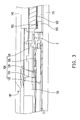
- Fig. 3 is a locally cross-sectional diagram of the LCD of Fig. 1 .
- Fig. 4 is an exploded view of an LCD according to another embodiment of the invention.
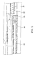
- Fig. 5 is a locally cross-sectional diagram of the LCD of Fig. 4 .
- Fig. 6 is a 3-dimensional diagram showing the inner cover of Fig. 4 locked on the frame.
- Fig. 7 is a locally cross-sectional diagram showing the inner cover of Fig. 4 locked on the frame.
- Fig. 8 is an exploded view of an LCD according to yet another embodiment of the invention.
- Fig. 9 is a locally cross-sectional diagram of the LCD of Fig. 8 .
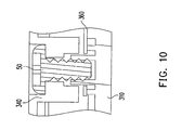
- Fig. 10 is another locally cross-sectional diagram of the LCD of Fig. 8 .
- an LCD 100 of the embodiment includes an outer cover 110, a backlight module 120, a liquid crystal panel 130, and a bezel 140, wherein the backlight module 120 includes a reflection sheet 122, an LGP 124, an edge reflector 126, and a light source 128.
- the reflection sheet 122 is disposed on the outer cover 110 and faces the outer cover 110, and there is an interval D between the outer cover 110 and the reflection sheet 122 so as to avoid the outer cover 110 squeezing the reflection sheet 122 when the outer cover 110 is deformed by applying an external force on the outer cover 110.
- the LGP 124 is stacked on the reflection sheet 122, and the edge reflector 126 is disposed on the outer cover 110.
- a containing space S is defined by the outer cover 110 and the edge reflector 126, and the light source 128 is disposed in the containing space.
- the liquid crystal panel 130 is stacked on the LGP 124.
- the bezel 140 is assembled to the outer cover 110 and has a window 142.
- the bezel 140 has two regions, wherein the window 142 is a transparent region and the peripheral edge surrounding the window 142 is an opaque region.
- the outer cover 110 and the bezel 140 enclose the backlight module 120 and the liquid crystal panel 130, while the window 142 exposes the liquid crystal panel 130, so that, viewing from outside of the bezel 140, the bezel 140 looks as a smooth surface with a nice shape.
- the reflection sheet 122 and the edge reflector 126 are able to reflect the light beam emitted by the light source 128 into the LGP 124, so that the displaying frame of the liquid crystal panel 130 has sufficient luminance to facilitate viewers watching the displaying frame of the liquid crystal panel 130 through the window 142. It should be noted that under the configuration of the embodiment, there is no inner cover between the reflection sheet 122 and the outer cover 110. As a result, the LCD 100 of the embodiment of the invention is lighter and thinner.
- the LCD 100 of the embodiment further includes a frame 150.
- the frame 150 is surrounding the backlight module 120 and connected to the outer cover 110 to fix the backlight module 120.
- the frame 150 has a supporting surface 152 for the liquid crystal panel 130 to be supported on, and there is an interspace between the liquid crystal panel 130 and the backlight module 120 so as to avoid the outer cover 110 squeezing the backlight module 120 and then avoid the backlight module 120 squeezing the liquid crystal panel 130 to damage the liquid crystal panel 130 when the outer cover 110 is deformed by applying an external force on the outer cover 110.
- the liquid crystal panel 130 uses a circuit board 132 thereof to be supported on the supporting surface 152 of the frame 150.
- the frame 150 of the embodiment is, for example, adhesively connected to the outer cover 110
- the bezel 140 is, for example, adhesively connected to the frame 150 so as to make the outer cover 110 and the bezel 140 fixed by each other.
- Such an adhesively assembling method is advantageous in reducing the number of the required fixtures and saving the assembling time.
- the frame 150 has a plurality of positioning grooves 154 and the backlight module 120 further has a plurality of optical films 129 (two ones are shown herein).
- Each of the optical films 129 has a plurality of locking portions 129a, and the locking portions 129a are respectively locked by one of the positioning grooves 154, so that the optical films 129 are able to be assembled within the frame 150 in right orientation.
- the frame 150 functions to fix the backlight module 120, support the liquid crystal panel 130, and lock the optical films 129, and the frame 150 is able to free the LCD 100 from disposing other frames for supporting the liquid crystal panel 130 or locking the optical films 129.
- the LCD 200 of the embodiment further includes an inner cover 260.
- the inner cover 260 is disposed between the outer cover 210 and the reflection sheet 222, and the edge reflector 226 extends from the inner cover 260.
- the inner cover 260 has an opening 262, wherein the reflection sheet 222 directly faces the outer cover 210 through the opening 262.
- the inner cover 260 having the opening 262 is able to further reduce the weight and the thickness of the LCD 200.
- the inner cover 260 of the embodiment has a plurality of locking portions 264
- the frame 250 is adhesive to the outer cover 210 and has a plurality of locking slots 256.
- the locking portions 264 are locked by the locking slots 256 so as to assemble the inner cover 260 to the frame 250.
- the outer cover 310 of the LCD 300 in the embodiment has a plurality of bumps 312.
- the bumps 312 support the backlight module 320 and form an interspace G between the backlight module 320 and the outer cover 310, the interspace G may reduce the probability of overheating the outer cover 310 caused by the thermal energy of the backlight module 320.
- the frame 350 is connected to the outer cover 310 through integrally forming, and a plurality of screws 50 are used to tighten the bezel 340 on the outer cover 310. In this way, the inner cover 360 is fixed between the bezel 340 and the outer cover 310.
- the embodiment or embodiments of the invention may have at least one of the following advantages: there is no inner cover between the reflection sheet and the outer cover, so that the LCD is lighter and thinner.
- the frame for fixing the backlight module further functions to support the liquid crystal panel and lock the optical films, and therefore no additional other frames are required to support the liquid crystal panel or lock the optical films, so that the weight and the thickness of the LCD may be further reduced, and the assembling time and the manufacturing cost may be saved.
- the outer cover, the inner cover, the frame, and the bezel may be made of, for example, metal or plastic. In particular, when at least one of the outer cover, the inner cover, the frame, and the bezel is made of plastic, the weight and the thickness of the LCD may be further reduced.
- the term "the invention”, “the present invention” or the like does not necessarily limit the claim scope to a specific embodiment, and the reference to particularly preferred exemplary embodiments of the invention does not imply a limitation on the invention, and no such limitation is to be inferred.
- the invention is limited only by the spirit and scope of the appended claims.
- the abstract of the disclosure is provided to comply with the rules requiring an abstract, which will allow a searcher to quickly ascertain the subject matter of the technical disclosure of any patent issued from this disclosure. It is submitted with the understanding that it will not be used to interpret or limit the scope or meaning of the claims. Any advantages and benefits described may not apply to all embodiments of the invention.
Landscapes
- Physics & Mathematics (AREA)
- Nonlinear Science (AREA)
- General Physics & Mathematics (AREA)
- Optics & Photonics (AREA)
- Mathematical Physics (AREA)
- Chemical & Material Sciences (AREA)
- Crystallography & Structural Chemistry (AREA)
- Liquid Crystal (AREA)
Abstract
Description
- This application claims the priority benefit of Taiwan application serial no.
98131580, filed on September 18, 2009 - The invention generally relates to a display, and more particularly, to a liquid crystal display (LCD).
- A backlight module used in an LCD of a notebook computer usually has an edge reflector disposed at a side-edge of a light source thereof in addition to having a reflection sheet for reflecting a light beam into a light guide plate (LGP) in the backlight module. For example, Taiwan Patent No.
I257511 M331123 - Usually, a plurality of frames are disposed between an outer cover and a bezel of an LCD, and the frames are for fixing the above-mentioned edge reflector and other parts in the LCD. However, too many disposed frames would apparently increase the thickness and the weight of the LCD and also increase the assembling time and the manufacturing cost. To solve the above-mentioned problem, Taiwan Patent No.
575767 - In addition, the LCD usually employs an inner cover disposed between the reflection sheet and the outer cover thereof, where the inner cover extends from a location under the light source to a location over the light source so as to defme the above-mentioned edge reflector. Obviously, the above-mentioned inner cover would increase the thickness and the weight of the LCD as well, and the inner cover makes a notebook computer inconvenient for carrying.
- Accordingly, the invention is directed to an LCD with lighter and thinner configuration.
- Other advantages of the invention should be further indicated by the disclosures of the invention, and omitted herein for simplicity.
- To achieve one of, a part of or all of the above-mentioned advantages, or to achieve other advantages, an embodiment of the invention provides an LCD, the LCD includes an outer cover, a backlight module, a liquid crystal panel, and a bezel. The backlight module includes a reflection sheet, a light guide plate (LGP), an edge reflector, and a light source. The reflection sheet is disposed on the outer cover and faces the outer cover. There is an interval between the outer cover and the reflection sheet. The LGP is stacked on the reflection sheet, and the edge reflector is disposed on the outer cover, wherein a containing space is defined by the outer cover and the edge reflector. The light source is disposed in the containing space. The liquid crystal panel is stacked on the LGP. The bezel is assembled to the outer cover and has a window. The outer cover and the bezel enclose the backlight module and the liquid crystal panel, and the window exposes the liquid crystal panel.
- Based on the depiction above, the embodiment or embodiments of the invention may have at least one of the following advantages: there is no inner cover between the reflection sheet and the outer cover, and no inner cover is advantageous to make the LCD lighter and thinner.
- Other objectives, features and advantages of the present invention will be further understood from the further technological features disclosed by the embodiments of the present invention wherein there are shown and described preferred embodiments of this invention, simply by way of illustration of modes best suited to carry out the invention.
- The accompanying drawings are included to provide a further understanding of the invention, and are incorporated in and constitute a part of this specification. The drawings illustrate embodiments of the invention and, together with the description, serve to explain the principles of the invention.
-
Fig. 1 is a 3-dimensional diagram of an LCD according to an embodiment of the invention. -
Fig. 2 is an exploded view of the LCD ofFig. 1 . -
Fig. 3 is a locally cross-sectional diagram of the LCD ofFig. 1 . -
Fig. 4 is an exploded view of an LCD according to another embodiment of the invention. -
Fig. 5 is a locally cross-sectional diagram of the LCD ofFig. 4 . -
Fig. 6 is a 3-dimensional diagram showing the inner cover ofFig. 4 locked on the frame. -
Fig. 7 is a locally cross-sectional diagram showing the inner cover ofFig. 4 locked on the frame. -
Fig. 8 is an exploded view of an LCD according to yet another embodiment of the invention. -
Fig. 9 is a locally cross-sectional diagram of the LCD ofFig. 8 . -
Fig. 10 is another locally cross-sectional diagram of the LCD ofFig. 8 . - In the following detailed description of the preferred embodiments, reference is made to the accompanying drawings which form a part hereof, and in which are shown by way of illustration specific embodiments in which the invention may be practiced. In this regard, directional terminology, such as "top," "bottom," "front," "back," etc., is used with reference to the orientation of the Figure(s) being described. The components of the present invention can be positioned in a number of different orientations. As such, the directional terminology is used for purposes of illustration and is in no way limiting. On the other hand, the drawings are only schematic and the sizes of components may be exaggerated for clarity. It is to be understood that other embodiments may be utilized and structural changes may be made without departing from the scope of the present invention. Also, it is to be understood that the phraseology and terminology used herein are for the purpose of description and should not be regarded as limiting. The use of "including," "comprising," or "having" and variations thereof herein is meant to encompass the items listed thereafter and equivalents thereof as well as additional items. Unless limited otherwise, the terms "connected," "coupled," and "mounted" and variations thereof herein are used broadly and encompass direct and indirect connections, couplings, and mountings. Similarly, the terms "facing," "faces" and variations thereof herein are used broadly and encompass direct and indirect facing, and "adjacent to" and variations thereof herein are used broadly and encompass directly and indirectly "adjacent to". Therefore, the description of "A" component facing "B" component herein may contain the situations that "A" component directly faces "B" component or one or more additional components are between "A" component and "B" component. Also, the description of "A" component "adjacent to" "B" component herein may contain the situations that "A" component is directly "adjacent to" "B" component or one or more additional components are between "A" component and "B" component. Accordingly, the drawings and descriptions will be regarded as illustrative in nature and not as restrictive.
- Referring to
Figs. 1-3 , anLCD 100 of the embodiment includes anouter cover 110, abacklight module 120, aliquid crystal panel 130, and abezel 140, wherein thebacklight module 120 includes areflection sheet 122, an LGP 124, anedge reflector 126, and alight source 128. - The
reflection sheet 122 is disposed on theouter cover 110 and faces theouter cover 110, and there is an interval D between theouter cover 110 and thereflection sheet 122 so as to avoid theouter cover 110 squeezing thereflection sheet 122 when theouter cover 110 is deformed by applying an external force on theouter cover 110. The LGP 124 is stacked on thereflection sheet 122, and theedge reflector 126 is disposed on theouter cover 110. A containing space S is defined by theouter cover 110 and theedge reflector 126, and thelight source 128 is disposed in the containing space. Theliquid crystal panel 130 is stacked on the LGP 124. Thebezel 140 is assembled to theouter cover 110 and has awindow 142. In more details, thebezel 140 has two regions, wherein thewindow 142 is a transparent region and the peripheral edge surrounding thewindow 142 is an opaque region. Theouter cover 110 and thebezel 140 enclose thebacklight module 120 and theliquid crystal panel 130, while thewindow 142 exposes theliquid crystal panel 130, so that, viewing from outside of thebezel 140, thebezel 140 looks as a smooth surface with a nice shape. - The
reflection sheet 122 and theedge reflector 126 are able to reflect the light beam emitted by thelight source 128 into theLGP 124, so that the displaying frame of theliquid crystal panel 130 has sufficient luminance to facilitate viewers watching the displaying frame of theliquid crystal panel 130 through thewindow 142. It should be noted that under the configuration of the embodiment, there is no inner cover between thereflection sheet 122 and theouter cover 110. As a result, theLCD 100 of the embodiment of the invention is lighter and thinner. - Referring to
Figs. 2 and3 , theLCD 100 of the embodiment further includes aframe 150. Theframe 150 is surrounding thebacklight module 120 and connected to theouter cover 110 to fix thebacklight module 120. Theframe 150 has a supportingsurface 152 for theliquid crystal panel 130 to be supported on, and there is an interspace between theliquid crystal panel 130 and thebacklight module 120 so as to avoid theouter cover 110 squeezing thebacklight module 120 and then avoid thebacklight module 120 squeezing theliquid crystal panel 130 to damage theliquid crystal panel 130 when theouter cover 110 is deformed by applying an external force on theouter cover 110. In more details, theliquid crystal panel 130 uses acircuit board 132 thereof to be supported on the supportingsurface 152 of theframe 150. Theframe 150 of the embodiment is, for example, adhesively connected to theouter cover 110, and thebezel 140 is, for example, adhesively connected to theframe 150 so as to make theouter cover 110 and thebezel 140 fixed by each other. Such an adhesively assembling method is advantageous in reducing the number of the required fixtures and saving the assembling time. Besides, theframe 150 has a plurality ofpositioning grooves 154 and thebacklight module 120 further has a plurality of optical films 129 (two ones are shown herein). Each of theoptical films 129 has a plurality of locking portions 129a, and the locking portions 129a are respectively locked by one of thepositioning grooves 154, so that theoptical films 129 are able to be assembled within theframe 150 in right orientation. - In other words, the
frame 150 functions to fix thebacklight module 120, support theliquid crystal panel 130, and lock theoptical films 129, and theframe 150 is able to free theLCD 100 from disposing other frames for supporting theliquid crystal panel 130 or locking theoptical films 129. - Referring to
Figs. 4 and5 , in comparison with theLCD 100 ofFigs. 1-3 , theLCD 200 of the embodiment further includes aninner cover 260. Theinner cover 260 is disposed between theouter cover 210 and thereflection sheet 222, and theedge reflector 226 extends from theinner cover 260. Theinner cover 260 has anopening 262, wherein thereflection sheet 222 directly faces theouter cover 210 through theopening 262. Herein, theinner cover 260 having theopening 262 is able to further reduce the weight and the thickness of theLCD 200. - Referring to
Figs. 4 ,6 and7 , theinner cover 260 of the embodiment has a plurality of lockingportions 264, and theframe 250 is adhesive to theouter cover 210 and has a plurality of lockingslots 256. The lockingportions 264 are locked by the lockingslots 256 so as to assemble theinner cover 260 to theframe 250. - Referring to
Figs. 8 and9 , in comparison with theLCD 200 ofFigs. 4 and5 , theouter cover 310 of theLCD 300 in the embodiment has a plurality ofbumps 312. Thebumps 312 support thebacklight module 320 and form an interspace G between thebacklight module 320 and theouter cover 310, the interspace G may reduce the probability of overheating theouter cover 310 caused by the thermal energy of thebacklight module 320. - Referring to
Figs. 8 and10 , in comparison withFig. 6 where theframe 250 is adhesively connected to theouter cover 210 and theinner cover 260 is locked within theframe 250, in the embodiment, theframe 350 is connected to theouter cover 310 through integrally forming, and a plurality ofscrews 50 are used to tighten thebezel 340 on theouter cover 310. In this way, theinner cover 360 is fixed between thebezel 340 and theouter cover 310. - In summary, the embodiment or embodiments of the invention may have at least one of the following advantages: there is no inner cover between the reflection sheet and the outer cover, so that the LCD is lighter and thinner. In addition, the frame for fixing the backlight module further functions to support the liquid crystal panel and lock the optical films, and therefore no additional other frames are required to support the liquid crystal panel or lock the optical films, so that the weight and the thickness of the LCD may be further reduced, and the assembling time and the manufacturing cost may be saved. Besides, in the above-mentioned embodiments of the invention, the outer cover, the inner cover, the frame, and the bezel may be made of, for example, metal or plastic. In particular, when at least one of the outer cover, the inner cover, the frame, and the bezel is made of plastic, the weight and the thickness of the LCD may be further reduced.
- The foregoing description of the preferred embodiments of the invention has been presented for purposes of illustration and description. It is not intended to be exhaustive or to limit the invention to the precise form or to exemplary embodiments disclosed. Accordingly, the foregoing description should be regarded as illustrative rather than restrictive. Obviously, many modifications and variations will be apparent to practitioners skilled in this art. The embodiments are chosen and described in order to best explain the principles of the invention and its best mode practical application, thereby to enable persons skilled in the art to understand the invention for various embodiments and with various modifications as are suited to the particular use or implementation contemplated. It is intended that the scope of the invention be defined by the claims appended hereto and their equivalents in which all terms are meant in their broadest reasonable sense unless otherwise indicated. Therefore, the term "the invention", "the present invention" or the like does not necessarily limit the claim scope to a specific embodiment, and the reference to particularly preferred exemplary embodiments of the invention does not imply a limitation on the invention, and no such limitation is to be inferred. The invention is limited only by the spirit and scope of the appended claims. The abstract of the disclosure is provided to comply with the rules requiring an abstract, which will allow a searcher to quickly ascertain the subject matter of the technical disclosure of any patent issued from this disclosure. It is submitted with the understanding that it will not be used to interpret or limit the scope or meaning of the claims. Any advantages and benefits described may not apply to all embodiments of the invention. It should be appreciated that variations may be made in the embodiments described by persons skilled in the art without departing from the scope of the present invention as defined by the following claims. Moreover, no element and component in the present disclosure is intended to be dedicated to the public regardless of whether the element or component is explicitly recited in the following claims.
Claims (10)
- A liquid crystal display, comprising:an outer cover;a backlight module, comprising:a reflection sheet, disposed on the outer cover and facing the outer cover, wherein there is an interval between the outer cover and the reflection sheet;a light guide plate, stacked on the reflection sheet;an edge reflector, disposed on the outer cover, wherein a containing space is defined by the outer cover and the edge reflector;a light source, disposed in the containing space;a liquid crystal panel, stacked on the light guide plate; anda bezel, assembled to the outer cover and having a window, wherein the outer cover and the bezel enclose the backlight module and the liquid crystal panel, and the window exposes the liquid crystal panel.
- The liquid crystal display as claimed in claim 1, further comprising:a frame, surrounding the backlight module, connected to the outer cover, and having a supporting surface, wherein the liquid crystal panel is supported on the supporting surface.
- The liquid crystal display as claimed in claim 2, wherein the frame has a plurality of positioning grooves, and the backlight module further comprises:an optical film, having a plurality of locking portions, wherein the locking portions are respectively locked by the positioning grooves.
- The liquid crystal display as claimed in claim 2, wherein the frame is adhesively connected to the outer cover.
- The liquid crystal display as claimed in claim 2, wherein the frame is connected to the outer cover through integrally forming.
- The liquid crystal display as claimed in claim 2, wherein the bezel is adhesively connected to the frame.
- The liquid crystal display as claimed in claim 2, further comprising:an inner cover, disposed between the outer cover and the reflection sheet and having the edge reflector and an opening, wherein the reflection sheet directly faces the outer cover through the opening.
- The liquid crystal display as claimed in claim 7, wherein the inner cover is locked on the frame.
- The liquid crystal display as claimed in claim 7, wherein the inner cover is screwedly fixed on the outer cover.
- The liquid crystal display as claimed in claim 1, wherein the outer cover has a plurality of bumps, and the bumps support the backlight module and form an interspace between the backlight module and the outer cover.
Applications Claiming Priority (1)
| Application Number | Priority Date | Filing Date | Title |
|---|---|---|---|
| TW098131580A TWI393953B (en) | 2009-09-18 | 2009-09-18 | Liquid crystal display |
Publications (3)
| Publication Number | Publication Date |
|---|---|
| EP2299315A2 true EP2299315A2 (en) | 2011-03-23 |
| EP2299315A3 EP2299315A3 (en) | 2011-11-23 |
| EP2299315B1 EP2299315B1 (en) | 2017-08-02 |
Family
ID=43303714
Family Applications (1)
| Application Number | Title | Priority Date | Filing Date |
|---|---|---|---|
| EP10009395.4A Not-in-force EP2299315B1 (en) | 2009-09-18 | 2010-09-09 | Liquid crystal display |
Country Status (3)
| Country | Link |
|---|---|
| US (1) | US8704968B2 (en) |
| EP (1) | EP2299315B1 (en) |
| TW (1) | TWI393953B (en) |
Families Citing this family (2)
| Publication number | Priority date | Publication date | Assignee | Title |
|---|---|---|---|---|
| TWI526074B (en) | 2011-09-26 | 2016-03-11 | 仁寶電腦工業股份有限公司 | Display and assembling method thereof |
| TWI514219B (en) | 2013-12-17 | 2015-12-21 | Ind Tech Res Inst | Bending sensor and associated bending sensing method and system applied to flexible display panel |
Citations (2)
| Publication number | Priority date | Publication date | Assignee | Title |
|---|---|---|---|---|
| TW331123U (en) | 1997-06-06 | 1998-05-01 | Jian-Qiao Cao | Vacuum cleaner of grasping type |
| TW575767B (en) | 2001-12-03 | 2004-02-11 | Nec Lcd Technologies Ltd | Liquid crystal display and method for fabricating same |
Family Cites Families (18)
| Publication number | Priority date | Publication date | Assignee | Title |
|---|---|---|---|---|
| JP3059066B2 (en) * | 1994-12-13 | 2000-07-04 | シャープ株式会社 | Liquid crystal display |
| KR100246849B1 (en) * | 1997-06-30 | 2000-03-15 | 윤종용 | Liquid crystal display |
| JPH11102160A (en) * | 1997-09-29 | 1999-04-13 | Mitsubishi Electric Corp | Liquid crystal panel module and liquid crystal display device using the liquid crystal panel module |
| KR100319199B1 (en) * | 1998-09-24 | 2002-10-25 | 삼성전자 주식회사 | LCD Display |
| KR100473227B1 (en) | 2000-02-24 | 2005-03-07 | 엘지.필립스 엘시디 주식회사 | Structure of Preventing Wrinkle of a Reflective Sheet of Backlight Unit |
| JP3334800B2 (en) | 2000-03-23 | 2002-10-15 | 日本電気株式会社 | Liquid crystal display |
| KR100863998B1 (en) * | 2002-06-19 | 2008-10-16 | 삼성전자주식회사 | Liquid crystal display module and liquid crystal display device using same |
| KR100819709B1 (en) | 2003-09-29 | 2008-04-04 | 엘지.필립스 엘시디 주식회사 | Module of LCD |
| TWI257511B (en) | 2004-02-18 | 2006-07-01 | Quanta Display Inc | Back light module of liquid crystal display |
| KR100999011B1 (en) * | 2004-04-30 | 2010-12-09 | 엘지디스플레이 주식회사 | Backlight unit and liquid crystal display using the same |
| TWI287149B (en) | 2005-08-26 | 2007-09-21 | Innolux Display Corp | Backlight module and method of manufacturing the same |
| KR101203661B1 (en) * | 2005-10-14 | 2012-11-23 | 삼성디스플레이 주식회사 | Backlight assembly and liquid crystal display having the same |
| TWI321695B (en) | 2006-05-16 | 2010-03-11 | Coretronic Corp | Backlight module housing and liquid crystal display device |
| JP2008198540A (en) * | 2007-02-15 | 2008-08-28 | Epson Imaging Devices Corp | Optical sheet, backlight device using the optical sheet, and liquid crystal display device |
| KR101319590B1 (en) * | 2007-02-15 | 2013-10-16 | 삼성디스플레이 주식회사 | Liquid crystal display device and tablet personal computer having the same |
| TWM331123U (en) | 2007-08-24 | 2008-04-21 | Coretronic Corp | Backlight module and a liquid crystal display |
| JP4422748B2 (en) * | 2007-09-07 | 2010-02-24 | 株式会社日立製作所 | Liquid crystal display |
| TWM350935U (en) | 2008-09-19 | 2009-02-11 | Top Victory Invest Ltd | Liquid crystal displayer |
-
2009
- 2009-09-18 TW TW098131580A patent/TWI393953B/en active
-
2010
- 2010-08-06 US US12/851,563 patent/US8704968B2/en active Active
- 2010-09-09 EP EP10009395.4A patent/EP2299315B1/en not_active Not-in-force
Patent Citations (2)
| Publication number | Priority date | Publication date | Assignee | Title |
|---|---|---|---|---|
| TW331123U (en) | 1997-06-06 | 1998-05-01 | Jian-Qiao Cao | Vacuum cleaner of grasping type |
| TW575767B (en) | 2001-12-03 | 2004-02-11 | Nec Lcd Technologies Ltd | Liquid crystal display and method for fabricating same |
Also Published As
| Publication number | Publication date |
|---|---|
| TWI393953B (en) | 2013-04-21 |
| TW201111865A (en) | 2011-04-01 |
| EP2299315B1 (en) | 2017-08-02 |
| EP2299315A3 (en) | 2011-11-23 |
| US8704968B2 (en) | 2014-04-22 |
| US20110069248A1 (en) | 2011-03-24 |
Similar Documents
| Publication | Publication Date | Title |
|---|---|---|
| US8054407B2 (en) | Liquid crystal display device | |
| US10788707B2 (en) | Curved display device with arc-shaped fixing members | |
| TWI289227B (en) | Liquid crystal display | |
| US10247877B2 (en) | Backlight module and a liquid crystal display apparatus having the same | |
| US20110102701A1 (en) | Liquid crystal display device | |
| JP5173640B2 (en) | Backlight unit and method for assembling the same | |
| JP2003043943A (en) | Flat panel display connection structure | |
| WO2017185594A1 (en) | Backlight module, display module and display device | |
| CN110361880A (en) | Display module and its assemble method, display device | |
| TWI459091B (en) | Backlight module and display device using the same | |
| US20110058355A1 (en) | Liquid crystal display device and method for assembling same | |
| US8174638B2 (en) | Liquid crystal display device | |
| JP2004126287A (en) | Liquid crystal display and its manufacturing method | |
| CN101487943B (en) | Backlight module and liquid crystal display using same | |
| US8704968B2 (en) | Liquid crystal display | |
| TWI254173B (en) | Liquid crystal display module | |
| CN114509891A (en) | Backlight module and display device | |
| JP4439656B2 (en) | LIGHTING UNIT AND ITS MANUFACTURING METHOD, AND LIQUID CRYSTAL DISPLAY DEVICE USING THE LIGHTING UNIT AND ITS MANUFACTURING METHOD | |
| CN211905923U (en) | Display device | |
| CN221008040U (en) | Display device and display apparatus | |
| US20080007968A1 (en) | Double-layer lamp and backlight module having same field of the invention | |
| KR20050067858A (en) | Backlight unit | |
| WO2019184412A1 (en) | Backlight module and liquid crystal display device | |
| JP2009266796A (en) | Reflective back plate and direct backlight module | |
| US20080013337A1 (en) | Backlight module and liquid crystal display |
Legal Events
| Date | Code | Title | Description |
|---|---|---|---|
| PUAI | Public reference made under article 153(3) epc to a published international application that has entered the european phase |
Free format text: ORIGINAL CODE: 0009012 |
|
| AK | Designated contracting states |
Kind code of ref document: A2 Designated state(s): AL AT BE BG CH CY CZ DE DK EE ES FI FR GB GR HR HU IE IS IT LI LT LU LV MC MK MT NL NO PL PT RO SE SI SK SM TR |
|
| AX | Request for extension of the european patent |
Extension state: BA ME RS |
|
| PUAL | Search report despatched |
Free format text: ORIGINAL CODE: 0009013 |
|
| AK | Designated contracting states |
Kind code of ref document: A3 Designated state(s): AL AT BE BG CH CY CZ DE DK EE ES FI FR GB GR HR HU IE IS IT LI LT LU LV MC MK MT NL NO PL PT RO SE SI SK SM TR |
|
| AX | Request for extension of the european patent |
Extension state: BA ME RS |
|
| RIC1 | Information provided on ipc code assigned before grant |
Ipc: G02F 1/13357 20060101ALI20111020BHEP Ipc: G02B 6/00 20060101ALI20111020BHEP Ipc: G02F 1/1333 20060101AFI20111020BHEP |
|
| 17P | Request for examination filed |
Effective date: 20120522 |
|
| 17Q | First examination report despatched |
Effective date: 20131101 |
|
| GRAP | Despatch of communication of intention to grant a patent |
Free format text: ORIGINAL CODE: EPIDOSNIGR1 |
|
| INTG | Intention to grant announced |
Effective date: 20170310 |
|
| GRAS | Grant fee paid |
Free format text: ORIGINAL CODE: EPIDOSNIGR3 |
|
| GRAA | (expected) grant |
Free format text: ORIGINAL CODE: 0009210 |
|
| AK | Designated contracting states |
Kind code of ref document: B1 Designated state(s): AL AT BE BG CH CY CZ DE DK EE ES FI FR GB GR HR HU IE IS IT LI LT LU LV MC MK MT NL NO PL PT RO SE SI SK SM TR |
|
| REG | Reference to a national code |
Ref country code: GB Ref legal event code: FG4D |
|
| REG | Reference to a national code |
Ref country code: CH Ref legal event code: EP Ref country code: AT Ref legal event code: REF Ref document number: 915104 Country of ref document: AT Kind code of ref document: T Effective date: 20170815 |
|
| REG | Reference to a national code |
Ref country code: IE Ref legal event code: FG4D |
|
| REG | Reference to a national code |
Ref country code: DE Ref legal event code: R096 Ref document number: 602010043997 Country of ref document: DE |
|
| REG | Reference to a national code |
Ref country code: FR Ref legal event code: PLFP Year of fee payment: 8 |
|
| REG | Reference to a national code |
Ref country code: NL Ref legal event code: MP Effective date: 20170802 |
|
| REG | Reference to a national code |
Ref country code: AT Ref legal event code: MK05 Ref document number: 915104 Country of ref document: AT Kind code of ref document: T Effective date: 20170802 |
|
| REG | Reference to a national code |
Ref country code: LT Ref legal event code: MG4D |
|
| PG25 | Lapsed in a contracting state [announced via postgrant information from national office to epo] |
Ref country code: AT Free format text: LAPSE BECAUSE OF FAILURE TO SUBMIT A TRANSLATION OF THE DESCRIPTION OR TO PAY THE FEE WITHIN THE PRESCRIBED TIME-LIMIT Effective date: 20170802 Ref country code: HR Free format text: LAPSE BECAUSE OF FAILURE TO SUBMIT A TRANSLATION OF THE DESCRIPTION OR TO PAY THE FEE WITHIN THE PRESCRIBED TIME-LIMIT Effective date: 20170802 Ref country code: NL Free format text: LAPSE BECAUSE OF FAILURE TO SUBMIT A TRANSLATION OF THE DESCRIPTION OR TO PAY THE FEE WITHIN THE PRESCRIBED TIME-LIMIT Effective date: 20170802 Ref country code: FI Free format text: LAPSE BECAUSE OF FAILURE TO SUBMIT A TRANSLATION OF THE DESCRIPTION OR TO PAY THE FEE WITHIN THE PRESCRIBED TIME-LIMIT Effective date: 20170802 Ref country code: SE Free format text: LAPSE BECAUSE OF FAILURE TO SUBMIT A TRANSLATION OF THE DESCRIPTION OR TO PAY THE FEE WITHIN THE PRESCRIBED TIME-LIMIT Effective date: 20170802 Ref country code: NO Free format text: LAPSE BECAUSE OF FAILURE TO SUBMIT A TRANSLATION OF THE DESCRIPTION OR TO PAY THE FEE WITHIN THE PRESCRIBED TIME-LIMIT Effective date: 20171102 Ref country code: LT Free format text: LAPSE BECAUSE OF FAILURE TO SUBMIT A TRANSLATION OF THE DESCRIPTION OR TO PAY THE FEE WITHIN THE PRESCRIBED TIME-LIMIT Effective date: 20170802 |
|
| PG25 | Lapsed in a contracting state [announced via postgrant information from national office to epo] |
Ref country code: GR Free format text: LAPSE BECAUSE OF FAILURE TO SUBMIT A TRANSLATION OF THE DESCRIPTION OR TO PAY THE FEE WITHIN THE PRESCRIBED TIME-LIMIT Effective date: 20171103 Ref country code: ES Free format text: LAPSE BECAUSE OF FAILURE TO SUBMIT A TRANSLATION OF THE DESCRIPTION OR TO PAY THE FEE WITHIN THE PRESCRIBED TIME-LIMIT Effective date: 20170802 Ref country code: LV Free format text: LAPSE BECAUSE OF FAILURE TO SUBMIT A TRANSLATION OF THE DESCRIPTION OR TO PAY THE FEE WITHIN THE PRESCRIBED TIME-LIMIT Effective date: 20170802 Ref country code: IS Free format text: LAPSE BECAUSE OF FAILURE TO SUBMIT A TRANSLATION OF THE DESCRIPTION OR TO PAY THE FEE WITHIN THE PRESCRIBED TIME-LIMIT Effective date: 20171202 Ref country code: PL Free format text: LAPSE BECAUSE OF FAILURE TO SUBMIT A TRANSLATION OF THE DESCRIPTION OR TO PAY THE FEE WITHIN THE PRESCRIBED TIME-LIMIT Effective date: 20170802 Ref country code: BG Free format text: LAPSE BECAUSE OF FAILURE TO SUBMIT A TRANSLATION OF THE DESCRIPTION OR TO PAY THE FEE WITHIN THE PRESCRIBED TIME-LIMIT Effective date: 20171102 |
|
| PG25 | Lapsed in a contracting state [announced via postgrant information from national office to epo] |
Ref country code: CZ Free format text: LAPSE BECAUSE OF FAILURE TO SUBMIT A TRANSLATION OF THE DESCRIPTION OR TO PAY THE FEE WITHIN THE PRESCRIBED TIME-LIMIT Effective date: 20170802 Ref country code: RO Free format text: LAPSE BECAUSE OF FAILURE TO SUBMIT A TRANSLATION OF THE DESCRIPTION OR TO PAY THE FEE WITHIN THE PRESCRIBED TIME-LIMIT Effective date: 20170802 Ref country code: DK Free format text: LAPSE BECAUSE OF FAILURE TO SUBMIT A TRANSLATION OF THE DESCRIPTION OR TO PAY THE FEE WITHIN THE PRESCRIBED TIME-LIMIT Effective date: 20170802 |
|
| REG | Reference to a national code |
Ref country code: CH Ref legal event code: PL |
|
| REG | Reference to a national code |
Ref country code: DE Ref legal event code: R097 Ref document number: 602010043997 Country of ref document: DE |
|
| PG25 | Lapsed in a contracting state [announced via postgrant information from national office to epo] |
Ref country code: MC Free format text: LAPSE BECAUSE OF FAILURE TO SUBMIT A TRANSLATION OF THE DESCRIPTION OR TO PAY THE FEE WITHIN THE PRESCRIBED TIME-LIMIT Effective date: 20170802 Ref country code: SM Free format text: LAPSE BECAUSE OF FAILURE TO SUBMIT A TRANSLATION OF THE DESCRIPTION OR TO PAY THE FEE WITHIN THE PRESCRIBED TIME-LIMIT Effective date: 20170802 Ref country code: SK Free format text: LAPSE BECAUSE OF FAILURE TO SUBMIT A TRANSLATION OF THE DESCRIPTION OR TO PAY THE FEE WITHIN THE PRESCRIBED TIME-LIMIT Effective date: 20170802 Ref country code: EE Free format text: LAPSE BECAUSE OF FAILURE TO SUBMIT A TRANSLATION OF THE DESCRIPTION OR TO PAY THE FEE WITHIN THE PRESCRIBED TIME-LIMIT Effective date: 20170802 Ref country code: IT Free format text: LAPSE BECAUSE OF FAILURE TO SUBMIT A TRANSLATION OF THE DESCRIPTION OR TO PAY THE FEE WITHIN THE PRESCRIBED TIME-LIMIT Effective date: 20170802 |
|
| PLBE | No opposition filed within time limit |
Free format text: ORIGINAL CODE: 0009261 |
|
| STAA | Information on the status of an ep patent application or granted ep patent |
Free format text: STATUS: NO OPPOSITION FILED WITHIN TIME LIMIT |
|
| REG | Reference to a national code |
Ref country code: IE Ref legal event code: MM4A |
|
| REG | Reference to a national code |
Ref country code: BE Ref legal event code: MM Effective date: 20170930 |
|
| PG25 | Lapsed in a contracting state [announced via postgrant information from national office to epo] |
Ref country code: LU Free format text: LAPSE BECAUSE OF NON-PAYMENT OF DUE FEES Effective date: 20170909 |
|
| 26N | No opposition filed |
Effective date: 20180503 |
|
| PG25 | Lapsed in a contracting state [announced via postgrant information from national office to epo] |
Ref country code: CH Free format text: LAPSE BECAUSE OF NON-PAYMENT OF DUE FEES Effective date: 20170930 Ref country code: IE Free format text: LAPSE BECAUSE OF NON-PAYMENT OF DUE FEES Effective date: 20170909 Ref country code: LI Free format text: LAPSE BECAUSE OF NON-PAYMENT OF DUE FEES Effective date: 20170930 |
|
| PG25 | Lapsed in a contracting state [announced via postgrant information from national office to epo] |
Ref country code: SI Free format text: LAPSE BECAUSE OF FAILURE TO SUBMIT A TRANSLATION OF THE DESCRIPTION OR TO PAY THE FEE WITHIN THE PRESCRIBED TIME-LIMIT Effective date: 20170802 Ref country code: BE Free format text: LAPSE BECAUSE OF NON-PAYMENT OF DUE FEES Effective date: 20170930 |
|
| REG | Reference to a national code |
Ref country code: FR Ref legal event code: PLFP Year of fee payment: 9 |
|
| PG25 | Lapsed in a contracting state [announced via postgrant information from national office to epo] |
Ref country code: MT Free format text: LAPSE BECAUSE OF NON-PAYMENT OF DUE FEES Effective date: 20170909 |
|
| PG25 | Lapsed in a contracting state [announced via postgrant information from national office to epo] |
Ref country code: HU Free format text: LAPSE BECAUSE OF FAILURE TO SUBMIT A TRANSLATION OF THE DESCRIPTION OR TO PAY THE FEE WITHIN THE PRESCRIBED TIME-LIMIT; INVALID AB INITIO Effective date: 20100909 |
|
| PG25 | Lapsed in a contracting state [announced via postgrant information from national office to epo] |
Ref country code: CY Free format text: LAPSE BECAUSE OF NON-PAYMENT OF DUE FEES Effective date: 20170802 |
|
| PG25 | Lapsed in a contracting state [announced via postgrant information from national office to epo] |
Ref country code: MK Free format text: LAPSE BECAUSE OF FAILURE TO SUBMIT A TRANSLATION OF THE DESCRIPTION OR TO PAY THE FEE WITHIN THE PRESCRIBED TIME-LIMIT Effective date: 20170802 |
|
| PG25 | Lapsed in a contracting state [announced via postgrant information from national office to epo] |
Ref country code: TR Free format text: LAPSE BECAUSE OF FAILURE TO SUBMIT A TRANSLATION OF THE DESCRIPTION OR TO PAY THE FEE WITHIN THE PRESCRIBED TIME-LIMIT Effective date: 20170802 |
|
| PG25 | Lapsed in a contracting state [announced via postgrant information from national office to epo] |
Ref country code: PT Free format text: LAPSE BECAUSE OF FAILURE TO SUBMIT A TRANSLATION OF THE DESCRIPTION OR TO PAY THE FEE WITHIN THE PRESCRIBED TIME-LIMIT Effective date: 20170802 |
|
| PG25 | Lapsed in a contracting state [announced via postgrant information from national office to epo] |
Ref country code: AL Free format text: LAPSE BECAUSE OF FAILURE TO SUBMIT A TRANSLATION OF THE DESCRIPTION OR TO PAY THE FEE WITHIN THE PRESCRIBED TIME-LIMIT Effective date: 20170802 |
|
| PGFP | Annual fee paid to national office [announced via postgrant information from national office to epo] |
Ref country code: GB Payment date: 20220927 Year of fee payment: 13 Ref country code: DE Payment date: 20220818 Year of fee payment: 13 |
|
| PGFP | Annual fee paid to national office [announced via postgrant information from national office to epo] |
Ref country code: FR Payment date: 20220920 Year of fee payment: 13 |
|
| REG | Reference to a national code |
Ref country code: DE Ref legal event code: R119 Ref document number: 602010043997 Country of ref document: DE |
|
| GBPC | Gb: european patent ceased through non-payment of renewal fee |
Effective date: 20230909 |
|
| PG25 | Lapsed in a contracting state [announced via postgrant information from national office to epo] |
Ref country code: GB Free format text: LAPSE BECAUSE OF NON-PAYMENT OF DUE FEES Effective date: 20230909 |
|
| PG25 | Lapsed in a contracting state [announced via postgrant information from national office to epo] |
Ref country code: GB Free format text: LAPSE BECAUSE OF NON-PAYMENT OF DUE FEES Effective date: 20230909 Ref country code: FR Free format text: LAPSE BECAUSE OF NON-PAYMENT OF DUE FEES Effective date: 20230930 Ref country code: DE Free format text: LAPSE BECAUSE OF NON-PAYMENT OF DUE FEES Effective date: 20240403 |