EP2299303A2 - Multimode optical fibre with reduced bending loss - Google Patents
Multimode optical fibre with reduced bending loss Download PDFInfo
- Publication number
- EP2299303A2 EP2299303A2 EP10176645A EP10176645A EP2299303A2 EP 2299303 A2 EP2299303 A2 EP 2299303A2 EP 10176645 A EP10176645 A EP 10176645A EP 10176645 A EP10176645 A EP 10176645A EP 2299303 A2 EP2299303 A2 EP 2299303A2
- Authority
- EP
- European Patent Office
- Prior art keywords
- fibre
- index
- core
- cladding
- optical
- Prior art date
- Legal status (The legal status is an assumption and is not a legal conclusion. Google has not performed a legal analysis and makes no representation as to the accuracy of the status listed.)
- Granted
Links
Images



Classifications
-
- G—PHYSICS
- G02—OPTICS
- G02B—OPTICAL ELEMENTS, SYSTEMS OR APPARATUS
- G02B6/00—Light guides; Structural details of arrangements comprising light guides and other optical elements, e.g. couplings
- G02B6/02—Optical fibres with cladding with or without a coating
- G02B6/028—Optical fibres with cladding with or without a coating with core or cladding having graded refractive index
- G02B6/0288—Multimode fibre, e.g. graded index core for compensating modal dispersion
Definitions
- the present invention relates to the field of optical fibre transmissions, and more specifically, to a multimode optical fibre having greatly reduced bending losses for use in high-speed applications.
- an optical fibre is composed of an optical core having the function of transmitting and optionally amplifying an optical signal, and an outer optical cladding having the function of confining the optical signal within the optical core.
- the refractive indices of the optical core n core and of the outer optical cladding n cladding are such that n core >n cladding .
- the refractive index profile of a fibre denotes the graph associating the refractive index with the radius of the fibre.
- the distance to the centre of the fibre is shown on the x-axis, and on the y-axis, the difference is shown between the refractive index of the fibre at radius r and the refractive index of the cladding of the fibre.
- the refractive index profile is qualified according to its appearance.
- the index profile is described in terms of a "step”, “trapezium”, “triangle”, or “alpha” for graphs which have step, trapezium, triangle, or graded ( ⁇ ) shapes respectively.
- multimode fibres Two main types of optical fibres exist, multimode fibres and single mode fibres.
- a multimode fibre for a given wavelength, several optical modes are propagated simultaneously along the fibre, whereas in a single mode fibre optical modes of a higher order are strongly attenuated.
- the typical diameter of a single mode or multimode optical fibre is 125 ⁇ m.
- the core of a multimode fibre typically has a diameter of 50 ⁇ m or 62.5 ⁇ m, whereas the core of a single-mode fibre generally has a diameter of approximately 6 ⁇ m to 9 ⁇ m.
- the multimode optical systems are less expensive than the single mode optical systems, as the sources, connectors, and maintenance are of lower cost.
- the bandwidth is linked to the intermodal dispersion.
- the bandwidth results from the difference between the propagation times, or group delay times, of the optical modes along the fibre.
- the different modes have group delay times which are different. This results in a time lag between the pulses propagating in different radial directions.
- a time lag between the individual pulses causes a broadening of the resulting light pulse with a risk of this broadening being superimposed onto a following pulse, and therefore reducing the data rate supported by the fibre.
- the bandwidth is therefore directly linked to the group delay time of the optical modes propagating in the multimode core of the fibre.
- it is necessary for the group delay times of all the modes to be identical; i.e. for the intermodal dispersion to be zero, or at least minimized, for a given wavelength.
- a fibre having a graded-index profile or alpha-index profile - these two terms are equivalent - is a fibre with a graded-index core surrounded by a cladding with a constant optical index.
- n max the maximum optical index of the core of the multimode fibre
- r 1 the radius of the core of the multimode fibre
- ⁇ n max 2 - n min 2 2 ⁇ n max 2
- n min is the minimum refractive index of the multimode core, generally corresponding to the refractive index of the cladding (most often made of natural or synthetic, doped or undoped silica).
- a graded-index multimode fibre therefore has a core profile with a rotational symmetry such that in any radial direction the value of the refractive index decreases continuously from the centre of the fibre to its periphery.
- the different modes experience a different propagation medium, which affects their speed of propagation differently.
- the value of the parameter ⁇ it is therefore possible to obtain a group delay time which is virtually equal for all the modes, and therefore a reduced intermodal dispersion. This results in the multimode fibres, having an ⁇ index profile as the refractive index profile, having a maximum bandwidth for the communication of data.
- standard graded-index fibre a fibre with an ⁇ optical index profile satisfying international standards and such that the minimum optical refractive index of the core and the refractive index of the cladding are equal. In such a situation, the difference between the minimum optical index of the core and the refractive index of the cladding is strictly less than 1x10 -3 , or even zero.
- Multimode fibres have been the subject of international standardization under standard ITU-T G.651.1 which in particular defines criteria for bandwidths, numerical aperture, core diameter; which relate to the requirements for compatibility between fibres.
- the standard OM3 has been adopted to satisfy high-speed applications (greater than 1GbE) over long distances (greater than 300 m). With the development of high-speed applications the average core diameter has been reduced from 62.5 ⁇ m to 50 ⁇ m.
- Such multimode fibres with a large bandwidth are in particular intended to be used for short distances in a local area network (LAN) in which they might be subjected to accidental bending. Such bends modify the mode power distribution and can consequently modify the bandwidth of the fibre.
- LAN local area network
- the source and the coupling device between the source and the fibre impose launch conditions preventing the adjustment of the injection conditions.
- Such a phenomenon can be accompanied by an increase in the impact of the mode partition noise on the light transmitted in the fibre.
- the increase appears when laser sources are used in combination with the fibre and in particular if VCSEL (Vertical Cavity Surface Emitting Laser) diodes allowing a transmission of 10 GbE are used.
- the mode partition noise corresponds to "jitter" of the signal phase due to the combined effects of changing the main mode of the optical source ("mode hopping") and intramodal distortions in the fibre.
- the change of the main mode is a sudden jump in the optical frequency of the optical source, associated with transitions between the different modes of the resonator.
- the change of the main mode of the optical source leads to random modifications in the wavelength affecting the group velocity and therefore the propagation time. Over the length of the fibre, the cumulative effect of this variation of the group velocity is to induce phase jitter, i.e. mode partition noise.
- EP 1 164 393 A1 of Asahi glass company Ltd. discloses a plastic optical fibre.
- the publication of Jacomme L. in applied optics USA, vol. 14, no. 11 of November 1, 1975 pages 2578-2584 discloses modal dispersion in multimode graded-index fibers.
- JP-A-2002 318315 of Sumitomo Electric industries dislcoses an optical fibre.
- Another solution is a dedicated fibre architecture i.e. a specific optical index profile. It is known to reduce the bending losses of a graded-index multimode fibre by adding a depressed trench between the core and the cladding.
- the documents WO-A-2008085851 and US-A-20080166094 thus describe a graded-index core surrounded by a depressed trench. The graded-index fibre's resistance to bending losses is thus increased.
- the central core i.e. the "alpha" core
- the cladding and part of the external protective cladding are obtained by chemical vapour deposition (CVD) in a silica tube.
- the cladding or external protective cladding is constituted by the tube and the overcladding of the tube generally with natural or doped silica.
- the overcladding may be obtained by any other deposition technique (VAD or OVD).
- VAD OVD
- the implementation of the solutions of the documents WO-A-2008085851 and US-A-20080166094 requires a broad deposition zone, which is not optimal from the point of view of the cost of chemical vapour deposition techniques. In fact, this leads to the production of a smaller length of fibre per core rod.
- leaky modes supplementary propagation modes known as leaky modes.
- the leaky modes have effective refractive indices which are lower than those of the guided modes.
- Such a difference in numerical aperture can lead to losses during connections within a system comprising graded-index fibres with a depressed trench and graded-index fibres without a depressed trench.
- the invention proposes a multimode optical fibre comprising a cladding, optionally this is an outer optical cladding, with an optical index nodding and a central core having a radius r 1 and an optical index profile with a graded index of parameter ⁇ , also called an ⁇ optical index profile with a graded index.
- the maximum optical index of the core is n max and the minimum optical index of the core is n min .
- the fibre is such that the relationship n min -n cladding > 2x10 -3 is satisfied and exhibits a bending loss less than 0.1 dB per two turns for a radius of curvature of 15 mm.
- the cladding, optionally this is the outer optical cladding is in direct contact with the core.
- the outer optical cladding directly surrounds the "alpha" core.
- an inner cladding having a refractive index that is preferably close to the refractive index of the outer optical cladding could be inserted between the "alpha" core and the outer optical cladding.
- the fibre is such that n max -n min > 10x10 -3 .
- the radius of the central core r 1 is comprised between 22 ⁇ m and 28 ⁇ m.
- the present invention relates to glass-based optical fibers.
- the parameter ⁇ is comprised between 1.9 and 2.2, preferably between 1.9 and 2.1 and more advantageously between 2.0 and 2.1.
- NA numerical aperture
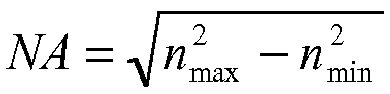
- the numerical aperture NA of the fibre defined by NA n max 2 - n min 2 is less than 0.29.
- Such a fibre can be used in a local area network (LAN).
- LAN local area network
- the invention also proposes an optical transmission system comprising at least one portion of such an optical fibre.
- the system has a data rate greater than or equal to 10 Gb/s up to 100 m.
- the system has a data rate greater than or equal to 10 Gb/s up to 300 m.
- Such a system can be used in a local area network (LAN).
- LAN local area network
- the idea behind the present invention consists of increasing the effective refractive index of the guided modes which guide modes also exist in the standard graded-index multimode fibre.
- a specific multimode fibre architecture is proposed which is unaffected by bending losses for high-speed data transmission (typically 10 GbE).
- Figure 3 is a refractive index profile of an example of a fibre according to the invention.
- the fibre comprises an outer optical cladding the optical index of which is substantially constant over the whole width of the optical cladding.
- the optical index of the cladding is denoted with n cladding .
- the fibre also comprises a core with a radius r 1 , the cladding being in direct contact with the core. This means that the architecture of Figure 3 has no trenches.
- the core of the fibre according to the example of Figure 3 has a radius typical of a multimode fibre.
- the radius of the core can be, for example, a maximum of 36.25 ⁇ m.
- the radius of the core can be comprised between 22 ⁇ m and 28 ⁇ m, and preferably 25 ⁇ m.
- the core has an alpha optical index profile with respect to the outer optical cladding as defined previously.
- the parameter alpha can be comprised between 1.9 and 2.2, preferably between 1.9 and 2.1 and still more advantageously between 2.0 and 2.1.
- the maximum optical index of the core is denoted with n max and the minimum optical index of the core is denoted n min .
- the fibre can in particular be such that the difference between the maximum optical index of the core and the minimum optical index of the core is greater than 10x10 -3 which is expressed by the relationship n max -n min > 10x10 -3 .
- the interface between the core and the cladding is defined by this discontinuous drop in the refractive index.
- the cladding directly surrounds the core without the presence of an intermediate cladding or depressed trench.
- the fibre according to the invention in accordance with the example of Figure 3 differs in that the refractive index of the graded-index core is increased with respect to the optical index of the cladding.
- the fibre according to the invention in accordance with the example of Figure 3 thus has the advantage of having reduced bending losses.
- Such a fibre is moreover compatible with the standard graded-index fibres.
- Figure 4 is a graph on a semi-logarithmic scale which shows the development of the bending losses for two turns as a function of the radius of curvature of the bend imposed on the fibre at a wavelength of 850 nm.
- the development is represented for different values of the difference between the minimum optical index of the core and the index of the cladding, namely 0 (the fibre is then a standard graded-index fibre), 1.10 -3 , 2.10 -3 , 3.10 -3 , 4.10 -3 and 5.10 -3 .
- the multimode optical fibres used for the experiment of Figure 2 all have an effective numerical aperture of 0.2.
- the effective numerical aperture of a multimode fibre with a core of radius 25 ⁇ m amounts to 0.2 whereas the effective numerical aperture for a multimode fibre having a core of radius 31.25 ⁇ m amounts to 0.275.
- the bending losses for a fibre according to the invention are reduced by approximately 30% with respect to a standard graded-index fibre. This shows that the fibre according to the invention exhibits reduced bending losses with respect to a standard graded-index fibre.
- n min -n cladding is 4x10 -3 or 5x10 -3 for which the reductions in bending losses with respect to a standard graded-index fibre are at least 73% or 90%.
- the difference between the minimum optical refractive index of the core and the refractive index of the cladding reduces the extent to which the fibre is affected by bends. It may therefore be advantageous for the difference between the minimum optical refractive index of the core and the refractive index of the cladding to be strictly greater than 2x10 -3 . In such a case, the fibre can exhibit a bending loss of less than 0.1 dB for two turns for a radius of curvature of 15 mm.
- Such a fibre is intended to be used in an optical transmission system. It is therefore interesting to study the compatibility of the multimode fibre according to the invention as depicted in the example of Figure 3 with a standard graded-index fibre as defined previously.
- the increase in the contrast of the refractive index for the fibre according to the example of Figure 3 generally leads to greater linear losses, in particular due to the increase in Rayleigh diffusion and/or absorption.
- the chromatic dispersion of the fibre according to Figure 3 can be greater than for a standard graded-index fibre.
- the numerical aperture of the fibre of Figure 3 is greater than the maximum permitted value.
- the numerical aperture of the fibre according to the example of Figure 3 can in particular be greater than 0.18.
- the numerical aperture can also be less than 0.29.
- the two conditions can moreover be fulfilled by the same fibre according to the example of Figure 3 , in which case the numerical aperture is comprised between 0.18 and 0.29.
- the fibre of Figure 3 does not therefore fulfil the conditions of the standards. This means that additional modes are permitted by the refractive index profile of the fibre according to the example of Figure 3 , the modes not existing in the standard graded-index fibre. Comparison of Figures 5 and 6 makes it possible to illustrate this fact.
- Figure 5 shows the index profile of a standard graded-index fibre. As explained above, this is an ⁇ profile.
- the lower x-axis shows the radius of the fibre, and the y-axis on the left shows the refractive index of the standard graded-index fibre.
- the refractive index profile with respect to the cladding is represented by a black unbroken line.
- the graph also shows the modes which propagate in the fibre by means of dots.
- the y-axis on the right shows the relative effective refractive indices of the propagation modes, i.e. the difference between the effective refractive index of the mode and the refractive index of the cladding.
- a reference called the azimuthal index, shown on the upper x-axis corresponds to each mode. This index is also called the main mode number.
- the modes are placed in groups of visible modes in a horizontal direction of the graph. For example the fibre shown comprises 18 mode groups.
- Figure 6 shows a graph similar to Figure 5 for a fibre according to the example of Figure 3 .
- the lower x-axis similarly shows the radius of the fibre
- the y-axis on the left shows the refractive index of the fibre according to the example of Figure 3 .
- the fibre according to the example of Figure 3 has the same ⁇ profile as the standard graded-index fibre with a value for the difference between the minimum index of the core and the cladding amounting to 10.10-3.
- the graph also shows the modes which propagate in the fibre.
- the y-axis on the right shows the relative effective refractive indices of the propagation modes.
- a reference called the azimuthal index, shown on the upper x-axis corresponds to each mode.
- the fibre shown comprises 33 mode groups. The number of modes in the fibre according to the example of Figure 3 is therefore greater than the number of modes in a standard graded-index fibre.
- the 18 modes have the same azimuthal index and consequently the same shape.
- the modes of a standard graded-index fibre therefore exist in a fibre according to the example of Figure 3 .
- each guided mode of the standard graded-index fibre is coupled with only one mode (the closest from the point of view of shape), and thus each mode group of the standard graded-index fibre is coupled in only the same mode group in the fibre according to the example of Figure 3 .
- the higher order modes in the fibre according to the example of Figure 3 which do not exist in the standard graded-index fibre are not excited because they are orthogonal to all the guided modes of the standard graded-index fibre. This becomes apparent in particular by analyzing the graphs of Figures 7 and 8 .
- Figures 7 and 8 graphically illustrate the efficiency of coupling between the 18 mode groups of the standard graded-index fibre and the 33 mode groups of the fibre according to the example of Figure 3 .
- the two fibres used are the same as the fibres used for Figures 5 and 6 .
- a grey scale is used, a coupling of 1 corresponding to an ideal coupling, without losses between the standard graded-index fibre and the fibre according to the example of Figure 3 and a coupling of 0 corresponding to an absence of coupling.
- Figure 7 is produced under conditions where the two fibres are perfectly centred with respect to each other whereas in the case of Figure 8 , the fibres are shifted 3 ⁇ m in relation to each other.
- a mode group of the standard graded-index fibre has the best coupling with the mode group of the fibre having the same main mode number whether in the perfect alignment ( Figure 7 ) or shifted ( Figure 8 ) configuration.
- the mode groups with a main mode number greater than 18 cannot be excited by a standard graded-index fibre. It is thus shown that the standard graded-index fibre cannot excite additional modes generated in the fibre according to the example of Figure 3 by the overall increase in the refractive index of the core.
- a fibre according to the example of Figure 3 is therefore compatible in combination with a standard graded-index fibre having the same ⁇ profile.
- connection between a fibre according to the example of Figure 3 and a standard graded-index fibre does not mix and does not filter the propagation modes.
- a fibre according to the example of Figure 3 therefore exhibits very good coupling with a standard graded-index fibre.
- the transmission system can moreover comprise a light source with a numerical aperture less than the numerical aperture of a standard graded-index fibre. If such a source is centred in terms of position and angularly, the light originating from the source will be injected into the guided modes which are compatible with the modes of the standard graded-index fibre, which means that the excited modes will have an effective index comprised between the extreme indices of the core of the fibre, i.e. n min and n max .
- Figures 9 and 10 are graphs which illustrate the propagation times for the mode groups respectively of the standard graded-index fibre used for Figures 5 and 7 and of the fibre according to the example of Figure 3 used for Figures 6 and 8 .
- the modal dispersions observed are similar. Therefore, the fibres according to the example of Figure 3 have the same ability to support transmissions at a greater bit rate than the standard graded-index fibres.
- the fibre according to the example of Figure 3 is therefore a graded-index fibre exhibiting reduced bending losses with coupling losses to a standard graded-index fibre which are more limited than in the state of the art.
- the manoeuvrability of the fibre is in particular greatly improved thanks to its exceptional insensitivity to bending losses.
- the fibre of Figure 3 is also compatible with a high-speed transmission.
- the system thus makes it possible to obtain error-free transmissions for a data rate greater than or equal to 10 Gb/s (10 GbE) for a significant distance, up to, for example, 100 m or 300 m.
- optical fibers according to the present invention may be manufactured by drawing from final preforms.
- a final preform may be manufactured by providing a primary preform with an outer overcladding layer (i.e., an overcladding process).
- the outer overcladding layer consists of doped or undoped, natural or synthetic, silica glass. Several methods are available for providing the outer overcladding layer.
- the outer overcladding layer may be provided by depositing and vitrifying natural or synthetic silica particles on the outer periphery of the primary preform under the influence of heat.
- a process is known, for example, from U.S. Patent Nos. 5,522,007 ; 5,194,714 ; 6,269,663 ; and 6,202,447 .
- a primary preform may be overcladded using a silica sleeve tube, which may or may not be doped. This sleeve tube may then be collapsed onto the primary preform.
- an overcladding layer may be applied via an Outside Vapor Deposition (OVD) method.
- ODD Outside Vapor Deposition
- a soot layer is first deposited on the outer periphery of a primary preform, and then the soot layer is vitrified to form glass.
- the primary preforms may be manufactured via outside vapor deposition techniques, such as Outside Vapor Deposition (OVD) and Vapor Axial Deposition (VAD).
- OCVD Outside Vapor Deposition
- VAD Vapor Axial Deposition
- the primary preforms may be manufactured via inside deposition techniques in which glass layers are deposited on the inner surface of a substrate tube of doped or undoped silica glass, such as Modified Chemical Vapor Deposition (MCVD), Furnace Chemical Vapor Deposition (FCVD), and Plasma Chemical Vapor Deposition (PCVD).
- MCVD Modified Chemical Vapor Deposition
- FCVD Furnace Chemical Vapor Deposition
- PCVD Plasma Chemical Vapor Deposition
- the primary preforms are manufactured using a PCVD process, which allows the shape of the central core's gradient refractive index profile to be controlled very precisely.
- the depressed trench may be deposited on the inner surface of a substrate tube as part of the chemical vapor deposition process. More typically, the depressed trench may be manufactured either (i) by using a fluorine-doped substrate tube as the starting point of the internal deposition process for deposition of the gradient refractive index central core or (ii) by sleeving a fluorine-doped silica tube over the gradient refractive index central core, which itself may be produced using an outside deposition process (e.g., OVD or VAD).
- an outside deposition process e.g., OVD or VAD
- a primary preform is manufactured via an inside deposition process using a fluorine-doped substrate tube.
- the resulting tube containing the deposited layers may be sleeved by one or more additional fluorine-doped silica tubes so as to increase the thickness of the depressed trench, or to create a depressed trench having a varying refractive index over its width.
- one or more additional sleeve tubes e.g., fluorine-doped substrate tubes
- the process of sleeving and collapsing is sometimes referred to as jacketing and may be repeated to build several glass layers on the outside of the primary preform.
- the fibre according to the invention can be installed in numerous transmission systems having good compatibility with the other fibres of the system.
- the multimode fibre according to the invention can be used in an Ethernet optical system with an improved bandwidth.
- the fibre can also be used in a local area network (LAN).
- LAN local area network
Landscapes
- Physics & Mathematics (AREA)
- Chemical & Material Sciences (AREA)
- Dispersion Chemistry (AREA)
- General Physics & Mathematics (AREA)
- Optics & Photonics (AREA)
- Optical Couplings Of Light Guides (AREA)
- Optical Communication System (AREA)
- Manufacture, Treatment Of Glass Fibers (AREA)
Abstract
wherein the core has a radius (r1) and an α refractive index profile with a graded index with respect to the cladding, the maximum refractive index of the core being nmax and the minimum refractive index of the core being nmin, in which nmin - ncladding > 2x10⁻³, the fibre exhibiting a bending loss of less than 0.1 dB for two turns for a radius of curvature of 15 mm. The cladding is in direct contact with the core.
Description
- The present invention relates to the field of optical fibre transmissions, and more specifically, to a multimode optical fibre having greatly reduced bending losses for use in high-speed applications.
- In standard fashion, an optical fibre is composed of an optical core having the function of transmitting and optionally amplifying an optical signal, and an outer optical cladding having the function of confining the optical signal within the optical core. To this end, the refractive indices of the optical core ncore and of the outer optical cladding ncladding are such that ncore>ncladding. In the following description where the "core" of the optical fiber is mentioned the optical core is meant, unless otherwise stated; and where the "cladding" of the optical fiber is mentioned, the outer optical cladding is meant, unless otherwise stated; and where "fibre" is stated and optical fibre is meant, unless otherwise stated or otherwise clear from the context.
- The refractive index profile of a fibre denotes the graph associating the refractive index with the radius of the fibre. In standard fashion, the distance to the centre of the fibre is shown on the x-axis, and on the y-axis, the difference is shown between the refractive index of the fibre at radius r and the refractive index of the cladding of the fibre. Generally the refractive index profile is qualified according to its appearance. Thus the index profile is described in terms of a "step", "trapezium", "triangle", or "alpha" for graphs which have step, trapezium, triangle, or graded (α) shapes respectively. These curves are representative of the theoretical or set profile of the fibre, while the manufacturing constraints of the fibre may result in a slightly different profile.
- Two main types of optical fibres exist, multimode fibres and single mode fibres. In a multimode fibre, for a given wavelength, several optical modes are propagated simultaneously along the fibre, whereas in a single mode fibre optical modes of a higher order are strongly attenuated. The typical diameter of a single mode or multimode optical fibre is 125 µm. The core of a multimode fibre typically has a diameter of 50 µm or 62.5 µm, whereas the core of a single-mode fibre generally has a diameter of approximately 6 µm to 9 µm. The multimode optical systems are less expensive than the single mode optical systems, as the sources, connectors, and maintenance are of lower cost.
- Now, in a multimode fibre, the bandwidth is linked to the intermodal dispersion. In fact, the bandwidth results from the difference between the propagation times, or group delay times, of the optical modes along the fibre. In particular, for the same propagation medium (in a step index multimode fibre), the different modes have group delay times which are different. This results in a time lag between the pulses propagating in different radial directions. A time lag between the individual pulses causes a broadening of the resulting light pulse with a risk of this broadening being superimposed onto a following pulse, and therefore reducing the data rate supported by the fibre. The bandwidth is therefore directly linked to the group delay time of the optical modes propagating in the multimode core of the fibre. In order to guarantee a broad bandwidth, it is necessary for the group delay times of all the modes to be identical; i.e. for the intermodal dispersion to be zero, or at least minimized, for a given wavelength.
- In order to reduce the intermodal dispersion in a multimode fibre, it has been proposed to produce graded-index fibres with an "alpha" or α- core profile. Such a fibre has been used for many years and its characteristics have been described in particular in "Multimode theory of graded-core fibres" by D. Gloge et al., Bell system Technical Journal 1973, pp 1563-1578, and summarized in "Comprehensive theory of dispersion in graded-index optical fibers" by G. Yabre, Journal of Lightwave Technology, February 2000, Vol. 18, No. 2, pp 166-177.
- A fibre having a graded-index profile or alpha-index profile - these two terms are equivalent - is a fibre with a graded-index core surrounded by a cladding with a constant optical index. The α index profile follows a power law for parameter α which can be defined by a relationship between the index value n at a certain point as a function of the distance r from this point to the centre of the fibre:

- with α ≥ 1; nmax, the maximum optical index of the core of the multimode fibre; r1, the radius of the core of the multimode fibre; and

where nmin is the minimum refractive index of the multimode core, generally corresponding to the refractive index of the cladding (most often made of natural or synthetic, doped or undoped silica). - A graded-index multimode fibre therefore has a core profile with a rotational symmetry such that in any radial direction the value of the refractive index decreases continuously from the centre of the fibre to its periphery. When a multimode light signal propagates in such a core having a graded index, the different modes experience a different propagation medium, which affects their speed of propagation differently. By an adjustment of the value of the parameter α, it is therefore possible to obtain a group delay time which is virtually equal for all the modes, and therefore a reduced intermodal dispersion. This results in the multimode fibres, having an α index profile as the refractive index profile, having a maximum bandwidth for the communication of data.
- Hereinafter, by the expression "standard graded-index fibre" is meant a fibre with an α optical index profile satisfying international standards and such that the minimum optical refractive index of the core and the refractive index of the cladding are equal. In such a situation, the difference between the minimum optical index of the core and the refractive index of the cladding is strictly less than 1x10⁻³, or even zero. Multimode fibres have been the subject of international standardization under standard ITU-T G.651.1 which in particular defines criteria for bandwidths, numerical aperture, core diameter; which relate to the requirements for compatibility between fibres. The standard OM3 has been adopted to satisfy high-speed applications (greater than 1GbE) over long distances (greater than 300 m). With the development of high-speed applications the average core diameter has been reduced from 62.5 µm to 50 µm.
- Such multimode fibres with a large bandwidth are in particular intended to be used for short distances in a local area network (LAN) in which they might be subjected to accidental bending. Such bends modify the mode power distribution and can consequently modify the bandwidth of the fibre.
- It is therefore interesting to design a multimode fibre which is unaffected by bends even for radii of curvature of less than 10 mm. Such a fibre must be compatible with the standard graded-index fibres and allow high-speed transmission of 10 Gb/s in 10GbE systems for example (GbE for Gigabit Ethernet)
- One solution to such a problem could consist in adjusting the conditions for injection of the light originating from a light source into the fibre considered. As all the modes are affected differently by bends, it would be sufficient to modify the injection conditions so that the only modes in which a coupling exists with the injected light are modes unaffected by bends.
- However, in practice, the source and the coupling device between the source and the fibre impose launch conditions preventing the adjustment of the injection conditions.
- Moreover, restricting the coupling to the lowest order modes involves a loss of power coupling efficiency.
- Such a phenomenon can be accompanied by an increase in the impact of the mode partition noise on the light transmitted in the fibre. The increase appears when laser sources are used in combination with the fibre and in particular if VCSEL (Vertical Cavity Surface Emitting Laser) diodes allowing a transmission of 10 GbE are used. The mode partition noise corresponds to "jitter" of the signal phase due to the combined effects of changing the main mode of the optical source ("mode hopping") and intramodal distortions in the fibre. The change of the main mode is a sudden jump in the optical frequency of the optical source, associated with transitions between the different modes of the resonator. Thus, the change of the main mode of the optical source leads to random modifications in the wavelength affecting the group velocity and therefore the propagation time. Over the length of the fibre, the cumulative effect of this variation of the group velocity is to induce phase jitter, i.e. mode partition noise.
-
EP 1 164 393 A1JP-A-2002 318315 - It is also known to apply additional bends to the multimode fibre. Thus an access network with a multimode fibre in which part of the multimode fibre is bent is known from the document
EP-A-1 727 302 . This results in a reduction in transmission loss due to a bend in the remaining network. In the same way as for the solution mentioned previously for modifying the injection conditions, the application of additional bends to a multimode fibre can also induce losses in the power coupling efficiency with, if appropriate, an increase in the impact of the mode partition noise if VCSELS allowing a 10 GbE transmission are used. - Another solution is a dedicated fibre architecture i.e. a specific optical index profile. It is known to reduce the bending losses of a graded-index multimode fibre by adding a depressed trench between the core and the cladding. The documents
WO-A-2008085851 andUS-A-20080166094 thus describe a graded-index core surrounded by a depressed trench. The graded-index fibre's resistance to bending losses is thus increased. - Such a solution poses several problems, in particular with respect to manufacture. Typically, the central core, i.e. the "alpha" core, the cladding and part of the external protective cladding are obtained by chemical vapour deposition (CVD) in a silica tube. The cladding or external protective cladding is constituted by the tube and the overcladding of the tube generally with natural or doped silica. The overcladding may be obtained by any other deposition technique (VAD or OVD). However, the implementation of the solutions of the documents
WO-A-2008085851 andUS-A-20080166094 requires a broad deposition zone, which is not optimal from the point of view of the cost of chemical vapour deposition techniques. In fact, this leads to the production of a smaller length of fibre per core rod. - Moreover the addition of a depressed trench results in the appearance of supplementary propagation modes known as leaky modes. The leaky modes have effective refractive indices which are lower than those of the guided modes. This leads to an increase in the numerical aperture in the graded-index fibres comprising a depressed trench, in comparison with the graded-index fibres without a depressed trench. Such a difference in numerical aperture can lead to losses during connections within a system comprising graded-index fibres with a depressed trench and graded-index fibres without a depressed trench.
- A need therefore exists for a graded-index fibre having reduced bending losses with coupling losses to a standard graded-index fibre which are more limited than in the state of the art.
- For this purpose, the invention proposes a multimode optical fibre comprising a cladding, optionally this is an outer optical cladding, with an optical index nodding and a central core having a radius r1 and an optical index profile with a graded index of parameter α, also called an α optical index profile with a graded index. The maximum optical index of the core is nmax and the minimum optical index of the core is nmin. The fibre is such that the relationship nmin-ncladding > 2x10⁻³ is satisfied and exhibits a bending loss less than 0.1 dB per two turns for a radius of curvature of 15 mm. The cladding, optionally this is the outer optical cladding is in direct contact with the core.
- According to the present invention it is preferred that the outer optical cladding directly surrounds the "alpha" core. However, it is possible that an inner cladding having a refractive index that is preferably close to the refractive index of the outer optical cladding could be inserted between the "alpha" core and the outer optical cladding.
- According to an embodiment, the fibre is such that nmax-nmin> 10x10-3.
- According to another embodiment example, the radius of the central core r1 is comprised between 22 µm and 28 µm.
- The present invention relates to glass-based optical fibers.
- According to another embodiment example, the parameter α is comprised between 1.9 and 2.2, preferably between 1.9 and 2.1 and more advantageously between 2.0 and 2.1.
- According to another embodiment example, the numerical aperture (NA) of the fibre defined by

- According to yet another embodiment example, the numerical aperture NA of the fibre defined by
- Such a fibre can be used in a local area network (LAN).
- The invention also proposes an optical transmission system comprising at least one portion of such an optical fibre.
- According to an embodiment the system has a data rate greater than or equal to 10 Gb/s up to 100 m.
- According to another embodiment the system has a data rate greater than or equal to 10 Gb/s up to 300 m.
- Such a system can be used in a local area network (LAN).
- Other characteristics and advantages of the invention will become apparent on reading the following detailed description of the embodiments of the invention, given by way of example only and with reference to the drawings which show:
-
Figure 1 , a graph of bending losses of a fibre as a function of the effective refractive index difference at a wavelength of 1300 nm; -
Figure 2 , a graph of bending losses of a fibre as a function of the effective refractive index difference at a wavelength of 850 nm; -
Figure 3 , an index profile of an example of a fibre according to the invention. -
Figure 4 , a graph of the development of the bending losses for two turns as a function of the radius of curvature of the bending imposed on a fibre; -
Figure 5 , an index profile of a standard graded-index fibre and the modes propagating in the fibre; -
Figure 6 , an index profile of an example of a graded-index fibre according to the invention and the modes propagating in the fibre; -
Figure 7 , a graph of the efficiency of coupling between the mode groups of the standard graded-index fibre and the mode groups of the graded-index fibre according to the example ofFigure 3 ; -
Figure 8 , a graph of the efficiency of coupling between the mode groups of the standard graded-index fibre and the mode groups of the graded-index fibre according to the example ofFigure 3 ; -
Figure 9 , a graph showing the propagation delays of the modes as a function of the main mode number for a standard graded-index fibre and -
Figure 10 a graph showing the propagation delays of the modes as a function of the main mode number for a multimode graded-index fibre according to the invention. - It is known that the bending losses in the modes of a multimode fibre depend mainly on the effective mode index. This is in particular illustrated by
Figures 1 and 2 which are graphs of bending losses of a fibre as a function of the effective index difference of the mode considered respectively at 1300 nm and 850 nm. The effective index difference is the difference between the effective refractive index of the mode and the refractive index of the cladding. Each of the two experiments is carried out for two numerical apertures (ON) of the fibre: 0.2 and 0.185 and a radius of curvature for the bending imposed on the fibre of 15 mm. In the examples ofFigures 2 and3 , the modes affected by bends have an effective index difference of 4x10⁻³. The extent to which a multimode fibre is affected is therefore directly linked to the ratio of the number of modes unaffected by bends to the total number of modes. - The idea behind the present invention consists of increasing the effective refractive index of the guided modes which guide modes also exist in the standard graded-index multimode fibre. For this purpose, a specific multimode fibre architecture is proposed which is unaffected by bending losses for high-speed data transmission (typically 10 GbE).
- Such an architecture is shown in
Figure 3. Figure 3 is a refractive index profile of an example of a fibre according to the invention. The fibre comprises an outer optical cladding the optical index of which is substantially constant over the whole width of the optical cladding. The optical index of the cladding is denoted with ncladding. The fibre also comprises a core with a radius r1, the cladding being in direct contact with the core. This means that the architecture ofFigure 3 has no trenches. The core of the fibre according to the example ofFigure 3 has a radius typical of a multimode fibre. The radius of the core can be, for example, a maximum of 36.25 µm. Preferably, the radius of the core can be comprised between 22 µm and 28 µm, and preferably 25 µm. - The core has an alpha optical index profile with respect to the outer optical cladding as defined previously. The parameter alpha can be comprised between 1.9 and 2.2, preferably between 1.9 and 2.1 and still more advantageously between 2.0 and 2.1. The maximum optical index of the core is denoted with nmax and the minimum optical index of the core is denoted nmin. The fibre can in particular be such that the difference between the maximum optical index of the core and the minimum optical index of the core is greater than 10x10-3 which is expressed by the relationship nmax-nmin > 10x10-3.
- The fibre is characterized by the fact that the minimum optical index of the core is strictly greater than the index of the cladding. This can be expressed mathematically by the fact that the difference between the minimum optical index of the core and the index of the cladding is a strictly positive quantity, which means that nmin - ncladding >0. This means that there is a distinct of discontinuous drop in the refractive index at the value of r = r1, going from a refractive index value of nmin to a refractive index value of ncladding. This drop controls the modal dispersion, which modal dispersion must be controlled to guarantee modal bandwith compatibility with data communication. The interface between the core and the cladding is defined by this discontinuous drop in the refractive index. The cladding directly surrounds the core without the presence of an intermediate cladding or depressed trench.
- With respect to a standard graded-index fibre, the fibre according to the invention in accordance with the example of
Figure 3 differs in that the refractive index of the graded-index core is increased with respect to the optical index of the cladding. The fibre according to the invention in accordance with the example ofFigure 3 thus has the advantage of having reduced bending losses. Such a fibre is moreover compatible with the standard graded-index fibres. The advantages of the fibre according to the example ofFigure 3 are explained in greater detail below. - The reduction in bending losses becomes more clearly apparent on considering
Figure 4. Figure 4 is a graph on a semi-logarithmic scale which shows the development of the bending losses for two turns as a function of the radius of curvature of the bend imposed on the fibre at a wavelength of 850 nm. The development is represented for different values of the difference between the minimum optical index of the core and the index of the cladding, namely 0 (the fibre is then a standard graded-index fibre), 1.10-3, 2.10-3, 3.10-3, 4.10-3 and 5.10-3. - The multimode optical fibres used for the experiment of
Figure 2 all have an effective numerical aperture of 0.2. The effective numerical aperture NA of a fibre is defined by the expression:
where neff,min and neff,max are respectively the minimum and maximum effective refractive indices of the modes comprised in the signal measured at the fibre output under OFL (overfilled launch) conditions. Under such conditions, the excitation of the signal at the fibre input is uniform over all the propagation modes. This assumes the use of a light source exhibiting uniform excitation over the entire radial surface of the fibre, for example a laser diode or LED (Light Emitting Diode). - However, a good approximation of the effective numerical aperture is obtained with the square root of the difference in the squares of the refractive indices of the core of the fibre. This can also be written in the form of the relationship:

where nmax and nmin are respectively the maximum and minimum refractive indices of the fibre profile. The approximate formula is used hereafter. - For the case of a standard graded-index fibre, the effective numerical aperture of a multimode fibre with a core of
radius 25 µm amounts to 0.2 whereas the effective numerical aperture for a multimode fibre having a core of radius 31.25 µm amounts to 0.275. - In the experiment of
Figure 4 , all the guided modes in the fibre have an effective index greater than nmin and are also excited. As explained below during the description of a system with a portion of fibre according to the example ofFigure 3 , this is possible by coupling the fibre according to the example ofFigure 3 with a standard graded-index multimode fibre under OFL conditions or with a source the numerical aperture of which is less than the effective numerical aperture of the fibre according to the example ofFigure 3 . - At a constant effective numerical aperture, the greater the difference between the minimum optical index of the core and the index of the cladding for the fibre the greater the reduction in bending loss for the fibre. By way of illustration, for a radius of curvature of 10 mm, the bending losses for a fibre according to the invention are reduced by approximately 30% with respect to a standard graded-index fibre. This shows that the fibre according to the invention exhibits reduced bending losses with respect to a standard graded-index fibre.
- The effect of reducing the bending losses is yet more marked for the fibres according to the invention so that nmin-ncladding is 4x10⁻³ or 5x10⁻³ for which the reductions in bending losses with respect to a standard graded-index fibre are at least 73% or 90%.
- Thus, increasing the value of the difference between the minimum optical refractive index of the core and the refractive index of the cladding with a constant effective numerical aperture reduces the extent to which the fibre is affected by bends. It may therefore be advantageous for the difference between the minimum optical refractive index of the core and the refractive index of the cladding to be strictly greater than 2x10⁻³. In such a case, the fibre can exhibit a bending loss of less than 0.1 dB for two turns for a radius of curvature of 15 mm.
- Such a fibre is intended to be used in an optical transmission system. It is therefore interesting to study the compatibility of the multimode fibre according to the invention as depicted in the example of
Figure 3 with a standard graded-index fibre as defined previously. - However, the increase in the contrast of the refractive index for the fibre according to the example of
Figure 3 generally leads to greater linear losses, in particular due to the increase in Rayleigh diffusion and/or absorption. Moreover, the chromatic dispersion of the fibre according toFigure 3 can be greater than for a standard graded-index fibre. Moreover, the numerical aperture of the fibre ofFigure 3 is greater than the maximum permitted value. The numerical aperture of the fibre according to the example ofFigure 3 can in particular be greater than 0.18. The numerical aperture can also be less than 0.29. The two conditions can moreover be fulfilled by the same fibre according to the example ofFigure 3 , in which case the numerical aperture is comprised between 0.18 and 0.29. - The fibre of
Figure 3 does not therefore fulfil the conditions of the standards. This means that additional modes are permitted by the refractive index profile of the fibre according to the example ofFigure 3 , the modes not existing in the standard graded-index fibre. Comparison ofFigures 5 and 6 makes it possible to illustrate this fact. -
Figure 5 shows the index profile of a standard graded-index fibre. As explained above, this is an α profile. The lower x-axis shows the radius of the fibre, and the y-axis on the left shows the refractive index of the standard graded-index fibre. The refractive index profile with respect to the cladding is represented by a black unbroken line. The graph also shows the modes which propagate in the fibre by means of dots. The y-axis on the right shows the relative effective refractive indices of the propagation modes, i.e. the difference between the effective refractive index of the mode and the refractive index of the cladding. A reference called the azimuthal index, shown on the upper x-axis, corresponds to each mode. This index is also called the main mode number. Typically the modes are placed in groups of visible modes in a horizontal direction of the graph. For example the fibre shown comprises 18 mode groups. -
Figure 6 shows a graph similar toFigure 5 for a fibre according to the example ofFigure 3 . Thus, the lower x-axis similarly shows the radius of the fibre, and the y-axis on the left shows the refractive index of the fibre according to the example ofFigure 3 . The fibre according to the example ofFigure 3 has the same α profile as the standard graded-index fibre with a value for the difference between the minimum index of the core and the cladding amounting to 10.10-3. The graph also shows the modes which propagate in the fibre. The y-axis on the right shows the relative effective refractive indices of the propagation modes. A reference called the azimuthal index, shown on the upper x-axis, corresponds to each mode. The fibre shown comprises 33 mode groups. The number of modes in the fibre according to the example ofFigure 3 is therefore greater than the number of modes in a standard graded-index fibre. - However, among these 33 mode groups, only 18 mode groups have an effective index greater than the minimum optical index of the core. These are the modes which are situated above the dotted line in
Figure 6 . The 18 lower order modes of the fibre according to the example ofFigure 3 are as numerous as those of the standard graded-index fibre. The 18 modes have a higher effective index than the 18 modes of the corresponding standard graded-index fibre which explains their better resistance to bending losses. - Nevertheless, the 18 modes have the same azimuthal index and consequently the same shape. The modes of a standard graded-index fibre therefore exist in a fibre according to the example of
Figure 3 . As a result, when the fibre according to the example ofFigure 3 is coupled with a standard graded-index fibre, each guided mode of the standard graded-index fibre is coupled with only one mode (the closest from the point of view of shape), and thus each mode group of the standard graded-index fibre is coupled in only the same mode group in the fibre according to the example ofFigure 3 . The higher order modes in the fibre according to the example ofFigure 3 which do not exist in the standard graded-index fibre are not excited because they are orthogonal to all the guided modes of the standard graded-index fibre. This becomes apparent in particular by analyzing the graphs ofFigures 7 and 8 . -
Figures 7 and 8 graphically illustrate the efficiency of coupling between the 18 mode groups of the standard graded-index fibre and the 33 mode groups of the fibre according to the example ofFigure 3 . The two fibres used are the same as the fibres used forFigures 5 and 6 . A grey scale is used, a coupling of 1 corresponding to an ideal coupling, without losses between the standard graded-index fibre and the fibre according to the example ofFigure 3 and a coupling of 0 corresponding to an absence of coupling.Figure 7 is produced under conditions where the two fibres are perfectly centred with respect to each other whereas in the case ofFigure 8 , the fibres are shifted 3 µm in relation to each other. As noted previously, a mode group of the standard graded-index fibre has the best coupling with the mode group of the fibre having the same main mode number whether in the perfect alignment (Figure 7 ) or shifted (Figure 8 ) configuration. As a result the mode groups with a main mode number greater than 18 cannot be excited by a standard graded-index fibre. It is thus shown that the standard graded-index fibre cannot excite additional modes generated in the fibre according to the example ofFigure 3 by the overall increase in the refractive index of the core. A fibre according to the example ofFigure 3 is therefore compatible in combination with a standard graded-index fibre having the same α profile. This means that a connection between a fibre according to the example ofFigure 3 and a standard graded-index fibre does not mix and does not filter the propagation modes. A fibre according to the example ofFigure 3 therefore exhibits very good coupling with a standard graded-index fibre. - From this observation, it follows that the transmission system can moreover comprise a light source with a numerical aperture less than the numerical aperture of a standard graded-index fibre. If such a source is centred in terms of position and angularly, the light originating from the source will be injected into the guided modes which are compatible with the modes of the standard graded-index fibre, which means that the excited modes will have an effective index comprised between the extreme indices of the core of the fibre, i.e. nmin and nmax.
- When it would be preferable to use a source so that the numerical aperture is less than the numerical aperture of a standard graded-index fibre, additional modes are generated. It is then possible to design a specific cable and/or apply additional bends as described in the document
EP-A-1 727 302 in order to eliminate only the additional modes created. -
Figures 9 and 10 are graphs which illustrate the propagation times for the mode groups respectively of the standard graded-index fibre used forFigures 5 and7 and of the fibre according to the example ofFigure 3 used forFigures 6 and8 . The modal dispersions observed are similar. Therefore, the fibres according to the example ofFigure 3 have the same ability to support transmissions at a greater bit rate than the standard graded-index fibres. - The fibre according to the example of
Figure 3 is therefore a graded-index fibre exhibiting reduced bending losses with coupling losses to a standard graded-index fibre which are more limited than in the state of the art. The manoeuvrability of the fibre is in particular greatly improved thanks to its exceptional insensitivity to bending losses. - The fibre of
Figure 3 is also compatible with a high-speed transmission. The system thus makes it possible to obtain error-free transmissions for a data rate greater than or equal to 10 Gb/s (10 GbE) for a significant distance, up to, for example, 100 m or 300 m. - The optical fibers according to the present invention may be manufactured by drawing from final preforms.
- A final preform may be manufactured by providing a primary preform with an outer overcladding layer (i.e., an overcladding process). The outer overcladding layer consists of doped or undoped, natural or synthetic, silica glass. Several methods are available for providing the outer overcladding layer.
- In a first example of a method, the outer overcladding layer may be provided by depositing and vitrifying natural or synthetic silica particles on the outer periphery of the primary preform under the influence of heat. Such a process is known, for example, from
U.S. Patent Nos. 5,522,007 ;5,194,714 ;6,269,663 ; and6,202,447 . - In another example of a method, a primary preform may be overcladded using a silica sleeve tube, which may or may not be doped. This sleeve tube may then be collapsed onto the primary preform.
- In yet another example of a method, an overcladding layer may be applied via an Outside Vapor Deposition (OVD) method. Here, a soot layer is first deposited on the outer periphery of a primary preform, and then the soot layer is vitrified to form glass.
- The primary preforms may be manufactured via outside vapor deposition techniques, such as Outside Vapor Deposition (OVD) and Vapor Axial Deposition (VAD). Alternatively, the primary preforms may be manufactured via inside deposition techniques in which glass layers are deposited on the inner surface of a substrate tube of doped or undoped silica glass, such as Modified Chemical Vapor Deposition (MCVD), Furnace Chemical Vapor Deposition (FCVD), and Plasma Chemical Vapor Deposition (PCVD).
- In an example of an embodiment, the primary preforms are manufactured using a PCVD process, which allows the shape of the central core's gradient refractive index profile to be controlled very precisely.
- The depressed trench may be deposited on the inner surface of a substrate tube as part of the chemical vapor deposition process. More typically, the depressed trench may be manufactured either (i) by using a fluorine-doped substrate tube as the starting point of the internal deposition process for deposition of the gradient refractive index central core or (ii) by sleeving a fluorine-doped silica tube over the gradient refractive index central core, which itself may be produced using an outside deposition process (e.g., OVD or VAD).
- In yet another example of an embodiment, a primary preform is manufactured via an inside deposition process using a fluorine-doped substrate tube. The resulting tube containing the deposited layers may be sleeved by one or more additional fluorine-doped silica tubes so as to increase the thickness of the depressed trench, or to create a depressed trench having a varying refractive index over its width. Although not required, one or more additional sleeve tubes (e.g., fluorine-doped substrate tubes) may be collapsed onto the primary preform before an overcladding step is carried out. The process of sleeving and collapsing is sometimes referred to as jacketing and may be repeated to build several glass layers on the outside of the primary preform.
- Of course, the present invention is not limited to the embodiments described by way of example. The fibre according to the invention can be installed in numerous transmission systems having good compatibility with the other fibres of the system. The multimode fibre according to the invention can be used in an Ethernet optical system with an improved bandwidth. The fibre can also be used in a local area network (LAN).
- The present invention is recited in the claims that follow.
Claims (12)
- A glass-based multimode optical fibre comprising, from the centre to the periphery an optical core and a cladding having a refractive index defined by ncladding,- wherein the core has a radius (r1) and an α refractive index profile with a graded index with respect to the cladding, wherein the maximum refractive index of the core is defined by nmax and the minimum refractive index of the core is defined by nmin,in which nmin - ncladding > 2x10⁻³, the fibre exhibiting a bending loss of less than 0.1 dB for two turns for a radius of curvature of 15 mm and the cladding being in direct contact with the core.
- A glass-based multimode optical fibre comprising, from the centre to the periphery an optical core and an outer optical cladding having a refractive index defined by ncladding,- wherein the core has a radius (r1) and an α refractive index profile with a graded index with respect to the outer optical cladding, wherein the maximum refractive index of the core is defined by nmax and the minimum refractive index of the core is defined by nmin,
in which nmin - ncladding > 2x10⁻³, the fibre exhibiting a bending loss of less than 0.1 dB for two turns for a radius of curvature of 15 mm and the outer optical cladding being in direct contact with the core. - The fibre according to claim 1 or claim 2, in which nmax-nmin > 10x10-3.
- The fibre according to any one of claims 1-3, in which r1 is comprised between 22 µm and 28 µm.
- The fibre according to any one of claims 1-4, in which the parameter α of the refractive index profile of the core is comprised between 1.9 and 2.2, preferably between 1.9 and 2.1 and more advantageously between 2.0 and 2.1.
- The fibre according to any one of claims 1-4, in which the numerical aperture NA of the fibre defined by

- The fibre according to any one of claims 1-6, in which the numerical aperture NA of the fibre defined by

- Optical transmission system comprising at least one portion of the multimode optical fibre according to any one of claims 1 to 7.
- System according to claim 8 having a data rate greater than or equal to 10 Gb/s up to 100 m.
- System according to claim 8 having a data rate greater than or equal to 10 Gb/s up to 300 m.
- Use of the multimode optical fibre according to any one of claims 1-7 in a local area network (LAN).
- Use of the optical transmission system according to any one of claims 8-10 in a local area network (LAN).
Applications Claiming Priority (2)
| Application Number | Priority Date | Filing Date | Title |
|---|---|---|---|
| FR0904447A FR2950156B1 (en) | 2009-09-17 | 2009-09-17 | MULTIMODE OPTIC FIBER |
| US24362609P | 2009-09-18 | 2009-09-18 |
Publications (3)
| Publication Number | Publication Date |
|---|---|
| EP2299303A2 true EP2299303A2 (en) | 2011-03-23 |
| EP2299303A3 EP2299303A3 (en) | 2011-07-27 |
| EP2299303B1 EP2299303B1 (en) | 2017-12-20 |
Family
ID=42173771
Family Applications (1)
| Application Number | Title | Priority Date | Filing Date |
|---|---|---|---|
| EP10176645.9A Active EP2299303B1 (en) | 2009-09-17 | 2010-09-14 | Multimode optical fibre with reduced bending losses |
Country Status (6)
| Country | Link |
|---|---|
| US (1) | US8340488B2 (en) |
| EP (1) | EP2299303B1 (en) |
| CN (1) | CN102073097B (en) |
| DK (1) | DK2299303T3 (en) |
| ES (1) | ES2659373T3 (en) |
| FR (1) | FR2950156B1 (en) |
Cited By (8)
| Publication number | Priority date | Publication date | Assignee | Title |
|---|---|---|---|---|
| US8340488B2 (en) | 2009-09-17 | 2012-12-25 | Draka Comteq, B.V. | Multimode optical fiber |
| US8406593B2 (en) | 2009-12-03 | 2013-03-26 | Draka Comteq B.V. | Multimode optical fiber with low bending losses and reduced cladding effect |
| US8428410B2 (en) | 2009-12-03 | 2013-04-23 | Draka Comteq B.V. | High-bandwidth multimode optical fiber having reduced bending losses |
| US8483535B2 (en) | 2009-11-25 | 2013-07-09 | Draka Comteq B.V. | High-bandwidth, dual-trench-assisted multimode optical fiber |
| US8565568B2 (en) | 2010-03-02 | 2013-10-22 | Draka Comteq, B.V. | Broad-bandwidth multimode optical fiber having reduced bending losses |
| US9014525B2 (en) | 2009-09-09 | 2015-04-21 | Draka Comteq, B.V. | Trench-assisted multimode optical fiber |
| KR20150067119A (en) * | 2012-10-11 | 2015-06-17 | 드라카 콤텍 비.브이. | High bandwidth multimode optical fiber optimized for multimode and single-mode transmissions |
| EP2362251B1 (en) * | 2010-02-22 | 2023-04-26 | OFS Fitel, LLC | Optical fibers with truncated cores |
Families Citing this family (58)
| Publication number | Priority date | Publication date | Assignee | Title |
|---|---|---|---|---|
| NL1024015C2 (en) | 2003-07-28 | 2005-02-01 | Draka Fibre Technology Bv | Multimode optical fiber provided with a refractive index profile, optical communication system using this and method for manufacturing such a fiber. |
| FR2922657B1 (en) * | 2007-10-23 | 2010-02-12 | Draka Comteq France | MULTIMODE FIBER. |
| US8467650B2 (en) | 2007-11-09 | 2013-06-18 | Draka Comteq, B.V. | High-fiber-density optical-fiber cable |
| FR2932932B1 (en) * | 2008-06-23 | 2010-08-13 | Draka Comteq France Sa | MULTIPLEX WAVE LENGTH OPTIC SYSTEM WITH MULTIMODE OPTIC FIBERS |
| FR2933779B1 (en) | 2008-07-08 | 2010-08-27 | Draka Comteq France | MULTIMODE OPTIC FIBERS |
| WO2010077132A1 (en) | 2008-12-31 | 2010-07-08 | Draka Comteq B.V. | Uvled apparatus for curing glass-fiber coatings |
| FR2940839B1 (en) | 2009-01-08 | 2012-09-14 | Draka Comteq France | INDEX GRADIENT MULTIMODAL OPTICAL FIBER, METHODS FOR CHARACTERIZATION AND MANUFACTURE OF SUCH A FIBER |
| FR2946436B1 (en) | 2009-06-05 | 2011-12-09 | Draka Comteq France | MULTIMODE OPTICAL FIBER WITH LARGE BANDWIDTH WITH AN OPTIMIZED HEAT-SLEEVE INTERFACE |
| FR2953029B1 (en) | 2009-11-25 | 2011-11-18 | Draka Comteq France | MULTIMODE OPTICAL FIBER WITH LARGE BANDWIDTH WITH AN OPTIMIZED HEAT-SLEEVE INTERFACE |
| FR2949870B1 (en) | 2009-09-09 | 2011-12-16 | Draka Compteq France | MULTIMODE OPTICAL FIBER HAVING IMPROVED BENDING LOSSES |
| FR2950443B1 (en) * | 2009-09-22 | 2011-11-18 | Draka Comteq France | OPTICAL FIBER FOR SUM FREQUENCY GENERATION AND METHOD FOR MANUFACTURING THE SAME |
| US8805143B2 (en) | 2009-10-19 | 2014-08-12 | Draka Comteq, B.V. | Optical-fiber cable having high fiber count and high fiber density |
| FR2952634B1 (en) * | 2009-11-13 | 2011-12-16 | Draka Comteq France | RARE EARTH DOPED SILICA FIBER WITH LOW DIGITAL OPENING |
| DK2352047T3 (en) | 2010-02-01 | 2019-11-11 | Draka Comteq Bv | Non-zero dispersion-switched optical fiber with a large effective area |
| EP3399357B1 (en) | 2010-02-01 | 2024-12-11 | Draka Comteq B.V. | Non-zero dispersion shifted optical fiber having a short cutoff wavelength |
| EP2369379B1 (en) | 2010-03-17 | 2015-05-06 | Draka Comteq B.V. | Fibre optique monomode ayant des pertes par courbures réduites |
| US8693830B2 (en) | 2010-04-28 | 2014-04-08 | Draka Comteq, B.V. | Data-center cable |
| PT2390700T (en) | 2010-05-03 | 2016-10-19 | Draka Comteq Bv | PACKAGED OPTICAL FIBER CABLES |
| DK2388239T3 (en) | 2010-05-20 | 2017-04-24 | Draka Comteq Bv | Curing apparatus using angled UV LEDs |
| US8625947B1 (en) | 2010-05-28 | 2014-01-07 | Draka Comteq, B.V. | Low-smoke and flame-retardant fiber optic cables |
| US8871311B2 (en) | 2010-06-03 | 2014-10-28 | Draka Comteq, B.V. | Curing method employing UV sources that emit differing ranges of UV radiation |
| FR2962230B1 (en) | 2010-07-02 | 2012-07-27 | Draka Comteq France | OPTICAL FIBER MONOMODE |
| US8682123B2 (en) | 2010-07-15 | 2014-03-25 | Draka Comteq, B.V. | Adhesively coupled optical fibers and enclosing tape |
| EP2418183B1 (en) | 2010-08-10 | 2018-07-25 | Draka Comteq B.V. | Method for curing coated glass fibres providing increased UVLED intensitiy |
| US8571369B2 (en) | 2010-09-03 | 2013-10-29 | Draka Comteq B.V. | Optical-fiber module having improved accessibility |
| FR2966256B1 (en) | 2010-10-18 | 2012-11-16 | Draka Comteq France | MULTIMODE OPTICAL FIBER INSENSITIVE TO LOSSES BY |
| US8824845B1 (en) | 2010-12-03 | 2014-09-02 | Draka Comteq, B.V. | Buffer tubes having reduced stress whitening |
| DK2482106T5 (en) | 2011-01-31 | 2014-09-22 | Draka Comteq Bv | Multi-mode fiber |
| FR2971061B1 (en) | 2011-01-31 | 2013-02-08 | Draka Comteq France | BROAD BANDWIDTH OPTICAL FIBER WITH LOW CURB LOSSES |
| PT2678728T (en) | 2011-02-21 | 2018-07-05 | Draka Comteq Bv | Fiber Optic Interconnect Cable |
| EP2495589A1 (en) | 2011-03-04 | 2012-09-05 | Draka Comteq B.V. | Rare earth doped amplifying optical fiber for compact devices and method of manufacturing thereof |
| EP2503368A1 (en) | 2011-03-24 | 2012-09-26 | Draka Comteq B.V. | Multimode optical fiber with improved bend resistance |
| EP2506044A1 (en) | 2011-03-29 | 2012-10-03 | Draka Comteq B.V. | Multimode optical fiber |
| EP2518546B1 (en) | 2011-04-27 | 2018-06-20 | Draka Comteq B.V. | High-bandwidth, radiation-resistant multimode optical fiber |
| ES2438173T3 (en) | 2011-05-27 | 2014-01-16 | Draka Comteq Bv | Single mode fiber optic |
| EP2533082B1 (en) | 2011-06-09 | 2013-12-25 | Draka Comteq BV | Single mode optical fiber |
| DK2541292T3 (en) | 2011-07-01 | 2014-12-01 | Draka Comteq Bv | A multimode optical fiber |
| US8565566B2 (en) | 2011-10-05 | 2013-10-22 | Sumitomo Electric Industries, Ltd. | Multi-mode optical fiber |
| EP2584340A1 (en) | 2011-10-20 | 2013-04-24 | Draka Comteq BV | Hydrogen sensing fiber and hydrogen sensor |
| NL2007831C2 (en) | 2011-11-21 | 2013-05-23 | Draka Comteq Bv | Apparatus and method for carrying out a pcvd deposition process. |
| US8565567B2 (en) | 2011-11-23 | 2013-10-22 | Sumitomo Electric Industries, Ltd. | Multi-mode optical fiber |
| US8929701B2 (en) | 2012-02-15 | 2015-01-06 | Draka Comteq, B.V. | Loose-tube optical-fiber cable |
| WO2013160714A1 (en) | 2012-04-27 | 2013-10-31 | Draka Comteq Bv | Hybrid single and multimode optical fiber for a home network |
| US9036137B2 (en) * | 2012-05-07 | 2015-05-19 | Fluke Corporation | Optical light source with controlled launch conditions |
| US8768130B1 (en) | 2013-02-28 | 2014-07-01 | Sumitomo Electric Industries, Ltd. | Multimode optical fiber |
| US9188754B1 (en) | 2013-03-15 | 2015-11-17 | Draka Comteq, B.V. | Method for manufacturing an optical-fiber buffer tube |
| NL2011075C2 (en) | 2013-07-01 | 2015-01-05 | Draka Comteq Bv | Pcvd process with removal of substrate tube. |
| CN105899982B (en) * | 2013-12-20 | 2019-11-22 | 德拉克通信科技公司 | Single-mode fiber with trapezoidal core exhibiting reduced loss |
| US9678270B2 (en) * | 2014-02-28 | 2017-06-13 | Draka Comteq, B.V. | Multimode optical fiber with high bandwidth over an extended wavelength range, and corresponding multimode optical system |
| US9519101B2 (en) * | 2014-04-29 | 2016-12-13 | Corning Incorporated | Few moded optical fiber and system incorporating such |
| JP6998311B2 (en) * | 2016-02-05 | 2022-02-04 | ニューファーン | Fiber optic system |
| EP3488274B1 (en) * | 2016-07-20 | 2023-05-03 | University of Rochester | Lma fibers for suppression of thermal mode instability |
| PL3729151T3 (en) | 2017-12-21 | 2022-07-25 | Draka Comteq France | Bending-loss insensitive single mode fibre, with a shallow trench, and corresponding optical system |
| RU2688897C9 (en) * | 2018-06-28 | 2019-07-03 | Общество с ограниченной ответственностью "Сарансккабель-Оптика" | Optical ground wire cable |
| CN113093328B (en) * | 2021-03-15 | 2023-03-24 | 武汉光谷航天三江激光产业技术研究院有限公司 | Gain optical fiber with axial fiber core numerical aperture change, sleeve and preparation method thereof |
| US12013305B2 (en) * | 2021-08-09 | 2024-06-18 | Fluke Corporation | Modal launch condition using bend-insensitive multimode fiber |
| CN116413860A (en) * | 2021-12-29 | 2023-07-11 | 上海交通大学 | Multi-channel optical fiber precise delay line and its realization method |
| JP2024118138A (en) * | 2023-02-20 | 2024-08-30 | 日本電信電話株式会社 | Few-mode multi-core optical fiber and optical transmission system |
Citations (8)
| Publication number | Priority date | Publication date | Assignee | Title |
|---|---|---|---|---|
| US5194714A (en) | 1989-06-05 | 1993-03-16 | Compagnie Generale D'electricite | Method and device for outside plasma deposition of hydroxyl ion-free silica |
| US5522007A (en) | 1993-12-14 | 1996-05-28 | Alcatel Fibres Optiques | Method of building up an optical fiber preform by plasma deposition, and an optical fiber obtained from the preform built up by the method |
| US6202447B1 (en) | 1997-05-02 | 2001-03-20 | Alcatel | Method of making a glass fiber preform with adjusting a spacing while increasing acceleration of a starting glass powder |
| US6269663B1 (en) | 1998-03-05 | 2001-08-07 | Alcatel | Method of purifying silica and depositing on an optical fiber preform |
| EP1164393A2 (en) | 2000-06-12 | 2001-12-19 | Asahi Glass Company Ltd. | Plastic optical fiber |
| JP2002318315A (en) | 2001-04-23 | 2002-10-31 | Sumitomo Electric Ind Ltd | Optical fiber and manufacturing method thereof |
| EP1727302A1 (en) | 2005-05-04 | 2006-11-29 | Draka Comteq B.V. | An optical communication system as well as a access network provided therewith |
| US20080166094A1 (en) | 2007-01-08 | 2008-07-10 | Corning Incorporated | Bend resistant multimode optical fiber |
Family Cites Families (166)
| Publication number | Priority date | Publication date | Assignee | Title |
|---|---|---|---|---|
| JPS5258547A (en) * | 1975-11-10 | 1977-05-14 | Hitachi Ltd | Light transmission fiber |
| US4176911A (en) * | 1976-04-28 | 1979-12-04 | Bell Telephone Laboratories, Incorporated | Graded index optical fiber |
| US4111525A (en) * | 1976-10-12 | 1978-09-05 | Bell Telephone Laboratories, Incorporated | Silica based optical fiber waveguide using phosphorus pentoxide and germanium dioxide |
| US4222631A (en) * | 1978-03-03 | 1980-09-16 | Corning Glass Works | Multicomponent optical waveguide having index gradient |
| US4229070A (en) * | 1978-07-31 | 1980-10-21 | Corning Glass Works | High bandwidth optical waveguide having B2 O3 free core and method of fabrication |
| US4230396A (en) * | 1978-07-31 | 1980-10-28 | Corning Glass Works | High bandwidth optical waveguides and method of fabrication |
| US4406517A (en) * | 1979-01-02 | 1983-09-27 | Corning Glass Works | Optical waveguide having optimal index profile for multicomponent nonlinear glass |
| US4339174A (en) * | 1980-02-01 | 1982-07-13 | Corning Glass Works | High bandwidth optical waveguide |
| US4465335A (en) * | 1982-10-12 | 1984-08-14 | The United States Of America As Represented By The Secretary Of The Army | Concentric core optical fiber coupler |
| JPS59232302A (en) * | 1983-06-15 | 1984-12-27 | Sumitomo Electric Ind Ltd | Fiber for optical transmission |
| FR2553951B1 (en) * | 1983-10-25 | 1985-12-27 | Thomson Csf | INFORMATION STORAGE DEVICE IN A FIBER OPTIC TRANSMISSION SYSTEM |
| DE3447081A1 (en) * | 1984-05-26 | 1985-12-19 | AEG-Telefunken Kabelwerke AG, Rheydt, 4050 Mönchengladbach | METHOD FOR PRODUCING A PREFORM FOR DRAWING OPTICAL FIBERS |
| DE3447082A1 (en) * | 1984-05-26 | 1985-12-19 | AEG-Telefunken Kabelwerke AG, Rheydt, 4050 Mönchengladbach | METHOD FOR PRODUCING A PREFORM FOR DRAWING OPTICAL FIBERS |
| US4723828A (en) * | 1984-11-09 | 1988-02-09 | Northern Telecom Limited | Bandwidth enhancement of multimode optical transmisson lines |
| US4838643A (en) * | 1988-03-23 | 1989-06-13 | Alcatel Na, Inc. | Single mode bend insensitive fiber for use in fiber optic guidance applications |
| GB8810286D0 (en) * | 1988-04-29 | 1988-06-02 | British Telecomm | Connecting optical waveguides |
| US5245404A (en) * | 1990-10-18 | 1993-09-14 | Physical Optics Corportion | Raman sensor |
| EP0585533B1 (en) * | 1992-08-19 | 1998-08-05 | Sumitomo Electric Industries, Limited | Mode field diameter conversion fiber |
| KR0162604B1 (en) * | 1994-10-07 | 1999-04-15 | 김광호 | Optical fiber base material manufacturing method |
| US5574816A (en) * | 1995-01-24 | 1996-11-12 | Alcatel Na Cable Sytems, Inc. | Polypropylene-polyethylene copolymer buffer tubes for optical fiber cables and method for making the same |
| JP3719735B2 (en) * | 1995-04-28 | 2005-11-24 | 康博 小池 | Optical fiber |
| US5717805A (en) * | 1996-06-12 | 1998-02-10 | Alcatel Na Cable Systems, Inc. | Stress concentrations in an optical fiber ribbon to facilitate separation of ribbon matrix material |
| US5841933A (en) * | 1996-07-09 | 1998-11-24 | Hoaglin; Christine L. | Optical waveguide fiber containing titania and germania |
| US7322122B2 (en) * | 1997-01-15 | 2008-01-29 | Draka Comteq B.V. | Method and apparatus for curing a fiber having at least two fiber coating curing stages |
| FR2760540B1 (en) * | 1997-03-10 | 1999-04-16 | Alsthom Cge Alcatel | OPTICAL FIBER CABLE TIGHTENED IN SHEATH |
| JPH1164665A (en) * | 1997-06-13 | 1999-03-05 | Sumitomo Electric Ind Ltd | Optical fiber |
| US5911023A (en) * | 1997-07-10 | 1999-06-08 | Alcatel Alsthom Compagnie Generale D'electricite | Polyolefin materials suitable for optical fiber cable components |
| US6002818A (en) * | 1997-12-05 | 1999-12-14 | Lucent Technologies Inc | Free-space optical signal switch arrangement |
| US6066397A (en) * | 1998-03-31 | 2000-05-23 | Alcatel | Polypropylene filler rods for optical fiber communications cables |
| US6175677B1 (en) * | 1998-04-17 | 2001-01-16 | Alcatel | Optical fiber multi-ribbon and method for making the same |
| US6085009A (en) * | 1998-05-12 | 2000-07-04 | Alcatel | Water blocking gels compatible with polyolefin optical fiber cable buffer tubes and cables made therewith |
| JP3492524B2 (en) * | 1998-05-29 | 2004-02-03 | 三菱電機株式会社 | Dispersion compensator |
| BR9907052A (en) * | 1998-10-23 | 2000-10-17 | Furukawa Electric Co Ltd | Dispersion compensating optical fiber and multiplexed wavelength optical transmission line comprising dispersion compensating optical fiber |
| DE19852704A1 (en) * | 1998-11-16 | 2000-05-18 | Heraeus Quarzglas | Method for producing a preform for an optical fiber and substrate tube suitable for carrying out the method |
| US6185346B1 (en) * | 1998-12-04 | 2001-02-06 | Charles K. Asawa | Propagation in lowest order modes of multimode graded index fiber, resulting in: very low transmission loss, low modal noise, high data security, and high data rate capabilities |
| CN1231775C (en) * | 1998-12-18 | 2005-12-14 | 皮雷利·卡维系统有限公司 | Optical fiber for metropolitan and access network systems |
| US6215931B1 (en) * | 1999-01-26 | 2001-04-10 | Alcatel | Flexible thermoplastic polyolefin elastomers for buffering transmission elements in a telecommunications cable |
| US6134363A (en) * | 1999-02-18 | 2000-10-17 | Alcatel | Method for accessing optical fibers in the midspan region of an optical fiber cable |
| DE60042995D1 (en) * | 1999-02-22 | 2009-11-05 | Furukawa Electric Co Ltd | OPTICAL TRANSMISSION LINE, OPTICAL FIBER WITH NEGATIVE DISPERSION FOR THE OPTICAL TRANSMISSION LINE AND AN OPTICAL TRANSMISSION LINE E |
| US6434309B1 (en) * | 1999-02-22 | 2002-08-13 | Corning Incorporated | Laser optimized multimode fiber and method for use with laser and LED sources and system employing same |
| US6381390B1 (en) * | 1999-04-06 | 2002-04-30 | Alcatel | Color-coded optical fiber ribbon and die for making the same |
| US6181857B1 (en) * | 1999-05-12 | 2001-01-30 | Alcatel | Method for accessing optical fibers contained in a sheath |
| US6292612B1 (en) * | 1999-06-07 | 2001-09-18 | Lucent Technologies Inc. | Multi-mode optical fiber having improved refractive index profile and devices comprising same |
| US6314224B1 (en) * | 1999-06-18 | 2001-11-06 | Alcatel | Thick-walled cable jacket with non-circular cavity cross section |
| WO2001001179A1 (en) * | 1999-06-28 | 2001-01-04 | The Furukawa Electric Co., Ltd. | Optical transmission line |
| US6334016B1 (en) * | 1999-06-30 | 2001-12-25 | Alcatel | Optical fiber ribbon matrix material having optimal handling characteristics |
| US6321012B1 (en) * | 1999-08-30 | 2001-11-20 | Alcatel | Optical fiber having water swellable material for identifying grouping of fiber groups |
| US6493491B1 (en) * | 1999-09-28 | 2002-12-10 | Alcatel | Optical drop cable for aerial installation |
| US6321014B1 (en) * | 1999-11-01 | 2001-11-20 | Alcatel | Method for manufacturing optical fiber ribbon |
| JP2001235648A (en) | 2000-02-23 | 2001-08-31 | Shin Etsu Chem Co Ltd | Preform for multimode fiber and multimode fiber |
| FR2809499B1 (en) * | 2000-05-29 | 2003-10-03 | Cit Alcatel | PROTECTIVE SKIN FOR OPTICAL FIBERS |
| US6603908B2 (en) * | 2000-08-04 | 2003-08-05 | Alcatel | Buffer tube that results in easy access to and low attenuation of fibers disposed within buffer tube |
| US6618538B2 (en) * | 2000-12-20 | 2003-09-09 | Alcatel | Method and apparatus to reduce variation of excess fiber length in buffer tubes of fiber optic cables |
| US6922515B2 (en) * | 2000-12-20 | 2005-07-26 | Alcatel | Method and apparatus to reduce variation of excess fiber length in buffer tubes of fiber optic cables |
| US6490398B2 (en) * | 2001-02-21 | 2002-12-03 | Fitel Usa Corp. | Dispersion-compensating fiber having a high figure of merit |
| CA2371285A1 (en) * | 2001-03-16 | 2002-09-16 | The Furukawa Electric Co., Ltd | Optical fiber and wavelength division multiplex transmission line |
| US7346244B2 (en) * | 2001-03-23 | 2008-03-18 | Draka Comteq B.V. | Coated central strength member for fiber optic cables with reduced shrinkage |
| US20030024276A1 (en) * | 2001-05-30 | 2003-02-06 | 3M Innovative Properties Company | Method of manufacture of an optical waveguide article including a fluorine-containing zone |
| US7045010B2 (en) * | 2001-09-06 | 2006-05-16 | Alcatel | Applicator for high-speed gel buffering of flextube optical fiber bundles |
| US6749446B2 (en) * | 2001-10-10 | 2004-06-15 | Alcatel | Optical fiber cable with cushion members protecting optical fiber ribbon stack |
| US6580863B2 (en) * | 2001-10-31 | 2003-06-17 | Intel Corporation | System and method for providing integrated optical waveguide device |
| US6735985B2 (en) * | 2001-12-20 | 2004-05-18 | Furukawa Electric North America Inc | Method of impressing a twist on a multimode fiber during drawing |
| US6771865B2 (en) | 2002-03-20 | 2004-08-03 | Corning Incorporated | Low bend loss optical fiber and components made therefrom |
| US7068901B2 (en) * | 2002-04-16 | 2006-06-27 | Sumitomo Electric Industries, Ltd. | Optical fiber preform producing method, optical fiber production method, and optical fiber |
| US7400835B2 (en) * | 2002-08-30 | 2008-07-15 | Ciena Corporation | WDM system having chromatic dispersion precompensation |
| US6912347B2 (en) * | 2002-11-15 | 2005-06-28 | Alcatel | Optimized fiber optic cable suitable for microduct blown installation |
| US6904218B2 (en) * | 2003-05-12 | 2005-06-07 | Fitel U.S.A. Corporation | Super-large-effective-area (SLA) optical fiber and communication system incorporating the same |
| FR2855619B1 (en) * | 2003-05-27 | 2005-07-22 | Cit Alcatel | OPTICAL FIBER FOR AMPLIFICATION OR LASER EMISSION |
| US6941049B2 (en) * | 2003-06-18 | 2005-09-06 | Alcatel | Fiber optic cable having no rigid strength members and a reduced coefficient of thermal expansion |
| KR100526516B1 (en) * | 2003-07-11 | 2005-11-08 | 삼성전자주식회사 | Graded-index optical fiber for high bit-rate and local area network |
| DE602004016706D1 (en) * | 2003-07-18 | 2008-11-06 | Fujikura Ltd | Multimode gradient index fiber and manufacturing method |
| NL1024015C2 (en) * | 2003-07-28 | 2005-02-01 | Draka Fibre Technology Bv | Multimode optical fiber provided with a refractive index profile, optical communication system using this and method for manufacturing such a fiber. |
| CN100552481C (en) * | 2003-09-09 | 2009-10-21 | 株式会社藤仓 | Graded index multimode fiber and manufacture method thereof |
| EP1557707B1 (en) * | 2004-01-26 | 2007-12-05 | Draka Comteq B.V. | Buffer tube coupling coil and method of installing a fiber optic cable |
| US7817257B2 (en) | 2004-01-27 | 2010-10-19 | Fujikura Ltd. | Method for measuring a differential mode delay of a multimode optical fiber |
| CN100476469C (en) * | 2004-04-28 | 2009-04-08 | Ls电线有限公司 | Optical fiber with improved bending performance |
| KR100624247B1 (en) * | 2004-07-02 | 2006-09-19 | 엘에스전선 주식회사 | Multimode Fiber Optics for High Speed LAN |
| US7646955B2 (en) | 2004-07-26 | 2010-01-12 | Corning Incorporated | Multimode optical fiber with low differential mode delay |
| JP4684593B2 (en) | 2004-08-05 | 2011-05-18 | 株式会社フジクラ | Low bending loss multimode fiber |
| JP4358073B2 (en) | 2004-09-07 | 2009-11-04 | 株式会社フジクラ | Low bending loss trench type multimode fiber |
| JP2006227173A (en) | 2005-02-16 | 2006-08-31 | Fujikura Ltd | Multimode dispersion compensating fiber, mode dispersion compensation method, optical waveguide, optical transmission line, and optical communication system |
| US8135252B2 (en) * | 2005-07-20 | 2012-03-13 | Draka Comteq B.V. | Grease-free buffer optical fiber buffer tube construction utilizing a water-swellable, texturized yarn |
| US7515795B2 (en) * | 2005-07-20 | 2009-04-07 | Draka Comteq B.V. | Water-swellable tape, adhesive-backed for coupling when used inside a buffer tube |
| US7567739B2 (en) * | 2007-01-31 | 2009-07-28 | Draka Comteq B.V. | Fiber optic cable having a water-swellable element |
| US7599589B2 (en) | 2005-07-20 | 2009-10-06 | Draka Comteq B.V. | Gel-free buffer tube with adhesively coupled optical element |
| FR2893149B1 (en) | 2005-11-10 | 2008-01-11 | Draka Comteq France | OPTICAL FIBER MONOMODE. |
| US7783149B2 (en) * | 2005-12-27 | 2010-08-24 | Furukawa Electric North America, Inc. | Large-mode-area optical fibers with reduced bend distortion |
| FR2896795B1 (en) | 2006-01-27 | 2008-04-18 | Draka Compteq France | PROCESS FOR PRODUCING AN OPTICAL FIBER PREFORM |
| WO2007091879A1 (en) * | 2006-02-08 | 2007-08-16 | Draka Comteq B.V. | Optical fiber cable suited for blown installation or pushing installation in microducts of small diameter |
| FR2899693B1 (en) | 2006-04-10 | 2008-08-22 | Draka Comteq France | OPTICAL FIBER MONOMODE. |
| FR2900739B1 (en) * | 2006-05-03 | 2008-07-04 | Draka Comteq France | COMPENSATION FIBER OF CHROMATIC DISPERSION |
| NL1031792C2 (en) | 2006-05-11 | 2007-11-13 | Draka Comteq Bv | Cable assembly and method for installing such a cable assembly. |
| US7665902B2 (en) | 2006-05-11 | 2010-02-23 | Draka Comteq, B.V. | Modified pre-ferrulized communication cable assembly and installation method |
| FR2903501B1 (en) * | 2006-07-04 | 2008-08-22 | Draka Comteq France Sa | DOPED OPTICAL FIBER WITH FLUORINE |
| FR2904876B1 (en) | 2006-08-08 | 2008-11-21 | Draka Comteq France | FIBER OPTIC TELECOMMUNICATION CABLE |
| US7421174B2 (en) * | 2006-08-28 | 2008-09-02 | Furakawa Electric North America; Inc. | Multi-wavelength, multimode optical fibers |
| US7315677B1 (en) * | 2006-09-14 | 2008-01-01 | Corning Incorporated | Dual dopant dual alpha multimode optical fiber |
| FR2908250B1 (en) * | 2006-11-03 | 2009-01-09 | Draka Comteq France Sa Sa | COMPENSATION FIBER OF CHROMATIC DISPERSION |
| FR2908525B1 (en) | 2006-11-10 | 2009-06-26 | Draka Comteq France Sa Sa | FIBER OPTIC TELECOMMUNICATION CABLE |
| EP1930753B1 (en) * | 2006-12-04 | 2015-02-18 | Draka Comteq B.V. | Optical fiber with high Brillouin threshold power and low bending losses |
| FR2914751B1 (en) | 2007-04-06 | 2009-07-03 | Draka Comteq France | OPTICAL FIBER MONOMODE |
| FR2915002B1 (en) | 2007-04-11 | 2009-11-06 | Draka Comteq France | METHOD FOR ACCESSING ONE OR MORE OPTICAL FIBERS OF A TELECOMMUNICATION CABLE |
| JP4142723B2 (en) | 2007-05-02 | 2008-09-03 | 古河電気工業株式会社 | Multimode optical fiber manufacturing method |
| US7539381B2 (en) * | 2007-05-11 | 2009-05-26 | Corning Incorporated | Low bend loss coated optical fiber |
| US7646952B2 (en) | 2007-06-28 | 2010-01-12 | Draka Comteq B.V. | Optical fiber cable having raised coupling supports |
| US7724998B2 (en) | 2007-06-28 | 2010-05-25 | Draka Comteq B.V. | Coupling composition for optical fiber cables |
| US7639915B2 (en) | 2007-06-28 | 2009-12-29 | Draka Comteq B.V. | Optical fiber cable having a deformable coupling element |
| EP2056138A4 (en) * | 2007-08-13 | 2012-02-22 | Furukawa Electric Co Ltd | Optical fiber and optical fiber tape and optical interconnection system |
| US9042695B2 (en) * | 2007-10-05 | 2015-05-26 | Optacore D.O.O. Optical Fibers | Low bending loss multimode fiber transmission system |
| FR2922657B1 (en) | 2007-10-23 | 2010-02-12 | Draka Comteq France | MULTIMODE FIBER. |
| US8081853B2 (en) | 2007-11-09 | 2011-12-20 | Draka Comteq, B.V. | Single-fiber drop cables for MDU deployments |
| US8031997B2 (en) | 2007-11-09 | 2011-10-04 | Draka Comteq, B.V. | Reduced-diameter, easy-access loose tube cable |
| DK2206001T3 (en) * | 2007-11-09 | 2014-07-07 | Draka Comteq Bv | Optical fiber resistant to microbending |
| US8041167B2 (en) | 2007-11-09 | 2011-10-18 | Draka Comteq, B.V. | Optical-fiber loose tube cables |
| US8145026B2 (en) | 2007-11-09 | 2012-03-27 | Draka Comteq, B.V. | Reduced-size flat drop cable |
| US8041168B2 (en) | 2007-11-09 | 2011-10-18 | Draka Comteq, B.V. | Reduced-diameter ribbon cables with high-performance optical fiber |
| US8600206B2 (en) | 2008-11-07 | 2013-12-03 | Draka Comteq, B.V. | Reduced-diameter optical fiber |
| US8165439B2 (en) | 2007-11-09 | 2012-04-24 | Draka Comteq, B.V. | ADSS cables with high-performance optical fiber |
| US20090169163A1 (en) * | 2007-12-13 | 2009-07-02 | Abbott Iii John Steele | Bend Resistant Multimode Optical Fiber |
| US20090214167A1 (en) | 2008-02-25 | 2009-08-27 | Draka Comteq B.V. | Optical Cable Buffer Tube with Integrated Hollow Channels |
| FR2929716B1 (en) | 2008-04-04 | 2011-09-16 | Draka Comteq France Sa | OPTICAL FIBER WITH DISPERSION OFFSET. |
| JP5330729B2 (en) | 2008-04-16 | 2013-10-30 | 三菱電線工業株式会社 | Graded index multimode optical fiber |
| FR2930997B1 (en) | 2008-05-06 | 2010-08-13 | Draka Comteq France Sa | OPTICAL FIBER MONOMODE |
| FR2931253B1 (en) | 2008-05-16 | 2010-08-20 | Draka Comteq France Sa | FIBER OPTIC TELECOMMUNICATION CABLE |
| FR2932932B1 (en) | 2008-06-23 | 2010-08-13 | Draka Comteq France Sa | MULTIPLEX WAVE LENGTH OPTIC SYSTEM WITH MULTIMODE OPTIC FIBERS |
| FR2933779B1 (en) | 2008-07-08 | 2010-08-27 | Draka Comteq France | MULTIMODE OPTIC FIBERS |
| US8768131B2 (en) | 2008-08-13 | 2014-07-01 | Corning Incorporated | Multimode fiber with at least dual cladding |
| US7974507B2 (en) | 2008-09-12 | 2011-07-05 | Draka Comteq, B.V. | High-fiber-density optical fiber cable |
| US7970247B2 (en) | 2008-09-12 | 2011-06-28 | Draka Comteq B.V. | Buffer tubes for mid-span storage |
| US8401353B2 (en) | 2008-09-12 | 2013-03-19 | Draka Comteq B.V. | Optical fiber cable assembly |
| US8520994B2 (en) | 2008-09-17 | 2013-08-27 | Ofs Fitel, Llc | Bandwidth-maintaining multimode optical fibers |
| JP5587323B2 (en) | 2008-09-26 | 2014-09-10 | コーニング インコーポレイテッド | High numerical aperture multimode optical fiber |
| FR2938389B1 (en) | 2008-11-07 | 2011-04-15 | Draka Comteq France | MULTIMODE OPTICAL SYSTEM |
| DK2187486T3 (en) | 2008-11-12 | 2014-07-07 | Draka Comteq Bv | Reinforcing optical fiber and method of manufacture |
| FR2939246B1 (en) | 2008-12-02 | 2010-12-24 | Draka Comteq France | AMPLIFIER OPTICAL FIBER AND METHOD OF MANUFACTURE |
| FR2939522B1 (en) | 2008-12-08 | 2011-02-11 | Draka Comteq France | OPTICAL FIBER AMPLIFIER RESISTANT TO IONIZING RADIATION |
| FR2939911B1 (en) | 2008-12-12 | 2011-04-08 | Draka Comteq France | SOLDERED OPTICAL FIBER, TELECOMMUNICATION CABLE COMPRISING MULTIPLE OPTICAL FIBERS AND METHOD FOR MANUFACTURING SUCH A FIBER |
| NL1036343C2 (en) | 2008-12-19 | 2010-06-22 | Draka Comteq Bv | METHOD AND APPARATUS FOR MANUFACTURING AN OPTICAL FORM. |
| EP2204681B1 (en) | 2008-12-30 | 2016-03-09 | Draka Comteq B.V. | Optical fibre cable comprising a perforated water-blocking element |
| WO2010077132A1 (en) | 2008-12-31 | 2010-07-08 | Draka Comteq B.V. | Uvled apparatus for curing glass-fiber coatings |
| FR2940839B1 (en) | 2009-01-08 | 2012-09-14 | Draka Comteq France | INDEX GRADIENT MULTIMODAL OPTICAL FIBER, METHODS FOR CHARACTERIZATION AND MANUFACTURE OF SUCH A FIBER |
| FR2941539B1 (en) | 2009-01-23 | 2011-02-25 | Draka Comteq France | OPTICAL FIBER MONOMODE |
| FR2941540B1 (en) | 2009-01-27 | 2011-05-06 | Draka Comteq France | MONOMODE OPTICAL FIBER HAVING ENHANCED EFFECTIVE SURFACE |
| FR2941541B1 (en) | 2009-01-27 | 2011-02-25 | Draka Comteq France | OPTICAL FIBER MONOMODE |
| US9360647B2 (en) | 2009-02-06 | 2016-06-07 | Draka Comteq, B.V. | Central-tube cable with high-conductivity conductors encapsulated with high-dielectric-strength insulation |
| FR2942571B1 (en) | 2009-02-20 | 2011-02-25 | Draka Comteq France | AMPLIFIER OPTICAL FIBER COMPRISING NANOSTRUCTURES |
| FR2942551B1 (en) | 2009-02-23 | 2011-07-15 | Draka Comteq France | CABLE COMPRISING ELEMENTS TO BE EXTRACTED, METHOD OF EXTRACTING THESE ELEMENTS AND METHOD OF MANUFACTURING THE SAME |
| US20100220966A1 (en) | 2009-02-27 | 2010-09-02 | Kevin Wallace Bennett | Reliability Multimode Optical Fiber |
| FR2946436B1 (en) | 2009-06-05 | 2011-12-09 | Draka Comteq France | MULTIMODE OPTICAL FIBER WITH LARGE BANDWIDTH WITH AN OPTIMIZED HEAT-SLEEVE INTERFACE |
| US20110026889A1 (en) | 2009-07-31 | 2011-02-03 | Draka Comteq B.V. | Tight-Buffered Optical Fiber Unit Having Improved Accessibility |
| WO2011022422A1 (en) | 2009-08-17 | 2011-02-24 | Panduit Corp. | Self-compensating multi-mode fiber |
| CN101634728B (en) | 2009-08-18 | 2011-10-19 | 长飞光纤光缆有限公司 | Anti-bending multimode fiber and manufacturing method thereof |
| CN102597826B (en) | 2009-08-19 | 2014-01-22 | 泛达公司 | Modified refractive index profile for low-dispersion multi-mode fiber |
| US8489369B2 (en) | 2009-08-28 | 2013-07-16 | Panduit Corp. | Methods for calculating multimode fiber system bandwidth and manufacturing improved multimode fiber |
| US20110054862A1 (en) | 2009-09-02 | 2011-03-03 | Panduit Corp. | Multimode Fiber Having Improved Reach |
| FR2949870B1 (en) | 2009-09-09 | 2011-12-16 | Draka Compteq France | MULTIMODE OPTICAL FIBER HAVING IMPROVED BENDING LOSSES |
| FR2953030B1 (en) | 2009-11-25 | 2011-11-18 | Draka Comteq France | MULTIMODE OPTICAL FIBER WITH LARGE BANDWIDTH WITH AN OPTIMIZED HEAT-SLEEVE INTERFACE |
| FR2957153B1 (en) | 2010-03-02 | 2012-08-10 | Draka Comteq France | MULTIMODE OPTICAL FIBER WITH BROAD BANDWIDTH AND LOW BENDBACK LOSSES |
| FR2953605B1 (en) | 2009-12-03 | 2011-12-16 | Draka Comteq France | MULTIMODE OPTICAL FIBER WITH BROAD BANDWIDTH AND LOW BENDBACK LOSSES |
| FR2953606B1 (en) | 2009-12-03 | 2012-04-27 | Draka Comteq France | MULTIMODE OPTICAL FIBER WITH BROAD BANDWIDTH AND LOW BENDBACK LOSSES |
| FR2953029B1 (en) | 2009-11-25 | 2011-11-18 | Draka Comteq France | MULTIMODE OPTICAL FIBER WITH LARGE BANDWIDTH WITH AN OPTIMIZED HEAT-SLEEVE INTERFACE |
| FR2950156B1 (en) | 2009-09-17 | 2011-11-18 | Draka Comteq France | MULTIMODE OPTIC FIBER |
| WO2011040830A1 (en) | 2009-09-30 | 2011-04-07 | Corning Incorporated | Optical fiber end structures for improved multi-mode bandwidth, and related systems and methods |
| FR2951282B1 (en) | 2009-10-13 | 2012-06-15 | Draka Comteq France | OPTICAL FIBER MONOMODE WITH TRANCHEE ENTERREE |
| US7865050B1 (en) | 2010-02-16 | 2011-01-04 | Ofs Fitel, Llc | Equalizing modal delay of high order modes in bend insensitive multimode fiber |
| US7903918B1 (en) | 2010-02-22 | 2011-03-08 | Corning Incorporated | Large numerical aperture bend resistant multimode optical fiber |
-
2009
- 2009-09-17 FR FR0904447A patent/FR2950156B1/en active Active
-
2010
- 2010-09-14 ES ES10176645.9T patent/ES2659373T3/en active Active
- 2010-09-14 EP EP10176645.9A patent/EP2299303B1/en active Active
- 2010-09-14 DK DK10176645.9T patent/DK2299303T3/en active
- 2010-09-17 US US12/884,834 patent/US8340488B2/en active Active
- 2010-09-17 CN CN201010538952.0A patent/CN102073097B/en active Active
Patent Citations (9)
| Publication number | Priority date | Publication date | Assignee | Title |
|---|---|---|---|---|
| US5194714A (en) | 1989-06-05 | 1993-03-16 | Compagnie Generale D'electricite | Method and device for outside plasma deposition of hydroxyl ion-free silica |
| US5522007A (en) | 1993-12-14 | 1996-05-28 | Alcatel Fibres Optiques | Method of building up an optical fiber preform by plasma deposition, and an optical fiber obtained from the preform built up by the method |
| US6202447B1 (en) | 1997-05-02 | 2001-03-20 | Alcatel | Method of making a glass fiber preform with adjusting a spacing while increasing acceleration of a starting glass powder |
| US6269663B1 (en) | 1998-03-05 | 2001-08-07 | Alcatel | Method of purifying silica and depositing on an optical fiber preform |
| EP1164393A2 (en) | 2000-06-12 | 2001-12-19 | Asahi Glass Company Ltd. | Plastic optical fiber |
| JP2002318315A (en) | 2001-04-23 | 2002-10-31 | Sumitomo Electric Ind Ltd | Optical fiber and manufacturing method thereof |
| EP1727302A1 (en) | 2005-05-04 | 2006-11-29 | Draka Comteq B.V. | An optical communication system as well as a access network provided therewith |
| US20080166094A1 (en) | 2007-01-08 | 2008-07-10 | Corning Incorporated | Bend resistant multimode optical fiber |
| WO2008085851A1 (en) | 2007-01-08 | 2008-07-17 | Corning Incorporated | Bend resistant multimode optical fiber |
Non-Patent Citations (3)
| Title |
|---|
| D. GLOGE ET AL.: "Multimode theory of graded-core fibres", BELL SYSTEM TECHNICAL JOURNAL, 1973, pages 1563 - 1578, XP011629356, DOI: doi:10.1002/j.1538-7305.1973.tb02033.x |
| G. YABRE: "Comprehensive theory of dispersion in graded-index optical fibers", JOURNAL OF LIGHTWAVE TECHNOLOGY, vol. 18, no. 2, February 2000 (2000-02-01), pages 166 - 177, XP001001811, DOI: doi:10.1109/50.822789 |
| JACOMME L., APPLIED OPTICS USA, vol. 14, no. 11, 1 November 1975 (1975-11-01), pages 2578 - 2584 |
Cited By (8)
| Publication number | Priority date | Publication date | Assignee | Title |
|---|---|---|---|---|
| US9014525B2 (en) | 2009-09-09 | 2015-04-21 | Draka Comteq, B.V. | Trench-assisted multimode optical fiber |
| US8340488B2 (en) | 2009-09-17 | 2012-12-25 | Draka Comteq, B.V. | Multimode optical fiber |
| US8483535B2 (en) | 2009-11-25 | 2013-07-09 | Draka Comteq B.V. | High-bandwidth, dual-trench-assisted multimode optical fiber |
| US8406593B2 (en) | 2009-12-03 | 2013-03-26 | Draka Comteq B.V. | Multimode optical fiber with low bending losses and reduced cladding effect |
| US8428410B2 (en) | 2009-12-03 | 2013-04-23 | Draka Comteq B.V. | High-bandwidth multimode optical fiber having reduced bending losses |
| EP2362251B1 (en) * | 2010-02-22 | 2023-04-26 | OFS Fitel, LLC | Optical fibers with truncated cores |
| US8565568B2 (en) | 2010-03-02 | 2013-10-22 | Draka Comteq, B.V. | Broad-bandwidth multimode optical fiber having reduced bending losses |
| KR20150067119A (en) * | 2012-10-11 | 2015-06-17 | 드라카 콤텍 비.브이. | High bandwidth multimode optical fiber optimized for multimode and single-mode transmissions |
Also Published As
| Publication number | Publication date |
|---|---|
| US8340488B2 (en) | 2012-12-25 |
| CN102073097A (en) | 2011-05-25 |
| EP2299303B1 (en) | 2017-12-20 |
| ES2659373T3 (en) | 2018-03-15 |
| CN102073097B (en) | 2015-02-18 |
| US20110064367A1 (en) | 2011-03-17 |
| FR2950156B1 (en) | 2011-11-18 |
| EP2299303A3 (en) | 2011-07-27 |
| FR2950156A1 (en) | 2011-03-18 |
| DK2299303T3 (en) | 2018-02-26 |
Similar Documents
| Publication | Publication Date | Title |
|---|---|---|
| EP2299303B1 (en) | Multimode optical fibre with reduced bending losses | |
| EP2339383B1 (en) | Multimode optical fiber with low bending losses and reduced cladding effect | |
| CN102073099B (en) | High-Bandwidth Multimode Optical Fiber | |
| EP2339384B1 (en) | High-bandwidth multimode optical fiber having reduced bending losses | |
| DK2299302T3 (en) | A multimode optical fiber with improved bending loss | |
| EP2259105B1 (en) | Very broad bandwidth multimode optical fibre with an optimized core-cladding interface and reduced cladding effect | |
| EP2333593B1 (en) | High bandwidth multimode optical fiber | |
| US8009950B2 (en) | Multimode fiber | |
| EP2856225B1 (en) | Multimode optical fiber and system comprising such fiber | |
| EP2700988B1 (en) | Bending-resistant large core diameter high numerical aperture multimode fiber | |
| CN102854563B (en) | Multimode fibre | |
| US8644664B2 (en) | Broad-bandwidth optical fiber | |
| US8837890B2 (en) | Multimode optical fiber and system comprising such fiber | |
| CN102023333B (en) | There is the multimode fibre of the bending loss of improvement |
Legal Events
| Date | Code | Title | Description |
|---|---|---|---|
| PUAI | Public reference made under article 153(3) epc to a published international application that has entered the european phase |
Free format text: ORIGINAL CODE: 0009012 |
|
| AK | Designated contracting states |
Kind code of ref document: A2 Designated state(s): AL AT BE BG CH CY CZ DE DK EE ES FI FR GB GR HR HU IE IS IT LI LT LU LV MC MK MT NL NO PL PT RO SE SI SK SM TR |
|
| AX | Request for extension of the european patent |
Extension state: BA ME RS |
|
| PUAL | Search report despatched |
Free format text: ORIGINAL CODE: 0009013 |
|
| AK | Designated contracting states |
Kind code of ref document: A3 Designated state(s): AL AT BE BG CH CY CZ DE DK EE ES FI FR GB GR HR HU IE IS IT LI LT LU LV MC MK MT NL NO PL PT RO SE SI SK SM TR |
|
| AX | Request for extension of the european patent |
Extension state: BA ME RS |
|
| 17P | Request for examination filed |
Effective date: 20120118 |
|
| 17Q | First examination report despatched |
Effective date: 20120227 |
|
| GRAP | Despatch of communication of intention to grant a patent |
Free format text: ORIGINAL CODE: EPIDOSNIGR1 |
|
| INTG | Intention to grant announced |
Effective date: 20170628 |
|
| GRAS | Grant fee paid |
Free format text: ORIGINAL CODE: EPIDOSNIGR3 |
|
| GRAA | (expected) grant |
Free format text: ORIGINAL CODE: 0009210 |
|
| AK | Designated contracting states |
Kind code of ref document: B1 Designated state(s): AL AT BE BG CH CY CZ DE DK EE ES FI FR GB GR HR HU IE IS IT LI LT LU LV MC MK MT NL NO PL PT RO SE SI SK SM TR |
|
| REG | Reference to a national code |
Ref country code: GB Ref legal event code: FG4D |
|
| REG | Reference to a national code |
Ref country code: CH Ref legal event code: EP |
|
| REG | Reference to a national code |
Ref country code: IE Ref legal event code: FG4D |
|
| REG | Reference to a national code |
Ref country code: AT Ref legal event code: REF Ref document number: 956867 Country of ref document: AT Kind code of ref document: T Effective date: 20180115 |
|
| REG | Reference to a national code |
Ref country code: NL Ref legal event code: FP |
|
| REG | Reference to a national code |
Ref country code: DE Ref legal event code: R096 Ref document number: 602010047451 Country of ref document: DE |
|
| REG | Reference to a national code |
Ref country code: DK Ref legal event code: T3 Effective date: 20180219 |
|
| REG | Reference to a national code |
Ref country code: ES Ref legal event code: FG2A Ref document number: 2659373 Country of ref document: ES Kind code of ref document: T3 Effective date: 20180315 |
|
| PG25 | Lapsed in a contracting state [announced via postgrant information from national office to epo] |
Ref country code: SE Free format text: LAPSE BECAUSE OF FAILURE TO SUBMIT A TRANSLATION OF THE DESCRIPTION OR TO PAY THE FEE WITHIN THE PRESCRIBED TIME-LIMIT Effective date: 20171220 Ref country code: NO Free format text: LAPSE BECAUSE OF FAILURE TO SUBMIT A TRANSLATION OF THE DESCRIPTION OR TO PAY THE FEE WITHIN THE PRESCRIBED TIME-LIMIT Effective date: 20180320 Ref country code: LT Free format text: LAPSE BECAUSE OF FAILURE TO SUBMIT A TRANSLATION OF THE DESCRIPTION OR TO PAY THE FEE WITHIN THE PRESCRIBED TIME-LIMIT Effective date: 20171220 Ref country code: FI Free format text: LAPSE BECAUSE OF FAILURE TO SUBMIT A TRANSLATION OF THE DESCRIPTION OR TO PAY THE FEE WITHIN THE PRESCRIBED TIME-LIMIT Effective date: 20171220 |
|
| REG | Reference to a national code |
Ref country code: LT Ref legal event code: MG4D |
|
| REG | Reference to a national code |
Ref country code: AT Ref legal event code: MK05 Ref document number: 956867 Country of ref document: AT Kind code of ref document: T Effective date: 20171220 |
|
| PG25 | Lapsed in a contracting state [announced via postgrant information from national office to epo] |
Ref country code: HR Free format text: LAPSE BECAUSE OF FAILURE TO SUBMIT A TRANSLATION OF THE DESCRIPTION OR TO PAY THE FEE WITHIN THE PRESCRIBED TIME-LIMIT Effective date: 20171220 Ref country code: LV Free format text: LAPSE BECAUSE OF FAILURE TO SUBMIT A TRANSLATION OF THE DESCRIPTION OR TO PAY THE FEE WITHIN THE PRESCRIBED TIME-LIMIT Effective date: 20171220 Ref country code: BG Free format text: LAPSE BECAUSE OF FAILURE TO SUBMIT A TRANSLATION OF THE DESCRIPTION OR TO PAY THE FEE WITHIN THE PRESCRIBED TIME-LIMIT Effective date: 20180320 Ref country code: GR Free format text: LAPSE BECAUSE OF FAILURE TO SUBMIT A TRANSLATION OF THE DESCRIPTION OR TO PAY THE FEE WITHIN THE PRESCRIBED TIME-LIMIT Effective date: 20180321 |
|
| PG25 | Lapsed in a contracting state [announced via postgrant information from national office to epo] |
Ref country code: EE Free format text: LAPSE BECAUSE OF FAILURE TO SUBMIT A TRANSLATION OF THE DESCRIPTION OR TO PAY THE FEE WITHIN THE PRESCRIBED TIME-LIMIT Effective date: 20171220 Ref country code: CY Free format text: LAPSE BECAUSE OF FAILURE TO SUBMIT A TRANSLATION OF THE DESCRIPTION OR TO PAY THE FEE WITHIN THE PRESCRIBED TIME-LIMIT Effective date: 20171220 Ref country code: SK Free format text: LAPSE BECAUSE OF FAILURE TO SUBMIT A TRANSLATION OF THE DESCRIPTION OR TO PAY THE FEE WITHIN THE PRESCRIBED TIME-LIMIT Effective date: 20171220 Ref country code: CZ Free format text: LAPSE BECAUSE OF FAILURE TO SUBMIT A TRANSLATION OF THE DESCRIPTION OR TO PAY THE FEE WITHIN THE PRESCRIBED TIME-LIMIT Effective date: 20171220 |
|
| PG25 | Lapsed in a contracting state [announced via postgrant information from national office to epo] |
Ref country code: AT Free format text: LAPSE BECAUSE OF FAILURE TO SUBMIT A TRANSLATION OF THE DESCRIPTION OR TO PAY THE FEE WITHIN THE PRESCRIBED TIME-LIMIT Effective date: 20171220 Ref country code: SM Free format text: LAPSE BECAUSE OF FAILURE TO SUBMIT A TRANSLATION OF THE DESCRIPTION OR TO PAY THE FEE WITHIN THE PRESCRIBED TIME-LIMIT Effective date: 20171220 Ref country code: RO Free format text: LAPSE BECAUSE OF FAILURE TO SUBMIT A TRANSLATION OF THE DESCRIPTION OR TO PAY THE FEE WITHIN THE PRESCRIBED TIME-LIMIT Effective date: 20171220 Ref country code: IS Free format text: LAPSE BECAUSE OF FAILURE TO SUBMIT A TRANSLATION OF THE DESCRIPTION OR TO PAY THE FEE WITHIN THE PRESCRIBED TIME-LIMIT Effective date: 20180420 Ref country code: PL Free format text: LAPSE BECAUSE OF FAILURE TO SUBMIT A TRANSLATION OF THE DESCRIPTION OR TO PAY THE FEE WITHIN THE PRESCRIBED TIME-LIMIT Effective date: 20171220 |
|
| REG | Reference to a national code |
Ref country code: DE Ref legal event code: R097 Ref document number: 602010047451 Country of ref document: DE |
|
| REG | Reference to a national code |
Ref country code: FR Ref legal event code: PLFP Year of fee payment: 9 |
|
| PLBE | No opposition filed within time limit |
Free format text: ORIGINAL CODE: 0009261 |
|
| STAA | Information on the status of an ep patent application or granted ep patent |
Free format text: STATUS: NO OPPOSITION FILED WITHIN TIME LIMIT |
|
| 26N | No opposition filed |
Effective date: 20180921 |
|
| PG25 | Lapsed in a contracting state [announced via postgrant information from national office to epo] |
Ref country code: SI Free format text: LAPSE BECAUSE OF FAILURE TO SUBMIT A TRANSLATION OF THE DESCRIPTION OR TO PAY THE FEE WITHIN THE PRESCRIBED TIME-LIMIT Effective date: 20171220 |
|
| PG25 | Lapsed in a contracting state [announced via postgrant information from national office to epo] |
Ref country code: MC Free format text: LAPSE BECAUSE OF FAILURE TO SUBMIT A TRANSLATION OF THE DESCRIPTION OR TO PAY THE FEE WITHIN THE PRESCRIBED TIME-LIMIT Effective date: 20171220 |
|
| REG | Reference to a national code |
Ref country code: CH Ref legal event code: PL |
|
| REG | Reference to a national code |
Ref country code: BE Ref legal event code: MM Effective date: 20180930 |
|
| PG25 | Lapsed in a contracting state [announced via postgrant information from national office to epo] |
Ref country code: LU Free format text: LAPSE BECAUSE OF NON-PAYMENT OF DUE FEES Effective date: 20180914 |
|
| PG25 | Lapsed in a contracting state [announced via postgrant information from national office to epo] |
Ref country code: BE Free format text: LAPSE BECAUSE OF NON-PAYMENT OF DUE FEES Effective date: 20180930 Ref country code: CH Free format text: LAPSE BECAUSE OF NON-PAYMENT OF DUE FEES Effective date: 20180930 Ref country code: LI Free format text: LAPSE BECAUSE OF NON-PAYMENT OF DUE FEES Effective date: 20180930 |
|
| PG25 | Lapsed in a contracting state [announced via postgrant information from national office to epo] |
Ref country code: MT Free format text: LAPSE BECAUSE OF NON-PAYMENT OF DUE FEES Effective date: 20180914 |
|
| PG25 | Lapsed in a contracting state [announced via postgrant information from national office to epo] |
Ref country code: TR Free format text: LAPSE BECAUSE OF FAILURE TO SUBMIT A TRANSLATION OF THE DESCRIPTION OR TO PAY THE FEE WITHIN THE PRESCRIBED TIME-LIMIT Effective date: 20171220 |
|
| PG25 | Lapsed in a contracting state [announced via postgrant information from national office to epo] |
Ref country code: PT Free format text: LAPSE BECAUSE OF FAILURE TO SUBMIT A TRANSLATION OF THE DESCRIPTION OR TO PAY THE FEE WITHIN THE PRESCRIBED TIME-LIMIT Effective date: 20171220 Ref country code: HU Free format text: LAPSE BECAUSE OF FAILURE TO SUBMIT A TRANSLATION OF THE DESCRIPTION OR TO PAY THE FEE WITHIN THE PRESCRIBED TIME-LIMIT; INVALID AB INITIO Effective date: 20100914 |
|
| PG25 | Lapsed in a contracting state [announced via postgrant information from national office to epo] |
Ref country code: MK Free format text: LAPSE BECAUSE OF NON-PAYMENT OF DUE FEES Effective date: 20171220 |
|
| PG25 | Lapsed in a contracting state [announced via postgrant information from national office to epo] |
Ref country code: AL Free format text: LAPSE BECAUSE OF FAILURE TO SUBMIT A TRANSLATION OF THE DESCRIPTION OR TO PAY THE FEE WITHIN THE PRESCRIBED TIME-LIMIT Effective date: 20171220 |
|
| PGFP | Annual fee paid to national office [announced via postgrant information from national office to epo] |
Ref country code: DK Payment date: 20250925 Year of fee payment: 16 Ref country code: DE Payment date: 20250929 Year of fee payment: 16 |
|
| PGFP | Annual fee paid to national office [announced via postgrant information from national office to epo] |
Ref country code: IT Payment date: 20250919 Year of fee payment: 16 Ref country code: NL Payment date: 20250926 Year of fee payment: 16 |
|
| PGFP | Annual fee paid to national office [announced via postgrant information from national office to epo] |
Ref country code: GB Payment date: 20250929 Year of fee payment: 16 |
|
| PGFP | Annual fee paid to national office [announced via postgrant information from national office to epo] |
Ref country code: FR Payment date: 20250925 Year of fee payment: 16 |
|
| PGFP | Annual fee paid to national office [announced via postgrant information from national office to epo] |
Ref country code: IE Payment date: 20250929 Year of fee payment: 16 |
|
| PGFP | Annual fee paid to national office [announced via postgrant information from national office to epo] |
Ref country code: ES Payment date: 20251001 Year of fee payment: 16 |