EP2299277A1 - Analysis system for analysing biological samples, methods and computer program product - Google Patents
Analysis system for analysing biological samples, methods and computer program product Download PDFInfo
- Publication number
- EP2299277A1 EP2299277A1 EP09170598A EP09170598A EP2299277A1 EP 2299277 A1 EP2299277 A1 EP 2299277A1 EP 09170598 A EP09170598 A EP 09170598A EP 09170598 A EP09170598 A EP 09170598A EP 2299277 A1 EP2299277 A1 EP 2299277A1
- Authority
- EP
- European Patent Office
- Prior art keywords
- lab
- user
- workflow
- analysis system
- server computer
- Prior art date
- Legal status (The legal status is an assumption and is not a legal conclusion. Google has not performed a legal analysis and makes no representation as to the accuracy of the status listed.)
- Granted
Links
Images






Classifications
-
- G—PHYSICS
- G01—MEASURING; TESTING
- G01N—INVESTIGATING OR ANALYSING MATERIALS BY DETERMINING THEIR CHEMICAL OR PHYSICAL PROPERTIES
- G01N35/00—Automatic analysis not limited to methods or materials provided for in any single one of groups G01N1/00 - G01N33/00; Handling materials therefor
- G01N35/00584—Control arrangements for automatic analysers
- G01N35/00722—Communications; Identification
- G01N35/00732—Identification of carriers, materials or components in automatic analysers
-
- G—PHYSICS
- G16—INFORMATION AND COMMUNICATION TECHNOLOGY [ICT] SPECIALLY ADAPTED FOR SPECIFIC APPLICATION FIELDS
- G16B—BIOINFORMATICS, i.e. INFORMATION AND COMMUNICATION TECHNOLOGY [ICT] SPECIALLY ADAPTED FOR GENETIC OR PROTEIN-RELATED DATA PROCESSING IN COMPUTATIONAL MOLECULAR BIOLOGY
- G16B99/00—Subject matter not provided for in other groups of this subclass
-
- G—PHYSICS
- G01—MEASURING; TESTING
- G01N—INVESTIGATING OR ANALYSING MATERIALS BY DETERMINING THEIR CHEMICAL OR PHYSICAL PROPERTIES
- G01N35/00—Automatic analysis not limited to methods or materials provided for in any single one of groups G01N1/00 - G01N33/00; Handling materials therefor
- G01N35/00584—Control arrangements for automatic analysers
- G01N35/00722—Communications; Identification
- G01N35/00871—Communications between instruments or with remote terminals
-
- G—PHYSICS
- G16—INFORMATION AND COMMUNICATION TECHNOLOGY [ICT] SPECIALLY ADAPTED FOR SPECIFIC APPLICATION FIELDS
- G16H—HEALTHCARE INFORMATICS, i.e. INFORMATION AND COMMUNICATION TECHNOLOGY [ICT] SPECIALLY ADAPTED FOR THE HANDLING OR PROCESSING OF MEDICAL OR HEALTHCARE DATA
- G16H10/00—ICT specially adapted for the handling or processing of patient-related medical or healthcare data
- G16H10/40—ICT specially adapted for the handling or processing of patient-related medical or healthcare data for data related to laboratory analysis, e.g. patient specimen analysis
Definitions
- the present invention relates to an analysis system for analysing biological samples, such as body fluids, methods being implemented by an analysis system and a computer program product.
- US 2008/0168850 A1 shows a display for simultaneously monitoring analytical devices.
- the display has a primary suction that shows device information for each analytical device in the device group.
- the device information has a plurality of information fields.
- the invention provides for an analysis system for analyzing biological samples, a method and a computer program product as claimed in the respective independent claims. Embodiments of the invention are given in the dependent claims.
- workflow' as used herein encompasses any task that comprises a number of predefined steps, such as for maintenance or operation of the analysis system or one of its system components.
- the term 'step of a workflow' as used herein encompasses any activity belonging to a workflow.
- the activity can be of an elementary or complex nature and is typically performed at or by means of a single lab device.
- the term 'mobile device' as used herein encompasses any mobile electronic appliance having an interface for communicating with a server computer, in particular any handheld battery powered mobile appliance, such as a mobile phone, a smart phone, a personal digital assistant (PDA) or another electronic appliance having a wireless interface for establishing a communication link with a server computer such as over a wireless digital cellular telecommunications network or another wireless communication channel.
- a server computer in particular any handheld battery powered mobile appliance, such as a mobile phone, a smart phone, a personal digital assistant (PDA) or another electronic appliance having a wireless interface for establishing a communication link with a server computer such as over a wireless digital cellular telecommunications network or another wireless communication channel.
- PDA personal digital assistant
- completion of the execution of a step of the workflow is signalled to the server computer.
- the user can use an unconnected lab device for execution of the determined step and then enter an acknowledgement into a connected lab device such that completion of the execution is signalled from the connected lab device to the server computer.
- the analysis system further comprses at least one mobile devise.
- the mobile device can receive the signal being indicative of the determined step of the workflow.
- This signal is also indicative of one of the lab devices to be used for execution of the determined step of the workflow. This is particularly convenient and efficient as the integration of at least one mobile device into the analysis system allows ubiquitous operation of the analysis system.
- the mobile device of the analysis system receives a signal being indicative of the at least one determined step of the workflow and also being indicative of one of the lab devices to be used for execution of this step.
- this signal can be indicative of the position of the lab device to be used for execution.
- the position information can comprise an indication of the geographic and/or topological location of the lab device.
- the position information is provided as a laboratory room number for indicating the laboratory room in which the lab device is located.
- the signal that indicates the determined step of the workflow is sent from the server computer in a push or pull operation to the lab device or mobile device.
- FIG. 1 shows a block diagram of an analysis system 100.
- the analysis system 100 comprises various analysers being coupled to analyser control computers that control operation of their respective analyser.
- An analyser can be coupled to an analyser control computer that controls operation of the analyser Depending on the implementation the analyser or the analyser control computer is coupled to the server computer 108 via the network 110; hence, the analyser and/or the analyser control computer can constitute a connected lab device.
- the analysis system 100 has a connected lab device A and a connected lab device B.
- the connected lab device A has at least one processor 116.1 for execution of program instructions 118.1.
- the connected lab device A has a network interface 120.1 for coupling the connected lab device A to the network 110, in particular in order to enable communication with a server computer 108.
- the user 104 selects one of the connected tab devices of the analysis system 100, such as connected lab device A.
- the user identification component 101.1 the user 104 is identified, such as by an entry of a user identifier.
- the processor 160 By execution of the program module 163 the processor 160 generates a signal that is indicative of the determined step of the workflow. This signal is sent from the server computer 108 via the network 110 to the connected lab device identified by the device identifier, i.e. connected lab device A. In response to receipt of this signal by the connected lab device A execution of the program instructions 118.1 is invoked such that the screen image 124.1 is displayed on the monitor 122.1 including the textual output being descriptive of the determined step. As a consequence the user 104 is informed regarding the step of the workflow 192 to be executed by that user.
- step 206 the determined step is signalled from the server computer to the connected lab device identified by the device identifier received in step 202, i,e. connected lab device A.
- the connected lab device displays a signal in step 208 for informing the user as to the determined step, such as by displaying a text box or a symbol and/or by another kind of visual, haptic and/or acoustic output generated by the connected lab device.
Landscapes
- Health & Medical Sciences (AREA)
- General Health & Medical Sciences (AREA)
- Life Sciences & Earth Sciences (AREA)
- Physics & Mathematics (AREA)
- Engineering & Computer Science (AREA)
- Medical Informatics (AREA)
- Chemical & Material Sciences (AREA)
- Pathology (AREA)
- Immunology (AREA)
- General Physics & Mathematics (AREA)
- Biochemistry (AREA)
- Analytical Chemistry (AREA)
- Bioinformatics & Computational Biology (AREA)
- Primary Health Care (AREA)
- Public Health (AREA)
- Epidemiology (AREA)
- Theoretical Computer Science (AREA)
- Spectroscopy & Molecular Physics (AREA)
- Evolutionary Biology (AREA)
- Biotechnology (AREA)
- Bioinformatics & Cheminformatics (AREA)
- Automatic Analysis And Handling Materials Therefor (AREA)
Abstract
- at least first and second lab devices, at least one of the lab devices having a user identification component (101.1, 101.2) for identifying a user (104), a device identification component (103.1, 103.2) for identifying the lab device, and an interface component for sending a user identifier of the identified user and a device identifier of the lab device,
- a server computer (108) having a server interface component (164) for receding the user identifier and the device identifler, a processing component (160) for determining a step of a workflow (192) to be executed by the identified user, wherein the server interface component is operable to send a signal being of the determined step of the workflow to the device identified by the device identifier
Description
- The present invention relates to an analysis system for analysing biological samples, such as body fluids, methods being implemented by an analysis system and a computer program product.
- Various automatic analyzers are known far analyzing biological samples such as analyzers for in-vitro analysis of biological samples.
EP1 959257 A2 shows an example of such an automatic analyzer. -
US 2008/0168850 A1 shows a display for simultaneously monitoring analytical devices. The display has a primary suction that shows device information for each analytical device in the device group. The device information has a plurality of information fields. - The invention aims to provide an improved analysis system and an improved computer-implemented method and computer program product.
- The invention provides for an analysis system for analyzing biological samples, a method and a computer program product as claimed in the respective independent claims. Embodiments of the invention are given in the dependent claims.
- The term "analyzer" as used herein encompasses any apparatus that can induce a reaction of a sample with a reagent for obtaining a measurement value. For example, the analyzer measures light absorption, fluorescence, electrical potential or other physical or chemical characteristics of the redaction to provide the measurement data.
- The term 'workflow' as used herein encompasses any task that comprises a number of predefined steps, such as for maintenance or operation of the analysis system or one of its system components.
- The term 'step of a workflow' as used herein encompasses any activity belonging to a workflow. The activity can be of an elementary or complex nature and is typically performed at or by means of a single lab device.
- The term 'analytical data' as used herein encompasses any data that is descriptive of a result of an analysis performed by the automatic analyzer and an identifier of the biological sample that has been analyzed, and may further comprise the order number. In case of a calibration the analytical data comprises the calibration result, i.e. calibration data. In particular, the analytical data comprises an identifier of the sample for which the analysis has been performed and data being descriptive of a result of the analysis, such as measurement data.
- The term 'lab device' as used herein encompasses any analyzer and any other laboratory device related to a sample to be analyzed or a receptacle of a sample, analytical adjuvant material, reagent, wash buffer, auxiliary liquid, such as a pipette, pipette tip, or bulb, and including pre-analytical devices, such as decapper devices, sample preparation and distribution systems, post-analytical devices, in particular automated sample storage devices. The execution of a step of a workflow involves usage of such a lab device.
- The term connected lab device' as used herein encompasses any lab device that is coupled to a server computer, in particular any lab device that does have a network interface for communicating with a server computer or other communication means for establishing a communication channel for data exchange with a server computer, such as via a wireless communication channel or a Local Area Network (LAN).
- The term 'unconnected lab device' as used herein encompasses any lab device that is not coupled to a server computer, in particular any lab device that does not have a network interface for communicating with a server computer, such as a refrigerator or a Shelf for stocking reagents or samples.
- The term 'mobile device' as used herein encompasses any mobile electronic appliance having an interface for communicating with a server computer, in particular any handheld battery powered mobile appliance, such as a mobile phone, a smart phone, a personal digital assistant (PDA) or another electronic appliance having a wireless interface for establishing a communication link with a server computer such as over a wireless digital cellular telecommunications network or another wireless communication channel.
- In accordance with embodiments of the invention an analysis system for analyzing biological samples is provided comprising at least first and second lab devices, at least one of the lab devices having a user identification component for identifying a user, a device identification component for identifying the lab device, and an interface component for sending a user identifier of the identified user and a device identifier of the lab device, and a server computer having a server interface component for receiving the user identifier and the device identifier, a processing component for determining a step of a workflow to be executed by the identified user, wherein the server interface component is operable to send a signal being indicative of the determined step of the warkflow to the device identified by the device identifier
- Embodiments of the invention are particularly advantageous as the user is informed regarding one or more steps of a workflow to be executed by that user from the server computer upon logging in using one of the at least first and second lab devices. This enables a highly convenient and efficient operation of the analysis system.
- In accordance with an embodiment of the invention completion of the execution of a step of the workflow is signalled to the server computer. For example, the user can use an unconnected lab device for execution of the determined step and then enter an acknowledgement into a connected lab device such that completion of the execution is signalled from the connected lab device to the server computer.
- In accordance with an embodiment of the invention the server computer comprises a database for assigning a first set of steps of the workflow to the first lab device and for assigning a second set of steps of the workflow to the second lab device. The processing component of the server computer generates a message when the determined step is not assigned to the identified lab device in the database. For example, the message is sent from the server computer to the identified lab device indicating another one of the tab devices to which the determined step is assigned and which can thus be used by the user for execution of the determined step.
- In accordance with an embodiment of the invention the analysis system further comprses at least one mobile devise. The mobile device can receive the signal being indicative of the determined step of the workflow. This signal is also indicative of one of the lab devices to be used for execution of the determined step of the workflow. This is particularly convenient and efficient as the integration of at least one mobile device into the analysis system allows ubiquitous operation of the analysis system.
- In another aspect the present invention relates to a method being implemented by an analysis system for analysing biological sample. The method comprises the steps of identifying a user by one of first and second lab devices, sending of a user identifier of the identified user and a device identifier of the one of the first and second lab devices to a server computer, determining a step of a workflow by the server computer using the user identifier and the device identifier, sending a signal being indicate of the determined step from the server computer to the one of the lab devices.
- The workflow can be stored on the server computer or on another device, such as a connected lab device and/or a mobile device. The workflow can be static or it can be dynamically generated and/or adapted in response to events, triggers or user actions that required the modification of the workflow. The execution of the workflow is tracked such as by the server computer, the connected lab device and/or the mobile device. The determination of the step of the workflow by the server computer can be performed using a workflow management system that runs on the server computer or on another server computer that is connected to the network
- In accordance with an embodiment of the invention the mobile device of the analysis system receives a signal being indicative of the at least one determined step of the workflow and also being indicative of one of the lab devices to be used for execution of this step. In addition this signal can be indicative of the position of the lab device to be used for execution. The position information can comprise an indication of the geographic and/or topological location of the lab device. For example, the position information is provided as a laboratory room number for indicating the laboratory room in which the lab device is located.
- In accordance with an embodiment of the invention the analysis system comprises at least one unconnected lab device that is not coupled to the server computer, such as a refrigerator, reagent shelf, or another lab device that does not have electronic components. In this instance the signal that is received by the mobile device can be indicative of one or more steps of the workflow to be executed at the unconnected lab device.
- In accordance with an embodiment of the invention the signal received from the server is indicative of a priority of the steps of the workflow, In response to receipt of the signal by the mobile device or the lab device the steps are displayed in the prioritized order given by the signal.
- In accordance with an embodiment of the invention the signal that indicates the determined step of the workflow is sent from the server computer in a push or pull operation to the lab device or mobile device.
- In accordance with an embodiment of the invention the user identification is performed by a user log-in operation, by means of an RFID method and/or by means of a chip card. In particular, the mobile device can be used for the user identification as the mobile device typical signal the user's telephone number when a communication channel is established which can be used for the users identification. For example, the mobile device can be in compliance with a mobile digital telecommunication standard, such as a GSM standard, such that the mobile device has an integrated card reader for a so-called subscriber identity module (SIM) card. The data that is stored on the SIM card can be used for the user identification.
- In still another aspect the present invention relates to a computer program product comprising executable program instructions for execution by a server computer of an analysis system.
- In the following embodiments of the invention are described by way of example only making reference to the drawing in which:
- Figure 1
- is a block diagram of an embodiment of an analysis system of the invention,
- Figure 2
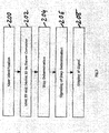
- is a flowchart of an embodiment of a method of the invention,
- Figure 3
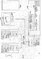
- is a block diagram of a further embodiment of an analysis system of the invention,
- Figure 4
- is a block diagram of a further embodiment of an analysis system of the invention,
- Figure 5
- is a flowchart of a further embodiment of a method of the invention,
- Figure 6
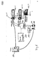
- is illustrative of an embodiment of an analysis system of the invention where the requirement for refilling a reagent is signalled to a user,
- Figure 7
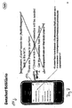
- shows an example of a screen image that is displayed on an embodiment of the mobile user device after receipt of the signal indicating the requirement for a refill,
- Figure 8
- shows the mobile user device of
fig. 7 after the user has entered a navigation command, - Figure 9
- illustrates the mobile user device of
figs. 7 and8 after the user has entered a further navigation command, the first sub-version of the specified screen image being displayed, - Figure 10
- a screen image being displayed on a monitor of one of the analyser control computers,
- Figure 11
- the mobile user device of
fig. 9 , the first sub-version having been replaced by a second sub-version, - Figure 12
- the screen image of
fig. 10 after the task has been completed, - Figure 13
- a schematic illustration of a workflow.
- In the foflowing description of the preferred embodiments like elements will be designated by identical reference numerals,
-
Figure 1 shows a block diagram of ananalysis system 100. Theanalysis system 100 comprises various analysers being coupled to analyser control computers that control operation of their respective analyser. An analyser can be coupled to an analyser control computer that controls operation of the analyser Depending on the implementation the analyser or the analyser control computer is coupled to theserver computer 108 via thenetwork 110; hence, the analyser and/or the analyser control computer can constitute a connected lab device.. In the embodiment considered here theanalysis system 100 has a connected lab device A and a connected lab device B. The connected lab device A has at least one processor 116.1 for execution of program instructions 118.1. The connected lab device A has a network interface 120.1 for coupling the connected lab device A to thenetwork 110, in particular in order to enable communication with aserver computer 108. - The
network 110 can be a cable based network, such as a local area network, an Ethernet or the like, or a wireless network, such as a WIFI, GSM, UMTS or other wireless digital network. In particular, thenetwork 110 can implement the internet protocol (IP), in particular mobile IP. For example, thenetwork 110 comprises a combination of cable-based and wireless networks. - The connected lab device A has a display, such as a computer monitor 122.1 for displaying a screen image 124.1 that may include a textual output.
- Further, the connected lab device A has a user identification component 101.1 and a device identification component 103.1.
- The user identification component 101.1 serves for identification of a
human user 104, such as a laboratory assistant. The user identification component 101.1 can be operable for the user's 104 entry of his or her user name and password. Alternatively or in addition the user identification component 101.1 can implement an RFID method for determining the user's 104 identity by means of an RFID chip card of that user. As an alternative or in addition the user identification component 101.1 can be operable to perform the user's 104 identification using a biometric method, such as fingerprint identification. In this instance the user identification component 101.1 comprises a sensor for sensing theusers 104 respective biometric features, such as a fingerprint sensor. - The device identification component 103.1 can be a protected storage area of the connected lab device A in which a unique device identifier for identification of the device is stored. This device identifier can be a serial number, such as a globally unique identifier (GUID) that is assigned to the connected lab device A during its production or it can be an identifier that is unique within the analysis system and that is assigned to the connected lab device A by an administrator of the analysis system. Alternatively the device ID is not permanently stored by the device identification component 103.1 but the device ID is computed by the device identification component 103.1 each time an identification of the connected lab device A is required. The computation of the device ID can be executed by the
device identification component 103,1 using a predefined algorithm, such as a cryptographic algorithm. - The connected lab device B of the
analysis system 100 has a design that is analogous to the connected lab device A. Thus, the connected lab device B has a user identification component 101.2, a device identification component 103.2, a processor 116.2 for execution of program instructions 118.2, a monitor 122.2 for displaying a screen image 124.2 and a metric interface 120.2 corresponding to the respective components of the connected lab device A. - The
analysis system 100 can have a plurality of additional connected lab devices not shown infigure 1 that are also coupled to theserver computer 108 over thenetwork 110. - The
server computer 108 has aprocessor 160 for execution of program instructions 162, and anetwork interface 164 for coupling theserver computer 108 to thenetwork 110. The program instructions 162 comprise aprogram module 163 for determination of a step ofworkflow 192 that is stored in astorage component 190 that is coupled to theserver computer 108, Thestorage component 190 can form an integral part of theserver computer 108 or it can be a separate component such as a database server that is either directly coupled to theserver computer 108 or via thenetwork 110. - The
workflow 192 comprises a variety of steps, such asstep 1,step 2,step 3,... In addition other workflows can be stored in thestorage 190. - In operation, the
user 104 selects one of the connected tab devices of theanalysis system 100, such as connected lab device A. By operation of the user identification component 101.1 theuser 104 is identified, such as by an entry of a user identifier. - The user's 104 identifier and the device identifier of the connected lab device A provided by the device identifier component 103.1 are sent from the interface 120.1 of the connected lab device A to the
server computer 108 via thenetwork 110. This invokes the execution of theprogram module 163 which determines a step of theworkflow 192 depending on the user identifier and the device identifier received from the connected lab device A. For example, theprogram module 163 queries a database in which theworkflow 192 is stored using the user identifier and/or the device identifier as a search term in order to retrieve a step of the workflow that is assigned to that user. - By execution of the
program module 163 theprocessor 160 generates a signal that is indicative of the determined step of the workflow. This signal is sent from theserver computer 108 via thenetwork 110 to the connected lab device identified by the device identifier, i.e. connected lab device A. In response to receipt of this signal by the connected lab device A execution of the program instructions 118.1 is invoked such that the screen image 124.1 is displayed on the monitor 122.1 including the textual output being descriptive of the determined step. As a consequence theuser 104 is informed regarding the step of theworkflow 192 to be executed by that user. -
Figure 2 shows a respective flowchart. Instep 200 the user is identified by one of the connected lab devices, such as by connected lab device A. In response to the user identification the user's identifier and the device identifier of the connected lab device that has performed the user identification, i.e. connected lab device A, are sent to the server computer instep 202. Next (step 204), the server computer performs a determination of a step of a warkflow to be executed by the user identified by the user ID received instep 202. - In
step 206 the determined step is signalled from the server computer to the connected lab device identified by the device identifier received instep 202, i,e. connected lab device A. The connected lab device displays a signal instep 208 for informing the user as to the determined step, such as by displaying a text box or a symbol and/or by another kind of visual, haptic and/or acoustic output generated by the connected lab device. -
Figure 3 shows a further embodiment of ananalysis system 100 of the invention. In the embodiment considered here thestorage component 190 is a database that stores a plurality of database tables, such as database tables 194 and 196. The database table 194 contains data for defining a number of workflows and their respecfive steps, such as a workflow I having steps I.1, I.2,... and workflow II having steps II.1, II.2,... - The database table 196 serves to assign steps of the workflows defined in the database table 194 to the various connected or unconnected lab devices of the
analysis system 100. For example, the steps I.1 to I.3 and the steps I:5 and I.6 of the walk flow I are assigned to the connected lab device A whereas the step I.4 of the workflow is assigned to the connected lab device B. This implies that the step I.4 cannot be executed using connected lab device A as it is not assigned to the connected lab device A in the database table 196 but that the connected lab device B can be used for execution of the step I.4 as this step is assigned to the connected lab device B in the database table 196. - In operation, the
server computer 108 receives the user identifier and the device identifier from one of the connected lab devices of theanalysis system 100, such as from connected lab device A, as it is the case in the embodiments offigures 1 and2 . By execution of the program module 163 a step of one of the worflow to be executed by the user identified by the user identifier is determined. For example, by execution of theProgram module 163 it is determined that the step 1.4 is to be executed by theuser 104 using the database table 194. - After determination of the step to be executed the database table 196 is accessed in order to determine if the step to be executed is assigned to the lab device identified by the device identifier received by the
server computer 108. In the example considered here, this is not the case, as the step I.4 is not assigned to the connected lab device A but to the connected lab device B in the database table 196. As a consequence execution ofprogram module 165 is invoked by theprogram module 163 such that a message is generated. - The message is indicative of the determined step of the workflow to be executed by the
user 104, i.e. step I.4, the fact that the connected lab device A cannot be used for execution of that step and/or the connected lab device B that can be used for the execution of the determined step. That message is sent from theserver computer 108 to the connected lab device A via thenetwork 110. -
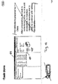
Figure 4 shows a further embodiment of theanalysis system 100 of the invention. Theanalysis system 100 of the embodiment offigure 4 has one or more mobile devices, such asmobile device 106. Themobile device 106 has an integrateddisplay 130 for displaying ascreen image 132 that may contain a textual or other visual output. Further, themobile device 106 has anetwork interface 198 for coupling to thenetwork 110. - The
analysis system 100 has one or more unconnected lab devices, such as unconnectedlab device C 180, For example, the unconnected lab device C is a refrigerator for storing reagents that are required for operating the various analyzers of theanalysis system 100. - A step I.7 is assigned to the unconnected lab device C in the database table 196.
- In operation, the user selects one of the connected lab devices A or B as in the embodiments of
figures 1 to 3 , such that theserver computer 108 receives a user identifier and a device identifier. Alternatively the user may select themobile device 106 such that a user identifier and a mobile device identifier are received by theserver computer 108 instead. The user identifier and the device identifier are used by theprogram module 163 for determination of the step of the workflow to be executed by theuser 104 by means of the database table 194 as is the case in the embodiments offigures 1 to 3 . - For convenience of explanation and without restriction of generality it is assumed here that the determined step is step I.7. As this step is not assigned to one of the connected lab devices or the
mobile device 106 the devise identifier received by theserver computer 108 is not matching the lab device to which the step I.7 is assigned in the database table 196 such that theprogram module 163 invokes execution of theprogram module 165. Theprogram module 165 sends its message to themobile device 106 indicating the determined step to be executed by theuser 104 and the unconnected tab device C at which this determined step is to be executed. In addition the message may also indicate a location of the unconnected lab device C, such as a laboratory room number in which the unconnected lab device C is located. This position information may also be stored in the database table 196. - Upon receipt of this message on the
mobile device 106 theuser 104 can walk to the unconnected lab device C for execution of the determined step. After completion of the execution of the determined step theuser 104 may use themobile device 106 in order to acknowledge completion of the execution which is signalled from themobile device 106 back to theserver computer 108 in order to mark the respective step I.7 as completed in the database table 194. -
Figure 5 shows a respective flowchart. Instep 300 the user selects one of the connected lab devices, such as lab device A. The user is identified by the selected lab device A and the user identifier and device identifier of the lab device A are transmitted to the server computer in step 302. In step 304 a step of the workflow to be executed by the user identified by the user identifier is determined by the server computer. If this step is to be executed at an unconnected lab device, such as lab device C, the determined step is signalled from the server computer to the mobile device instep 306. This may include a description of the step to be executed and/or the location of the lab device C. - In
step 308 the user executes the determined step at the unconnected lab device and signals completion of the execution of this step from the mobile device to the server computer in step 310 such as by entering an acknowledgement regarding completion of the step into the mobile device. -
Fig. 6 shows an exemplary embodiment of an analysis system of the invention comprising an analyser 102.1 of thecabas 6000 type having the device identifier 'Cane', analyser 102.2 of thecobas 6000 type having the device ID 'Cavallo' and analyser 102.3 of theintegra 800 type having the device ID 'Calamaro', The analyser 102.1 and its analyser control computer 104.1 constitute connected lab device A and the analyser 102.2 and its analyser control computer 104.2 constitute connected lab device B (cf.Fig. 1 to 5 ). The analysis system further comprises theunconnected lab device 180 which is a refrigerator for storing a stock of reagents. - In operation, one of the analyzers, such as the analyser 102.1, requires refilling of a reagent. For example, this is sensed by means of a sensor that is coupled to the analyser control computer 104.1. When the charging level of the reagent of the analyser 102.1 is below a predefined threshold level, the analyser control computer 104.1 generates a
signal 182 that is sent to themobile device 106 either directly or through the intermediary of theserver computer 108. In one embodiment the analyser control computer 104.1 sends thesignal 182 to theserver computer 108 which then selects themobile user device 106 for forwarding thesignal 182. -
Fig. 7 shows an embodiment ofmobile device 106. Thecurrent screen image 132 that is displayed on thedisplay 130 of themobile user device 106 shows a number of due and announced tasks to be executed by the user. - The creation of a task may occur in the following instance:
- When one of the analyzers is powered up it may execute a self-diagnosis. As a result of the self-diagnosis the analyzer or the analyzer control computer coupled to it may determine that the execution of one or more tasks is required. It may e.g. be detected by performing the self-diagnoses or by an error message that it is required to refill a reagent, or that a calibration is due.
- The user himself or herself recognizes that the execution of a certain task is required and thus selects the respective task to become a due or a current task.
- During the ongoing operation of the analysis system the execution of one or more tasks may become necessary which may be determined automatical by the analysis system or by the user.
- There can be various ways to assign tasks to users depending on the implementation:
- When an analyzer requires the execution of a certain task, such as as a result of its self-diagnosis, the user that attempts to utilize that analyzer is automatically assigned this task.
- When the execution of a task becomes necessary as determined automatically by the analysis system or one of the users, this requirement is transmitted to all users or at least a group of the users as a broadcast or a multicast message, such that one of the users can select that task to become his or her due or current task.
- Certain tasks can be pro-assigned to a specific user or user group.
- The assignment of tasks to users can be implemented by means of the workflow management system.
- In the embodiment considered here, the current task that is currently selected by the user is marked by (*). Hence 'Prepare: Cavallo' is the current task.
- Due to the signal 182 (cf.
fig. 6 ) an additional due task appears on the display 932 which is 'Refill Reagents: Cane'. The user can interrupt the execution of the current task 'Prepare: Cavallo' for selection of 'Refill Reagents: Cane' to become the current task or the user may complete the current task before selecting the next task to become the current task which is within the user's discretion. After the user's selection of 'Refill Reagents: Cane' to become the current task thedisplay screen 132 offig. 8 is shown. - When the user selects 'Refill Reagents; Cane' to become the current task, the
server computer 108 reads analyser status information for at least Cane or all other available analyzers from the database 166 and provides the retrieved analyse status information to themobile user device 106 where thescreen image 132 is generated and displayed. In the embodiment depicted infig. 8 thescreen image 132 provides an overview to the user regarding the filing levels of the various analyzers of the analysis system. - By selection of the
navigation button 184 the user can navigate from the currently selected tree node, to another tree node of the user interface; the selection of thenavigation button 184 is signalled from themobile user device 106 to theserver computer 108. In response therespective screen image 132 is displayed as shown infig. 9 . - In the example considered here the
screen image 132 shows detailed information regarding the filling level of 'Cane'. Theimage screen 132 comprisescontrol buttons - When the user decides to execute the current task directly from the
analyser control computer 104 thescreen image 124 is displayed on the monitor 122 in the interactive mode, thus containing thecontrol buttons screen image 132. - For changing to the
analyser control computer 104 the user may perform a log-in operation or, if the user is already logged-in, an unspecific entry operation, such as a mouse click. In response themobile user device 106 is put into the display mode by theserver computer 108. As a result thecontrol buttons screen image 132 of themobile user device 106 as shown infig. 11 . -
Fig. 12 shows thescreen image 124 after completion of the execution of the current task, i.e. after the refill of the reagent of Cane has been executed. It is important to note that the context of the current user navigation is preserved despite the completion of the current task. -
Fig. 13 illustrates the execution of a task that comprisessteps 1 to 6. One of the steps, i.e. step 4, can only be performed from a specific device, such as from the analyser control computer, but not from the mobile user device, whereas all other steps can be performed both from the mobile user device and from the analyzer control computer. For example, execution of the task is started from the mobile user device. When the task execution reaches completion ofstep 3, the mobile user device is put into the display mode and the user changes to the analyser control computer in order to use the analyser control computer to perform the following steps 4 to 6. -
100 Analysis system 101 User identification component 102 Analyser 103 Device identification component 104 User 106 Mobile user device 108 Server computer 110 Network 116 Processor 118 Program instructions 120 Network interface 122 Monitor 124 Screen image 130 Display 132 Screen image 160 Processor 162 Program instructions 163 Program module 164 Network interface 165 Program module 166 Database 168 Log-in signal 170 Session 172 Session 174 Database table 176 Storage 180 Unconnected lab device 182 Signal 184 Navigation button 186 Control button 188 Control button 190 Storage component 192 Workflow 194 Database table 196 Database table 198 Network interface
Claims (15)
- An analysis system for analyzing biological samples comprising:- at least first and second lab devices, at least one of the lab devices having a user identification component (101.1, 101.2) for identifying a user (104), a device identification component (103.1, 103.2) for identifying the lab devices, and an interface component for sending a user identifier of the identified user and a device identifier of the lab device,- a server computer (108) haying a server interface component (164) for receiving the user identifier and the device identifier, a processing component (160) for determining a step of a workflow (192) to be executed by the identified user, wherein the server interface component is operable to send a signal being indicative of the determined steps of the workflow to the lab device identified by the device identifier.
- The analysis system of claim 1, the interface component of the lab device being operable for signaling completion of the execution of the determined step to the server computer.
- The analysis system of claim 1 or 2, the server computer further comprising a database (190) for assigning a first set of the steps of the workflow to the first lab device and for assigning a second set of the steps of the workflow to the second lab device.
- The analysis system of claim 3, the processing component being adapted for generating a message when the determined step is not assigned to the identified lab device in the database, the server interface component being operable for sending the message to the identified lab device.
- The analysis system of claim 4, the message being indicative of at least one of the lab devices to which the determined step is assigned.
- The analysis system of anyone of the preceding claims, the analysis system further comprise at least one mobile device (106), wherein the mobile device is adapted to receive the signal being indicative of the determined step of the workflow and the signal being indicative of one of the lab devices to be used for execution of the determined step of then workflow.
- A method being implemented by an analysis system for analyzing biological sample, the method comprising the steps of:- identifying a user (104) by one of first and second lab devices,- sending of a user identifier of the identified user and a device identifier of the one of the first and second lab devices to a server computer (108),- determining a step of a workflow by the server computer using the user identifier and the device identifier,- sending a signal being indicative of the determined step from the server computer to the one of the lab devices.
- The method of claim 7, further comprising:- identifying the user using another one of the first and second lab devices,- sending a user identifier identifying the user and a device identifier of the other one of the first and second lab devices from the other one of the lab devices to the server computer,- determining a step of the workflow to be executed by the identified user,- sending a signal being indicative of the determined step of the workflow to the other lab device.
- The method of claim 7 or 8, the analysis system further comprising at least one mobile device (106), wherein the mobile device receives the signal being indicative of the at least one determined step of the workflow and the signal being indicative of one of the lab devices to be used for execution of the at least one step of the workflow.
- The method of claim 9, the signal being indicative of position information indicating a geographic or typological location of the lab device to be used for the execution of the at least one step.
- The method of claim 9 or 10, the analysis system further comprising an unconnected lab device (180) that is not coupled to the server computer, wherein the signal is indicative of one or more steps of the workflow to be executed at the unconnected lab device.
- The method of any one of the preceding claims 9 to 11, the signal being indicative of a priority of the steps of the workflow, and wherein the mobile device or the lab device displays the steps in a prioritized order.
- The method of any one of claims 9 to 12, further comprising signaling completion of the step of the workflow from the mobile device to the server computer.
- The method of claim 13, further comprising executing the step of the workflow at an unconnected lab device.
- A computer program product comprising executable instructions for performing a method of any one of the preceding claims 7 to 14.
Priority Applications (7)
| Application Number | Priority Date | Filing Date | Title |
|---|---|---|---|
| ES09170598.8T ES2554993T3 (en) | 2009-09-17 | 2009-09-17 | Analysis system for the analysis of biological samples, methods and software product |
| EP09170598.8A EP2299277B1 (en) | 2009-09-17 | 2009-09-17 | Analysis system for analysing biological samples, methods and computer program product |
| JP2010203897A JP5319631B2 (en) | 2009-09-17 | 2010-09-13 | Biological sample analysis system, method and computer program product |
| US12/883,271 US8511549B2 (en) | 2009-09-17 | 2010-09-16 | Analysis system for analyzing biological samples, methods, and computer program product thereof |
| CN201010286076.7A CN102024098B (en) | 2009-09-17 | 2010-09-16 | For analytical system and the method for analyzing biological samples |
| US13/928,821 US8651377B2 (en) | 2009-09-17 | 2013-06-27 | Analysis system for analyzing biological samples, methods, and computer program product thereof |
| US14/149,878 US8985441B2 (en) | 2009-09-17 | 2014-01-08 | Analysis system for analyzing biological samples, methods, and computer program product thereof |
Applications Claiming Priority (1)
| Application Number | Priority Date | Filing Date | Title |
|---|---|---|---|
| EP09170598.8A EP2299277B1 (en) | 2009-09-17 | 2009-09-17 | Analysis system for analysing biological samples, methods and computer program product |
Publications (2)
| Publication Number | Publication Date |
|---|---|
| EP2299277A1 true EP2299277A1 (en) | 2011-03-23 |
| EP2299277B1 EP2299277B1 (en) | 2015-10-21 |
Family
ID=41680930
Family Applications (1)
| Application Number | Title | Priority Date | Filing Date |
|---|---|---|---|
| EP09170598.8A Active EP2299277B1 (en) | 2009-09-17 | 2009-09-17 | Analysis system for analysing biological samples, methods and computer program product |
Country Status (5)
| Country | Link |
|---|---|
| US (3) | US8511549B2 (en) |
| EP (1) | EP2299277B1 (en) |
| JP (1) | JP5319631B2 (en) |
| CN (1) | CN102024098B (en) |
| ES (1) | ES2554993T3 (en) |
Cited By (5)
| Publication number | Priority date | Publication date | Assignee | Title |
|---|---|---|---|---|
| EP2857841A1 (en) * | 2013-10-07 | 2015-04-08 | Eppendorf Ag | Configuration control for a laboratory device, a laboratory device with the configuration control for the device-controlled treatment of at least one laboratory sample, and a method for the configuration of the laboratory device by means of the configuration control |
| US10439824B2 (en) | 2016-09-01 | 2019-10-08 | Roche Diagnostics Operations, Inc. | Method for authenticating an instrument for processing a biological sample or reagent and system comprising an instrument for processing a biological sample or reagent |
| US10466262B2 (en) | 2013-10-07 | 2019-11-05 | Eppendorf Ag | Laboratory instrument with access control device and method for instrument-controlled treatment of laboratory samples |
| US10551397B2 (en) | 2013-10-07 | 2020-02-04 | Eppendorf Ag | System comprising at least two laboratory instruments for instrument-controlled handling of a partial problem in a treatment process containing treatments of at least one laboratory sample, laboratory instrument and method |
| US10739362B2 (en) | 2013-10-07 | 2020-08-11 | Eppendorf Ag | Laboratory instrument, system and method for instrument-controlled treatment of at least one laboratory sample using at least one consumable |
Families Citing this family (13)
| Publication number | Priority date | Publication date | Assignee | Title |
|---|---|---|---|---|
| JP5727219B2 (en) * | 2010-12-28 | 2015-06-03 | シスメックス株式会社 | Sample analyzer and sample analysis system |
| CN107377025B (en) * | 2011-09-30 | 2020-11-10 | 生命技术公司 | System and method for biological analysis |
| EP2787352A1 (en) * | 2013-04-05 | 2014-10-08 | F. Hoffmann-La Roche AG | Analysis system for a biological sample |
| US10447573B2 (en) * | 2014-07-17 | 2019-10-15 | Sysmex Corporation | Method and system for aggregating diagnostic analyzer related information |
| EP3091458B1 (en) | 2015-05-02 | 2021-02-24 | F. Hoffmann-La Roche AG | Point-of-care testing system |
| EP3091457B1 (en) | 2015-05-02 | 2018-10-24 | F. Hoffmann-La Roche AG | Point-of-care testing system |
| US10091279B2 (en) | 2015-05-27 | 2018-10-02 | FlowJo, LLC | Wireless connected laboratory |
| WO2020016123A1 (en) * | 2018-07-20 | 2020-01-23 | Bayer Business Services Gmbh | Laboratory management system |
| US20220285014A1 (en) * | 2019-08-07 | 2022-09-08 | Hitachi High-Tech Corporation | Automatic analysis system and alarm handling method |
| EP4066097A1 (en) | 2019-11-27 | 2022-10-05 | Corning Incorporated | Connected ecosystem for laboratory environment |
| WO2021108113A1 (en) | 2019-11-27 | 2021-06-03 | Corning Incorporated | Sensing vessels for cell cultures |
| US20210286604A1 (en) * | 2020-03-16 | 2021-09-16 | GenoFab, Inc. | Methods, services, systems, and architectures to optimize laboratory processes |
| EP4243028A1 (en) | 2022-03-10 | 2023-09-13 | F. Hoffmann-La Roche AG | Intelligent user guidance for laboratory issue resolution |
Citations (6)
| Publication number | Priority date | Publication date | Assignee | Title |
|---|---|---|---|---|
| WO2004102163A2 (en) | 2003-03-17 | 2004-11-25 | Joule Microsystems Canada Inc. | System enabling remote analysis of fluids |
| EP1691186A1 (en) | 2005-02-11 | 2006-08-16 | Sakura Finetek U.S.A., Inc. | Automated reagent dispensing system and method of operation |
| EP1840576A2 (en) | 2006-03-30 | 2007-10-03 | Sysmex Corporation | Automatic analyzer and information providing system therefor |
| US20080168850A1 (en) | 2007-01-12 | 2008-07-17 | Fischer Gregory T | Display For Simultaneously Monitored Analytical Devices |
| EP1959257A2 (en) | 2007-02-19 | 2008-08-20 | Hitachi High-Technologies Corporation | Automatic analyzer |
| WO2009085534A1 (en) | 2007-12-27 | 2009-07-09 | Siemens Heathcare Diagnostics Inc. | Method and apparatus for remote multiple-process graphical monitoring |
Family Cites Families (17)
| Publication number | Priority date | Publication date | Assignee | Title |
|---|---|---|---|---|
| JP3760806B2 (en) * | 2001-06-25 | 2006-03-29 | 株式会社日立製作所 | Analysis result management method and apparatus |
| AU2002365257A1 (en) * | 2001-10-26 | 2003-07-24 | Zeosoft Corporation | Development, management of distributed clients and servers |
| JP2003329690A (en) * | 2002-05-09 | 2003-11-19 | Sysmex Corp | Clinical examination system |
| AU2003247009A1 (en) * | 2002-07-31 | 2004-02-23 | Truecontext Corporation | Contextual computing system |
| NO20033115D0 (en) | 2003-07-08 | 2003-07-08 | Amersham Health As | Peptide-based compounds |
| JP2005106669A (en) * | 2003-09-30 | 2005-04-21 | Olympus Corp | Reaction/measurement system of organism-related substance |
| US20060089855A1 (en) * | 2003-10-07 | 2006-04-27 | Holland Geoffrey N | Medication management system |
| US7443303B2 (en) | 2005-01-10 | 2008-10-28 | Hill-Rom Services, Inc. | System and method for managing workflow |
| US20070168562A1 (en) | 2005-12-14 | 2007-07-19 | Kimbrell Jacob W | Participant-selective event synchronization for portable electronic devices |
| JP2009047592A (en) * | 2007-08-21 | 2009-03-05 | Shimadzu Corp | Analysis equipment |
| US20090094529A1 (en) | 2007-10-09 | 2009-04-09 | General Electric Company | Methods and systems for context sensitive workflow management in clinical information systems |
| JP2009162584A (en) * | 2007-12-28 | 2009-07-23 | Olympus Corp | Management system |
| US20090259493A1 (en) * | 2008-04-11 | 2009-10-15 | Venon Medhi O | Mobile health book |
| US10679308B2 (en) * | 2008-06-03 | 2020-06-09 | Xerox Corporation | Device and method for delivering medical lab reports |
| US20090307137A1 (en) * | 2008-06-09 | 2009-12-10 | Microsoft Corporation | Managing provenance of digitally signed data in user editable records |
| WO2010006303A2 (en) * | 2008-07-10 | 2010-01-14 | Nodality, Inc. | Methods and apparatus related to management of experiments |
| US20140012677A1 (en) * | 2011-12-21 | 2014-01-09 | Paul F. Wagner | Mobile Device Application for Dynamic Delivery of Advertising-Based Content |
-
2009
- 2009-09-17 EP EP09170598.8A patent/EP2299277B1/en active Active
- 2009-09-17 ES ES09170598.8T patent/ES2554993T3/en active Active
-
2010
- 2010-09-13 JP JP2010203897A patent/JP5319631B2/en not_active Expired - Fee Related
- 2010-09-16 CN CN201010286076.7A patent/CN102024098B/en not_active Expired - Fee Related
- 2010-09-16 US US12/883,271 patent/US8511549B2/en active Active
-
2013
- 2013-06-27 US US13/928,821 patent/US8651377B2/en active Active
-
2014
- 2014-01-08 US US14/149,878 patent/US8985441B2/en active Active
Patent Citations (6)
| Publication number | Priority date | Publication date | Assignee | Title |
|---|---|---|---|---|
| WO2004102163A2 (en) | 2003-03-17 | 2004-11-25 | Joule Microsystems Canada Inc. | System enabling remote analysis of fluids |
| EP1691186A1 (en) | 2005-02-11 | 2006-08-16 | Sakura Finetek U.S.A., Inc. | Automated reagent dispensing system and method of operation |
| EP1840576A2 (en) | 2006-03-30 | 2007-10-03 | Sysmex Corporation | Automatic analyzer and information providing system therefor |
| US20080168850A1 (en) | 2007-01-12 | 2008-07-17 | Fischer Gregory T | Display For Simultaneously Monitored Analytical Devices |
| EP1959257A2 (en) | 2007-02-19 | 2008-08-20 | Hitachi High-Technologies Corporation | Automatic analyzer |
| WO2009085534A1 (en) | 2007-12-27 | 2009-07-09 | Siemens Heathcare Diagnostics Inc. | Method and apparatus for remote multiple-process graphical monitoring |
Non-Patent Citations (2)
| Title |
|---|
| TIMM U ET AL: "Concept and specification of LIMS for pharmacokinetic studies", LABORATORY AUTOMATION & INFORMATION MANAGEMENT, ELSEVIER SCIENCE PUBLISHERS BV., AMSTERDAM, NL, vol. 32, no. 1, 1 May 1996 (1996-05-01), pages 7 - 22, XP004052646, ISSN: 1381-141X * |
| U. TIMM; K. FUCHS: "Concept and specification of LIMS for pharmacokinetic studies", LABORATORY AUTOMATION AND INFORMATION MANAGEMENT, vol. 32, 1996, pages 7 - 22 |
Cited By (8)
| Publication number | Priority date | Publication date | Assignee | Title |
|---|---|---|---|---|
| EP2857841A1 (en) * | 2013-10-07 | 2015-04-08 | Eppendorf Ag | Configuration control for a laboratory device, a laboratory device with the configuration control for the device-controlled treatment of at least one laboratory sample, and a method for the configuration of the laboratory device by means of the configuration control |
| US10452035B2 (en) | 2013-10-07 | 2019-10-22 | Eppendorf Ag | Laboratory instrument for instrument-controlled treatment of at least one laboratory sample |
| US10466262B2 (en) | 2013-10-07 | 2019-11-05 | Eppendorf Ag | Laboratory instrument with access control device and method for instrument-controlled treatment of laboratory samples |
| US10551397B2 (en) | 2013-10-07 | 2020-02-04 | Eppendorf Ag | System comprising at least two laboratory instruments for instrument-controlled handling of a partial problem in a treatment process containing treatments of at least one laboratory sample, laboratory instrument and method |
| US10739362B2 (en) | 2013-10-07 | 2020-08-11 | Eppendorf Ag | Laboratory instrument, system and method for instrument-controlled treatment of at least one laboratory sample using at least one consumable |
| US11536738B2 (en) | 2013-10-07 | 2022-12-27 | Eppendorf Se | System comprising at least two laboratory instruments for instrument-controlled handling of a partial problem in a treatment process containing treatments of at least one laboratory sample, laboratory instrument and method |
| US12385932B2 (en) | 2013-10-07 | 2025-08-12 | Eppendorf Se | Laboratory instrument, system and method for instrument-controlled treatment of at least one laboratory sample using at least one consumable |
| US10439824B2 (en) | 2016-09-01 | 2019-10-08 | Roche Diagnostics Operations, Inc. | Method for authenticating an instrument for processing a biological sample or reagent and system comprising an instrument for processing a biological sample or reagent |
Also Published As
| Publication number | Publication date |
|---|---|
| US8511549B2 (en) | 2013-08-20 |
| CN102024098B (en) | 2016-05-18 |
| CN102024098A (en) | 2011-04-20 |
| ES2554993T3 (en) | 2015-12-28 |
| EP2299277B1 (en) | 2015-10-21 |
| US20130289888A1 (en) | 2013-10-31 |
| JP5319631B2 (en) | 2013-10-16 |
| US20110220715A1 (en) | 2011-09-15 |
| JP2011064682A (en) | 2011-03-31 |
| US8985441B2 (en) | 2015-03-24 |
| US20140117089A1 (en) | 2014-05-01 |
| US8651377B2 (en) | 2014-02-18 |
Similar Documents
| Publication | Publication Date | Title |
|---|---|---|
| EP2299277B1 (en) | Analysis system for analysing biological samples, methods and computer program product | |
| EP2416267A1 (en) | Method of aggregating task data objects and for providing an aggregated view | |
| US20170142324A1 (en) | Method for generating an entry for an electronic laboratory journal | |
| US10248373B2 (en) | Analysis system for analyzing biological samples, data processing method and computer program product | |
| EP2352033A2 (en) | Sample analyzer, sample analyzing method and computer program product | |
| CN105277677B (en) | Method and system for aggregating information related to a diagnostic analyzer | |
| US20110208536A1 (en) | Clinical test information managing apparatus and non-transitory storage medium | |
| US20240305571A1 (en) | Filtering data from an analytical device | |
| CN109387648A (en) | Automatic analysis system | |
| JP2011198103A (en) | Operation support program, operation support method, and operation support device | |
| CN113724813A (en) | Data transmission method, device, equipment and storage medium based on LIS system | |
| JP2009289113A (en) | Apparatus, program and method for collecting information | |
| US8869266B2 (en) | Management system of test device and management method thereof | |
| CN106055913A (en) | Information processing method and smart medical system | |
| CN115732048A (en) | Analysis system, management server, analysis device, and method | |
| EP4513192A1 (en) | Automatic analysis system and mobile terminal | |
| US20250147057A1 (en) | Remote analyzer monitoring | |
| CN114267427B (en) | Sample scheduling method, device, sample management terminal and storage medium | |
| US20220276275A1 (en) | Troubleshooting by proximity interaction and voice command |
Legal Events
| Date | Code | Title | Description |
|---|---|---|---|
| PUAI | Public reference made under article 153(3) epc to a published international application that has entered the european phase |
Free format text: ORIGINAL CODE: 0009012 |
|
| AK | Designated contracting states |
Kind code of ref document: A1 Designated state(s): AT BE BG CH CY CZ DE DK EE ES FI FR GB GR HR HU IE IS IT LI LT LU LV MC MK MT NL NO PL PT RO SE SI SK SM TR |
|
| AX | Request for extension of the european patent |
Extension state: AL BA RS |
|
| 17P | Request for examination filed |
Effective date: 20110923 |
|
| RIC1 | Information provided on ipc code assigned before grant |
Ipc: G01N 35/00 20060101AFI20120508BHEP |
|
| 17Q | First examination report despatched |
Effective date: 20121023 |
|
| REG | Reference to a national code |
Ref country code: DE Ref legal event code: R079 Ref document number: 602009034317 Country of ref document: DE Free format text: PREVIOUS MAIN CLASS: G01N0035000000 Ipc: G06F0019100000 |
|
| RIC1 | Information provided on ipc code assigned before grant |
Ipc: G01N 35/00 20060101ALI20150226BHEP Ipc: G06F 19/10 20110101AFI20150226BHEP |
|
| GRAP | Despatch of communication of intention to grant a patent |
Free format text: ORIGINAL CODE: EPIDOSNIGR1 |
|
| INTG | Intention to grant announced |
Effective date: 20150423 |
|
| GRAS | Grant fee paid |
Free format text: ORIGINAL CODE: EPIDOSNIGR3 |
|
| GRAA | (expected) grant |
Free format text: ORIGINAL CODE: 0009210 |
|
| AK | Designated contracting states |
Kind code of ref document: B1 Designated state(s): AT BE BG CH CY CZ DE DK EE ES FI FR GB GR HR HU IE IS IT LI LT LU LV MC MK MT NL NO PL PT RO SE SI SK SM TR |
|
| REG | Reference to a national code |
Ref country code: GB Ref legal event code: FG4D Ref country code: NL Ref legal event code: MP Effective date: 20151021 |
|
| REG | Reference to a national code |
Ref country code: CH Ref legal event code: EP |
|
| REG | Reference to a national code |
Ref country code: AT Ref legal event code: REF Ref document number: 757014 Country of ref document: AT Kind code of ref document: T Effective date: 20151115 |
|
| REG | Reference to a national code |
Ref country code: IE Ref legal event code: FG4D |
|
| REG | Reference to a national code |
Ref country code: DE Ref legal event code: R096 Ref document number: 602009034317 Country of ref document: DE |
|
| REG | Reference to a national code |
Ref country code: ES Ref legal event code: FG2A Ref document number: 2554993 Country of ref document: ES Kind code of ref document: T3 Effective date: 20151228 |
|
| REG | Reference to a national code |
Ref country code: LT Ref legal event code: MG4D |
|
| REG | Reference to a national code |
Ref country code: AT Ref legal event code: MK05 Ref document number: 757014 Country of ref document: AT Kind code of ref document: T Effective date: 20151021 |
|
| PG25 | Lapsed in a contracting state [announced via postgrant information from national office to epo] |
Ref country code: NO Free format text: LAPSE BECAUSE OF FAILURE TO SUBMIT A TRANSLATION OF THE DESCRIPTION OR TO PAY THE FEE WITHIN THE PRESCRIBED TIME-LIMIT Effective date: 20160121 Ref country code: HR Free format text: LAPSE BECAUSE OF FAILURE TO SUBMIT A TRANSLATION OF THE DESCRIPTION OR TO PAY THE FEE WITHIN THE PRESCRIBED TIME-LIMIT Effective date: 20151021 Ref country code: IS Free format text: LAPSE BECAUSE OF FAILURE TO SUBMIT A TRANSLATION OF THE DESCRIPTION OR TO PAY THE FEE WITHIN THE PRESCRIBED TIME-LIMIT Effective date: 20160221 Ref country code: NL Free format text: LAPSE BECAUSE OF FAILURE TO SUBMIT A TRANSLATION OF THE DESCRIPTION OR TO PAY THE FEE WITHIN THE PRESCRIBED TIME-LIMIT Effective date: 20151021 Ref country code: LT Free format text: LAPSE BECAUSE OF FAILURE TO SUBMIT A TRANSLATION OF THE DESCRIPTION OR TO PAY THE FEE WITHIN THE PRESCRIBED TIME-LIMIT Effective date: 20151021 |
|
| PG25 | Lapsed in a contracting state [announced via postgrant information from national office to epo] |
Ref country code: GR Free format text: LAPSE BECAUSE OF FAILURE TO SUBMIT A TRANSLATION OF THE DESCRIPTION OR TO PAY THE FEE WITHIN THE PRESCRIBED TIME-LIMIT Effective date: 20160122 Ref country code: SE Free format text: LAPSE BECAUSE OF FAILURE TO SUBMIT A TRANSLATION OF THE DESCRIPTION OR TO PAY THE FEE WITHIN THE PRESCRIBED TIME-LIMIT Effective date: 20151021 Ref country code: PL Free format text: LAPSE BECAUSE OF FAILURE TO SUBMIT A TRANSLATION OF THE DESCRIPTION OR TO PAY THE FEE WITHIN THE PRESCRIBED TIME-LIMIT Effective date: 20151021 Ref country code: FI Free format text: LAPSE BECAUSE OF FAILURE TO SUBMIT A TRANSLATION OF THE DESCRIPTION OR TO PAY THE FEE WITHIN THE PRESCRIBED TIME-LIMIT Effective date: 20151021 Ref country code: LV Free format text: LAPSE BECAUSE OF FAILURE TO SUBMIT A TRANSLATION OF THE DESCRIPTION OR TO PAY THE FEE WITHIN THE PRESCRIBED TIME-LIMIT Effective date: 20151021 Ref country code: AT Free format text: LAPSE BECAUSE OF FAILURE TO SUBMIT A TRANSLATION OF THE DESCRIPTION OR TO PAY THE FEE WITHIN THE PRESCRIBED TIME-LIMIT Effective date: 20151021 Ref country code: PT Free format text: LAPSE BECAUSE OF FAILURE TO SUBMIT A TRANSLATION OF THE DESCRIPTION OR TO PAY THE FEE WITHIN THE PRESCRIBED TIME-LIMIT Effective date: 20160222 |
|
| REG | Reference to a national code |
Ref country code: DE Ref legal event code: R097 Ref document number: 602009034317 Country of ref document: DE |
|
| PG25 | Lapsed in a contracting state [announced via postgrant information from national office to epo] |
Ref country code: CZ Free format text: LAPSE BECAUSE OF FAILURE TO SUBMIT A TRANSLATION OF THE DESCRIPTION OR TO PAY THE FEE WITHIN THE PRESCRIBED TIME-LIMIT Effective date: 20151021 |
|
| REG | Reference to a national code |
Ref country code: FR Ref legal event code: PLFP Year of fee payment: 8 |
|
| PLBE | No opposition filed within time limit |
Free format text: ORIGINAL CODE: 0009261 |
|
| STAA | Information on the status of an ep patent application or granted ep patent |
Free format text: STATUS: NO OPPOSITION FILED WITHIN TIME LIMIT |
|
| PG25 | Lapsed in a contracting state [announced via postgrant information from national office to epo] |
Ref country code: DK Free format text: LAPSE BECAUSE OF FAILURE TO SUBMIT A TRANSLATION OF THE DESCRIPTION OR TO PAY THE FEE WITHIN THE PRESCRIBED TIME-LIMIT Effective date: 20151021 Ref country code: SK Free format text: LAPSE BECAUSE OF FAILURE TO SUBMIT A TRANSLATION OF THE DESCRIPTION OR TO PAY THE FEE WITHIN THE PRESCRIBED TIME-LIMIT Effective date: 20151021 Ref country code: RO Free format text: LAPSE BECAUSE OF FAILURE TO SUBMIT A TRANSLATION OF THE DESCRIPTION OR TO PAY THE FEE WITHIN THE PRESCRIBED TIME-LIMIT Effective date: 20151021 Ref country code: EE Free format text: LAPSE BECAUSE OF FAILURE TO SUBMIT A TRANSLATION OF THE DESCRIPTION OR TO PAY THE FEE WITHIN THE PRESCRIBED TIME-LIMIT Effective date: 20151021 Ref country code: SM Free format text: LAPSE BECAUSE OF FAILURE TO SUBMIT A TRANSLATION OF THE DESCRIPTION OR TO PAY THE FEE WITHIN THE PRESCRIBED TIME-LIMIT Effective date: 20151021 |
|
| 26N | No opposition filed |
Effective date: 20160722 |
|
| PG25 | Lapsed in a contracting state [announced via postgrant information from national office to epo] |
Ref country code: SI Free format text: LAPSE BECAUSE OF FAILURE TO SUBMIT A TRANSLATION OF THE DESCRIPTION OR TO PAY THE FEE WITHIN THE PRESCRIBED TIME-LIMIT Effective date: 20151021 |
|
| PG25 | Lapsed in a contracting state [announced via postgrant information from national office to epo] |
Ref country code: BE Free format text: LAPSE BECAUSE OF FAILURE TO SUBMIT A TRANSLATION OF THE DESCRIPTION OR TO PAY THE FEE WITHIN THE PRESCRIBED TIME-LIMIT Effective date: 20151021 |
|
| PG25 | Lapsed in a contracting state [announced via postgrant information from national office to epo] |
Ref country code: MC Free format text: LAPSE BECAUSE OF FAILURE TO SUBMIT A TRANSLATION OF THE DESCRIPTION OR TO PAY THE FEE WITHIN THE PRESCRIBED TIME-LIMIT Effective date: 20151021 |
|
| REG | Reference to a national code |
Ref country code: IE Ref legal event code: MM4A |
|
| PG25 | Lapsed in a contracting state [announced via postgrant information from national office to epo] |
Ref country code: IE Free format text: LAPSE BECAUSE OF NON-PAYMENT OF DUE FEES Effective date: 20160917 |
|
| REG | Reference to a national code |
Ref country code: FR Ref legal event code: PLFP Year of fee payment: 9 |
|
| PG25 | Lapsed in a contracting state [announced via postgrant information from national office to epo] |
Ref country code: LU Free format text: LAPSE BECAUSE OF NON-PAYMENT OF DUE FEES Effective date: 20160917 |
|
| PG25 | Lapsed in a contracting state [announced via postgrant information from national office to epo] |
Ref country code: CY Free format text: LAPSE BECAUSE OF FAILURE TO SUBMIT A TRANSLATION OF THE DESCRIPTION OR TO PAY THE FEE WITHIN THE PRESCRIBED TIME-LIMIT Effective date: 20151021 Ref country code: HU Free format text: LAPSE BECAUSE OF FAILURE TO SUBMIT A TRANSLATION OF THE DESCRIPTION OR TO PAY THE FEE WITHIN THE PRESCRIBED TIME-LIMIT; INVALID AB INITIO Effective date: 20090917 |
|
| PG25 | Lapsed in a contracting state [announced via postgrant information from national office to epo] |
Ref country code: MK Free format text: LAPSE BECAUSE OF FAILURE TO SUBMIT A TRANSLATION OF THE DESCRIPTION OR TO PAY THE FEE WITHIN THE PRESCRIBED TIME-LIMIT Effective date: 20151021 Ref country code: TR Free format text: LAPSE BECAUSE OF FAILURE TO SUBMIT A TRANSLATION OF THE DESCRIPTION OR TO PAY THE FEE WITHIN THE PRESCRIBED TIME-LIMIT Effective date: 20151021 Ref country code: MT Free format text: LAPSE BECAUSE OF NON-PAYMENT OF DUE FEES Effective date: 20160930 |
|
| PG25 | Lapsed in a contracting state [announced via postgrant information from national office to epo] |
Ref country code: BG Free format text: LAPSE BECAUSE OF FAILURE TO SUBMIT A TRANSLATION OF THE DESCRIPTION OR TO PAY THE FEE WITHIN THE PRESCRIBED TIME-LIMIT Effective date: 20151021 |
|
| REG | Reference to a national code |
Ref country code: FR Ref legal event code: PLFP Year of fee payment: 10 |
|
| REG | Reference to a national code |
Ref country code: DE Ref legal event code: R079 Ref document number: 602009034317 Country of ref document: DE Free format text: PREVIOUS MAIN CLASS: G06F0019100000 Ipc: G16B0099000000 |
|
| PGFP | Annual fee paid to national office [announced via postgrant information from national office to epo] |
Ref country code: IT Payment date: 20230822 Year of fee payment: 15 Ref country code: GB Payment date: 20230823 Year of fee payment: 15 |
|
| PGFP | Annual fee paid to national office [announced via postgrant information from national office to epo] |
Ref country code: FR Payment date: 20230822 Year of fee payment: 15 Ref country code: DE Payment date: 20230822 Year of fee payment: 15 |
|
| PGFP | Annual fee paid to national office [announced via postgrant information from national office to epo] |
Ref country code: ES Payment date: 20231002 Year of fee payment: 15 |
|
| PGFP | Annual fee paid to national office [announced via postgrant information from national office to epo] |
Ref country code: CH Payment date: 20231001 Year of fee payment: 15 |
|
| REG | Reference to a national code |
Ref country code: DE Ref legal event code: R119 Ref document number: 602009034317 Country of ref document: DE |
|
| REG | Reference to a national code |
Ref country code: CH Ref legal event code: PL |
|
| GBPC | Gb: european patent ceased through non-payment of renewal fee |
Effective date: 20240917 |
|
| PG25 | Lapsed in a contracting state [announced via postgrant information from national office to epo] |
Ref country code: DE Free format text: LAPSE BECAUSE OF NON-PAYMENT OF DUE FEES Effective date: 20250401 |
|
| PG25 | Lapsed in a contracting state [announced via postgrant information from national office to epo] |
Ref country code: GB Free format text: LAPSE BECAUSE OF NON-PAYMENT OF DUE FEES Effective date: 20240917 |
|
| PG25 | Lapsed in a contracting state [announced via postgrant information from national office to epo] |
Ref country code: IT Free format text: LAPSE BECAUSE OF NON-PAYMENT OF DUE FEES Effective date: 20240917 |
|
| PG25 | Lapsed in a contracting state [announced via postgrant information from national office to epo] |
Ref country code: FR Free format text: LAPSE BECAUSE OF NON-PAYMENT OF DUE FEES Effective date: 20240930 |
|
| PG25 | Lapsed in a contracting state [announced via postgrant information from national office to epo] |
Ref country code: CH Free format text: LAPSE BECAUSE OF NON-PAYMENT OF DUE FEES Effective date: 20240930 |
|
| REG | Reference to a national code |
Ref country code: ES Ref legal event code: FD2A Effective date: 20251031 |
|
| PG25 | Lapsed in a contracting state [announced via postgrant information from national office to epo] |
Ref country code: ES Free format text: LAPSE BECAUSE OF NON-PAYMENT OF DUE FEES Effective date: 20240918 |