EP2299254A2 - Device for attachment to an underwater device attached to a cable - Google Patents
Device for attachment to an underwater device attached to a cable Download PDFInfo
- Publication number
- EP2299254A2 EP2299254A2 EP10008884A EP10008884A EP2299254A2 EP 2299254 A2 EP2299254 A2 EP 2299254A2 EP 10008884 A EP10008884 A EP 10008884A EP 10008884 A EP10008884 A EP 10008884A EP 2299254 A2 EP2299254 A2 EP 2299254A2
- Authority
- EP
- European Patent Office
- Prior art keywords
- measured value
- value recording
- housing
- cable
- underwater
- Prior art date
- Legal status (The legal status is an assumption and is not a legal conclusion. Google has not performed a legal analysis and makes no representation as to the accuracy of the status listed.)
- Withdrawn
Links
Images

Classifications
-
- G—PHYSICS
- G01—MEASURING; TESTING
- G01N—INVESTIGATING OR ANALYSING MATERIALS BY DETERMINING THEIR CHEMICAL OR PHYSICAL PROPERTIES
- G01N1/00—Sampling; Preparing specimens for investigation
- G01N1/02—Devices for withdrawing samples
- G01N1/10—Devices for withdrawing samples in the liquid or fluent state
- G01N1/12—Dippers; Dredgers
-
- B—PERFORMING OPERATIONS; TRANSPORTING
- B63—SHIPS OR OTHER WATERBORNE VESSELS; RELATED EQUIPMENT
- B63B—SHIPS OR OTHER WATERBORNE VESSELS; EQUIPMENT FOR SHIPPING
- B63B2211/00—Applications
- B63B2211/02—Oceanography
Definitions
- the invention relates to a device for attachment to a wired underwater device, in particular to a Kranzheimschmür, with at least one measured value recording. Furthermore, the invention relates to a Kranzheimschmür with at least one measured value recording and exactly one stop means for a load-bearing cable.
- Termination includes the production of load-bearing connections, which regularly form the outer strands of the cable and the production of information and energy-carrying connections, which run regularly inside the cable. So-called torsion-free cables have oppositely spirally wound strand layers, so that with tensile loading of the strand layers induced torques cancel each other. If a cable is terminated, voltage differences occur regularly between the individual strands.
- the strand layers now contribute differently to the load absorption of the cable, so that the carrying capacity of the cable as a whole is reduced and, in addition, damaging torques can occur.
- Another problem is that the cable is subjected to a different load when hoisting than when the underwater device is being fished. When flying, the flow resistance reduces the load to be absorbed by the cable, and when hoisted, the flow resistance increases the load to be absorbed by the cable.
- Cables with a spirally wound surface structure also have the property that due to friction in the winch mechanism also harmful torques are generated.
- the flow of an asymmetrically constructed underwater device similar to a propeller may result in a torque which causes the underwater device to rotate and twist the cable. Especially when lifting, such twists can lead to serious damage to the cable on the winch drum.
- With a rotation of the cable there is always the danger that a lowering speed carried out by the ship from the ship is greater than the hoisting speed induced by the winch, so that the cable temporarily becomes in a load-free state and can form loops. This danger is especially close to getting on board the underwater device. If you re-load, the cable will be seriously damaged in the loop area.
- the invention is therefore based on the object to show a device of the type mentioned, with the measured value recording damage to the cable are permanently avoided.
- the device according to the invention for attachment to a wired underwater device is characterized in that at least one position determining device is formed with the measured value recording, and that at least one motion determination device is formed with the measured value recording.
- the attitude determination device serves on the one hand to determine the location of the underwater device with respect to a fixed point, for example with respect to a research vessel leaving the wired underwater device, and on the other hand to determine the orientation of the underwater device with respect to its own geometric dimensions, for example with respect to one the main axis or main plane defined on the underwater device.
- the movement determination device is used to determine translational movements with respect to the movement path of the underwater device and the determination of rotational movements with respect to a central point of the underwater device.
- position determination device and movement determination device are suitable for detecting complex movement sequences. In this way, damage to the cable causing operating situations can be controlled avoided. With the improved knowledge of the position and movement behavior of the underwater device, other measured values recorded by the measured value recording can be recognized as defective and, if necessary, corrected or rejected.
- the position determination device has at least one magnetic field detector. This preferably has sensors acting in three spatial directions, with which the inclination and direction relative to the magnetic field of the earth can be determined.
- the position-determining device has at least one barometer.
- the barometer is used in particular the determination of the vertical position of the underwater device, preferably in relation to the mean sea level.
- the position determination device has at least one inclination detector. This preferably serves to determine an angular deviation between a main plane defined on the underwater device and a device-independent reference plane, for example a horizontal plane.
- the movement determination device has at least one acceleration detector.
- the acceleration detector measures the inertial force acting on a defined test mass whose value is proportional to the acceleration.
- the motion determination device has three acceleration detectors, which are each arranged at an angle of 90 ° to each other. In this way, with the acceleration detector in any direction acting linear accelerations can be measured.
- the linear velocities can be determined by simple integration, and by integrating the acceleration values twice, the distances traveled in all three spatial directions can be determined.
- the motion determination device has at least one timing element.
- the measured-value recording has at least one radio signal transmitter.
- the radio signal transmitter can be advantageous to corrosion-prone galvanic Connections between the device according to the invention and the wired underwater device are dispensed with.
- the measured value recording has at least one flow meter. This can be used depending on the orientation and arrangement both for measuring the ocean currents as well as for measuring the Hief, Fier or angular velocities.
- the flow meter can be both part of the orientation device and part of the motion determination device.
- the measured value recording on an acoustic rangefinder can be part of the motion-determining device, in particular using the Doppler effect. In principle, however, it is also conceivable to use the rangefinder to determine the location of the underwater device.
- the measured value recording is connected to a data processing device, wherein the measured value device and the data processing device are encapsulated together in a housing.
- the data processing device has a data memory with which data generated from the measured values can be buffered and secured particularly reliably against unintentional data losses.
- a high pressure resistant design of the housing makes the device according to the invention also suitable for deep water operations outside of shelf areas. It is particularly preferred to firmly cast the individual components of the measured value recording by means of a potting compound to form a module. In a module designed in this way, the potting compound assumes the function of the housing.
- a high-pressure resistant housing As an alternative to the formation of a high-pressure resistant housing, it is proposed to fill the housing with an oil. Due to the incompressible properties of oil, the external pressure applied to the outside of the housing sets in the interior of the housing, so that the voltages to be absorbed by the housing are minimally small.
- the measured value recording has at least one energy store encapsulated in the housing.
- the encapsulated energy storage can be dispensed with corrosion-prone galvanic connections between the device according to the invention and the underwater device advantageous.
- energy storage batteries or accumulators for example, are used.
- the energy store has at least one charge connection encapsulated in the housing.
- the energy storage can be recharged with energy without having to open the housing for this purpose or to have to lead galvanic lines through the housing walls.
- the recharging of the energy storage is done, for example, inductively on the construction of electrical magnetic fields.
- the housing with the underwater device in particular with the frame of a Kranzwasserschmürs, cooperating mounting structures.
- These preferably have adjustment options with which the attachment structures can be adapted to the racks of various commercially available wreath water creator.
- connections releasably with the fastening structures are advantageously formed, in particular connections which act in the manner of quick-release closures.
- the wreath coater according to the invention is likewise distinguished in a manner analogous to the device according to the invention in that at least one position-determining device and at least one movement-determining device are formed with its measured value recording. It is on the one hand the ability to summarize the position and motion determination device in a unit and to arrange this unit in a detachable or non-detachable manner on the frame of the Kranzheimschmürs. On the other hand, however, there is also the possibility of structurally and position-determining device to integrate into the existing structures commercially available Kranzheimschmür.
- the Fig. 1 shows a designed as Kranzheimschmür 1 wired underwater device with a measured value recording 2.
- the Kranzheimschmür 1 is connected via a cable 3 with a research vessel 4, which is positioned on a water surface 5.
- a research vessel 4 which is positioned on a water surface 5.
- cable 3 experiences the Kranzheimschmür 1 with respect to the research vessel 4 a deflection in the horizontal direction and an inclination relative to the horizontal plane.
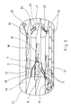
- the Fig. 2 shows a perspective view of the device according to the invention for the Kranzheimschmür according to Fig. 1 ,
- the device has a measured value recording 6 with a magnetic field detector 7, a Inclination detector 8, an acceleration detector 9, and a data processing device 10 with integrated data memory on.
- the measured value recording 6 is connected via supply cable 11 to a power supply 12.
- the power supply 12 has a current supply circuit 13 and four interconnected energy storage 14.
- the measured value recording 6 is connected via data transmission cable 15 to a communication device 16.
- the communication device 16 has a radio signal transmitter 17 and a light signal transmitter 18.
- the light signal transmitter 18 is connected via a glass fiber line 19 to a connection socket 20, which is arranged in a wall of a measured value recording 6, the power supply 12 and the communication device 16 surrounding housing 21.
- the housing 21 has a charging connection 22, which is connected via a charging cable 23 to the power supply 12 and via a data transmission cable 24 to the communication device 16.
Abstract
Description
Die Erfindung betrifft eine Vorrichtung zum Anbau an ein kabelgebundenes Unterwassergerät, insbesondere an einen Kranzwasserschöpfer, mit wenigstens einer Messwertaufnahme. Weiterhin betrifft die Erfindung einen Kranzwasserschöpfer mit wenigstens einer Messwertaufnahme und genau einem Anschlagmittel für ein lastaufnehmendes Kabel.The invention relates to a device for attachment to a wired underwater device, in particular to a Kranzwasserschöpfer, with at least one measured value recording. Furthermore, the invention relates to a Kranzwasserschöpfer with at least one measured value recording and exactly one stop means for a load-bearing cable.
Um den Verlust der überaus werthaltigen Unterwassergeräte zu vermeiden, ist es bekannt, das Kabel um ein beschädigtes Ende einzukürzen. Nachfolgend wird das kabelgebundene Unterwassergerät wieder mit dem eingekürzten Kabel verbunden. Diese Verbindung wird als Terminierung bezeichnet. Zur Terminierung gehört die Herstellung lastaufnehmender Anschlüsse, welche regelmäßig die äußeren Litzenschichten des Kabels ausbilden und die Herstellung informations- und energieführender Anschlüsse, welche regelmäßig im Inneren des Kabels verlaufen. So genannte torsionsfreie Kabel weisen gegenläufig spiralförmig gewickelte Litzenschichten auf, so dass sich bei Zugbelastung von den Litzenschichten induzierte Drehmomente gegeneinander aufheben. Wird ein Kabel terminiert, kommt es regelmäßig zu Spannungsdifferenzen zwischen den einzelnen Litzenschichten. Wird das Kabel dann zum ersten Mal belastet, tragen die Litzenschichten nunmehr unterschiedlich zur Lastaufnahme des Kabels bei, so dass die Tragfähigkeit des Kabels insgesamt vermindert ist und zusätzlich schädliche Drehmomente auftreten können. Um Spannungsdifferenzen zwischen den einzelnen Litzenschichten abzubauen, ist es bekannt, das Kabel vor seinem bestimmungsgemäßen Gebrauch mit einer Solllast auszuhängen. Das Aushängen erfolgt dabei auf der Basis von Erfahrungswerten, da in der Tiefe des Meeres nicht feststellbar ist, ob, wie schnell und wie lange die Solllast am Kabel dreht. Ein weiteres Problem besteht darin, dass das Kabel beim Hieven anders belastet wird als beim Fieren des Unterwassergerätes. Beim Fieren vermindert der Strömungswiderstand die vom Kabel aufzunehmende Last, und beim Hieven vergrößert der Strömungswiderstand die vom Kabel aufzunehmende Last. Kabel mit spiralförmig gewickelter Oberflächenstruktur haben ferner die Eigenschaft, dass durch Reibung in der Windenmechanik ebenfalls schädliche Drehmomente erzeugt werden. Außerdem kann sich durch das Anströmen eines asymmetrisch konstruierten Unterwassergerätes ähnlich eines Propellers ein Drehmoment ergeben, welches das Unterwassergerät in Drehung versetzt und das Kabel verdreht. Insbesondere beim Hieven können derartige Verdrehungen zu ernsthaften Beschädigungen des Kabels auf der Windentrommel führen. Außerdem besteht bei einer Verdrehung des Kabels stets die Gefahr, dass eine durch Seegang vom Schiff ausgeführte Senkgeschwindigkeit größer ist als die von der Seilwinde induzierte Hievgeschwindigkeit, so dass das Kabel zeitweise in einen lastfreien Zustand gerät und sich Schlaufen bilden können. Diese Gefahr besteht vor allem kurz vor dem an Bord holen des Unterwassergerätes. Bei Einsetzen einer erneuten Lastaufnahme wird das Kabel dann im Schlaufenbereich ernsthaft beschädigt. Ein Teil der Litzenschichten wird dabei irreversibel gestreckt ein anderer ebenso irreversibel überdreht, so dass der betreffende Kabelabschnitt entfernt und das Kabel neu terminiert werden muss. Bei bekannten Vorrichtungen weist die Messwertaufnahme beispielsweise zur Temperatur- und Tiefenmessung geeignete Messwertaufnahmen auf, die jedoch nicht dazu geeignet sind, Schädigungen des Kabels zu vermeiden.To avoid the loss of very valuable underwater equipment, it is known to cut the cable to a damaged end. Subsequently, the wired underwater device is reconnected to the shortened cable. This connection is called termination. Termination includes the production of load-bearing connections, which regularly form the outer strands of the cable and the production of information and energy-carrying connections, which run regularly inside the cable. So-called torsion-free cables have oppositely spirally wound strand layers, so that with tensile loading of the strand layers induced torques cancel each other. If a cable is terminated, voltage differences occur regularly between the individual strands. If the cable is then loaded for the first time, the strand layers now contribute differently to the load absorption of the cable, so that the carrying capacity of the cable as a whole is reduced and, in addition, damaging torques can occur. In order to reduce voltage differences between the individual layers of strands, it is known to unhook the cable before its intended use with a desired load. Hanging out takes place on the basis of empirical values, as in depth the sea can not determine whether, how fast and how long the target load on the cable turns. Another problem is that the cable is subjected to a different load when hoisting than when the underwater device is being fished. When flying, the flow resistance reduces the load to be absorbed by the cable, and when hoisted, the flow resistance increases the load to be absorbed by the cable. Cables with a spirally wound surface structure also have the property that due to friction in the winch mechanism also harmful torques are generated. In addition, the flow of an asymmetrically constructed underwater device similar to a propeller may result in a torque which causes the underwater device to rotate and twist the cable. Especially when lifting, such twists can lead to serious damage to the cable on the winch drum. In addition, with a rotation of the cable there is always the danger that a lowering speed carried out by the ship from the ship is greater than the hoisting speed induced by the winch, so that the cable temporarily becomes in a load-free state and can form loops. This danger is especially close to getting on board the underwater device. If you re-load, the cable will be seriously damaged in the loop area. One part of the Litzenschichten is irreversibly stretched another just as irreversible overrun, so that the cable section in question removed and the cable must be rescheduled. In known devices, the measured value recording, for example, for temperature and depth measurement suitable measured value recordings, which are not suitable, however, to avoid damage to the cable.
Der Erfindung liegt daher die Aufgabe zugrunde, eine Vorrichtung der eingangsgenannten Gattung aufzuzeigen, mit deren Messwertaufnahme Schädigungen des Kabels nachhaltig vermieden sind.The invention is therefore based on the object to show a device of the type mentioned, with the measured value recording damage to the cable are permanently avoided.
Diese Aufgabe ist erfindungsgemäß durch eine Vorrichtung mit den Merkmalen des Patentanspruches 1 sowie durch einen Kranzwasserschöpfer mit den Merkmalen des Patentanspruches 15 gelöst. Vorteilhafte Weiterbildungen der Erfindung sind in den auf den Patentanspruch 1 rückbezogenen Unteransprüchen 2 bis 14 angegeben.This object is achieved by a device having the features of
Die erfindungsgemäße Vorrichtung zum Anbau an ein kabelgebundenes Unterwassergerät zeichnet sich dadurch aus, dass mit der Messwertaufnahme wenigstens eine Lagebestimmungseinrichtung ausgebildet ist, und dass mit der Messwertaufnahme wenigstens eine Bewegungsbestimmungseinrichtung ausgebildet ist. Die Lagebestimmungseinrichtung dient einerseits der Bestimmung des Ortes des Unterwassergerätes in Bezug auf einen Fixpunkt, beispielsweise in Bezug auf ein das kabelgebundene Unterwassergerät zu Wasser lassendes Forschungsschiff, und andererseits der Bestimmung der Ausrichtung des Unterwassergerätes in Bezug auf seine eigenen geometrischen Abmessungen, beispielsweise in Bezug auf eine am Unterwassergerät definierte Hauptachse oder Hauptebene. Die Bewegungsbestimmungseinrichtung dient hingegen der Bestimmung translatorischer Bewegungen in Bezug auf die Bewegungsbahn des Unterwassergerätes sowie der Bestimmung rotatorischer Bewegungen in Bezug auf einen zentralen Punkt des Unterwassergerätes. Gemeinsam sind Lagebestimmungseinrichtung und Bewegungsbestimmungseinrichtung dazu geeignet, komplexe Bewegungsabläufe zu erfassen. Auf diese Weise können Schädigungen des Kabels hervorrufende Betriebssituationen kontrolliert vermieden werden. Mit der verbesserten Kenntnis über das Lage- und Bewegungsverhalten des Unterwassergerätes können andere von der Messwertaufnahme aufgenommene Messwerte als fehlerhaft erkannt und gegebenenfalls korrigiert oder verworfen werden.The device according to the invention for attachment to a wired underwater device is characterized in that at least one position determining device is formed with the measured value recording, and that at least one motion determination device is formed with the measured value recording. The attitude determination device serves on the one hand to determine the location of the underwater device with respect to a fixed point, for example with respect to a research vessel leaving the wired underwater device, and on the other hand to determine the orientation of the underwater device with respect to its own geometric dimensions, for example with respect to one the main axis or main plane defined on the underwater device. By contrast, the movement determination device is used to determine translational movements with respect to the movement path of the underwater device and the determination of rotational movements with respect to a central point of the underwater device. Together, position determination device and movement determination device are suitable for detecting complex movement sequences. In this way, damage to the cable causing operating situations can be controlled avoided. With the improved knowledge of the position and movement behavior of the underwater device, other measured values recorded by the measured value recording can be recognized as defective and, if necessary, corrected or rejected.
Nach einer ersten Weiterbildung der Erfindung weist die Lagebestimmungseinrichtung wenigstens einen Magnetfelddetektor auf. Dieser weist vorzugsweise in drei Raumrichtungen wirkende Sensoren auf, mit denen die Neigung und Richtung relativ zum Magnetfeld der Erde ermittelbar ist.According to a first development of the invention, the position determination device has at least one magnetic field detector. This preferably has sensors acting in three spatial directions, with which the inclination and direction relative to the magnetic field of the earth can be determined.
Nach einer nächsten Weiterbildung der Erfindung weist die Lagebestimmungseinrichtung wenigstens ein Barometer auf. Das Barometer dient insbesondere der Bestimmung der vertikalen Position des Unterwassergerätes, vorzugsweise in Bezug auf den mittleren Meeresspiegel.According to a next development of the invention, the position-determining device has at least one barometer. The barometer is used in particular the determination of the vertical position of the underwater device, preferably in relation to the mean sea level.
Um unerwünschte Schräglagen des Unterwassergerätes zu detektieren, weist die Lagebestimmungseinrichtung wenigstens einen Neigungsdetektor auf. Dieser dient vorzugsweise der Bestimmung einer Winkelabweichung zwischen einer am Unterwassergerät definierten Hauptebene und einer geräteunabhängigen Bezugsebene, beispielsweise einer Horizontalebene.In order to detect undesired inclinations of the underwater device, the position determination device has at least one inclination detector. This preferably serves to determine an angular deviation between a main plane defined on the underwater device and a device-independent reference plane, for example a horizontal plane.
Nach einer anderen Weiterbildung der Erfindung weist die Bewegungsbestimmungseinrichtung wenigstens einen Beschleunigungsdetektor auf. Der Beschleunigungsdetektor misst die auf eine definierte Testmasse wirkende Trägheitskraft, dessen Wert sich proportional zur Beschleunigung verhält. Vorzugsweise weist die Bewegungsbestimmungseinrichtung jedoch drei Beschleunigungsdetektoren auf, die jeweils in einem Winkel von 90° zueinander angeordnet sind. Auf diese Weise können mit dem Beschleunigungsdetektor in beliebigen Richtungen wirkende Linearbeschleunigungen gemessen werden.According to another development of the invention, the movement determination device has at least one acceleration detector. The acceleration detector measures the inertial force acting on a defined test mass whose value is proportional to the acceleration. Preferably, however, the motion determination device has three acceleration detectors, which are each arranged at an angle of 90 ° to each other. In this way, with the acceleration detector in any direction acting linear accelerations can be measured.
In Kenntnis der von dem Beschleunigungsdetektor gelieferten Beschleunigungswerte sowie der anfänglich von der Seilwinde induzierten Fiergeschwindigkeit können durch einfache Integration die linearen Geschwindigkeiten und durch zweifache Integration der Beschleunigungswerte die in allen drei Raumrichtungen zurückgelegten Wegstrecken bestimmt werden. Für die Integration der Beschleunigungswerte weist die Bewegungsbestimmungseinrichtung wenigstens ein Zeitmessglied auf.Knowing the acceleration values provided by the acceleration detector and the winch speed initially induced by the winch, the linear velocities can be determined by simple integration, and by integrating the acceleration values twice, the distances traveled in all three spatial directions can be determined. For the integration of the acceleration values, the motion determination device has at least one timing element.
Zur Übertragung der von der Lagebestimmungseinrichtung und der Bewegungsbestimmungseinrichtung gelieferten Daten an die Wasseroberfläche, insbesondere an ein dort befindliches Forschungsschiff weist die Messwertaufnahme wenigstens einen Funksignalgeber auf. Mit dem Funksignalgeber kann vorteilhaft auf korrosionsgefährdete galvanische Verbindungen zwischen der erfindungsgemäßen Vorrichtung und dem kabelgebundenen Unterwassergerät verzichtet werden.To transmit the data supplied by the position-determining device and the movement-determining device to the water surface, in particular to a research ship located there, the measured-value recording has at least one radio signal transmitter. With the radio signal transmitter can be advantageous to corrosion-prone galvanic Connections between the device according to the invention and the wired underwater device are dispensed with.
Nach einer nächsten Weiterbildung der Erfindung weist die Messwertaufnahme wenigstens einen Strömungsmesser auf. Dieser kann je nach Ausrichtung und Anordnung sowohl zur Messung der Meeresströmungen als auch zur Messung der Hief-, Fier- oder Winkelgeschwindigkeiten eingesetzt werden. Der Strömungsmesser kann sowohl Bestandteil der Lagebestimmungseinrichtung als auch Bestandteil der Bewegungsbestimmungseinrichtung sein.According to a next development of the invention, the measured value recording has at least one flow meter. This can be used depending on the orientation and arrangement both for measuring the ocean currents as well as for measuring the Hief, Fier or angular velocities. The flow meter can be both part of the orientation device and part of the motion determination device.
Nach einer anderen Weiterbildung der Erfindung weist die Messwertaufnahme einen akustischen Entfernungsmesser auf. Dieser kann insbesondere unter Anwendung des Dopplereffektes Bestandteil der Bewegungsbestimmungseinrichtung sein. Grundsätzlich ist es jedoch ebenso denkbar, den Entfernungsmesser zur Bestimmung des Ortes des Unterwassergerätes einzusetzen.According to another embodiment of the invention, the measured value recording on an acoustic rangefinder. This can be part of the motion-determining device, in particular using the Doppler effect. In principle, however, it is also conceivable to use the rangefinder to determine the location of the underwater device.
Nach einer besonders vorteilhaften Weiterbildung der Erfindung ist die Messwertaufnahme an eine Datenverarbeitungseinrichtung angeschlossen, wobei die Messwerteinrichtung und die Datenverarbeitungseinrichtung gemeinsam in einem Gehäuse verkapselt sind. Vorzugsweise weist die Datenverarbeitungseinrichtung einen Datenspeicher auf, mit welchem aus den Messwerten erzeugte Daten besonders zuverlässig gegen unbeabsichtigte Datenverluste zwischengespeichert und gesichert werden können. Eine hochdruckfeste Ausbildung des Gehäuses macht die erfindungsgemäße Vorrichtung auch für Tiefwassereinsätze außerhalb von Schelfbereichen geeignet. Besonders bevorzugt ist vorgesehen, die einzelnen Komponenten der Messwertaufnahme mittels einer Vergussmasse zu einem Modul fest miteinander zu vergießen. Bei einem derart ausgebildeten Modul übernimmt die Vergussmasse die Funktion des Gehäuses.According to a particularly advantageous embodiment of the invention, the measured value recording is connected to a data processing device, wherein the measured value device and the data processing device are encapsulated together in a housing. Preferably, the data processing device has a data memory with which data generated from the measured values can be buffered and secured particularly reliably against unintentional data losses. A high pressure resistant design of the housing makes the device according to the invention also suitable for deep water operations outside of shelf areas. It is particularly preferred to firmly cast the individual components of the measured value recording by means of a potting compound to form a module. In a module designed in this way, the potting compound assumes the function of the housing.
Alternativ zu der Ausbildung eines hochdruckfesten Gehäuses wird vorgeschlagen, das Gehäuse mit einem Öl zu befüllen. Aufgrund der inkompressiblen Eigenschaften von Öl stellt sich im Inneren des Gehäuse der an der Gehäuseaußenseite anliegende Außendruck ein, so dass die vom Gehäuse aufzunehmenden Spannungen minimal klein sind.As an alternative to the formation of a high-pressure resistant housing, it is proposed to fill the housing with an oil. Due to the incompressible properties of oil, the external pressure applied to the outside of the housing sets in the interior of the housing, so that the voltages to be absorbed by the housing are minimally small.
Weiterhin ist vorgesehen, dass die Messwertaufnahme wenigstens einen im Gehäuse verkapselten Energiespeicher aufweist. Mit dem verkapselten Energiespeicher kann vorteilhaft auf korrosionsgefährdete galvanische Verbindungen zwischen der erfindungsgemäßen Vorrichtung und dem Unterwassergerät verzichtet werden. Als Energiespeicher werden beispielsweise Batterien oder Akkumulatoren eingesetzt.Furthermore, it is provided that the measured value recording has at least one energy store encapsulated in the housing. With the encapsulated energy storage can be dispensed with corrosion-prone galvanic connections between the device according to the invention and the underwater device advantageous. As energy storage batteries or accumulators, for example, are used.
Um den Wartungsaufwand für die erfindungsgemäße Vorrichtung so gering wie möglich zu halten, weist der Energiespeicher wenigstens einen im Gehäuse verkapselten Ladeanschluss auf. Auf diese Weise kann der Energiespeicher mit Energie nachgeladen werden, ohne das Gehäuse hierfür öffnen oder galvanische Leitungen durch die Gehäusewandungen hindurchführen zu müssen. Das Nachladen des Energiespeichers erfolgt beispielsweise induktiv über den Aufbau elektrischer Magnetfelder.In order to keep the maintenance costs for the device according to the invention as low as possible, the energy store has at least one charge connection encapsulated in the housing. In this way, the energy storage can be recharged with energy without having to open the housing for this purpose or to have to lead galvanic lines through the housing walls. The recharging of the energy storage is done, for example, inductively on the construction of electrical magnetic fields.
Zur Befestigung der erfindungsgemäßen Vorrichtung an ein kabelgebundenes Unterwassergerät weist das Gehäuse mit dem Unterwassergerät, insbesondere mit dem Gestell eines Kranzwasserschöpfers, zusammenwirkende Befestigungsstrukturen auf. Diese weisen vorzugsweise Verstellmöglichkeiten auf, mit denen die Befestigungsstrukturen an die Gestelle verschiedener handelsverfügbarer Kranzwasserschöpfer angepasst werden können. Um die erfindungsgemäße Vorrichtung im Wechsel an mehreren Kranzwasserschöpfern einsetzen zu können, sind mit den Befestigungsstrukturen mit Vorteil lösbare Verbindungen, insbesondere nach Art von Schnellverschlüssen fungierende Verbindungen ausgebildet.For attachment of the device according to the invention to a wired underwater device, the housing with the underwater device, in particular with the frame of a Kranzwasserschöpfers, cooperating mounting structures. These preferably have adjustment options with which the attachment structures can be adapted to the racks of various commercially available wreath water creator. In order to be able to use the device according to the invention in alternation with a plurality of crown-type water creators, connections releasably with the fastening structures are advantageously formed, in particular connections which act in the manner of quick-release closures.
Der erfindungsgemäße Kranzwasserschöpfer zeichnet sich in analoger Weise zur erfindungsgemäßen Vorrichtung ebenfalls dadurch aus, dass mit seiner Messwertaufnahme wenigstens eine Lagebestimmungseinrichtung sowie wenigstens eine Bewegungsbestimmungseinrichtung ausgebildet ist. Dabei besteht zum einen die Möglichkeit, die Lage- und Bewegungsbestimmungseinrichtung in einer Baueinheit zusammenzufassen und diese Baueinheit in lösbarer oder unlösbarer Weise am Gestell des Kranzwasserschöpfers anzuordnen. Zum anderen besteht jedoch auch die Möglichkeit, Lage- und Bewegungsbestimmungseinrichtung konstruktiv in die vorhandenen Strukturen handelsverfügbarer Kranzwasserschöpfer zu integrieren.The wreath coater according to the invention is likewise distinguished in a manner analogous to the device according to the invention in that at least one position-determining device and at least one movement-determining device are formed with its measured value recording. It is on the one hand the ability to summarize the position and motion determination device in a unit and to arrange this unit in a detachable or non-detachable manner on the frame of the Kranzwasserschöpfers. On the other hand, however, there is also the possibility of structurally and position-determining device to integrate into the existing structures commercially available Kranzwasserschöpfer.
Ein Ausführungsbeispiel der Erfindung, aus dem sich weitere erfinderische Merkmale ergeben, ist in der Zeichnung dargestellt. Es zeigen:
- Fig. 1:
- ein kabelgebundenes Unterwassergerät in einem schematisch dargestellten Anwendungsbeispiel;
- Fig. 2:
- eine perspektivische Ansicht der erfindungsgemäßen Vorrichtung für das kabelgebundene Unterwassergerät gemäß
Fig. 1 .
- Fig. 1:
- a wired underwater device in a schematically illustrated application example;
- Fig. 2:
- a perspective view of the device according to the invention for the wired underwater device according to
Fig. 1 ,
Die
Die
Claims (15)
dadurch gekennzeichnet,
dass mit der Messwertaufnahme (2) wenigstens eine Lagebestimmungseinrichtung ausgebildet ist, und
dass mit der Messwertaufnahme (2) wenigstens eine Bewegungsbestimmungseinrichtung ausgebildet ist.Device for attachment to a wired underwater device, in particular to a wreath water creator, with at least one measured value recording,
characterized,
that with the measured value recording (2) at least one position determining device is formed, and
in that at least one movement determination device is formed with the measured value recording (2).
dass mit der Messwertaufnahme (2) wenigstens eine Lagebestimmungseinrichtung ausgebildet ist, und
dass mit der Messwertaufnahme (2) wenigstens eine Bewegungsbestimmungseinrichtung ausgebildet ist.Wreath water maker with at least one measured value recording and exactly one stop means for a load-receiving cable, in particular for receiving a device according to one of the claims 1 to 14, characterized
that with the measured value recording (2) at least one position determining device is formed, and
in that at least one movement determination device is formed with the measured value recording (2).
Applications Claiming Priority (1)
| Application Number | Priority Date | Filing Date | Title |
|---|---|---|---|
| DE200910039192 DE102009039192A1 (en) | 2009-08-28 | 2009-08-28 | Device for attachment to a wired underwater device |
Publications (2)
| Publication Number | Publication Date |
|---|---|
| EP2299254A2 true EP2299254A2 (en) | 2011-03-23 |
| EP2299254A3 EP2299254A3 (en) | 2014-05-07 |
Family
ID=43230470
Family Applications (1)
| Application Number | Title | Priority Date | Filing Date |
|---|---|---|---|
| EP10008884.8A Withdrawn EP2299254A3 (en) | 2009-08-28 | 2010-08-26 | Device for attachment to an underwater device attached to a cable |
Country Status (2)
| Country | Link |
|---|---|
| EP (1) | EP2299254A3 (en) |
| DE (1) | DE102009039192A1 (en) |
Cited By (4)
| Publication number | Priority date | Publication date | Assignee | Title |
|---|---|---|---|---|
| CN107479601A (en) * | 2017-09-18 | 2017-12-15 | 中国船舶科学研究中心(中国船舶重工集团公司第七0二研究所) | A kind of automatic deploying and retracting cable monitoring system and method for ROV umbilical cables winches |
| CN109632384A (en) * | 2018-12-21 | 2019-04-16 | 上海大学 | A kind of unmanned catamaran of water quality sampling and its method of sampling |
| CN113252406A (en) * | 2021-05-31 | 2021-08-13 | 中国极地研究中心 | Multilayer water sampling method and water sampling device |
| CN114954804A (en) * | 2022-05-13 | 2022-08-30 | 深圳市智慧海洋科技有限公司 | Deployment protection method, deployment protection device, acoustic releaser and storage medium |
Families Citing this family (1)
| Publication number | Priority date | Publication date | Assignee | Title |
|---|---|---|---|---|
| EP2549246A1 (en) * | 2011-07-21 | 2013-01-23 | Vetco Gray Controls Limited | An electronics module for use subsea |
Family Cites Families (10)
| Publication number | Priority date | Publication date | Assignee | Title |
|---|---|---|---|---|
| US3841156A (en) * | 1972-12-14 | 1974-10-15 | Gulf Research Development Co | Combined depth indicator and water sampler |
| US5691903A (en) * | 1995-09-08 | 1997-11-25 | The United States Of America As Represented By The Secretary Of The Navy | Integrated cable navigation and control system |
| US5894450A (en) * | 1997-04-15 | 1999-04-13 | Massachusetts Institute Of Technology | Mobile underwater arrays |
| DE10064419C2 (en) * | 2000-12-21 | 2003-10-30 | I For T Gmbh | Motion and tilt monitoring device |
| US6791490B2 (en) * | 2001-03-30 | 2004-09-14 | Joseph David King | Integrated dive flag/float and GPS navigation system for scuba divers |
| US6807127B2 (en) * | 2001-11-19 | 2004-10-19 | John F. McGeever, Jr. | Navigational device for an underwater diver |
| US7000903B2 (en) * | 2003-03-24 | 2006-02-21 | Oceaneering International, Inc. | Wireline subsea metering head and method of use |
| US7316196B2 (en) * | 2005-03-18 | 2008-01-08 | Shell Oil Company | Method and apparatus for handling mooring lines |
| US8437979B2 (en) * | 2007-01-20 | 2013-05-07 | Kcf Technologies, Inc. | Smart tether system for underwater navigation and cable shape measurement |
| GB2450158B (en) * | 2007-06-15 | 2009-06-03 | Ohm Ltd | Electromagnetic detector for marine surveying |
-
2009
- 2009-08-28 DE DE200910039192 patent/DE102009039192A1/en not_active Withdrawn
-
2010
- 2010-08-26 EP EP10008884.8A patent/EP2299254A3/en not_active Withdrawn
Non-Patent Citations (1)
| Title |
|---|
| None |
Cited By (5)
| Publication number | Priority date | Publication date | Assignee | Title |
|---|---|---|---|---|
| CN107479601A (en) * | 2017-09-18 | 2017-12-15 | 中国船舶科学研究中心(中国船舶重工集团公司第七0二研究所) | A kind of automatic deploying and retracting cable monitoring system and method for ROV umbilical cables winches |
| CN109632384A (en) * | 2018-12-21 | 2019-04-16 | 上海大学 | A kind of unmanned catamaran of water quality sampling and its method of sampling |
| CN113252406A (en) * | 2021-05-31 | 2021-08-13 | 中国极地研究中心 | Multilayer water sampling method and water sampling device |
| CN114954804A (en) * | 2022-05-13 | 2022-08-30 | 深圳市智慧海洋科技有限公司 | Deployment protection method, deployment protection device, acoustic releaser and storage medium |
| CN114954804B (en) * | 2022-05-13 | 2023-11-10 | 深圳市智慧海洋科技有限公司 | Arrangement protection method, arrangement protection device, acoustic releaser and storage medium |
Also Published As
| Publication number | Publication date |
|---|---|
| EP2299254A3 (en) | 2014-05-07 |
| DE102009039192A1 (en) | 2011-04-07 |
Similar Documents
| Publication | Publication Date | Title |
|---|---|---|
| DE69832351T2 (en) | Internal devices for an underwater cable arrangement | |
| EP2299254A2 (en) | Device for attachment to an underwater device attached to a cable | |
| EP3102523B1 (en) | Measuring system and measuring method for testing the catching device of an elevator | |
| DE102014215346B4 (en) | Support system for a measuring device for monitoring a hydraulic structure under water | |
| US10944248B2 (en) | Smart hoist | |
| CN108387713A (en) | A kind of bottom sediment test device, injection system and injection method | |
| DE2720273A1 (en) | METHOD AND DEVICE FOR DETERMINING AND REGISTERING MEASURED VALUES OF A DEEP HOLE | |
| CH659981A5 (en) | Method for monitoring the drift of lying at anchor vessel and device for implementing the procedure. | |
| DE112013002210T5 (en) | Device and method in connection with a crane pulley | |
| CH707573A1 (en) | Method and system for determining the displacement of an anchor. | |
| WO2013034607A1 (en) | Method for determining the inclination of a tower | |
| WO2020002312A1 (en) | Ultrasonic measuring device | |
| CN110979672B (en) | Transient electromagnetic emission loop wiring device and method carried by unmanned aerial vehicle | |
| CN110512585B (en) | Free-fall type hole pressure dynamic sounding device for evaluating characteristics of seabed shallow soil | |
| DE102016003926B4 (en) | Underwater probe | |
| Ageron et al. | Studies of a full-scale mechanical prototype line for the ANTARES neutrino telescope and tests of a prototype instrument for deep-sea acoustic measurements | |
| CN207991944U (en) | A kind of horizontal pull experimental rig applied to slope pile foundation | |
| WO2010051955A1 (en) | Electro-optical inclination measurement system | |
| DE102011121439A1 (en) | Measuring device for detecting load of rotor blade of rotor of wind turbine, has sensor obtaining rotational speed about longitudinal axis of rotor blade and transmitting unit transmitting measurement signal to control unit | |
| DE102020214695B4 (en) | Device for determining the fill level of a liquid in a container | |
| DE19825887A1 (en) | Underwater towing antenna | |
| DE4221327C2 (en) | Depth control unit for an underwater measuring cable with an outer cable sheath and a hydrophone | |
| DE102013008621A1 (en) | Apparatus and method for supervised production of a high pressure injection body | |
| DE2748681C2 (en) | Method for determining the position of underwater drilling rigs | |
| CN110884615A (en) | Submerged buoy breaking protection device |
Legal Events
| Date | Code | Title | Description |
|---|---|---|---|
| PUAI | Public reference made under article 153(3) epc to a published international application that has entered the european phase |
Free format text: ORIGINAL CODE: 0009012 |
|
| AK | Designated contracting states |
Kind code of ref document: A2 Designated state(s): AL AT BE BG CH CY CZ DE DK EE ES FI FR GB GR HR HU IE IS IT LI LT LU LV MC MK MT NL NO PL PT RO SE SI SK SM TR |
|
| AX | Request for extension of the european patent |
Extension state: BA ME RS |
|
| RAP1 | Party data changed (applicant data changed or rights of an application transferred) |
Owner name: OPTIMARE HOLDING GMBH |
|
| RAP1 | Party data changed (applicant data changed or rights of an application transferred) |
Owner name: OPTIMARE SYSTEMS GMBH |
|
| PUAL | Search report despatched |
Free format text: ORIGINAL CODE: 0009013 |
|
| AK | Designated contracting states |
Kind code of ref document: A3 Designated state(s): AL AT BE BG CH CY CZ DE DK EE ES FI FR GB GR HR HU IE IS IT LI LT LU LV MC MK MT NL NO PL PT RO SE SI SK SM TR |
|
| AX | Request for extension of the european patent |
Extension state: BA ME RS |
|
| RIC1 | Information provided on ipc code assigned before grant |
Ipc: G01N 1/12 20060101AFI20140403BHEP Ipc: G01N 1/16 20060101ALI20140403BHEP |
|
| STAA | Information on the status of an ep patent application or granted ep patent |
Free format text: STATUS: THE APPLICATION IS DEEMED TO BE WITHDRAWN |
|
| 18D | Application deemed to be withdrawn |
Effective date: 20141108 |