EP2299244A1 - Clutch position sensor for vehicle transmisssion - Google Patents
Clutch position sensor for vehicle transmisssion Download PDFInfo
- Publication number
- EP2299244A1 EP2299244A1 EP10175471A EP10175471A EP2299244A1 EP 2299244 A1 EP2299244 A1 EP 2299244A1 EP 10175471 A EP10175471 A EP 10175471A EP 10175471 A EP10175471 A EP 10175471A EP 2299244 A1 EP2299244 A1 EP 2299244A1
- Authority
- EP
- European Patent Office
- Prior art keywords
- sensor
- flux concentrator
- signals
- casing
- transmission
- Prior art date
- Legal status (The legal status is an assumption and is not a legal conclusion. Google has not performed a legal analysis and makes no representation as to the accuracy of the status listed.)
- Withdrawn
Links
Images

Classifications
-
- F—MECHANICAL ENGINEERING; LIGHTING; HEATING; WEAPONS; BLASTING
- F16—ENGINEERING ELEMENTS AND UNITS; GENERAL MEASURES FOR PRODUCING AND MAINTAINING EFFECTIVE FUNCTIONING OF MACHINES OR INSTALLATIONS; THERMAL INSULATION IN GENERAL
- F16D—COUPLINGS FOR TRANSMITTING ROTATION; CLUTCHES; BRAKES
- F16D48/00—External control of clutches
- F16D48/06—Control by electric or electronic means, e.g. of fluid pressure
-
- F—MECHANICAL ENGINEERING; LIGHTING; HEATING; WEAPONS; BLASTING
- F16—ENGINEERING ELEMENTS AND UNITS; GENERAL MEASURES FOR PRODUCING AND MAINTAINING EFFECTIVE FUNCTIONING OF MACHINES OR INSTALLATIONS; THERMAL INSULATION IN GENERAL
- F16D—COUPLINGS FOR TRANSMITTING ROTATION; CLUTCHES; BRAKES
- F16D25/00—Fluid-actuated clutches
- F16D25/08—Fluid-actuated clutches with fluid-actuated member not rotating with a clutching member
-
- G—PHYSICS
- G01—MEASURING; TESTING
- G01D—MEASURING NOT SPECIALLY ADAPTED FOR A SPECIFIC VARIABLE; ARRANGEMENTS FOR MEASURING TWO OR MORE VARIABLES NOT COVERED IN A SINGLE OTHER SUBCLASS; TARIFF METERING APPARATUS; MEASURING OR TESTING NOT OTHERWISE PROVIDED FOR
- G01D5/00—Mechanical means for transferring the output of a sensing member; Means for converting the output of a sensing member to another variable where the form or nature of the sensing member does not constrain the means for converting; Transducers not specially adapted for a specific variable
- G01D5/12—Mechanical means for transferring the output of a sensing member; Means for converting the output of a sensing member to another variable where the form or nature of the sensing member does not constrain the means for converting; Transducers not specially adapted for a specific variable using electric or magnetic means
- G01D5/14—Mechanical means for transferring the output of a sensing member; Means for converting the output of a sensing member to another variable where the form or nature of the sensing member does not constrain the means for converting; Transducers not specially adapted for a specific variable using electric or magnetic means influencing the magnitude of a current or voltage
- G01D5/142—Mechanical means for transferring the output of a sensing member; Means for converting the output of a sensing member to another variable where the form or nature of the sensing member does not constrain the means for converting; Transducers not specially adapted for a specific variable using electric or magnetic means influencing the magnitude of a current or voltage using Hall-effect devices
- G01D5/145—Mechanical means for transferring the output of a sensing member; Means for converting the output of a sensing member to another variable where the form or nature of the sensing member does not constrain the means for converting; Transducers not specially adapted for a specific variable using electric or magnetic means influencing the magnitude of a current or voltage using Hall-effect devices influenced by the relative movement between the Hall device and magnetic fields
-
- F—MECHANICAL ENGINEERING; LIGHTING; HEATING; WEAPONS; BLASTING
- F16—ENGINEERING ELEMENTS AND UNITS; GENERAL MEASURES FOR PRODUCING AND MAINTAINING EFFECTIVE FUNCTIONING OF MACHINES OR INSTALLATIONS; THERMAL INSULATION IN GENERAL
- F16D—COUPLINGS FOR TRANSMITTING ROTATION; CLUTCHES; BRAKES
- F16D25/00—Fluid-actuated clutches
- F16D25/08—Fluid-actuated clutches with fluid-actuated member not rotating with a clutching member
- F16D2025/081—Hydraulic devices that initiate movement of pistons in secondary cylinders for actuating clutches, i.e. primary cylinders
-
- F—MECHANICAL ENGINEERING; LIGHTING; HEATING; WEAPONS; BLASTING
- F16—ENGINEERING ELEMENTS AND UNITS; GENERAL MEASURES FOR PRODUCING AND MAINTAINING EFFECTIVE FUNCTIONING OF MACHINES OR INSTALLATIONS; THERMAL INSULATION IN GENERAL
- F16D—COUPLINGS FOR TRANSMITTING ROTATION; CLUTCHES; BRAKES
- F16D2300/00—Special features for couplings or clutches
- F16D2300/18—Sensors; Details or arrangements thereof
-
- F—MECHANICAL ENGINEERING; LIGHTING; HEATING; WEAPONS; BLASTING
- F16—ENGINEERING ELEMENTS AND UNITS; GENERAL MEASURES FOR PRODUCING AND MAINTAINING EFFECTIVE FUNCTIONING OF MACHINES OR INSTALLATIONS; THERMAL INSULATION IN GENERAL
- F16D—COUPLINGS FOR TRANSMITTING ROTATION; CLUTCHES; BRAKES
- F16D2300/00—Special features for couplings or clutches
- F16D2300/26—Cover or bell housings; Details or arrangements thereof
-
- F—MECHANICAL ENGINEERING; LIGHTING; HEATING; WEAPONS; BLASTING
- F16—ENGINEERING ELEMENTS AND UNITS; GENERAL MEASURES FOR PRODUCING AND MAINTAINING EFFECTIVE FUNCTIONING OF MACHINES OR INSTALLATIONS; THERMAL INSULATION IN GENERAL
- F16D—COUPLINGS FOR TRANSMITTING ROTATION; CLUTCHES; BRAKES
- F16D2500/00—External control of clutches by electric or electronic means
- F16D2500/30—Signal inputs
- F16D2500/302—Signal inputs from the actuator
- F16D2500/3026—Stroke
-
- F—MECHANICAL ENGINEERING; LIGHTING; HEATING; WEAPONS; BLASTING
- F16—ENGINEERING ELEMENTS AND UNITS; GENERAL MEASURES FOR PRODUCING AND MAINTAINING EFFECTIVE FUNCTIONING OF MACHINES OR INSTALLATIONS; THERMAL INSULATION IN GENERAL
- F16D—COUPLINGS FOR TRANSMITTING ROTATION; CLUTCHES; BRAKES
- F16D2500/00—External control of clutches by electric or electronic means
- F16D2500/50—Problem to be solved by the control system
- F16D2500/501—Relating the actuator
-
- G—PHYSICS
- G01—MEASURING; TESTING
- G01D—MEASURING NOT SPECIALLY ADAPTED FOR A SPECIFIC VARIABLE; ARRANGEMENTS FOR MEASURING TWO OR MORE VARIABLES NOT COVERED IN A SINGLE OTHER SUBCLASS; TARIFF METERING APPARATUS; MEASURING OR TESTING NOT OTHERWISE PROVIDED FOR
- G01D2205/00—Indexing scheme relating to details of means for transferring or converting the output of a sensing member
- G01D2205/40—Position sensors comprising arrangements for concentrating or redirecting magnetic flux
Definitions
- the present invention relates generally to clutch position sensors for automotive vehicle transmissions.
- Modem automotive vehicles employ an engine transmission system having gears of different sizes to transfer power produced by the vehicle's engine to the vehicle's wheels based on the speed at which the vehicle is traveling.
- the engine transmission system typically includes a clutch mechanism which may engage and disengage these gears.
- the clutch mechanism may be operated manually by the vehicle's driver, or automatically by the vehicle itself based on the speed at which the driver wishes to operate the vehicle.
- Current clutch-position sensing components utilize magnetic sensors.
- One advantage to using magnetic sensors is that the sensor need not be in physical contact with the object being sensed, thereby avoiding mechanical wear between the sensor and the object.
- actual linear clutch measurement accuracy may be compromised when the sensor is not in physical contact with the sensed object because of a necessary gap or tolerance that exists between the sensor and the object.
- current sensing systems addressing this problem use coils and certain application-specific integrated circuits which are relatively expensive.
- an apparatus has a magnet disposable inside an engine transmission casing and movable by an engine clutch mechanism in the casing as the engine clutch mechanism moves.
- a flux concentrator is disposable outside the engine transmission casing to concentrate magnetic flux from the magnet, and a first sensor is juxtaposed with the flux concentrator for generating a first signal in response to a magnetic field. Additionally, a second sensor is juxtaposed with the flux concentrator for generating a second signal in response to a magnetic field.
- a position determination circuit receives the first and second signals and based thereon outputs a signal representative of a linear position of the engine clutch mechanism.
- the flux concentrator is elongated and defines first and second ends, with the first sensor being juxtaposed with the first end and the second sensor being juxtaposed with the second end.
- a first magnetic booster and a second magnetic booster can be provided.
- the first sensor may be disposed between the first end of the flux concentrator and the first magnetic booster, and the second sensor may be disposed between the second end of the flux concentrator and the second magnetic booster.
- the flux concentrator can be made of a soft magnetic material.
- the magnet is disposed inside the transmission casing and is coupled to the engine clutch mechanism.
- the flux concentrator and sensors typically are disposed outside the casing.
- the flux concentrator tapers inwardly to the first and second ends as do the boosters.
- an apparatus has a position sensor disposed outside a transmission casing and bearing a distance within a tolerance from a moving part in the transmission whose position is sought to be measured with a desired degree of accuracy regardless of where in the tolerance the sensor is located relative to the part.
- the position sensor includes plural sensing elements whose individual outputs representing position of the part are affected by the location of the sensor within the tolerance.
- the sensor also includes a position determination member receiving the signals from the sensing elements and combining the signals in a way that produces a signal representative of the position of the part that is less affected by the location of the sensor within the tolerance than are the signals from the sensing elements.
- a method in another aspect, includes receiving first and second signals from first and second sensors, respectively.
- the signals represent a position of a moving part.
- the method includes determining a ratio in which a numerator is derived from only one of the signals, or from a difference between the signals, and the denominator is a sum derived from both of the signals. Position of the moving part is indicated using the ratio.
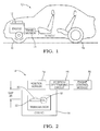
- Figure 1 is a schematic view of a vehicle that can use the present clutch position sensor
- Figure 2 is a schematic view of a transmission, showing parts related to present principles
- Figure 3 is a schematic view an example embodiment of the sensor
- Figure 4 is a perspective view of an example embodiment of the sensor.
- Figure 5 is a graph showing voltage ratios versus clutch positions.
- the present invention is intended for application in automotive transmission systems and will be described in that context. It is to be understood, however, that the present invention may also be applied to other applications and contexts requiring non-contact linear position sensors.
- the automotive vehicle 10 has an engine 12 and an engine transmission 14. It is to be understood that the engine transmission 14 has a clutch capable of engaging transmission gears by means known within the art. Further, the engine transmission 14 is understood to employ a clutch position sensor described further below.
- the vehicle 10 also has plural wheels 16 so that the vehicle 10 may be mobile.
- FIG. 1 a schematic view of an engine transmission is shown.
- the engine transmission 14 is surrounded by an engine transmission casing 16, the casing 16 being made of a metal such as aluminum (or any nonmagnetic material) in non-limiting embodiments. Additionally, the engine transmission 14 includes a clutch mechanism 18.
- a magnet 20 is also shown in Figure 2 .
- the magnet 20 is disposed inside the casing 16 and is coupled to the engine clutch mechanism 18.
- the magnet 20 can be particularly coupled to a moving part 22 of the clutch mechanism 18.
- the moving part 22 may be a transmission clutch component such as a piston that moves a transmission clutch in non-limiting embodiments.
- the clutch component may have a movement range in excess of 25 millimeters in non-limiting embodiments.
- the magnet 20 may be placed on any acceptable moving part of the clutch mechanism 18 as determined by those skilled in the art.
- a transmission clutch position sensor 24 is disposed outside the casing 16 and is capable of sensing a magnetic field generated by the magnet 20. It is to be understood that the sensor 24 is relatively inexpensive and preferably does not include a coil, including any type of electromagnetic coil. The sensor 24 will be described in greater detail in Figures 3 and 4 .
- the position sensor 24 disposed outside a transmission casing 16 bears a gap distance 26 within a tolerance from the moving part 22.
- the normal gap 26 may be anywhere from 5 millimeters up to 30 millimeters.
- the sensor 24 may still output relatively constant measurements of the relatively large linear position of the moving part 22 at particular times based on the magnetic field generated by the magnet 20 regardless of where in the few millimeters tolerance of the gap the sensor is disposed.
- the position sensor 24 may include plural sensing elements that will be functionally described in greater detail in Figures 3 and 4 .
- the position sensor 24 is electrically connected at least one position determining circuit 28.
- the circuit 28 receives signals from the position sensor 24 and outputs a signal to an engine control module 30 indicating the linear position of the engine clutch mechanism 18. The method of calculation for the linear position of the mechanism 18 will be described in greater detail below.
- the engine control module 30 is understood to be electronically connected to the circuit 28 and may use the linear position information in conjunction with vehicle operation in non-limiting embodiments to establish demanded clutch positions.
- a schematic view of an example embodiment of a position sensor is shown. It is to be understood that a sensor 32 may be disposable outside an engine transmission casing and is substantially similar in function and configuration to the sensor 24 described above. Thus, Figure 3 shows particular elements of a sensor 32 for the current embodiment.
- the sensor 32 has at least one elongated flux concentrator 34 which may concentrate magnetic flux generated by a magnet 36 coupled to a moving part inside a transmission casing, the magnet 36 being substantially similar in function and configuration to the magnet 20 described in Figure 2 .
- the flux concentrator 34 may be made of a soft magnetic material such as ferrite ceramic, magnet annealed NiFe, etc.
- Figure 3 also shows plural sensing elements 38 which are closely juxtaposed with respective ends 40 of the flux concentrator 34.
- the sensing elements may be, without limitation, Hall sensors.
- each of the sensing elements 38 is capable of generating a signal or output in response to a magnetic field generated by the magnet 36 and concentrated onto the sensors by the flux concentrator.
- the plural sensing elements 38 may each yield a signal or output representing the linear position a moving part, similar to the moving part 22 described in Figure 2 , which is measured based on the magnetic field created by movement of the magnet 36. Accordingly, the individual outputs are received by the position determination circuit, which combines the signals in a way (described below) that produces a signal representative of the actual position of a moving part that is relatively unaffected by the location of the sensor 32 within a gap or tolerance.
- the senor 32 may also have plural magnetic boosters 42 which have respective ends 44 facing each booster's respective sensing element 38 in non-limiting embodiments. Accordingly, each of the sensing elements 38 may be disposed between a respective end 40 of the flux concentrator 34 and a respective end 44 of a magnetic booster 42. The relative position of the sensing elements 38 between ends 40 and 44 will be described further in Figure 4 .
- FIG. 4 a perspective view of an example embodiment of the sensor 32 also described in Figure 3 is shown. From the perspective view shown in Figure 4 , it may be appreciated that the flux concentrator 34 tapers inwardly toward the ends 40. It may be further appreciated that the magnetic boosters 42 taper inwardly toward their respective ends 44 that face their respective sensing elements 38. These inward tapers may increase the ability of the sensing elements 38 to sense a magnetic field strength.
- the graph 46 shows magnetic field intensity ratios which are based on the magnetic field intensity from one position sensor divided by the sum of the magnetic field intensity from both sensors. Also, the ratio could be that the magnetic field intensity difference between the two sensors over the sum of the magnetic field intensity of both sensors.
- the ratios used in the graph 46 are determined by a numerator which is derived from only one of the signals of a position sensor or the difference between both sensors and a denominator which is the sum derived from both signal of the position sensors.
- This ratio may then be used to indicate the position of a moving part to within a certain degree of accuracy (preferably 3-5% of the actual position of the moving part) such as the piston of a clutch mechanism inside a vehicle transmission in non-limiting embodiments.
- the ratio thus allows an accurate measurement of the position of the moving part irrespective of where in the tolerance a position sensor may be, such as sensor 24 referenced in Figure 1 (i.e. despite a gap such as the gap 26 in Figure 1 ).
- the position indicated by the ratio may then be used by a vehicle, particularly by an engine control module in a vehicle, to control a subsequent position of the moving part in non-limiting embodiments.
- the graph shows voltage ratios ranging from 0 to 1.2 in the vertical column 48 and magnet positions ranging within a 50 millimeter range in the horizontal column 50.
- the graph line 52 represents the sensor output when the Hall sensors are 26mm from the magnet, whereas graph line 54, which is nearly coterminous with graph line 52, shows sensor output when the Hall sensors are 29mm from the magnet.
Landscapes
- Engineering & Computer Science (AREA)
- General Engineering & Computer Science (AREA)
- Physics & Mathematics (AREA)
- Mechanical Engineering (AREA)
- Fluid Mechanics (AREA)
- General Physics & Mathematics (AREA)
- Measurement Of Length, Angles, Or The Like Using Electric Or Magnetic Means (AREA)
Abstract
A transmission clutch (18) position sensor (24) includes two sensors (38) located at opposite ends of a flux concentrator (34) outside the casing of the transmission (14) to sense a magnetic field generated by a magnet (36) attached to the clutch piston. To reduce sensitivity to magnet-to-sensor gap tolerances (26), a ratio of the voltage of one sensor (38) to the sum of the voltages from both sensors (38) is used to correlate to the piston and, hence, clutch position.
Description
- The present invention relates generally to clutch position sensors for automotive vehicle transmissions.
- Modem automotive vehicles employ an engine transmission system having gears of different sizes to transfer power produced by the vehicle's engine to the vehicle's wheels based on the speed at which the vehicle is traveling. The engine transmission system typically includes a clutch mechanism which may engage and disengage these gears. The clutch mechanism may be operated manually by the vehicle's driver, or automatically by the vehicle itself based on the speed at which the driver wishes to operate the vehicle.
- In automatic transmission vehicles, a need arises for the vehicle to sense the position of the clutch for smooth, effective shifts between gears in the transmission and for overall effective transmission control. Therefore, a clutch-position sensing component for sensing the linear position of the clutch must be used by automatic transmission vehicles to facilitate gear shifting and transmission control.
- Current clutch-position sensing components utilize magnetic sensors. One advantage to using magnetic sensors is that the sensor need not be in physical contact with the object being sensed, thereby avoiding mechanical wear between the sensor and the object. However, actual linear clutch measurement accuracy may be compromised when the sensor is not in physical contact with the sensed object because of a necessary gap or tolerance that exists between the sensor and the object. Moreover, current sensing systems addressing this problem use coils and certain application-specific integrated circuits which are relatively expensive.
- Accordingly, an apparatus has a magnet disposable inside an engine transmission casing and movable by an engine clutch mechanism in the casing as the engine clutch mechanism moves. A flux concentrator is disposable outside the engine transmission casing to concentrate magnetic flux from the magnet, and a first sensor is juxtaposed with the flux concentrator for generating a first signal in response to a magnetic field. Additionally, a second sensor is juxtaposed with the flux concentrator for generating a second signal in response to a magnetic field. A position determination circuit receives the first and second signals and based thereon outputs a signal representative of a linear position of the engine clutch mechanism.
- In some embodiments the flux concentrator is elongated and defines first and second ends, with the first sensor being juxtaposed with the first end and the second sensor being juxtaposed with the second end. If desired, a first magnetic booster and a second magnetic booster can be provided. The first sensor may be disposed between the first end of the flux concentrator and the first magnetic booster, and the second sensor may be disposed between the second end of the flux concentrator and the second magnetic booster.
- The flux concentrator can be made of a soft magnetic material. The magnet is disposed inside the transmission casing and is coupled to the engine clutch mechanism. On the other hand, the flux concentrator and sensors typically are disposed outside the casing. In non-limiting implementations the flux concentrator tapers inwardly to the first and second ends as do the boosters.
- In another aspect, an apparatus has a position sensor disposed outside a transmission casing and bearing a distance within a tolerance from a moving part in the transmission whose position is sought to be measured with a desired degree of accuracy regardless of where in the tolerance the sensor is located relative to the part. The position sensor includes plural sensing elements whose individual outputs representing position of the part are affected by the location of the sensor within the tolerance. The sensor also includes a position determination member receiving the signals from the sensing elements and combining the signals in a way that produces a signal representative of the position of the part that is less affected by the location of the sensor within the tolerance than are the signals from the sensing elements.
- In another aspect, a method includes receiving first and second signals from first and second sensors, respectively. The signals represent a position of a moving part. The method includes determining a ratio in which a numerator is derived from only one of the signals, or from a difference between the signals, and the denominator is a sum derived from both of the signals. Position of the moving part is indicated using the ratio.
-
Figure 1 is a schematic view of a vehicle that can use the present clutch position sensor; -
Figure 2 is a schematic view of a transmission, showing parts related to present principles; -
Figure 3 is a schematic view an example embodiment of the sensor; -
Figure 4 is a perspective view of an example embodiment of the sensor; and -
Figure 5 is a graph showing voltage ratios versus clutch positions. - The present invention is intended for application in automotive transmission systems and will be described in that context. It is to be understood, however, that the present invention may also be applied to other applications and contexts requiring non-contact linear position sensors.
- Beginning initially with
Figure 1 , a schematic view of an automotive vehicle is shown. Theautomotive vehicle 10 has anengine 12 and anengine transmission 14. It is to be understood that theengine transmission 14 has a clutch capable of engaging transmission gears by means known within the art. Further, theengine transmission 14 is understood to employ a clutch position sensor described further below. Thevehicle 10 also hasplural wheels 16 so that thevehicle 10 may be mobile. - Now referencing
Figure 2 , a schematic view of an engine transmission is shown. Theengine transmission 14 is surrounded by anengine transmission casing 16, thecasing 16 being made of a metal such as aluminum (or any nonmagnetic material) in non-limiting embodiments. Additionally, theengine transmission 14 includes aclutch mechanism 18. - A
magnet 20 is also shown inFigure 2 . Themagnet 20 is disposed inside thecasing 16 and is coupled to theengine clutch mechanism 18. Themagnet 20 can be particularly coupled to a movingpart 22 of theclutch mechanism 18. The movingpart 22 may be a transmission clutch component such as a piston that moves a transmission clutch in non-limiting embodiments. Moreover, the clutch component may have a movement range in excess of 25 millimeters in non-limiting embodiments. However, it is to be understood herein that themagnet 20 may be placed on any acceptable moving part of theclutch mechanism 18 as determined by those skilled in the art. - Continuing with
Figure 2 , a transmissionclutch position sensor 24 is disposed outside thecasing 16 and is capable of sensing a magnetic field generated by themagnet 20. It is to be understood that thesensor 24 is relatively inexpensive and preferably does not include a coil, including any type of electromagnetic coil. Thesensor 24 will be described in greater detail inFigures 3 and 4 . - The
position sensor 24 disposed outside atransmission casing 16 bears agap distance 26 within a tolerance from the movingpart 22. In non-limiting embodiments, thenormal gap 26 may be anywhere from 5 millimeters up to 30 millimeters. After the sensor being calibrated at the normal gap, thesensor 24 may still output relatively constant measurements of the relatively large linear position of the movingpart 22 at particular times based on the magnetic field generated by themagnet 20 regardless of where in the few millimeters tolerance of the gap the sensor is disposed. Further, theposition sensor 24 may include plural sensing elements that will be functionally described in greater detail inFigures 3 and 4 . - Still in reference to
Figure 2 , theposition sensor 24 is electrically connected at least oneposition determining circuit 28. Thecircuit 28 receives signals from theposition sensor 24 and outputs a signal to anengine control module 30 indicating the linear position of theengine clutch mechanism 18. The method of calculation for the linear position of themechanism 18 will be described in greater detail below. Theengine control module 30 is understood to be electronically connected to thecircuit 28 and may use the linear position information in conjunction with vehicle operation in non-limiting embodiments to establish demanded clutch positions. - Now referencing
Figure 3 , a schematic view of an example embodiment of a position sensor is shown. It is to be understood that asensor 32 may be disposable outside an engine transmission casing and is substantially similar in function and configuration to thesensor 24 described above. Thus,Figure 3 shows particular elements of asensor 32 for the current embodiment. - The
sensor 32 has at least oneelongated flux concentrator 34 which may concentrate magnetic flux generated by amagnet 36 coupled to a moving part inside a transmission casing, themagnet 36 being substantially similar in function and configuration to themagnet 20 described inFigure 2 . Moreover, theflux concentrator 34 may be made of a soft magnetic material such as ferrite ceramic, magnet annealed NiFe, etc. -
Figure 3 also showsplural sensing elements 38 which are closely juxtaposed with respective ends 40 of theflux concentrator 34. It is to be understood that the sensing elements may be, without limitation, Hall sensors. It is to be further understood that each of thesensing elements 38 is capable of generating a signal or output in response to a magnetic field generated by themagnet 36 and concentrated onto the sensors by the flux concentrator. - Thus, the
plural sensing elements 38, which may be Hall sensors in non-limiting embodiments, may each yield a signal or output representing the linear position a moving part, similar to the movingpart 22 described inFigure 2 , which is measured based on the magnetic field created by movement of themagnet 36. Accordingly, the individual outputs are received by the position determination circuit, which combines the signals in a way (described below) that produces a signal representative of the actual position of a moving part that is relatively unaffected by the location of thesensor 32 within a gap or tolerance. - Still describing
Figure 3 , thesensor 32 may also have pluralmagnetic boosters 42 which have respective ends 44 facing each booster'srespective sensing element 38 in non-limiting embodiments. Accordingly, each of thesensing elements 38 may be disposed between arespective end 40 of theflux concentrator 34 and arespective end 44 of amagnetic booster 42. The relative position of thesensing elements 38 between ends 40 and 44 will be described further inFigure 4 . - Now referencing
Figure 4 , a perspective view of an example embodiment of thesensor 32 also described inFigure 3 is shown. From the perspective view shown inFigure 4 , it may be appreciated that theflux concentrator 34 tapers inwardly toward the ends 40. It may be further appreciated that themagnetic boosters 42 taper inwardly toward their respective ends 44 that face theirrespective sensing elements 38. These inward tapers may increase the ability of thesensing elements 38 to sense a magnetic field strength. - Continuing now in reference to
Figure 5 , a graph showing magnetic field intensity ratios versus clutch positions is shown. Thegraph 46 shows magnetic field intensity ratios which are based on the magnetic field intensity from one position sensor divided by the sum of the magnetic field intensity from both sensors. Also, the ratio could be that the magnetic field intensity difference between the two sensors over the sum of the magnetic field intensity of both sensors. - In other words, the ratios used in the
graph 46 are determined by a numerator which is derived from only one of the signals of a position sensor or the difference between both sensors and a denominator which is the sum derived from both signal of the position sensors. This ratio may then be used to indicate the position of a moving part to within a certain degree of accuracy (preferably 3-5% of the actual position of the moving part) such as the piston of a clutch mechanism inside a vehicle transmission in non-limiting embodiments. The ratio thus allows an accurate measurement of the position of the moving part irrespective of where in the tolerance a position sensor may be, such assensor 24 referenced inFigure 1 (i.e. despite a gap such as thegap 26 inFigure 1 ). - The position indicated by the ratio may then be used by a vehicle, particularly by an engine control module in a vehicle, to control a subsequent position of the moving part in non-limiting embodiments. Thus, the graph shows voltage ratios ranging from 0 to 1.2 in the
vertical column 48 and magnet positions ranging within a 50 millimeter range in thehorizontal column 50. Thegraph line 52 represents the sensor output when the Hall sensors are 26mm from the magnet, whereasgraph line 54, which is nearly coterminous withgraph line 52, shows sensor output when the Hall sensors are 29mm from the magnet.
Claims (15)
- Apparatus comprising:at least one magnet (20) disposable inside an engine transmission (14) casing and being movable by an engine clutch mechanism (18) in the casing as the engine clutch mechanism (18) moves;at least one flux concentrator (34) disposable outside the engine transmission (14) casing to concentrate magnetic flux from the magnet (20);at least a first sensor (38) juxtaposed with the flux concentrator (34) and generating a first signal in response to a magnetic field;characterised in that the apparatus further comprises at least a second sensor (38) juxtaposed with the flux concentrator (34) and generating a second signal in response to a magnetic field; andat least one position determination circuit (28) receiving the first and second signals and based thereon outputting a signal representative of a linear position of the engine clutch mechanism (18),
- The apparatus of Claim 1, wherein the flux concentrator (34) is elongated and defines first and second ends (40), the first sensor (38) being juxtaposed with the first end (40) and the second sensor (38) being juxtaposed with the second end (40).
- The apparatus of Claim 2, further comprising a first magnetic booster (42) and a second magnetic booster (42), the first sensor (38) being disposed between the first end (40) of the flux concentrator and the first magnetic booster (42), the second sensor (40) being disposed between the second end of (40) the flux concentrator and the second magnetic booster (42).
- The apparatus as set in any of the preceding claim, wherein the flux concentrator (34) is made of a soft magnetic material.
- The apparatus as set in any of the preceding claim, further comprising the engine transmission (14) casing, the magnet (20) being disposed inside the casing and coupled to the engine clutch mechanism (18), the flux concentrator (34) and sensors (38) being disposed outside the casing.
- The apparatus as set in any of the preceding claim taken in conjunction with claim 2, wherein the flux concentrator (34) tapers inwardly to the first and second ends (40).
- The apparatus as set in any of the preceding claim taken in conjunction with claim3, wherein the magnetic boosters (42) both taper inwardly to respective ends that face the respective sensor (38).
- Apparatus as set in any of the preceding claims, further comprising:a position sensor (24) disposed outside a transmission casing and bearing a distance (26) within a tolerance from a moving part (36) in the transmission whose position is sought to be measured with a desired degree of accuracy regardless of where in the tolerance the sensor (24) is located relative to the part (36),the position sensor (24) including being characterised in that the individual outputs of the sensing elements (38) representing position of the part (36) are affected by the location of the sensor (24) within the tolerance, and in that the sensor (24) is further including a position determination member (28) receiving the signals from the sensing elements (38) and combining the signals in a way that produces a signal representative of the position of the part (36) that is less affected by the location of the sensor (24) within the tolerance than are the signals from the sensing elements (38).
- Apparatus as set in any of the preceding claims, wherein the sensing elements (38) are Hall sensors.
- Method comprising:receiving first and second signals from first and second sensors (38), respectively, the signals representing a position of a moving part (36);determining a ratio in which a numerator is derived from only one of the signals, or from a difference between the signals, and the denominator is a sum derived from both of the signals; andindicating position of the moving part using the ratio.
- The method of Claim 10, wherein the moving part is a transmission clutch component.
- The method of Claim 11, wherein the component is a piston that moves a transmission clutch (18).
- The method as set in any of the claim 10 to 12, comprising disposing a flux concentrator (34) between the sensors (38) outside a casing in which the moving part is disposed.
- The method as set in any of the claim 10 to 13, comprising disposing the sensors (38) between the flux concentrator (34) and respective magnetic boosters(42).
- The method as set in any of the claim 10 to 14, comprising using the position indicated by the ratio to control a subsequent position of the part.
Applications Claiming Priority (1)
| Application Number | Priority Date | Filing Date | Title |
|---|---|---|---|
| US12/562,170 US8324890B2 (en) | 2009-09-18 | 2009-09-18 | Clutch position sensor for vehicle transmission |
Publications (1)
| Publication Number | Publication Date |
|---|---|
| EP2299244A1 true EP2299244A1 (en) | 2011-03-23 |
Family
ID=43034341
Family Applications (1)
| Application Number | Title | Priority Date | Filing Date |
|---|---|---|---|
| EP10175471A Withdrawn EP2299244A1 (en) | 2009-09-18 | 2010-09-06 | Clutch position sensor for vehicle transmisssion |
Country Status (2)
| Country | Link |
|---|---|
| US (1) | US8324890B2 (en) |
| EP (1) | EP2299244A1 (en) |
Cited By (2)
| Publication number | Priority date | Publication date | Assignee | Title |
|---|---|---|---|---|
| JP2014211419A (en) * | 2013-04-17 | 2014-11-13 | 株式会社トライポーラー | Magnetic position detection device |
| WO2020014724A1 (en) * | 2018-07-18 | 2020-01-23 | Avl List Gmbh | Differential pressure sensor for a flow measuring device, and flow measuring device |
Families Citing this family (24)
| Publication number | Priority date | Publication date | Assignee | Title |
|---|---|---|---|---|
| DE102007046139A1 (en) * | 2007-09-27 | 2009-04-02 | Deere & Company, Moline | Measuring device and measuring method |
| US9255614B2 (en) | 2010-12-10 | 2016-02-09 | Means Industries, Inc. | Electronic vehicular transmission and coupling and control assembly for use therein |
| US9541141B2 (en) | 2010-12-10 | 2017-01-10 | Means Industries, Inc. | Electronic vehicular transmission, controllable coupling assembly and coupling member for use in the assembly |
| US9234552B2 (en) | 2010-12-10 | 2016-01-12 | Means Industries, Inc. | Magnetic system for controlling the operating mode of an overrunning coupling assembly and overrunning coupling and magnetic control assembly having same |
| JP5885214B2 (en) | 2010-12-10 | 2016-03-15 | ミーンズ インダストリーズ,インク. | Electromechanical drive coupler and control assembly |
| US9638266B2 (en) | 2010-12-10 | 2017-05-02 | Means Industries, Inc. | Electronic vehicular transmission including a sensor and coupling and control assembly for use therein |
| US9127724B2 (en) | 2010-12-10 | 2015-09-08 | Means Industries, Inc. | Electromechanical apparatus for use with a coupling assembly and controllable coupling assembly including such apparatus |
| US20120249128A1 (en) * | 2011-03-28 | 2012-10-04 | GM Global Technology Operations LLC | Magnetic sensor system |
| US9371868B2 (en) | 2013-08-27 | 2016-06-21 | Means Industries, Inc. | Coupling member subassembly for use in controllable coupling assembly and electromechanical apparatus having a pair of simultaneously actuated elements for use in the subassembly |
| US9541143B2 (en) | 2014-01-08 | 2017-01-10 | Means Industries, Inc. | Magnetic system for controlling an operating mode of an overrunning coupling assembly and overrunning coupling and magnetic control assembly including the system |
| US9562574B2 (en) | 2014-02-19 | 2017-02-07 | Means Industries, Inc. | Controllable coupling assembly and coupling member for use in the assembly |
| US9482294B2 (en) | 2014-02-19 | 2016-11-01 | Means Industries, Inc. | Coupling and control assembly including a sensor |
| US10487887B2 (en) | 2014-11-07 | 2019-11-26 | Means Industries, Inc. | Electromechanical apparatus for use with a controllable coupling assembly and coupling and electromechanical control assembly |
| US9702419B2 (en) | 2014-11-07 | 2017-07-11 | Means Industries, Inc. | Electromechanical system for controlling the operating mode of a selectable clutch assembly and overrunning coupling and electromechanical control assembly using the system |
| US9822825B2 (en) | 2014-11-07 | 2017-11-21 | Means Industries, Inc. | Actuator controller to controllably supply DC power to a bi-directional electromechanical actuator |
| US9909631B2 (en) | 2014-11-07 | 2018-03-06 | Means Industries, Inc. | Apparatus for controllably actuating a selectable coupling assembly having multiple operating modes |
| US9482297B2 (en) | 2015-04-01 | 2016-11-01 | Means Industries, Inc. | Controllable coupling assembly having forward and reverse backlash |
| WO2017083617A1 (en) * | 2015-11-13 | 2017-05-18 | Means Industries, Inc. | Apparatus for controllably actuating a selectable coupling assembly having multiple operating modes |
| CN109196243B (en) * | 2016-05-30 | 2021-05-07 | 沃尔沃卡车集团 | Clutch actuating device |
| DE102019134460A1 (en) * | 2019-12-16 | 2021-06-17 | Fte Automotive Gmbh | Clutch actuator and method for controlling a clutch actuator |
| DE102021107969B4 (en) | 2020-03-31 | 2025-02-20 | Means Industries, Inc. | CLUTCH AND CONTROL UNIT WITH A TRAVEL SENSOR |
| DE102021104228A1 (en) | 2020-03-31 | 2021-09-30 | Means Industries, Inc. | Coupling and control arrangement with a non-contact, linear inductive position sensor |
| DE102024112563A1 (en) * | 2024-05-03 | 2025-11-06 | Hoerbiger Antriebstechnik Holding Gmbh | Electromagnetically switchable positive locking coupling |
| DE102024112564A1 (en) * | 2024-05-03 | 2025-11-06 | Hoerbiger Antriebstechnik Holding Gmbh | Electromagnetically switchable positive locking coupling |
Citations (3)
| Publication number | Priority date | Publication date | Assignee | Title |
|---|---|---|---|---|
| DE20315735U1 (en) * | 2003-06-11 | 2003-12-18 | Fte Automotive Gmbh & Co. Kg | Axial position sensing device for piston in hydraulic clutch in motor vehicle, has flux-conducting element extending over range of relative axial positions of permanent magnet |
| FR2860867A1 (en) * | 2003-10-09 | 2005-04-15 | Electricfil Automotive | DEVICE FOR CORRECTING INTERFERENCE ERRORS BETWEEN MAGNETIC SENSORS FOR MEASURING MOBILE POSITION |
| FR2919365A1 (en) * | 2007-07-24 | 2009-01-30 | Peugeot Citroen Automobiles Sa | Clutch stop position measuring device for e.g. hybrid vehicle, has contact less magnetic sensor measuring position of upper pin so as to obtain measurement of stop position of clutch, where sensor is positioned outside clutch casing |
Family Cites Families (9)
| Publication number | Priority date | Publication date | Assignee | Title |
|---|---|---|---|---|
| US6273260B1 (en) * | 2000-03-08 | 2001-08-14 | Eli Lilly And Company | Pharmaceutical packaging system |
| US6576890B2 (en) * | 2001-06-05 | 2003-06-10 | Delphi Technologies, Inc. | Linear output non-contacting angular position sensor |
| US7521923B2 (en) * | 2002-04-23 | 2009-04-21 | Abas, Incorporated | Magnetic displacement transducer |
| DE20208568U1 (en) * | 2002-06-03 | 2002-08-29 | FTE automotive GmbH, 96106 Ebern | hydraulic cylinders |
| US6806702B2 (en) * | 2002-10-09 | 2004-10-19 | Honeywell International Inc. | Magnetic angular position sensor apparatus |
| EP1489385B1 (en) * | 2003-06-11 | 2016-07-20 | FTE automotive GmbH | Device for detecting the axial position of a first part which is moveable relative to a second part |
| US6992478B2 (en) * | 2003-12-22 | 2006-01-31 | Cts Corporation | Combination hall effect position sensor and switch |
| JP2005249137A (en) * | 2004-03-08 | 2005-09-15 | Ntn Corp | Bearing with rotation sensor |
| US7439732B2 (en) * | 2004-09-24 | 2008-10-21 | Stoneridge Control Devices, Inc. | Rotary position sensor |
-
2009
- 2009-09-18 US US12/562,170 patent/US8324890B2/en not_active Expired - Fee Related
-
2010
- 2010-09-06 EP EP10175471A patent/EP2299244A1/en not_active Withdrawn
Patent Citations (3)
| Publication number | Priority date | Publication date | Assignee | Title |
|---|---|---|---|---|
| DE20315735U1 (en) * | 2003-06-11 | 2003-12-18 | Fte Automotive Gmbh & Co. Kg | Axial position sensing device for piston in hydraulic clutch in motor vehicle, has flux-conducting element extending over range of relative axial positions of permanent magnet |
| FR2860867A1 (en) * | 2003-10-09 | 2005-04-15 | Electricfil Automotive | DEVICE FOR CORRECTING INTERFERENCE ERRORS BETWEEN MAGNETIC SENSORS FOR MEASURING MOBILE POSITION |
| FR2919365A1 (en) * | 2007-07-24 | 2009-01-30 | Peugeot Citroen Automobiles Sa | Clutch stop position measuring device for e.g. hybrid vehicle, has contact less magnetic sensor measuring position of upper pin so as to obtain measurement of stop position of clutch, where sensor is positioned outside clutch casing |
Cited By (2)
| Publication number | Priority date | Publication date | Assignee | Title |
|---|---|---|---|---|
| JP2014211419A (en) * | 2013-04-17 | 2014-11-13 | 株式会社トライポーラー | Magnetic position detection device |
| WO2020014724A1 (en) * | 2018-07-18 | 2020-01-23 | Avl List Gmbh | Differential pressure sensor for a flow measuring device, and flow measuring device |
Also Published As
| Publication number | Publication date |
|---|---|
| US20110068775A1 (en) | 2011-03-24 |
| US8324890B2 (en) | 2012-12-04 |
Similar Documents
| Publication | Publication Date | Title |
|---|---|---|
| US8324890B2 (en) | Clutch position sensor for vehicle transmission | |
| US8207749B2 (en) | Method for inductive generating of an electrical measurement signal and related sensor device | |
| US9841295B2 (en) | Magnetic field sensor apparatus, operating apparatus and method for determining a relative position | |
| US8131501B2 (en) | Analyzing method for a sensor system determining the position of a shifting fork in a change gear transmission | |
| US6057682A (en) | Dual rotational and linear position sensor | |
| CN104279205B (en) | Piston-cylinder arrangement, in particular for a separation system in a motor vehicle | |
| US8847582B2 (en) | Method of robust position measurement | |
| US20130088217A1 (en) | Contact Displacement Sensor And Method For Contactless Distance Measurement | |
| EP1196742B1 (en) | Method and device for position detection | |
| US20170089732A1 (en) | Device For Compensating External Magnetic Stray Fields Or For Compensating The Influence Of A Magnetic Field Gradient On A Magnetic Field Sensor | |
| US8552723B2 (en) | Measuring arrangement | |
| US7436173B2 (en) | Measurement configuration | |
| EP4034842B1 (en) | Displacement measuring arrangement with a hall sensor and a magnet | |
| CN111103039B (en) | Oil tank level sensor | |
| CN115541229B (en) | A position calibration system for long-stroke automobile clutch | |
| EP3645352B1 (en) | System and method for sensing pedal rod to piston rod gap in a brake boost assist system of a master cylinder | |
| US9300192B2 (en) | Electromagnetic actuating device with ability for position detection of an armature | |
| WO2007025894A3 (en) | Position sensor and method for operating a position sensor | |
| CN105628059A (en) | Inductive sensor for measuring the position of a shaft of a vehicle | |
| AU757212B2 (en) | Magnetic position sensor | |
| KR20200107484A (en) | Apparatus and Method for Controlling Rack Bar of Steering Apparatus for Vehicle | |
| CN113776416B (en) | Detection device for non-contact pedal position resisting magnetic field interference | |
| US20060164074A1 (en) | Magnetic sensor for determining the location of controlled magnetic leakages | |
| EP1502091B1 (en) | Method and device for measurement of temperature | |
| US20180052010A1 (en) | Inductive position determination |
Legal Events
| Date | Code | Title | Description |
|---|---|---|---|
| PUAI | Public reference made under article 153(3) epc to a published international application that has entered the european phase |
Free format text: ORIGINAL CODE: 0009012 |
|
| AK | Designated contracting states |
Kind code of ref document: A1 Designated state(s): AL AT BE BG CH CY CZ DE DK EE ES FI FR GB GR HR HU IE IS IT LI LT LU LV MC MK MT NL NO PL PT RO SE SI SK SM TR |
|
| AX | Request for extension of the european patent |
Extension state: BA ME RS |
|
| STAA | Information on the status of an ep patent application or granted ep patent |
Free format text: STATUS: THE APPLICATION IS DEEMED TO BE WITHDRAWN |
|
| 18D | Application deemed to be withdrawn |
Effective date: 20110924 |