EP2299148A1 - Dichtungssystem - Google Patents
Dichtungssystem Download PDFInfo
- Publication number
- EP2299148A1 EP2299148A1 EP10007832A EP10007832A EP2299148A1 EP 2299148 A1 EP2299148 A1 EP 2299148A1 EP 10007832 A EP10007832 A EP 10007832A EP 10007832 A EP10007832 A EP 10007832A EP 2299148 A1 EP2299148 A1 EP 2299148A1
- Authority
- EP
- European Patent Office
- Prior art keywords
- sealing
- sealing system
- sealing element
- seal carrier
- radially
- Prior art date
- Legal status (The legal status is an assumption and is not a legal conclusion. Google has not performed a legal analysis and makes no representation as to the accuracy of the status listed.)
- Granted
Links
Images


Classifications
-
- F—MECHANICAL ENGINEERING; LIGHTING; HEATING; WEAPONS; BLASTING
- F16—ENGINEERING ELEMENTS AND UNITS; GENERAL MEASURES FOR PRODUCING AND MAINTAINING EFFECTIVE FUNCTIONING OF MACHINES OR INSTALLATIONS; THERMAL INSULATION IN GENERAL
- F16J—PISTONS; CYLINDERS; SEALINGS
- F16J15/00—Sealings
- F16J15/02—Sealings between relatively-stationary surfaces
- F16J15/06—Sealings between relatively-stationary surfaces with solid packing compressed between sealing surfaces
- F16J15/08—Sealings between relatively-stationary surfaces with solid packing compressed between sealing surfaces with exclusively metal packing
- F16J15/0887—Sealings between relatively-stationary surfaces with solid packing compressed between sealing surfaces with exclusively metal packing the sealing effect being obtained by elastic deformation of the packing
-
- F—MECHANICAL ENGINEERING; LIGHTING; HEATING; WEAPONS; BLASTING
- F01—MACHINES OR ENGINES IN GENERAL; ENGINE PLANTS IN GENERAL; STEAM ENGINES
- F01N—GAS-FLOW SILENCERS OR EXHAUST APPARATUS FOR MACHINES OR ENGINES IN GENERAL; GAS-FLOW SILENCERS OR EXHAUST APPARATUS FOR INTERNAL-COMBUSTION ENGINES
- F01N13/00—Exhaust or silencing apparatus characterised by constructional features
- F01N13/18—Construction facilitating manufacture, assembly, or disassembly
- F01N13/1805—Fixing exhaust manifolds, exhaust pipes or pipe sections to each other, to engine or to vehicle body
- F01N13/1827—Sealings specially adapted for exhaust systems
-
- F—MECHANICAL ENGINEERING; LIGHTING; HEATING; WEAPONS; BLASTING
- F16—ENGINEERING ELEMENTS AND UNITS; GENERAL MEASURES FOR PRODUCING AND MAINTAINING EFFECTIVE FUNCTIONING OF MACHINES OR INSTALLATIONS; THERMAL INSULATION IN GENERAL
- F16J—PISTONS; CYLINDERS; SEALINGS
- F16J15/00—Sealings
- F16J15/02—Sealings between relatively-stationary surfaces
- F16J15/06—Sealings between relatively-stationary surfaces with solid packing compressed between sealing surfaces
- F16J15/061—Sealings between relatively-stationary surfaces with solid packing compressed between sealing surfaces with positioning means
Definitions
- the invention relates to a sealing system, in particular for connection connections to flow paths for hot gases, such as exhaust gas streams of internal combustion engines, with a seal carrier and a sealing element which defines a sealing surface located between sealing surfaces and wherein the seal carrier and the sealing element constitute separate components, the captive by means of a compound connected to each other.
- Sealing systems for connections in hot gas areas, such as internal combustion engines, at the transition between the cylinder head and the exhaust manifold or at the manifold outlet, the turbocharger or catalyst require a comparatively high design effort, since high thermal and mechanical stresses occur at the above locations.
- sealing elements are metallic seals made of heat-resistant alloys that can be pre-assembled to seal carriers.
- the pre-assembly of the sealing elements is carried out in various ways associated with an additional manufacturing effort such as a form or adhesion between the seal carrier and the sealing element enabling facilities. This also requires a material overhead.
- the invention has the object to develop a sealing system for connection connections to flow paths for hot gases, whose pre-assembly effort is minimized.
- connection between the seal carrier and the sealing element is formed by a receptacle for the sealing element in the seal carrier, which allows the sealing element is radially biased in its inserted state in the receptacle and thus held non-positively is.
- the sealing element is circular and the recording on the seal carrier, for example, designed as a groove or annular groove oriented with an open side to the sealing plane.
- the groove or annular groove is basically dimensioned such that the circular sealing element can be at least partially radially inserted therein, wherein at least that edge of the groove which comes into abutment with a peripheral portion of the sealing element has a shape deviating from the circular shape. This may basically be the outer and / or radially inner flank of the respective groove.
- the sealing element is slightly biased radially and can be kept captive without the need of molding or attachment of additional fixing aids on the sealing element or on the seal carrier.
- the sealing element is against a running in a direction transverse to the sealing plane Movement secured, but can adapt sufficiently for a sealing process.
- sealing element and seal carrier must be so different that it comes in adjacent sub-areas to a clamping system between said components.
- the sealing system for example, it is possible to form an elliptical or polygonal flank of the receiving groove deviating from the circular shape, wherein the radial deviation from the circular shape may preferably be in the tenth of a millimeter range.
- the sealing element may have a comparable configuration as specified for the sealing system and in particular in a configuration as a polygon for the flank of the groove and for the outer contour of the sealing element, the receipt of a kind of tooth structure is possible, the tooth engagement of sealing element and seal carrier ensures that radial relative movements are avoided.
- seal carrier itself can act both an annular body and a platinum or flange-like component with at least one through hole around which the groove can be arranged with its preferably perpendicular to the sealing plane open side.
- platinum-like seal carrier are particularly suitable for connection connections between an exhaust manifold and a cylinder head part of an internal combustion engine.
- the sealing element is designed in the form of a molding ring with C, U or V-shaped profile cross-section.
- a shaped ring constructed in this way relative to the seal carrier and to the flow path of the hot gases in such a position arrangement is provided that the profile shape of the mold ring is open radially inwardly in the direction of the passage opening.
- annular surface of the receptacle formed by the flank of an annular groove may be formed by a radially inner flank of a radially projecting body on the seal carrier.
- the arrangement can be made such that the body is an integral part of the seal carrier.
- the body forming the annular face being formed by an edge surface of one of the layers surrounding the passage opening of the seal carrier.
- FIG. 1 is a schematic plan view of a sealing system 1 for an exhaust system of an internal combustion engine.
- the sealing system 1 is exemplified by a triangular, flange-like seal carrier 2, which has a passage opening 14 for exhaust gases.
- the seal carrier 2 serves with a receptacle 6 formed as an annular groove 10 around the passage opening 14 for receiving and holding a sealing element 3 formed as a molding ring 3.
- the annular groove 10 is formed as a U-shaped groove 7 with a radially outer edge 12 and a radially inner edge 13, which are aligned in the flow direction of the exhaust gases formed.
- the preferably formed as a one-piece profile body metallic molding ring 15 is axially about halfway in the groove 7 and defines a sealing plane 4 perpendicular to the flow direction of the exhaust gases.
- the groove 7 has an edge 8, which is radially inward, whose peripheral shape slightly deviates from the circular shape and in the embodiment is preferably selected elliptical. With a peripheral portion 9, the sealing element 3 is to form a force-locking connection 5 in the axial direction.
- sealing element 3 can be inserted into an end face 11 of the seal carrier 2 such that the sealing element 3 at least against a in a direction transverse to the sealing plane 4 extending movement is secured and yet remains movable for a sealing operation on the seal carrier 2.
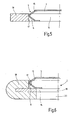
- Fig. 3 to 5 illustrate another embodiment in which the annular surface of the receptacle 5 is not formed by the edge of a groove, but by the radially inner edge 17 of a body 18 which is provided radially in the manner of a so-called Schulandstoppers on the seal carrier 2.
- the outer circumference of the sealing element 3 and / or the annular shape of the flank 17 have a different shape from the circular shape, so that the sealing element 3 is not fully clamped, but only locally in cooperation with the flank 17.
- the sectional view of Fig. 4 a peripheral portion at which no tension takes place while the sectional view accordingly Fig. 5 shows a section where the tension takes place.
- Fig. 6 shows a seal carrier 2 in the form of a multilayer board, wherein the actual receptacle 6 forming layer 19 and an adjoining layer 20 are provided, the latter being folded around with an outer edge surface around the edge of the layer 19 and wherein the folded part of the body 18th that forms at this Embodiment serves as a stopper whose inner edge 17 forms the annular surface for the bracing of the sealing element 13.
Landscapes
- Engineering & Computer Science (AREA)
- General Engineering & Computer Science (AREA)
- Mechanical Engineering (AREA)
- Chemical & Material Sciences (AREA)
- Combustion & Propulsion (AREA)
- Gasket Seals (AREA)
Abstract
Description
- Die Erfindung betrifft ein Dichtungssystem, insbesondere für Anschlußverbindungen an Strömungswegen für Heißgase, wie Abgasströme von Verbrennungskraftmaschinen, mit einem Dichtungsträger und einem Dichtelement, das eine zwischen Dichtflächen gelegene Dichtungsebene definiert und wobei der Dichtungsträger und das Dichtelement separate Bauteile darstellen, die mit Hilfe einer Verbindung verliersicher miteinander verbunden sind.
- Dichtungssysteme für Anschlußverbindungen in Heißgasbereichen, etwa bei Verbrennungskraftmaschinen, am Übergang zwischen dem Zylinderkopf und dem Abgaskrümmer oder am Krümmerausgang, am Turbolader oder Katalysator bedürfen eines vergleichsweise hohen, konstruktiven Aufwands, da an den genannten Stellen hohe thermische und mechanische Beanspruchungen auftreten.
- Als Dichtelemente eignen sich metallische Dichtungen aus hitzebeständigen Legierungen, die an Dichtungsträgern vormontiert werden können. Die Vormontage der Dichtelemente erfolgt in unterschiedlichster Weise verbunden mit einem zusätzlichen Herstellungsaufwand etwa für einen Formoder Kraftschluß zwischen dem Dichtungsträger und dem Dichtelement ermöglichenden Einrichtungen. Dies bedingt zudem einen Materialmehraufwand.
- Ausgehend von diesem Stand der Technik stellt sich die Erfindung die Aufgabe, ein Dichtungssystem für Anschlußverbindungen an Strömungswegen für Heißgase zu entwickeln, dessen Vormontage-Aufwand minimiert ist.
- Erfindungsgemäß ist diese Aufgabe durch ein Dichtungssystem gelöst, das die Merkmale des Patentanspruches 1 in seiner Gesamtheit aufweist.
- Danach besteht die wesentliche Besonderheit der Erfindung darin, dass die Verbindung zwischen dem Dichtungsträger und dem Dichtelement durch eine Aufnahme für das Dichtelement in den Dichtungsträger gebildet ist, welche ermöglicht, dass das Dichtelement in seinem in der Aufnahme eingelegten Zustand radial vorgespannt ist und somit kraftschlüssig gehalten ist.
- Bevorzugte Ausführungen ergeben sich aus den Unteransprüchen.
- Um einen möglichst geringen Herstellungsaufwand zu erreichen, ist das Dichtelement kreisförmig ausgebildet und die Aufnahme an dem Dichtungsträger beispielsweise als Nut oder Ringnut ausgebildet mit einer offenen Seite zu der Dichtungsebene hin orientiert. Die Nut oder Ringnut ist grundsätzlich derart dimensioniert, dass das kreisförmige Dichtelement zumindest teilweise radial darin eingelegt werden kann, wobei zumindest diejenige Flanke der Nut, die in Anlage zu einem Umfangsabschnitt des Dichtelementes gelangt, eine von der Kreisform abweichende Gestalt hat. Dies kann dem Grunde nach die äußere und/oder radial innere Flanke der betreffenden Nut sein. Insgesamt wird dadurch das Dichtelement radial leicht vorgespannt und kann so ohne die Notwendigkeit der Ausformung oder Anbringung von zusätzlichen Fixierhilfen an dem Dichtelement oder an dem Dichtungsträger verliersicher gehalten werden. Das Dichtelement ist gegen eine in eine Richtung quer zu der Dichtungsebene verlaufende Bewegung gesichert, kann aber für einen Dichtvorgang sich hinreichend anpassen.
- Insgesamt müssen aber die Außen- und Innenkonturverläufe von Dichtelement und Dichtungsträger derart unterschiedlich sein, dass es in benachbarten Teilbereichen zu einer klemmenden Anlage zwischen den genannten Bauteilen kommt. So besteht die Möglichkeit, bei einer bevorzugten Ausführungsform des Dichtungssystems eine demgemäß von der Kreisform abweichende Flanke der Aufnahmenut elliptisch oder polygonal auszubilden, wobei bevorzugt die radiale Abweichung von der Kreisform im Zehntel Millimeterbereich liegen kann. Alternativ oder zusätzlich kann auch das Dichtelement eine vergleichbare Ausgestaltung wie für das Dichtungssystem angegeben aufweisen und insbesondere bei einer Ausgestaltung als Vieleck für die Flanke der Nut sowie für die Außenkontur des Dichtelementes ist der Erhalt einer Art Verzahnungsstruktur möglich, die beim zahnenden Eingriff von Dichtelement und Dichtungsträger sicherstellt, dass radiale Relativbewegungen vermieden sind.
- Als Dichtungsträger selbst kann sowohl ein Ringkörper fungieren als auch ein platinen- oder flanschartiges Bauteil mit zumindest einer Durchgangsöffnung, um die die Nut mit ihrer vorzugsweise senkrecht zu der Dichtungsebene offenen Seite angeordnet sein kann. Solche platinenartigen Dichtungsträger eignen sich insbesondere für Anschlußverbindungen zwischen einem Abgaskrümmer und einem Zylinderkopfteil einer Verbrennungskraftmaschine.
- Bei besonders vorteilhaften Ausführungsformen ist das Dichtelement in der Art eines Formringes mit C-, U- oder V-förmigem Profilquerschnitt ausgebildet. Vorzugsweise ist ferner vorgesehen, dass ein derart aufgebauter Formring relativ zum Dichtungsträger und zum Strömungsweg der Heißgase in solcher Lageanordnung vorgesehen ist, dass die Profilform des Formringes radial nach innen in Richtung der Durchgangsöffnung geöffnet ist.
- Bei einer dahingehenden Lageorientierung gestaltet sich nicht nur die Verbindung zwischen Formring und Dichtungsträger am Sitz desselben konstruktiv besonders einfach, sondern aufgrund der zum Strömungsweg der Heißgase hin offenen Profilform ergeben sich auch besonders gute Verhältnisse hinsichtlich der Abdichtwirkung, weil der Formring vom Profilinneren her im Betrieb druckbeaufschlagt ist, was am Formring insbesondere im Bereich seiner Profilflanken aufweitend und dichtkrafterhöhend wirkt.
- Anstelle einer durch die Flanke einer Ringnut gebildeten Ringfläche der Aufnahme kann bei alternativen Ausführungsbeispielen die Ringfläche durch eine radial innen liegende Flanke eines am Dichtungsträger radial vorstehenden Körpers gebildet sein. Dabei kann die Anordnung so getroffen sein, dass der Körper ein einstückiges Bestandteil des Dichtungsträgers ist. Bei einem flachen-, platinen- oder flanschartigen Dichtungsträger kann dieser auch mehrlagig ausgebildet sein, wobei der die Ringfläche bildende Körper durch eine die Durchgangsöffnung des Dichtungsträgers umgebende Randfläche einer der Lagen gebildet ist.
- Nachstehend ist die Erfindung anhand von in der Zeichnung dargestellten Ausführungsbeispielen im Einzelnen erläutert. Es zeigen in prinzipieller und nicht maßstäblicher Darstellung die
- Fig. 1
- eine Draufsicht auf ein Dichtungssystem mit einem flanschartigen Dichtungsträger;
- Fig.2
- einen teilweisen Längsschnitt entlang der Linie II-II in
Fig. 1 ; - Fig. 3
- eine der
Fig. 1 ähnliche Draufsicht eines abgewandelten Ausführungsbeispieles; - Fig. 4
- einen teilweisen Längsschnitt entlang der Linie IV-IV in
Fig. 3 ; - Fig. 5
- einen teilweisen Längsschnitt entlang der Linie V-V in
Fig. 3 und - Fig. 6
- einen der
Fig. 2 ähnlichen, teilweisen Längsschnitt eines wei- ter abgewandelten Ausführungsbeispieles mit einem mehrla- gigen Dichtungsträger. - In
Fig. 1 ist in einer Draufsicht schematisch ein Dichtungssystem 1 für eine Abgasanlage einer Verbrennungskraftmaschine gezeigt. Das Dichtungssystem 1 besteht exemplarisch aus einem dreieckförmigen, flanschartigen Dichtungsträger 2, der eine Durchgangsöffnung 14 für Abgase aufweist. Der Dichtungsträger 2 dient mit einer als Ringnut 10 um die Durchgangsöffnung 14 herum gebildeten Aufnahme 6 zum Aufnehmen und Halten eines als Formring 15 gebildeten Dichtelementes 3. - Wie die
Fig. 2 in einem teilweisen Längsschnitt II - II inFig.1 durch das Dichtungssystem 1 zeigt, ist die Ringnut 10 als U-förmige Nut 7 mit einer radial äußeren Flanke 12 und einer radial inneren Flanke 13, die in Strömungsrichtung der Abgase ausgerichtet sind, gebildet. Der vorzugsweise als einteiliger Profilkörper ausgebildete metallische Formring 15 liegt axial etwa zur Hälfte in der Nut 7 und definiert eine Dichtungsebene 4 senkrecht zur Strömungsrichtung der Abgase. Die Nut 7 weist eine Flanke 8 auf, die radial innenliegend ist, deren Umfangsgestalt von der Kreisform geringfügig abweicht und in dem Ausführungsbeispiel bevorzugt elliptisch gewählt ist. Mit einen Umfangsabschnitt 9 liegt das Dichtelement 3 unter Bildung einer in axialer Richtung kraftschlüssigen Verbindung 5 an. Auf diese Weise ist durch eine einfache konstruktive Maßnahme ohne zusätzliche Befestigungsmittel eine einfache Vormontage des Dichtungssystems 1 ermöglicht, bei der das Dichtelement 3 in eine Stirnseite 11 des Dichtungsträgers 2 derart eingesetzt werden kann, dass das Dichtelement 3 zumindest gegen eine in eine Richtung quer zu der Dichtungsebene 4 verlaufende Bewegung gesichert ist und dennoch für einen Dichtvorgang bewegbar an dem Dichtungsträger 2 verbleibt. - Sofern auf den flanschartigen Dichtungsträger 2 ein nicht näher dargestelltes Deckelteil verbracht wird, wird in Blickrichtung auf die
Fig. 2 gesehen auf die obere Flanke des V-förmigen Dichtelementes 3 eine Preßkraft ausgeübt und der federelastisch nachgiebige Formring mit seinem äußerst linken Scheitel- oder Umlenkbereich nach links bezogen auf die Querschnittsdarstellung so lange in die Nut 7 verdrängt, bis gegebenenfalls der dahingehende Umlenkbereich an der äußeren Flanke 12 des Dichtungsträgers 2 für den Erhalt einer weiteren Abdichtebene unter Vorspannung anstößt. - Die
Fig. 3 bis 5 verdeutlichen ein weiteres Ausführungsbeispiel, bei dem die Ringfläche der Aufnahme 5 nicht durch die Flanke einer Nut, sondern durch die radial innen liegende Flanke 17 eines Körpers 18 gebildet ist, der in der Art eines sogenannten Hinterlandstoppers am Dichtungsträger 2 radial vorstehend vorgesehen ist. Wiederum haben der Außenumfang des Dichtelementes 3 und/oder die Ringform der Flanke 17 eine von der Kreisform abweichende Gestalt, so dass das Dichtelement 3 nicht vollumfänglich, sondern lediglich örtlich in Zusammenwirkung mit der Flanke 17 verspannt wird. Dementsprechend zeigt die Schnittdarstellung vonFig. 4 einen Umfangsabschnitt, an dem keine Verspannung stattfindet, während die Schnittdarstellung entsprechendFig. 5 einen Abschnitt zeigt, an dem die Verspannung stattfindet. - Das weitere Ausführungsbeispiel von
Fig. 6 zeigt einen Dichtungsträger 2 in Form einer mehrlagigen Platine, wobei eine die eigentliche Aufnahme 6 bildenden Lage 19 und eine daran anliegende Lage 20 vorgesehen sind, wobei letztere mit einer äußeren Randfläche um den Rand der Lage 19 umgelegt ist und wobei der umgelegte Teil den Körper 18 bildet, der bei diesem Ausführungsbeispiel als Stopper dient, dessen innere Flanke 17 die Ringfläche für das Verspannen des Dichtelementes 13 bildet.
Claims (14)
- Dichtungssystem, insbesondere für Anschlußverbindungen an Strömungswegen für Heißgase, wie Abgasströme von Verbrennungskraftmaschinen, mit einem Dichtungsträger (2) und einem Dichtelement (3), das eine zwischen Dichtflächen gelegene Dichtungsebene (4) definiert und wobei der Dichtungsträger (2) und das Dichtelement (3) separate Bauteile darstellen, die mit Hilfe einer Verbindung (5) verliersicher miteinander verbunden sind, dadurch gekennzeichnet, dass die Verbindung (5) durch eine Aufnahme (6) für das Dichtelement (3) in dem Dichtungsträger (2) gebildet ist, welche das Dichtelement (3) in seinem in die Aufnahme (6) eingelegten Zustand radial verspannt.
- Dichtungssystem nach Anspruch 1, dadurch gekennzeichnet, dass die Aufnahme (6) durch eine Ringfläche (12, 13, 17) gebildet ist.
- Dichtungssystem nach Anspruch 2, dadurch gekennzeichnet, dass die Ringfläche (12, 13, 17) und/oder das Dichtelement (3) eine Kreisform oder eine von der Kreisform derart abweichende Außenkontur haben, dass die genannten Bauteile gegeneinander verspannt sind.
- Dichtungssystem nach Anspruch 1 oder 2, dadurch gekennzeichnet, dass die Ringfläche durch eine Flanke (12, 13) einer U-förmigen Ringnut (10) gebildet ist, die an einer Stirnseite (11) des Dichtungsträgers (2) eingeformt ist und mit ihrer einen Seite zur Dichtungsebene (4) hin offen ist.
- Dichtungssystem nach Anspruch 4, dadurch gekennzeichnet, dass das Dichtelement (3) durch seine Anlage an einer radial äußeren Flanke (12) der Nut (7) radial vorgespannt ist.
- Dichtungssystem nach Anspruch 4, dadurch gekennzeichnet, dass das Dichtelement (3) durch seine Anlage an einer radial inneren Flanke (13) der Nut (7) radial vorgespannt ist.
- Dichtungssystem nach Anspruch 5 oder 6, dadurch gekennzeichnet, dass die radial äußere Flanke (12) und/oder die radial innere Flanke (13) der Nut (7) elliptisch geformt ist.
- Dichtungssystem nach Anspruch 5 oder 6, dadurch gekennzeichnet, dass die radial äußere Flanke (12) und/oder die radial innere Flanke (13) der Nut (7) polygonale Gestalt hat.
- Dichtungssystem nach einem der Ansprüche 4 bis 8, dadurch gekennzeichnet, dass der Dichtungsträger (2) ein flaches, platinen- oder flanschartiges Bauteil mit zumindest einer Durchgangsöffnung (14) ist, um die die Nut (7) mit ihrer in senkrechter Richtung zu der Dichtungsebene (4) hin offenen Seite angeordnet ist.
- Dichtungssystem nach Anspruch 2 oder 3, dadurch gekennzeichnet, dass die Ringfläche durch eine radial innenliegende Flanke (17) eines am Dichtungsträger (2) radial vorstehenden Körpers (18) gebildet ist.
- Dichtungssystem nach Anspruch 10, dadurch gekennzeichnet, dass der Dichtungsträger (2) ein flaches- platinen- oder flanschartiges mehrlagiges Bauteil mit zumindest einer Durchgangsöffnung (14) ist, wobei der die Ringfläche (17) bildende Körper (18) durch eine Durchgangsöffnung (14) umgebende Randfläche einer der Lagen (20) gebildet ist.
- Dichtungssystem nach einem der Ansprüche 1 bis 11, dadurch gekennzeichnet, dass der Außenumfang des Dichtelementes (3) eine von der Kreisform abweichende Kontur hat, insbesondere elliptisch geformt ist oder eine polygonale Gestalt, insbesondere in der Art einer Verzahnung hat.
- Dichtungssystem nach einem der Ansprüche 1 bis 12, dadurch gekennzeichnet, dass das Dichtelement (3) ein Formring (15) mit vorzugsweise C-, U- oder V-förmigem Profilquerschnitt ist.
- Dichtungssystem nach Anspruch 13, dadurch gekennzeichnet, dass der Formring (15) mit radial nach innen offener Profilform ausgebildet ist und aus federelastisch nachgiebigen Materialien besteht, wie beispielsweise Federstahl.
Applications Claiming Priority (1)
| Application Number | Priority Date | Filing Date | Title |
|---|---|---|---|
| DE200910042081 DE102009042081A1 (de) | 2009-09-17 | 2009-09-17 | Dichtungssystem |
Publications (2)
| Publication Number | Publication Date |
|---|---|
| EP2299148A1 true EP2299148A1 (de) | 2011-03-23 |
| EP2299148B1 EP2299148B1 (de) | 2012-06-13 |
Family
ID=43384637
Family Applications (1)
| Application Number | Title | Priority Date | Filing Date |
|---|---|---|---|
| EP20100007832 Not-in-force EP2299148B1 (de) | 2009-09-17 | 2010-07-28 | Dichtungssystem |
Country Status (3)
| Country | Link |
|---|---|
| EP (1) | EP2299148B1 (de) |
| CA (1) | CA2714356C (de) |
| DE (1) | DE102009042081A1 (de) |
Citations (2)
| Publication number | Priority date | Publication date | Assignee | Title |
|---|---|---|---|---|
| US20080073859A1 (en) * | 2006-09-27 | 2008-03-27 | Wilhelm Kullen | Sealing arrangement |
| WO2008037422A1 (de) * | 2006-09-27 | 2008-04-03 | Elringklinger Ag | Dichtungssystem, insbesondere für anschlussverbindungen an strömungswegen für heissgase |
-
2009
- 2009-09-17 DE DE200910042081 patent/DE102009042081A1/de not_active Ceased
-
2010
- 2010-07-28 EP EP20100007832 patent/EP2299148B1/de not_active Not-in-force
- 2010-09-07 CA CA2714356A patent/CA2714356C/en not_active Expired - Fee Related
Patent Citations (2)
| Publication number | Priority date | Publication date | Assignee | Title |
|---|---|---|---|---|
| US20080073859A1 (en) * | 2006-09-27 | 2008-03-27 | Wilhelm Kullen | Sealing arrangement |
| WO2008037422A1 (de) * | 2006-09-27 | 2008-04-03 | Elringklinger Ag | Dichtungssystem, insbesondere für anschlussverbindungen an strömungswegen für heissgase |
Also Published As
| Publication number | Publication date |
|---|---|
| DE102009042081A1 (de) | 2011-08-25 |
| CA2714356A1 (en) | 2011-03-17 |
| EP2299148B1 (de) | 2012-06-13 |
| CA2714356C (en) | 2017-01-03 |
Similar Documents
| Publication | Publication Date | Title |
|---|---|---|
| DE102010026853B4 (de) | Steuerventil zur Steuerung von Druckmittelströmen eines Nockenwellenverstellers | |
| DE19904299C1 (de) | Rastbeschlag für einen Fahrzeugsitz | |
| AT510857B1 (de) | Flüssigkeitsgekühlte brennkraftmaschine | |
| EP2845636B1 (de) | Filterelement und Verfahren zur Herstellung eines Filterelements | |
| EP2282825B1 (de) | Filtersystem | |
| EP1429058B1 (de) | Flachdichtung, insbesondere Abgaskrümmerdichtung | |
| DE2412567A1 (de) | Katalytischer abgasentgifter | |
| DE4343658A1 (de) | Gleitverbindungsvorrichtung zwischen zwei Teilen, die starken mechanischen und thermischen Belastungen unterliegen | |
| EP2066932A1 (de) | Dichtungssystem, insbesondere für anschlussverbindungen an strömungswegen für heissgase | |
| DE202011109832U1 (de) | Betätigungseinrichtung für ein Abgasstrom-Steuerelement eines Abgasturboladers | |
| EP3430250B1 (de) | Federelement für eine wastegate-klappe eines turboladers und ventilvorrichtung für einen turbolader | |
| EP2809973B1 (de) | Metallische flachdichtung | |
| EP2807350B1 (de) | Dichtung für eine einrichtung zum nachbehandeln von abgasen einer brennkraftmaschine | |
| DE102012107539A1 (de) | Metallische Flachdichtung und Verfahren zu ihrer Herstellung | |
| EP1769143B1 (de) | Abgasreinigungsvorrichtung für kraftfahrzeuge | |
| EP2446127B1 (de) | Dichteinheit | |
| WO2014173591A1 (de) | Flachdichtung | |
| EP2299148B1 (de) | Dichtungssystem | |
| EP1573240B1 (de) | Ventil | |
| DE202023105489U1 (de) | Ventilkäfig für ein Stellventil mit elastischem Bereich | |
| DE19523825A1 (de) | Metallische Flachdichtung | |
| WO2018002212A1 (de) | Flachdichtung sowie getriebesteuervorrichtung mit einer derartigen flachdichtung sowie verfahren zu deren herstellung | |
| EP3409909B1 (de) | Turbinenzwischengehäuse mit zentrierelement und distanzhalteelement | |
| DE10334044B4 (de) | Zylinderkopfdichtung | |
| EP3921534B1 (de) | Dichthülse und dichtanordnung mit dichthülse |
Legal Events
| Date | Code | Title | Description |
|---|---|---|---|
| PUAI | Public reference made under article 153(3) epc to a published international application that has entered the european phase |
Free format text: ORIGINAL CODE: 0009012 |
|
| AK | Designated contracting states |
Kind code of ref document: A1 Designated state(s): AL AT BE BG CH CY CZ DE DK EE ES FI FR GB GR HR HU IE IS IT LI LT LU LV MC MK MT NL NO PL PT RO SE SI SK SM TR |
|
| AX | Request for extension of the european patent |
Extension state: BA ME RS |
|
| 17P | Request for examination filed |
Effective date: 20110922 |
|
| GRAP | Despatch of communication of intention to grant a patent |
Free format text: ORIGINAL CODE: EPIDOSNIGR1 |
|
| GRAS | Grant fee paid |
Free format text: ORIGINAL CODE: EPIDOSNIGR3 |
|
| GRAA | (expected) grant |
Free format text: ORIGINAL CODE: 0009210 |
|
| AK | Designated contracting states |
Kind code of ref document: B1 Designated state(s): AL AT BE BG CH CY CZ DE DK EE ES FI FR GB GR HR HU IE IS IT LI LT LU LV MC MK MT NL NO PL PT RO SE SI SK SM TR |
|
| REG | Reference to a national code |
Ref country code: GB Ref legal event code: FG4D Free format text: NOT ENGLISH |
|
| REG | Reference to a national code |
Ref country code: AT Ref legal event code: REF Ref document number: 562147 Country of ref document: AT Kind code of ref document: T Effective date: 20120615 Ref country code: CH Ref legal event code: EP |
|
| REG | Reference to a national code |
Ref country code: IE Ref legal event code: FG4D Free format text: LANGUAGE OF EP DOCUMENT: GERMAN |
|
| REG | Reference to a national code |
Ref country code: DE Ref legal event code: R096 Ref document number: 502010000861 Country of ref document: DE Effective date: 20120809 |
|
| REG | Reference to a national code |
Ref country code: NL Ref legal event code: VDEP Effective date: 20120613 |
|
| PG25 | Lapsed in a contracting state [announced via postgrant information from national office to epo] |
Ref country code: LT Free format text: LAPSE BECAUSE OF FAILURE TO SUBMIT A TRANSLATION OF THE DESCRIPTION OR TO PAY THE FEE WITHIN THE PRESCRIBED TIME-LIMIT Effective date: 20120613 Ref country code: SE Free format text: LAPSE BECAUSE OF FAILURE TO SUBMIT A TRANSLATION OF THE DESCRIPTION OR TO PAY THE FEE WITHIN THE PRESCRIBED TIME-LIMIT Effective date: 20120613 Ref country code: NO Free format text: LAPSE BECAUSE OF FAILURE TO SUBMIT A TRANSLATION OF THE DESCRIPTION OR TO PAY THE FEE WITHIN THE PRESCRIBED TIME-LIMIT Effective date: 20120913 Ref country code: CY Free format text: LAPSE BECAUSE OF FAILURE TO SUBMIT A TRANSLATION OF THE DESCRIPTION OR TO PAY THE FEE WITHIN THE PRESCRIBED TIME-LIMIT Effective date: 20120613 Ref country code: FI Free format text: LAPSE BECAUSE OF FAILURE TO SUBMIT A TRANSLATION OF THE DESCRIPTION OR TO PAY THE FEE WITHIN THE PRESCRIBED TIME-LIMIT Effective date: 20120613 |
|
| REG | Reference to a national code |
Ref country code: LT Ref legal event code: MG4D Effective date: 20120613 |
|
| PG25 | Lapsed in a contracting state [announced via postgrant information from national office to epo] |
Ref country code: HR Free format text: LAPSE BECAUSE OF FAILURE TO SUBMIT A TRANSLATION OF THE DESCRIPTION OR TO PAY THE FEE WITHIN THE PRESCRIBED TIME-LIMIT Effective date: 20120613 Ref country code: LV Free format text: LAPSE BECAUSE OF FAILURE TO SUBMIT A TRANSLATION OF THE DESCRIPTION OR TO PAY THE FEE WITHIN THE PRESCRIBED TIME-LIMIT Effective date: 20120613 Ref country code: SI Free format text: LAPSE BECAUSE OF FAILURE TO SUBMIT A TRANSLATION OF THE DESCRIPTION OR TO PAY THE FEE WITHIN THE PRESCRIBED TIME-LIMIT Effective date: 20120613 Ref country code: GR Free format text: LAPSE BECAUSE OF FAILURE TO SUBMIT A TRANSLATION OF THE DESCRIPTION OR TO PAY THE FEE WITHIN THE PRESCRIBED TIME-LIMIT Effective date: 20120914 |
|
| BERE | Be: lapsed |
Owner name: ELRINGKLINGER A.G. Effective date: 20120731 |
|
| PG25 | Lapsed in a contracting state [announced via postgrant information from national office to epo] |
Ref country code: RO Free format text: LAPSE BECAUSE OF FAILURE TO SUBMIT A TRANSLATION OF THE DESCRIPTION OR TO PAY THE FEE WITHIN THE PRESCRIBED TIME-LIMIT Effective date: 20120613 Ref country code: CZ Free format text: LAPSE BECAUSE OF FAILURE TO SUBMIT A TRANSLATION OF THE DESCRIPTION OR TO PAY THE FEE WITHIN THE PRESCRIBED TIME-LIMIT Effective date: 20120613 Ref country code: SK Free format text: LAPSE BECAUSE OF FAILURE TO SUBMIT A TRANSLATION OF THE DESCRIPTION OR TO PAY THE FEE WITHIN THE PRESCRIBED TIME-LIMIT Effective date: 20120613 Ref country code: EE Free format text: LAPSE BECAUSE OF FAILURE TO SUBMIT A TRANSLATION OF THE DESCRIPTION OR TO PAY THE FEE WITHIN THE PRESCRIBED TIME-LIMIT Effective date: 20120613 Ref country code: IS Free format text: LAPSE BECAUSE OF FAILURE TO SUBMIT A TRANSLATION OF THE DESCRIPTION OR TO PAY THE FEE WITHIN THE PRESCRIBED TIME-LIMIT Effective date: 20121013 |
|
| PG25 | Lapsed in a contracting state [announced via postgrant information from national office to epo] |
Ref country code: PT Free format text: LAPSE BECAUSE OF FAILURE TO SUBMIT A TRANSLATION OF THE DESCRIPTION OR TO PAY THE FEE WITHIN THE PRESCRIBED TIME-LIMIT Effective date: 20121015 Ref country code: MC Free format text: LAPSE BECAUSE OF NON-PAYMENT OF DUE FEES Effective date: 20120731 Ref country code: PL Free format text: LAPSE BECAUSE OF FAILURE TO SUBMIT A TRANSLATION OF THE DESCRIPTION OR TO PAY THE FEE WITHIN THE PRESCRIBED TIME-LIMIT Effective date: 20120613 Ref country code: IT Free format text: LAPSE BECAUSE OF FAILURE TO SUBMIT A TRANSLATION OF THE DESCRIPTION OR TO PAY THE FEE WITHIN THE PRESCRIBED TIME-LIMIT Effective date: 20120613 Ref country code: MK Free format text: LAPSE BECAUSE OF FAILURE TO SUBMIT A TRANSLATION OF THE DESCRIPTION OR TO PAY THE FEE WITHIN THE PRESCRIBED TIME-LIMIT Effective date: 20120613 |
|
| PG25 | Lapsed in a contracting state [announced via postgrant information from national office to epo] |
Ref country code: NL Free format text: LAPSE BECAUSE OF FAILURE TO SUBMIT A TRANSLATION OF THE DESCRIPTION OR TO PAY THE FEE WITHIN THE PRESCRIBED TIME-LIMIT Effective date: 20120613 |
|
| PLBE | No opposition filed within time limit |
Free format text: ORIGINAL CODE: 0009261 |
|
| STAA | Information on the status of an ep patent application or granted ep patent |
Free format text: STATUS: NO OPPOSITION FILED WITHIN TIME LIMIT |
|
| PG25 | Lapsed in a contracting state [announced via postgrant information from national office to epo] |
Ref country code: DK Free format text: LAPSE BECAUSE OF FAILURE TO SUBMIT A TRANSLATION OF THE DESCRIPTION OR TO PAY THE FEE WITHIN THE PRESCRIBED TIME-LIMIT Effective date: 20120613 Ref country code: ES Free format text: LAPSE BECAUSE OF FAILURE TO SUBMIT A TRANSLATION OF THE DESCRIPTION OR TO PAY THE FEE WITHIN THE PRESCRIBED TIME-LIMIT Effective date: 20120924 |
|
| REG | Reference to a national code |
Ref country code: IE Ref legal event code: MM4A |
|
| 26N | No opposition filed |
Effective date: 20130314 |
|
| PG25 | Lapsed in a contracting state [announced via postgrant information from national office to epo] |
Ref country code: BE Free format text: LAPSE BECAUSE OF NON-PAYMENT OF DUE FEES Effective date: 20120731 |
|
| REG | Reference to a national code |
Ref country code: DE Ref legal event code: R097 Ref document number: 502010000861 Country of ref document: DE Effective date: 20130314 |
|
| PG25 | Lapsed in a contracting state [announced via postgrant information from national office to epo] |
Ref country code: MT Free format text: LAPSE BECAUSE OF FAILURE TO SUBMIT A TRANSLATION OF THE DESCRIPTION OR TO PAY THE FEE WITHIN THE PRESCRIBED TIME-LIMIT Effective date: 20120613 Ref country code: BG Free format text: LAPSE BECAUSE OF FAILURE TO SUBMIT A TRANSLATION OF THE DESCRIPTION OR TO PAY THE FEE WITHIN THE PRESCRIBED TIME-LIMIT Effective date: 20120913 Ref country code: IE Free format text: LAPSE BECAUSE OF NON-PAYMENT OF DUE FEES Effective date: 20120728 |
|
| PG25 | Lapsed in a contracting state [announced via postgrant information from national office to epo] |
Ref country code: AL Free format text: LAPSE BECAUSE OF FAILURE TO SUBMIT A TRANSLATION OF THE DESCRIPTION OR TO PAY THE FEE WITHIN THE PRESCRIBED TIME-LIMIT Effective date: 20120613 |
|
| PG25 | Lapsed in a contracting state [announced via postgrant information from national office to epo] |
Ref country code: TR Free format text: LAPSE BECAUSE OF FAILURE TO SUBMIT A TRANSLATION OF THE DESCRIPTION OR TO PAY THE FEE WITHIN THE PRESCRIBED TIME-LIMIT Effective date: 20120613 |
|
| PG25 | Lapsed in a contracting state [announced via postgrant information from national office to epo] |
Ref country code: LU Free format text: LAPSE BECAUSE OF NON-PAYMENT OF DUE FEES Effective date: 20120728 Ref country code: SM Free format text: LAPSE BECAUSE OF FAILURE TO SUBMIT A TRANSLATION OF THE DESCRIPTION OR TO PAY THE FEE WITHIN THE PRESCRIBED TIME-LIMIT Effective date: 20120613 |
|
| PG25 | Lapsed in a contracting state [announced via postgrant information from national office to epo] |
Ref country code: HU Free format text: LAPSE BECAUSE OF FAILURE TO SUBMIT A TRANSLATION OF THE DESCRIPTION OR TO PAY THE FEE WITHIN THE PRESCRIBED TIME-LIMIT Effective date: 20100728 |
|
| REG | Reference to a national code |
Ref country code: CH Ref legal event code: PL |
|
| GBPC | Gb: european patent ceased through non-payment of renewal fee |
Effective date: 20140728 |
|
| PG25 | Lapsed in a contracting state [announced via postgrant information from national office to epo] |
Ref country code: CH Free format text: LAPSE BECAUSE OF NON-PAYMENT OF DUE FEES Effective date: 20140731 Ref country code: LI Free format text: LAPSE BECAUSE OF NON-PAYMENT OF DUE FEES Effective date: 20140731 |
|
| PG25 | Lapsed in a contracting state [announced via postgrant information from national office to epo] |
Ref country code: GB Free format text: LAPSE BECAUSE OF NON-PAYMENT OF DUE FEES Effective date: 20140728 |
|
| REG | Reference to a national code |
Ref country code: DE Ref legal event code: R082 Ref document number: 502010000861 Country of ref document: DE Representative=s name: HOEGER, STELLRECHT & PARTNER PATENTANWAELTE MB, DE |
|
| REG | Reference to a national code |
Ref country code: FR Ref legal event code: PLFP Year of fee payment: 7 |
|
| REG | Reference to a national code |
Ref country code: AT Ref legal event code: MM01 Ref document number: 562147 Country of ref document: AT Kind code of ref document: T Effective date: 20150728 |
|
| PG25 | Lapsed in a contracting state [announced via postgrant information from national office to epo] |
Ref country code: AT Free format text: LAPSE BECAUSE OF NON-PAYMENT OF DUE FEES Effective date: 20150728 |
|
| REG | Reference to a national code |
Ref country code: FR Ref legal event code: PLFP Year of fee payment: 8 |
|
| REG | Reference to a national code |
Ref country code: FR Ref legal event code: PLFP Year of fee payment: 9 |
|
| REG | Reference to a national code |
Ref country code: DE Ref legal event code: R082 Ref document number: 502010000861 Country of ref document: DE Representative=s name: HOEGER, STELLRECHT & PARTNER PATENTANWAELTE MB, DE |
|
| P01 | Opt-out of the competence of the unified patent court (upc) registered |
Effective date: 20230512 |
|
| PGFP | Annual fee paid to national office [announced via postgrant information from national office to epo] |
Ref country code: DE Payment date: 20240719 Year of fee payment: 15 |
|
| PGFP | Annual fee paid to national office [announced via postgrant information from national office to epo] |
Ref country code: FR Payment date: 20240717 Year of fee payment: 15 |
|
| REG | Reference to a national code |
Ref country code: DE Ref legal event code: R119 Ref document number: 502010000861 Country of ref document: DE |
|
| PG25 | Lapsed in a contracting state [announced via postgrant information from national office to epo] |
Ref country code: DE Free format text: LAPSE BECAUSE OF NON-PAYMENT OF DUE FEES Effective date: 20260203 |
|
| PG25 | Lapsed in a contracting state [announced via postgrant information from national office to epo] |
Ref country code: FR Free format text: LAPSE BECAUSE OF NON-PAYMENT OF DUE FEES Effective date: 20250731 |