EP2298652B1 - Behälter und Verfahren zur Herstellung von Behältern - Google Patents
Behälter und Verfahren zur Herstellung von Behältern Download PDFInfo
- Publication number
- EP2298652B1 EP2298652B1 EP10191483A EP10191483A EP2298652B1 EP 2298652 B1 EP2298652 B1 EP 2298652B1 EP 10191483 A EP10191483 A EP 10191483A EP 10191483 A EP10191483 A EP 10191483A EP 2298652 B1 EP2298652 B1 EP 2298652B1
- Authority
- EP
- European Patent Office
- Prior art keywords
- separation line
- intended separation
- intended
- container
- wall
- Prior art date
- Legal status (The legal status is an assumption and is not a legal conclusion. Google has not performed a legal analysis and makes no representation as to the accuracy of the status listed.)
- Expired - Lifetime
Links
Images


Classifications
-
- B—PERFORMING OPERATIONS; TRANSPORTING
- B65—CONVEYING; PACKING; STORING; HANDLING THIN OR FILAMENTARY MATERIAL
- B65B—MACHINES, APPARATUS OR DEVICES FOR, OR METHODS OF, PACKAGING ARTICLES OR MATERIALS; UNPACKING
- B65B61/00—Auxiliary devices, not otherwise provided for, for operating on sheets, blanks, webs, binding material, containers or packages
- B65B61/18—Auxiliary devices, not otherwise provided for, for operating on sheets, blanks, webs, binding material, containers or packages for making package-opening or unpacking elements
-
- B—PERFORMING OPERATIONS; TRANSPORTING
- B65—CONVEYING; PACKING; STORING; HANDLING THIN OR FILAMENTARY MATERIAL
- B65B—MACHINES, APPARATUS OR DEVICES FOR, OR METHODS OF, PACKAGING ARTICLES OR MATERIALS; UNPACKING
- B65B9/00—Enclosing successive articles, or quantities of material, e.g. liquids or semiliquids, in flat, folded, or tubular webs of flexible sheet material; Subdividing filled flexible tubes to form packages
- B65B9/02—Enclosing successive articles, or quantities of material between opposed webs
- B65B9/04—Enclosing successive articles, or quantities of material between opposed webs one or both webs being formed with pockets for the reception of the articles, or of the quantities of material
-
- B—PERFORMING OPERATIONS; TRANSPORTING
- B65—CONVEYING; PACKING; STORING; HANDLING THIN OR FILAMENTARY MATERIAL
- B65D—CONTAINERS FOR STORAGE OR TRANSPORT OF ARTICLES OR MATERIALS, e.g. BAGS, BARRELS, BOTTLES, BOXES, CANS, CARTONS, CRATES, DRUMS, JARS, TANKS, HOPPERS, FORWARDING CONTAINERS; ACCESSORIES, CLOSURES, OR FITTINGS THEREFOR; PACKAGING ELEMENTS; PACKAGES
- B65D75/00—Packages comprising articles or materials partially or wholly enclosed in strips, sheets, blanks, tubes or webs of flexible sheet material, e.g. in folded wrappers
- B65D75/52—Details
- B65D75/58—Opening or contents-removing devices added or incorporated during package manufacture
- B65D75/5827—Tear-lines provided in a wall portion
- B65D75/5833—Tear-lines provided in a wall portion for tearing out a portion of the wall
-
- B—PERFORMING OPERATIONS; TRANSPORTING
- B65—CONVEYING; PACKING; STORING; HANDLING THIN OR FILAMENTARY MATERIAL
- B65B—MACHINES, APPARATUS OR DEVICES FOR, OR METHODS OF, PACKAGING ARTICLES OR MATERIALS; UNPACKING
- B65B61/00—Auxiliary devices, not otherwise provided for, for operating on sheets, blanks, webs, binding material, containers or packages
- B65B61/02—Auxiliary devices, not otherwise provided for, for operating on sheets, blanks, webs, binding material, containers or packages for perforating, scoring, slitting, or applying code or date marks on material prior to packaging
Definitions
- the invention relates to containers suitable for receiving products.
- the invention further relates to a method for producing containers.
- Containers are known that are obtained by thermoforming and that are delimited by a pair of facing walls, each one of which is made with a film of thermoformable material.
- Said walls define a containing body that is filled with a product, this containing body terminating in a neck having a transverse section with an extension that is noticeably less than the extension of a transverse section of the containing body, through which the product is delivered to and extracted from the containers.
- Said containers furthermore comprise a weakening line made in the container, at the above-mentioned neck.
- the weakening line comprises an incision obtained in a first wall of said pair of walls, and a further incision obtained in a second wall of said pair of walls.
- the zone of the first wall in which the incision is obtained, and the zone of the second wall in which the further incision is obtained are placed next to one another for a prevalent part of their extent, being spaced from each another only at the aforementioned neck.
- the weakening line mainly affects non-deformed zones of the first wall and of the second wall, namely zones that are far from those that define the containing body.
- the weakening line is shaped in such a way as to be transverse to the neck and to intersect the latter at an end thereof farther from the containing body.
- thermoformable material along the weakening line, in such a way as to make an opening in said neck.
- a stretch of the container is separated from a remaining part of the container comprising the containing body.
- the product contained in the containing body can be taken from the container by squeezing the walls and thus inducing the product to flow out through the opening made in the neck.
- a drawback of the aforementioned containers consists of the fact that they can be used only to contain flowing products.
- Products having a solid consistency could not in fact be extracted from the containers through an opening having a limited extent such as that defined by the transverse section of the aforementioned neck.
- the weakening line cannot be made at the containing body inasmuch as in this case the opening would be rather difficult, if not indeed impossible.
- the weakening line should in fact be made in deformed zones of the first wall and of the second wall that are both placed at a given distance from one another.
- the distance between said zones would prevent the containing body from having sufficient stiffness to be able to be broken with precision along the first incision and the second incision.
- cardboard containers are furthermore known, for example with a parallelepiped shape, containing solid flowable products, for example pastilles.
- Each of these containers is obtained starting from a single sheet of foldable material, for example cardboard, to which trimming machines give a preset shape comprising foldable strips.
- trimming machines obtain intended folding lines and weakening lines, the latter defining an opening zone of the future container.
- folding machines that act near the intended folding lines, progressively fold the sheet on itself so as to transform the latter into a three-dimensional structure. Once this structure has been made stable by gluing the adjacent strips, a containing body are available that can be filled through a residual opening with the solid flowing product.
- the residual opening is closed by further folding the strips and by gluing the latter to the body of the container.
- a user can break the wall of the container at the previously cut weakening lines, thus making an opening to dispense the product.
- containers are made for liquid food products, for example fruit juices or containers for solid film products, for example aluminium film products, or plastic material usable for wrapping foodstuffs and sold in the form of rolls.
- a drawback of the cardboard containers disclosed above consists of the fact that their manufacture involves the use of several machines, each one of which performs one of the phases disclosed above (trimming, punching, folding, gluing), and this makes these containers substantially complicated and costly to make.
- the roll-holder comprises a rod on which the roll can be inserted, and from which it can be unwound so as to enable the user to take stretches of card of the desired length from the roll.
- the roll-holder devices are made of stiff material, for example plastic material and are shaped in such a way as to be able to rest on a shelf or to be fixed to a wall.
- the roll-holding devices constitute a significant additional cost that the user has to incur to acquire the packages of kitchen-paper rolls.
- Dispensers are also known for packaged products such as packets of candies, chocolates or paper handkerchiefs, in which the products are stacked on top of each another.
- Such dispensers comprise dispensing means for dispensing the products contained inside them.
- the dispensing means is provided with a sliding drawer that is able to house a single product. By acting on the drawer, the user can pick up one product at a time from the dispenser.
- a drawback of the dispensers disclosed above is that they are not easy to manufacture inasmuch as each dispenser has to be fitted with a sliding drawer and with respective guides along which the drawer can run.
- Containers with an elongated shape are known, that are provided with a base wall suitable for being rested on a rest surface and with a body that extends from the base wall in a longitudinal direction for a preset height.
- a drawback of these containers is that their height cannot be chosen at will, but must remain below a limit value. In fact, if the height of the container is excessive, it is difficult to keep the container stably resting on the base wall, especially when the container is full of products and consequently has a relatively high centre of gravity.
- GB1213393 is directed to a sterilized surgical package comprising a polyethylene blister heat sealed to a paperboard panel having a tear strip formed by two parallel score lines cut half way through the panel from the exterior surface.
- GB2156303 discloses a packing containing a stack of sheets in the form of an envelope made from sheet material, which is folded around the stack and closed with flaps at each end face of the stack.
- the envelope is provided with at least two rows of perforations which between them define a tear strip to facilitate the opening thereof.
- Each of GB 1213393 and GB 2156303 discloses the container of the preamble of claim 1.
- An object of the invention is to improve the known containers. Another object is to obtain containers suitable for receiving any product, for example a fluid product that solidifies after being introduced into the containers, or a solid flowing product, or a film, or again a liquid product.
- a further object is to obtain a container that is provided with a dispensing opening of significant extent.
- a still further object is to obtain a system that enables a container to be produced that is particularly suitable for enabling a product having a solid consistency to be taken from it.
- Another object is to supply a container that is suitable for containing a solid flowing product, or a film product, which can be manufactured using a substantially simple procedure.
- a further object is to provide a container suitable for containing a solid flowing product, or film product, or a liquid product, which can be manufactured with a substantially reduced waste of time and, therefore, of money.
- a still further object is to supply a container for a solid product, or a film product, for example kitchen paper, that can be used to dispense the latter, thereby avoiding the use of a roll-holder.
- Another object is to provide a container for a plurality of products to be dispensed one at a time that is simple to manufacture and has an uncomplicated structure.
- Still another object is to obtain a container that can be stably rested on base wall means, even when the container is provided with a significant height.
- the first intended separation line and the second intended separation line define in the container a first portion, arranged on a part of said band, and a second portion arranged on an opposite part of said band in relation to said first portion.
- the container comprises further intended separation line means intersecting the first intended separation line and the second intended separation line.
- the portion of the wall means can remain partially bound to the container, thus acting as a "hatch" with which it is possible to reclose the container.
- the dispensing opening has a shape and dimensions such as to enable only one product at a time to be extracted from the container.
- the container according to this version can be used as a dispenser of products stacked one on top of each other, for example made-up products, such as packets of candies, chocolates or paper handkerchiefs. Through the dispensing opening, the consumer can in fact extract one product at a time. In this way, it is possible to avoid using dispensers provided with sliding drawers that are not easy to manufacture.
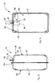
- a container 1 particularly suitable for being filled with a liquid, semisolid or solid product 6.
- the container 1 comprises a concave wall 2, thermosealed to a flat wall 3 along an edge zone 4.
- the concave wall 2 and the flat wall 3 cooperate to define a cavity 5 that receives the product 6.
- the concave wall 2 is made of a formable material, for example in plastic material, or paper, or aluminium, or cellulose-fibre-based material.
- the flat wall 3 is made of a flexible material, for example a film of aluminium or of plastic material, or of paper.
- the container 1 comprises instead of the flat wall 3, a further concave wall cooperating with the concave wall 2.
- the further concave wall may be made of formable material.
- the container 1 comprises a first intended separation line 7 and a second intended separation line 8 both intersecting the cavity 5 and obtained in an end zone 9 of the container 1.
- the first intended separation line 7 and the second intended separation line 8 each comprise a non-through incision through the concave wall 2, this incision in fact affecting only a surface zone of the film of formable material that defines the concave wall 2.
- Said incision may be made in a face of the concave wall 2 turned towards the outside of the container 1, such as not to damage any barrier layers associated with the face of the concave wall 2 turned to the inside of the container 1.
- the incisions can be made in a further face of the concave wall 2, opposite said face, turned to the inside of the container 1.
- the first intended separation line 7 and the second intended separation line 8 define in the concave wall 2 a band 10 interposed between the first intended separation line 7 and the second intended separation line 8 and provided with an appendage 11 protruding from the container 1 beyond the edge zone 4, in such a way as to define a grip part that facilitates the opening of the container 1.
- Opening of the container occurs, starting from a closed configuration, indicated by X in Figure 1 , in the following ways.
- a user may grasp the appendage 11 and remove it from the container 1 thereby making the concave wall 2 to break along the first intended separation line 7 and the second intended separation line 8, to take on a partially open configuration, indicated by Y in Figure 4 .
- the container 1 furthermore comprises "V"-shaped notches 30 made in the concave wall 2, near the appendage 11.
- the notches 30 enable easier opening of the container 1 inasmuch as, by acting as initiation promoting means, they induce the concave wall 2 to break along the first intended separation line 7 and the second intended separation line 8.
- first portion 12 containing a prevalent part 14 of the product 6 and a second portion 13, containing a remaining part 15 of the product 6.
- the second portion 13 is rotated in relation to the first portion 12 around a zone 16 of the flat wall 3 that acts as a plastic hinge, in such a way that the container takes on a completely open configuration, indicated by Z in Figure 5 .
- the remaining part 15, is therefore projected outside the cavity 5, being easily accessible to a user who can eat it, if necessary, even without having to handle it directly.
- said user can exert pressure on the concave wall 2, at a further end zone 17 thereof opposite the end zone 9, in such a way as to induce the product 6 to progressively emerge from the first portion 12.
- the product can therefore be consumed as it emerges from the cavity 5.
- said user can take the product 6 from the cavity 5 by manually acting on the remaining part 15.
- the container 1 is provided with an opening having a significant extent.
- said opening has an extent comparable to a transverse section of the cavity 5.
- the edge zone 4 may be sealed in a non-uniform manner.
- the concave wall 2 may be connected to the flat wall 3, at a stretch 18 of the edge zone 4 interposed between the first intended separation line 7 and the second intended separation line 8 and next to the appendage 11, by means of a seal that is weaker than the seal that is present on the remaining stretch 19 of the edge zone 4.
- the concave wall 2 may be connected to the flat wall 3, at the stretch 18, by means of a peelable seal.
- a container 1a made according to a variation, which comprises a further appendage 20 obtained in the flat wall 3 and formed in such a way as to face the appendage 11, when the container 1 is in the closed configuration X.
- the container 1a can be opened by acting in the same way as illustrated with reference to the container 1 disclosed above.
- the further appendage 20, with which the container 1a is provided, enables a facilitated opening to be obtained, inasmuch as an operator, by grasping the appendage 20, can firmly retain the container 1a with one hand whilst with the other hand he removes the band 10 from the container 1a, by acting on the appendage 11.
- the container is provided in the concave wall 2 with a first intended separation line 7, with a second intended separation line 8 and with an appendage 11, similarly to what has been previously disclosed.
- the container is furthermore provided, in the flat wall 3, with a further first intended separation line and with a further second intended separation line that both define a further band 32 that terminates in the further appendage 20.
- the first intended separation line 7, the second intended separation line 8, the further first intended separation line and the further second intended separation line are arranged in such a way that the band 10 and the further band 32 face each other when the container is in the closed configuration X.
- the container may comprise, in addition to the notches 30, further notches 31 made in the flat wall 3 near the further appendage 20.
- the further notches 31 induce the flat wall 3 to break along the further first intended separation line and the further second intended separation line.
- the container according to the invention - comprising a wall at consecutive zones of which a first intended separation line and a second intended separation line are made - can be obtained from injection-moulded plastic material.
- FIG. 8 there is schematically shown an apparatus for the production of containers, comprising an incision station 21 through which is made to advance a film 22 made of deformable material that is unwound from a reel 25.
- weakening means that makes in the film 22 a first incision and a second incision arranged mutually parallel to each another.
- the first incision and the second incision are intended to define a first intended separation line 7 and a second intended separation line 8 in containers obtained from said film.
- the first incision and the second incision may affect a face of the film 22 intended to define an external portion of the containers to be formed, or a further face of the film 22, opposite said face, intended to define an internal portion of the containers to be formed.
- a forming station 23 Downstream of the incision station 21 there is provided a forming station 23, in which the film 22, in which the first incision and the second incision were made, is thermoformed in such a way that half shells of containers, each one of which is provided with a concave wall 2, are defined therein.
- the forming station 23 is provided with moulds shaped in such a way as to enable to be obtained half shells of containers in which the concave wall 2 is transversely traversed by the first incision and by the second incision.
- a sealing station 24 Downstream of the forming station 23 there is provided a sealing station 24 in which a further film 26, unwound from a further reel 27, is sealed to the film 22 along an outline of the half shells made in the film 22, in such a way as to define intended edge zones 4 of the containers to be formed.
- the further film 26 is arranged to define flat walls 3 of the containers to be formed.
- the seal made in a stretch 18 of the edge zone 4, at which the film 22 has to be detached from the further film 26 during the opening of the container, is weaker than the seal that affects a remaining stretch 19 of the edge zone 4.
- a peelable seal can be made along the stretch 19.
- a blanking station 28 Downstream of the sealing station 24, there is provided a blanking station 28, in which the formed containers are separated from non-deformed portions of the first film 22 and of the second film 26.
- cutting means formed in such a way as to provide each container with an appendage 11 and a further appendage 20 arranged to act as handle means during the opening of the container.
- a filling station of the known type that is not shown, in which a product 6 is inserted inside the containers.
- containers 1a to be made of the type having an appendage 11 made in the film 22, a further appendage 20 made in the further film 26, and a first intended separation line 7 and a second intended separation line 8 made in the film 22.
- the apparatus may further comprise, upstream of the sealing station 24, a cutting station 29, in which in the further film 26 slots are made at the zones intended to face the parts of the film 22 in which the appendages 11 are made.
- a further incision station Upstream of the cutting station 29 there can be provided a further incision station, which is not shown, in which further weakness promoting means, similar to the above weakness promoting means, make in the further film 26 a further first incision and a further second incision arranged parallel to each other.
- This version of the apparatus enables a container to be obtained from a first portion 12 of which a second portion 13 can be completely separated.
- the apparatus comprises a further incision station, as disclosed above, the further forming station is interposed between the further incision station and the sealing station 24.
- the further film 26 is made of a deformable material.
- This version of the apparatus enables containers to be obtained having an appendage 10 associated with a concave wall 2, a further appendage 20 associated with a further concave wall, a first intended separation line 7 and a second intended separation line 8 made in the concave wall 2 and possibly a further first intended separation line and a further second intended separation line made in the further concave wall.
- the apparatus in the versions disclosed above, can also operate if a single film folded along a respective longitudinal axis so as to have facing strips rather than a pair of different films is made to advance through the operating stations.
- the apparatus further comprises injecting means for injecting plastic material.
- the injecting means is shaped in such a way as to form containers delimited by a continuous wall, in which a first intended separation line and a second intended separation line are obtained.
- the containers obtained by injection plastic material are provided with appendages arranged near said first intended separation line and said second intended separation line, which make the opening of the containers easier.
- a container 101 containing a flowing solid product 106, for example a sweet product in the form of pastilles.
- the container 101 comprises a first wall 102 and a second wall 103, sealed together, for example by thermosealing, along an edge zone 104. Between the first wall 102 and the second wall 103 there is defined a cavity 105, containing the solid flowing product 106.
- first concave portions 99 alternating with first convex portions 98.
- second concave portions 97 alternating with second convex portions 96.
- Both the first wall 102 and the second wall 103 are made of a formable material, for example plastic material.
- the first wall 102 comprises intended separation line means provided with a first intended separation line 107 and with a second intended separation line 108, that are parallel to each other and are obtained in consecutive zones of the first wall 102.
- the third intended separation line 94 and the fourth intended separation line 95 each intersect the first intended separation line 107 and the second intended separation line 108 in such a way as to define an opening portion 93 of the container 101 delimited by a closed contour 92.
- the closed contour 92 has a rectangular shape.
- the opening portion 93 is obtained in an end zone 109 of the first wall 102.
- the first intended separation line 107, the second intended separation line 108, the third intended separation line 94 and the fourth intended separation line 95 may comprise respective incisions obtained in the first wall 102.
- the incisions may be obtained on an external face 91 of the first wall 102, in such a way as not to damage any barrier layers associated with an internal face, which is not shown, of the first wall 102.
- the aforementioned incisions may be alternatively made in the internal face of the first wall 102.
- An appendage 111 for example rectangular in shape, is associated with the opening portion 93.
- the appendage 111 comprises a fixed end 90 that is fixed, for example by gluing or thermosealing, to an adjacent end of the opening portion 93.
- a free end 89 of the appendage 111, opposite the fixed end 90, is on the other hand available to be grasped by a user. In this way, the appendage 111 that protrudes from the container 101, can be used to facilitate the opening of the latter.
- a user can grasp the free end 89 of the appendage 111 and pull the latter towards the outside, in such a way as to induce the first wall 102 to break firstly along the fourth intended separation line 95, then along the first intended separation line 107 and the second intended separation line 108 and finally along the third intended separation line 94.
- This enables the user to remove the opening portion 93 from the external face 91 of the first wall 102, causing a dispensing opening, which is not shown, of rectangular shape, to appear. Through this opening, the user can dispense the solid flowing product 106 contained in the container 101.
- a container free of an appendage 111 there is provided a container free of an appendage 111.
- the user to open the container, can press from the outside on the opening portion 93 until the latter is detached from the surrounding external face 91 of the first wall 102 and is made to project it inside the cavity 105.
- FIGs 11 and 12 there is shown the container 101 in a version that is suitable for containing a liquid product, for example a fruit juice, in which the first wall 102 and the second wall 103 are respectively shaped like a first half shell 87 and a second half shell 88.
- the first half shell 87 and the second half shell 88 have a substantially rectangular plan-view shape, so as to give to the container 101 a substantially parallelepiped geometry.
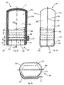
- FIG. 13 to 16 there is shown the container 101 in a version suitable for containing inside the cavity 105 a solid product in film, for example a roll 43 of kitchen paper.
- the first wall 102 is convex and comprises a shell 86 that has a substantially U-shaped transverse section that is oriented in such a way as to have its concavity turned towards the cavity 105.
- the first wall 102 extends in such a way as to almost completely peripherally envelop the roll 43 that is arranged in such a way as to be aligned on a longitudinal axis A of the container 101.
- the second wall 103 comprises a substantially rectangular-shaped flat surface 85 in such a way that the edge zone 104 can form a support flange of the container 101.
- the first intended separation line 107, the second intended separation line 108, the third intended separation line 94 and the fourth intended separation line 95 are obtained near a median region of the first wall 102.
- the first intended separation line 107 and the second intended separation line 108 extend parallel to the longitudinal axis A. In this way, the first intended separation line 107, the second intended separation line 108, the third intended separation line 94 and the fourth intended separation line 95 define a substantially strip-shaped opening portion 93.
- the first intended separation line 107 and the second intended separation line 108 extend along the entire length of the first wall 102, until they reach the edge zone 104 of the container 101.
- the opening portion 93 is delimited by a closed contour 92 with an irregular shape.
- the first intended separation line 107 develops in a rectilinearly whilst the second intended separation line 108 is shaped as a "saw tooth”.
- a user can grasp and pull towards himself the appendage 111, thus making the first wall 102 to break along the first intended separation line 107 and the second intended separation line 108.
- the user can then progressively remove, in a direction indicated by the arrow F1, the opening portion 93 of the first wall 102 and thus produce a dispensing opening 40 therein.
- the latter in view of the conformation of the closed contour 92 disclosed above, comprises a first rectilinear longitudinal margin 39 and a second serrated longitudinal margin 42.
- the user after grasping a free edge 44 of a film 45 of material making up the roll 43, can unwind the latter in a direction indicated by the further arrow F2 and extract the film 45 through the dispensing opening 40.
- the user can tear a portion of the film 45 along the second longitudinal margin 42.
- the edge zone 104 there can be obtained at least a through hole 41 usable for fixing the container 101 to a support wall.
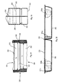
- Figures 18, 19 and 20 illustrate a version of the container 101 resting on a surface P and suitable for containing a solid product.
- the first wall 102 and the second wall 103 of the substantially cylinder-shaped container 101 are convex and respectively comprise a first semicylindrical shell 83 and a second semicylindrical shell 84.
- a base wall 54 having a substantially circular plan shape and which is divided by an end segment 46 of the edge zone 104 in a first region 47 and in a second region 48 that are substantially the same as one another. Both in the first region 47 and in the second region 48 projections 56 are obtained that are arranged to make the container 101 stably restable on the surface P.
- Each projection 56 is convex with convexity turned to the outside of the container 101 and has an approximately longitudinally sectioned ovoid shape arranged in such a way as to have an acute pole 57 turned to the end segment 46, and an obtuse pole 58 opposite that segment.
- the projections 56 are mutually staggered in the first region 47 and in the second region 48.
- the end segment 46 has a free margin 61 that is turned to the surface P when the container 101 rests on the latter.
- cuts 59 are obtained that alternate regularly with connection portions 60 that keep the first semicylindrical shell 83 and the second semicylindrical shell 84 joined at the base wall 54.
- the cuts 59 are made during forming of the container 101 and, once the first semicylindrical shell 83 and the second semicylindrical shell 84 have been sealed together, they enable an end segment 46 to be obtained that protrudes from the base wall 54 less than the projections 56. In this way, when the container 101 rests on the surface P, the free margin 61 cannot enter in contact with the latter. As a result, only the projections 56 are in contact with the surface P, enabling the container 101 to take on a stable vertical position.
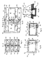
- a horizontal strip 62 of plastic material that is formable into a sheet there are made, for example by thermoforming, two parallel rows of first walls 102 and of second walls 103 respectively comprising first concave faces 64 and second concave faces 82.
- the projections 56 are further formed that are associated with both the first walls 102 and the second walls 103.
- the two aforementioned parallel rows are made in such a way that each first wall 102 is aligned on the opposite second wall 103, and the respective projections 56 face one another.
- the cuts 59 are further produced along a middle region of the strip 62 interposed between the two parallel rows of first walls 102 and second walls 104.
- first intended transverse separation line 207 and a second intended transverse separation line 208 that are parallel to one another and that orthogonally intersect a first longitudinal edge 67 and a second longitudinal edge 68 of the first wall 102.
- the first intended transverse separation line 207 and the second intended transverse separation line 208 are made in a zone of the first wall 103 near the projections 56, in such a way that the first intended transverse separation line 207 is interposed between the projections 56 and the second intended transverse separation line 208.
- the first intended transverse separation line 207 and the second intended transverse separation line 208 can be made in the form of incisions.
- a further intended separation line 69 is obtained near the second concave faces 82, at a preset distance from each second wall 103 and parallel to the latter.
- the further intended separation line 69 has a length 1 that is greater than a distance d running between the first intended transverse separation line 207 and the second intended transverse separation line 208. This enables the first intended transverse separation line 207 and the second intended transverse separation line 208 to be intersected by the further intended separation line 69 when the first wall 102 and the second wall 103 are sealed to one another.
- the further intended separation line 69 can be made in the form of an incision.
- the strip 62 is folded longitudinally in half at the cuts 59 so that the first concave face 64 of each first wall 102 faces the second concave face 82 of the opposite second wall 103.
- thermosealed strip 63 shown as a dotted area in Figures 23 and 24 ).
- thermosealing is interrupted at two zones, a first zone 76 and a second zone 77.
- the first zone 76 is comprised between a first longitudinal margin 72 of the container 101 and corresponding end portions of the first intended transverse separation line 207 and of the second intended transverse separation line 208, which are in turn intersected by the further intended longitudinal separation line 69.
- the second zone 77 is comprised between further end portions of the first intended transverse separation line 207 and of the second intended transverse separation line 208, which protrudes from a second longitudinal margin 73 of the container 101.
- the first zone 76 has a greater extent than the second zone 77.
- an opening portion 93 is consequently defined that is substantially shaped as a rectangle.
- the containers 101 are separated by partially removing the interposed portions of thermosealed strip 63, the residue of which constitutes the edge zone 104.
- thermosealed strip 63 is removed in such a way as to form an appendage 211 that substantially protrudes from the edge zone 104 and comprises a thermosealed peripheral portion 65 that partially surrounds the first zone 76.
- a further cut 80 and a pair of intended oblique separation lines 78 and 79 are made parallel to the second longitudinal margin 73 and near the second zone 77, and is of such a length as to intersect corresponding end portions of the first intended transverse separation line 207 and of the second intended transverse separation line 208.
- Each of the two intended oblique separation lines 78 and 79 originates at the boundary between the edge zone 104 and the appendage 211 and runs in a rectilinear manner to penetrate the first zone 76, in such a way as to intersect both the further intended longitudinal separation line 69 and the corresponding end portions of the first intended transverse separation line 207 and of the second intended transverse separation line 208.
- the appendage 211 is approximately shaped as a triangle and can be used to open the container 101.
- the appendage 211 remains fixed to the opening portion 93.
- the user By continuing to pull the appendage 211 towards himself, the user induces the first wall 102 to break along the first intended transverse separation line 207 and the second intended transverse separation line 208. In this way, the opening portion 93 is removed and a dispensing opening is defined in its place. Owing to the presence of the further cut 80, the user can completely remove the opening portion 93 from the container 101.
- the opening portion 93 remains bound to the container 101 after the latter has been opened. In this way, the dispensing opening may, if necessary, be reclosed by the user.
- a strip portion 62 having dimensions and shape approximately corresponding to those of the appendage 211, is removed from the strip region 62 in which the further intended separation line 69 should be obtained.
- the appendage 211 comprises a single layer of material making up the strip 62.
- a container 101 suitable for containing a solid product in film that comprises the first intended transverse separation line 207, the second intended transverse separation line 208, the further intended separation line 69 and the further cut 80 disclosed above.
- the container 101 shown in Figure 26 is made without the further cut 80. Consequently, the opening portion 93 remains bound to the container 101 and can be used to reclose the dispensing opening once the latter has been produced.
- Figures 27 to 29 show a container 301 comprising a first shell 383 and a second shell 384 joined together along an edge zone 304.
- the first shell 383 and the second shell 384 can be obtained by deforming a sheet material initially arranged in flat form, for example by thermoforming a film in thermoformable plastic material. Nevertheless, it is also possible to use other materials, for example cellulose-based materials or multilayered materials such as paper coupled with plastic and/or aluminium films.
- first shell 383 and the second shell 384 are joined together along the edge zone 304, for example by thermosealing or gluing.
- first shell 383 and the second shell 384 When the first shell 383 and the second shell 384 are joined together, they define in the container 301 a cavity 305 that is suitable for receiving objects of different types, for example stackable products 306 such as packets of candies, or chocolates, or still again paper handkerchiefs.
- stackable products 306 such as packets of candies, or chocolates, or still again paper handkerchiefs.
- the cavity 305 is delimited by a base wall 354 having a substantially flat shape, such as to be able to be operatively rested on a rest surface, that is not shown, and is defined by adjacent regions of the first shell 383 and of the second shell 384.
- the edge zone 304 may also extend in the base wall 354, in which case the edge zone 304 protrudes inside the cavity 305, so as not to protrude from the base wall 354 and to enable the latter to be stably rested on the rest surface.
- the edge zone 304 does not extend on the base wall 354 because the first shell 383 and the second shell 384 have been formed on a single sheet that was subsequently folded so as to place the first shell 383 and the second shell 384 in a position in which they face each another.
- the base wall 354 it is possible to define, instead of a portion of the edge zone 304, a folding line of the sheet material.
- lateral wall means comprising a first wall 302 and a second wall 303 that are obtained respectively in the first shell 383 and in the second shell 384.
- the lateral wall means is shaped substantially as a prism, the transverse section of which prism corresponds to the plan shape of the products 306.
- the lateral wall means extends around a longitudinal axis V of the container 301 that, in the example of the Figures 27 and 28 , is substantially perpendicular to the base wall 354 and is vertically positionable during use of the container 301.
- the first intended separation line 307 and the second intended separation line 308 are arranged at a reciprocal distance d1 that is slightly greater than a thickness S of the products 306, the thickness S being measured along the longitudinal axis V.
- the first intended separation line 307 is interposed between the base wall 354 and the second intended separation line 308 and is at a distance d2 from the base wall 354.
- the first intended separation line 307 and the second intended separation line 308 may comprise incisions that can be obtained on an external face of the first wall 302 or on an internal face of this wall.
- the first intended separation line 307 and the second intended separation line 308 define on the first wall 302 a band 310, arranged between the first intended separation line 307 and the second intended separation line 308.
- the band 310 is provided with an appendage 311 that protrudes outside the edge zone 304, in such a way as to act as grasp means for a user who wishes to act on the strip 310 to access the products 306.
- An opening is thus defined through which it is possible to extract the products 306 from the container 301.
- Said opening has dimensions and a shape such as to enable one product 306 at a time to be extracted.
- the height of the opening is the same as the reciprocal distance d1 between the first intended separation line 307 and the second intended separation line 308 and as such it is slightly greater than the thickness S of a product 306 but is less than the sum of the thicknesses S of two products 306 stacked on top of each another.
- the opening furthermore extends between two opposite regions of the edge zone 304 and as such has a width that is slightly greater than that of each product 306.
- the band 310 can remain attached to the container 301 along the joining zone 304. In this case, it is possible to reposition the band on the opening of the container 301 in such a way as to reclose this opening.
- the band 310 can be completely removed from the container 301, thanks to a third intended separation line arranged transversely to the first intended separation line 307 and to the second intended separation line 308 and intersecting these last two lines.
- the container 301 further comprises support means 320 arranged to support the products 306 near the opening defined by removing the band 310.
- the support means 320 shown in Figures 30 and 31 , may comprise an internally hollow spacing element 321 having the form of an upturned glass provided with a transverse wall 322 suitable for supporting a product 306 and longitudinal walls 323 that extend from the transverse wall 322 so as to protrude towards the base wall 354.
- the spacing element 321 has a plan shape corresponding to that of the container 301, so that the longitudinal walls 323 can engage in the first wall 302 and in the second wall 303 of the container 301 with very small or almost nonexistent gap.
- the longitudinal walls 323 of the spacing element 321 are delimited, on the opposite part in relation to the transverse wall 322, by an end region 324 that during use of the container 301 rests on the base wall 354, as shown in Figure 30 .
- the spacing element 321 is dimensioned in such a way that, when it is inserted inside the container 301 the transverse wall 322 is at a first distance d3 from the rest surface on which the base wall 354 rests.
- the first distance d3 is about the same as the distance d2 that separates the base wall 354 from the first intended separation line 307.
- the container 301 When the container 301, provided with the spacing element 321 and filled with a stack of products 306, is in a configuration in which the base wall 354 rests on a rest surface, the product 306 arranged at the lowest position of the stack is supported by the transverse wall 322 of the spacing element 321. As the first distance d3 is approximately the same as the distance d2, the product 306 arranged in the lowest position of the stack is at the opening that is definable by removing the band 310. It is thus possible, after removing the band 310, to extract the product 306 arranged in the lowest position of the stack from the opening thus defined. At this point, the products 306 contained in the container 301 descend by gravity inside the cavity 305, so that a new product 306 is arranged on the spacing element 321, this product being ready to be extracted from the container 301.
- the container 301 can thus easily be used as a dispenser to dispense a plurality of stacked products 306 one at a time.
- the distance d2 is slightly less than the first distance d3.
- the product 306 arranged at the bottom of the stack rests on the transverse wall 322 of the spacing element 321 just above the first intended separation line 307.
- This enables the product 306 to be extracted from the container 301 in an extremely easy manner, as the product 306 does not interfere with the first intended separation line 307.
- the reciprocal distance d1 between the first intended separation line 307 and the second intended separation line 308 is sufficiently greater than the thickness S of the product 306 so that the product 306 can arrange itself below the second intended separation line 308, extracting the product 306 from the container 301 is even easier because the product 306 does not even interfere with the second intended separation line 308.
- the spacing element 321 has a double function. On one hand, it enables the product 306 to be kept lower in the stack at a preset distance from the base wall 354, so that the product 306 is near the opening defined by removing the band 310. On the other hand, the spacing element 321 makes the container zone 301 next to the base wall 354 stiffer. In this way, the container 301 can remain resting on the rest surface in a very stable manner.
- the container 301 is also made more stable because the opening defined by removing the band 310 is arranged at a certain distance from the base wall 354.
- the portion of the first wall 302 defined between the base wall 354 and the first intended separation line 307 enables the container 301 to be made stiffer than if the first intended separation line 307 had been made immediately above the base wall 354.
- Figure 32 shows an alternative version of the support means 320, comprising an entirely hollow spacing element 421 provided with external longitudinal walls 325 and with internal walls 326.
- the external longitudinal walls 325 and the internal longitudinal walls 326 are joined together at a rim 327 that may for example have a rounded profile if viewed in cross-section.
- the rim 327 defines an annular support zone for supporting the products 306.
- the spacing element 421 comprises a stiffening wall 328 that extends from a lower region of the internal longitudinal walls 325 so as to rest on the base wall 354.
- a recess 329 is thus defined that is provided with a concavity that faces the products 306.
- the spacing element 421 is particularly suitable when inside the container 301 products 306 are received that may undergo expansion, for example increasing their dimensions in the direction of the longitudinal axis V. These expansions may be due to the release of gas by products 306 packaged inside the respective packages or to temperature variations of the products 306.
- the products 306 may partially expand inside the recess 329, which therefore enables the dimensions of the products 306 to be compensated for to a certain extent even when the container 301 is still full.
- the support means 320 comprises a spacing element 521 that instead of being internally hollow as in the examples in Figures 31 and 32 , comprises a full body suitable for resting on the base wall 354, and may be provided with a plan shape corresponding to that of the cavity 305.
- the spacing element 521 is rather heavy and operatively acts as a stabilizing means, i.e. as a sort of ballast that makes it impossible to stably rest the base wall 354 of the container 301 on a rest surface.
- the spacing element 521 in fact enables the centre of gravity of the container 301 to be kept in a relatively low position. As a result, the container easily remains in a vertical position even when it is full or when the user acts on it to extract the single products 306.
- the spacing elements 321 and 421 of the Figures 31 and 32 can act as stabilizing means if they are for example made with a material having a relatively high specific weight, for example metal. Alternatively, it is possible to place a weight inside the recess 329 of the spacing element 421 shown in Figure 32 or between the base wall 354 of the container 301 and the transverse wall 322 of the spacing element 321 shown in Figure 31 .
- the support means 320 is obtained by suitably shaping the side wall means of the container 301.
- a first part 330 arranged near the base wall 354, and a second part 331 operatively positioned above the first part 330 are definable.
- the first part 330 has a transverse dimension T1 that is less than a further transverse dimension T2 of the second part 331.
- a narrowing 332 that is shaped as a step on which can rest the product 306 arranged in the lowest position in the stack of products received in the cavity 305.
- the narrowing 332 is positioned near the band 310, so as to enable the products 306 to be easily extracted from the container 301.
- the support means 320 comprises an indentation 333, obtained on the first shell 383 and on the second shell 384 and projecting to the inside of the container 301.
- the indentation 333 defines inside the container 301 an annular rest zone for supporting the product 306 arranged in the lowest position in the stack of products 306 housed inside the cavity 305.
- the indentation 333 may extend in a continuous manner around the longitudinal axis V and transversely to it, or it can be replaced by a plurality of substantially punctiform zones projecting inside the container 301 and distributed in a uniform manner around the longitudinal axis V. In this case, the products 306 do not rest on a continuous zone but on a plurality of support points.
- the container 301 is delimited by a first wall 302 provided with a concavity sufficient to house the products 306 and with a substantially flat second wall 303.
- the container 301 may also house products with an irregular shape arranged in bulk in the cavity 305.
- the opening defined by removing the band 310 may have a shape and dimensions such as to enable more than one product at a time to be removed from the container 301.
- the opening obtained by removing the band 310 extends transversely over the entire first wall 302, i.e. between two opposite regions of the edge zone 304. In a version that is not shown, this opening may have smaller dimensions extending transversely only on a limited part of the first wall 302.
- the opening obtained by removing the band 310 is immediately above the base wall 354, i.e. the distance d2 is almost the same as the thickness of the base wall 354.
- a promotional product for example a leaflet or advertising coupon, or a product containing other information or a musical disc or video such as a compact disc or DVD, or a disc for an electronic game or a video game.
- the container 301 may be made of a material that is at least partially transparent, through which it is possible to see the number of products 306 that are still present in the cavity 305.
- Figures 36 and 37 show a container 401 that differs from the container 301 shown in Figures 27 to 29 inasmuch as it is provided with a dividing wall 334 extending inside the container 401 parallel to the longitudinal axis V.
- the dividing wall 334 defines inside the container 401 a first cavity 305a and a second cavity 305b separate from one another and suitable for receiving respective products.
- the first cavity 305a is defined between the first shell 383 and the dividing wall 334
- the second cavity 305b is defined between the second shell 384 and the dividing wall 334.
- the first cavity 305a may for example receive first products 306a and the second cavity 305b may receive second products 306b, different from the first products 306a.
- a first band 310a is associated that is defined between a respective first intended separation line 307a and a second intended separation line 308a, and is provided with a respective appendage 311a, similarly to what has been disclosed with reference to Figure 27 .
- Support means comprising a first spacing element 321a, made according to one of the versions disclosed with reference to Figures 31 to 35 enables the first products 306a to be supported near the first opening obtained by removing the first band 310a.
- a further first intended separation line 307b and a further second intended separation line 308b that are parallel to each other and define a second band 310b that can be removed by acting on a second appendage 311b.
- the second cavity 305b is furthermore provided with a second spacing element 321b made according to one of the shapes disclosed with reference to Figures 31 to 35 , arranged to support the second products 306b near a second opening defined by removing the second band 310b.
- the first band 310a and the second band 310b are obtained on opposite sides of the container 401.
- the container 401 when it is desired to access the first products 306a contained in the first cavity 305a, the container 401 is arranged in a first configuration in which the base wall 354 is in contact with a rest surface, in such a way that the first band 310a is near the rest surface. If on the other hand it is desired to access the second products 306b contained in the second cavity 305b, the container 401 is overturned to reach a second configuration in which a further base wall 454 opposite the base wall 354 is rested on the rest surface.
- first band 310a near the base wall 354 and the second band 310b near the further base wall 454 enables stiffness of the container 401 not to be excessively lessened, also when the first band 310a and the second band 310b are both removed to make both the first products 306a and the second products 306b accessible.
- first spacing element 321a and the first band 310a are arranged near the base wall 354, whereas the second spacing element 321b and the second band 310b are arranged near the further base wall 454. This enables easy access to the desired products, both in the first configuration and in the second configuration.
- the container 401 comprises two bands 310a and 310b, certain operations disclosed with reference to said Figures will have to be repeated both on the first shells 383 and on the second shells 384.
- a closing sheet 335 for example a film in thermosealable plastic material at the edge zone 304.
- the first shell 383 and the second shell 384 are then rotated in relation to each other around a folding line 336 in such a way that consecutive regions of the closing sheet 335, associated respectively with the first shell 383 and the second shell 384, face each other.
- a folding line 336 in such a way that consecutive regions of the closing sheet 335, associated respectively with the first shell 383 and the second shell 384, face each other.
- the dividing wall 334 is defined by two layers of closing sheet 335 arranged to be in contact with each other.
- a dividing wall formed by a single layer of the closing sheet having a face in contact with the first products 306a and a further face in contact with the second products 306b.
- the first cavity 305a and the second cavity 305b can be opened almost simultaneously if it is desired to access both the first products 306a and the second products 306b. If, on the other hand, it is desired to access the second products 306b only after the first products 306a have been consumed, the second band 310b is torn when the first cavity 305a is empty. This enable storage of the second products 306b to be improved, which can be kept in the second closed cavity 305b, preventing contact with the air, whilst the user consumes the first products 306a.
- containers provided with an arbitrary number of cavities.
- a container 501 inside which four cavities 405 are definable, arranged around the longitudinal axis of the container 501 and each extending between the base wall 354 and the further base wall 454.
- Each cavity 405 is separated from the adjacent cavities 305 by respective dividing walls 434.
- Each cavity 405 is provided with a respective band 410, defined between a first intended separation line 407 and a second intended separation line 408 that are parallel to each other. By removing a band 410, it is possible to access the products contained in the corresponding cavity 405.
- two adjacent cavities 405 are accessible by removing respective bands 410 arranged near the base wall 354, whereas the other two cavities 405 are accessible by removing further respective bands 410 arranged near the further base wall 454. This enables the container 501 to be kept sufficiently stiff even when all four bands 410 have been removed.
- the bands 410 can be alternatively obtained near the base wall 354 and the further base wall 454.
- a certain cavity 405 there is associated a band 410 arranged near the base wall 354, whereas the two adjacent cavities 405 are provided with bands 410 arranged near the further base wall 454.
- the container 501 can be manufactured in a similar manner to what has been disclosed with reference to Figure 38 , using a pair of first shells 383 and a pair of second shells 384 that are each closed by the closing sheet 335.
- the container 501 may be obtained by bringing up two containers that are similar to those disclosed with reference to Figures 27 to 29 , and are provided with at least a flat portion along which the two containers can be brought up and joined.
Landscapes
- Engineering & Computer Science (AREA)
- Mechanical Engineering (AREA)
- Packages (AREA)
- Transforming Light Signals Into Electric Signals (AREA)
- Peptides Or Proteins (AREA)
- Cartons (AREA)
- Supplying Of Containers To The Packaging Station (AREA)
Claims (12)
- Behälter mit Wandmitteln (2, 3; 102, 103; 302, 303), die ein Hohlraummittel (5; 105; 305; 405) definieren, das dazu geeignet ist, ein Produkt (6; 43; 106; 306; 306a, 306b) aufzunehmen, wobei der Behälter mit einem Plantrennlinienmittel (7, 8; 107, 108; 207, 208; 307, 308; 307a, 307b, 308a, 308b; 407, 408) versehen ist, das in den Wandmitteln (2, 3; 102, 103; 302, 303) aufgenommen ist, wobei das Plantrennlinienmittel (7, 8; 107, 108; 207, 208; 307, 308; 307a, 307b, 308a, 308b; 407, 408) eine erste Plantrennlinie (7; 107; 207; 307; 307a, 307; 407) und eine zweite Plantrennlinie (8; 108; 208; 308; 308a, 308b; 408) aufweist, wobei die erste Plantrennlinie (7; 107; 207; 307; 307a, 307b; 407) und die zweite Plantrennlinie (8; 108; 208; 308; 308a, 308b; 408) in aufeinanderfolgenden Zonen der Wandmittel (2, 3; 102, 103; 302, 303) angeordnet sind, wobei der Behälter des Weiteren ein weiteres Plantrennlinienmittel (69, 78, 79, 80) aufweist, das die erste Plantrennlinie (7; 107; 207, 208; 307; 307a, 307b; 407) und die zweite Plantrennlinie (8; 108; 208; 308; 308a, 308b; 408) schneidet, um während des Betriebs das Entfernen von einem Öffnungsabschnittsmittel (93) zu ermöglichen, das zwischen der ersten Plantrennlinie (7; 107; 207, 208; 307; 307a, 307b; 407) und der zweiten Plantrennlinie (8; 108; 208; 308; 308a, 308b; 408) definiert ist, dadurch gekennzeichnet, dass das weitere Plantrennlinienmittel (69, 78, 79, 80) ein erstes weiteres Plantrennlinienmittel (69) aufweist, das entsprechende Endabschnitte der ersten Plantrennlinie (7; 107; 207, 208; 307; 307a, 307b; 407) und der zweiten Plantrennlinie (8; 108; 208; 308; 308a, 308b; 408) schneidet, wobei das weitere erste Plantrennlinienmittel (69) dazu angeordnet ist, die Entfernung des Öffnungsabschnittsmittels (93) zu ermöglichen, wobei die Wandmittel (2, 3; 102, 103; 302, 303) ein erstes Wandmittel (2; 102; 302) und ein zweites Wandmittel (3; 103; 203) aufweisen, wobei das Plantrennlinienmittel (7, 8; 107, 108; 207, 208; 307, 308; 307a, 307b, 308a, 308b; 407, 408) in dem ersten Wandmittel (2; 102; 302) aufgenommen ist, wobei das erste weitere Plantrennlinienmittel (69) in dem zweiten Wandmittel (3; 103; 203) aufgenommen ist.
- Behälter nach Anspruch 1, wobei das weitere Plantrennlinienmittel (69, 78, 79, 80) ein zweites weiteres Plantrennlinienmittel (80) entgegengesetzt zu dem ersten weiteren Plantrennlinienmittel (69) und weitere entsprechende Endabschnitte der ersten Plantrennlinie (7; 107; 207, 208; 307; 307a, 307b; 407) und der zweiten Plantrennlinie (8; 108; 208; 308; 308a, 308b; 408) schneidend aufweist, wobei zweite weitere Plantrennlinienmittel (80) dazu angeordnet sind, während des Betriebs eine vollständige Entfernung des Öffnungsabschnittsmittels (93) zu ermöglichen.
- Behälter nach Anspruch 1 oder 2, wobei die Wandmittel entlang einer Umfangsverbindungszone (4; 104; 304; 404) miteinander verbunden sind, und wobei das erste weitere Plantrennlinienmittel (69) die entsprechenden Endabschnitte nahe einer ersten Unterbrechungszone (76) der Umfangsverbindungszone (4; 104; 304) schneidet.
- Behälter nach Anspruch 3, der des Weiteren ein Anhängsel (211) aufweist, das von der Umfangsverbindungszone (4; 104; 304) vorsteht, wobei das Anhängsel (211) einen wärmegedichteten Umfangsabschnitt (65) aufweist, der die erste Unterbrechungszone (76) teilweise umgibt.
- Behälter nach Anspruch 3 oder 4, wobei Anspruch 3 auf Anspruch 2 rückbezogen ist, wobei das zweite weitere Plantrennlinienmittel (80) die weiteren entsprechenden Endabschnitte nahe einer zweiten Unterbrechungszone (77) der Umfangsverbindungszone (4; 104; 304) schneidet.
- Behälter nach einem der Ansprüche 3 bis 5, wobei das weitere Plantrennlinienmittel (69, 78, 79, 80) ein Planschrägtrennlinienmittel (78, 79) aufweist, das die erste Plantrennlinie (7; 107; 207, 208; 307; 307a, 307b; 407), die zweite Plantrennlinie (8; 108; 208; 308; 308a, 308b, 408) und das erste weitere Plantrennlinienmittel (69) nahe der ersten Unterbrechungszone (76) der Umfangsverbindungszone (4; 104; 304) schneidet, wobei das Planschrägtrennlinienmittel (78, 79) im Betrieb mit dem weiteren ersten Plantrennlinienmittel (69) zusammenwirkt, um die Entfernung des Öffnungsabschnittsmittels (93) zu fördern.
- Behälter nach Anspruch 6, wobei das Planschrägtrennlinienmittel (78, 79) eine erste Planschrägtrennlinie (78) und eine zweite Planschrägtrennlinie (79) aufweist, die zueinander in einem Winkel angeordnet sind.
- Behälter nach Anspruch 7, wobei Anspruch 7 auf Anspruch 4 rückbezogen ist, wobei die erste Planschrägtrennlinie (78) und die zweite Planschrägtrennlinie (79) an der Verbindung zwischen der Umfangsverbindungszone (4; 104; 304) und dem Anhängsel (211) entstehen und auf gradlinige Weise verlaufen, um in die erste Unterbrechungszone (76) der Umfangsverbindungszone (4; 104; 304) einzudringen.
- Behälter nach einem der Ansprüche 3 bis 8, wobei sich das Plantrennlinienmittel (7, 8; 107, 108; 207, 208; 307, 308; 307a, 307b, 308a, 308b; 407, 408) auf den Wandmitteln (2, 3; 102, 103; 302, 303) erstreckt und von der Umfangsverbindungszone (4; 104; 304) der Wandmittel (2, 3; 102, 103; 302, 303) beabstandet ist.
- Behälter nach einem der Ansprüche 3 bis 9, wobei das Plantrennlinienmittel (7, 8; 107, 108; 207, 208; 307, 308; 307a, 307b, 308a, 308b; 407, 408) sich auf den Wandmitteln (2, 3; 102, 103; 302, 303) erstreckt bis es die Umfangsverbindungszone (4; 104; 304) des Wandmittels (2, 3; 102, 103; 302, 303) erreicht.
- Verfahren zum Herstellen von Behältern (1; 1a; 101; 301; 401; 501), mit dem Ausbilden von Wandmitteln (2, 3; 102, 103; 302, 303), die Hohlraummittel (5; 105; 305, 405) definieren, die dazu geeignet sind, ein Produkt (6; 43; 106; 306; 306a, 306b) aufzunehmen, dem Herstellen von einem Plantrennlinienmittel (7, 8; 107, 108; 207, 208; 307, 308; 307a, 307b, 308a, 308b; 407, 408) in den Wandmitteln (2, 3; 102, 103; 302, 303), wobei das Herstellen das Aufnehmen in aufeinanderfolgenden Zonen der Wandmittel (2, 3; 102, 103; 302, 303) einer ersten Plantrennlinie (7; 107, 207; 307; 307a, 307b; 407) und einer zweiten Plantrennlinie (8; 108; 208; 308; 308a, 308b; 408) aufweist, wobei das Verfahren des Weiteren das weitere Aufnehmen eines weiteren Plantrennlinienmittels (69, 78, 79, 80) auf eine Weise aufweist, dass es die erste Plantrennlinie (7; 107; 207; 307; 307a, 307b; 407) und die zweite Plantrennlinie (8; 108; 208; 308; 308a, 308b; 408) schneidet, wenn die Behälter (1; 1 a; 101; 301; 401; 501) ausgebildet werden, um während des Betriebs das Entfernen eines Öffnungsabschnittsmittels (93) zu ermöglichen, das zwischen der ersten Plantrennlinie (7; 107; 207, 208; 307; 307a, 307b; 407) und der zweiten Plantrennlinie (8; 108; 208; 308; 308a, 308b; 408) definiert ist, dadurch gekennzeichnet, dass das weitere Aufnehmen des weiteren Plantrennlinienmittels (69, 78, 79, 80) das Aufnehmen einer ersten weiteren Plantrennlinie (69) aufweist, die entsprechende Endabschnitte der ersten Plantrennlinie (7; 107; 207; 307; 307a, 307b; 407) und der zweiten Plantrennlinie (8; 108; 208; 308; 308a, 308b; 408) schneidet; wobei das Aufnehmen das Definieren, z.B. in der Form von Einschneiden, der ersten Plantrennlinie (7; 107; 207; 307; 307a, 307b; 407) und der zweiten Plantrennlinie (8; 108; 208; 308; 308a, 308b; 408) in ein erstes Wandmittel (2; 102; 302) der Wandmittel (2, 3; 102, 103; 302, 303) aufweist und des Weiteren das Definieren, z.B. in der Form von Einschneiden, der ersten weiteren Plantrennlinie (69) in ein zweites Wandmittel (3; 103; 203) der Wandmittel (2, 3; 102, 103; 302, 303) aufweist, bevor Kantenabschnitte des ersten Wandmittels (2; 102; 302) und des zweiten Wandmittels (3; 103; 203) dazu hergestellt werden, zusammenzupassen, so dass die Kantenabschnitte wärmeabgedichtet werden können, um den Behälter herzustellen.
- Verfahren nach Anspruch 11, wobei das weitere Aufnehmen eines weiteren Plantrennlinienmittels (69, 78, 79, 80) das Aufnehmen eines Paars von Schrägplantrennlinien (78, 79) aufweist, das entsprechende Endabschnitte der ersten Plantrennlinie (7; 107; 207; 307; 307a, 307b; 407), der zweiten Plantrennlinie (8; 108; 208; 308; 308a, 308b; 408) und der weiteren Plantrennlinie (69) schräg schneidet.
Applications Claiming Priority (3)
| Application Number | Priority Date | Filing Date | Title |
|---|---|---|---|
| ITMO20040030 ITMO20040030A1 (it) | 2004-02-10 | 2004-02-10 | Contenitore, apparato e metodo per produrre contenitori |
| ITMO20040333 ITMO20040333A1 (it) | 2004-12-16 | 2004-12-16 | Contenitore e metodo per produrre un contenitore. |
| EP05702470A EP1725457B1 (de) | 2004-02-10 | 2005-02-10 | Behälter, vorrichtung und verfahren zur herstellung von behältern |
Related Parent Applications (1)
| Application Number | Title | Priority Date | Filing Date |
|---|---|---|---|
| EP05702470.5 Division | 2005-02-10 |
Publications (2)
| Publication Number | Publication Date |
|---|---|
| EP2298652A1 EP2298652A1 (de) | 2011-03-23 |
| EP2298652B1 true EP2298652B1 (de) | 2012-05-09 |
Family
ID=34889169
Family Applications (2)
| Application Number | Title | Priority Date | Filing Date |
|---|---|---|---|
| EP10191483A Expired - Lifetime EP2298652B1 (de) | 2004-02-10 | 2005-02-10 | Behälter und Verfahren zur Herstellung von Behältern |
| EP05702470A Expired - Lifetime EP1725457B1 (de) | 2004-02-10 | 2005-02-10 | Behälter, vorrichtung und verfahren zur herstellung von behältern |
Family Applications After (1)
| Application Number | Title | Priority Date | Filing Date |
|---|---|---|---|
| EP05702470A Expired - Lifetime EP1725457B1 (de) | 2004-02-10 | 2005-02-10 | Behälter, vorrichtung und verfahren zur herstellung von behältern |
Country Status (5)
| Country | Link |
|---|---|
| EP (2) | EP2298652B1 (de) |
| AT (2) | ATE556940T1 (de) |
| DE (1) | DE602005024931D1 (de) |
| ES (1) | ES2358077T3 (de) |
| WO (1) | WO2005079147A2 (de) |
Families Citing this family (6)
| Publication number | Priority date | Publication date | Assignee | Title |
|---|---|---|---|---|
| ITMO20050338A1 (it) * | 2005-12-16 | 2007-06-17 | Green Pack S R L | Apparati per confezionare prodotti |
| US8814430B2 (en) | 2010-02-23 | 2014-08-26 | Kraft Foods R&D, Inc. | Food package having opening feature |
| JP6363383B2 (ja) * | 2014-04-16 | 2018-07-25 | 朋和産業株式会社 | 包装材 |
| US11197733B2 (en) | 2017-04-12 | 2021-12-14 | Mako Surgical Corp. | Packaging systems and methods for mounting a tool on a surgical device |
| US11690680B2 (en) | 2019-03-19 | 2023-07-04 | Mako Surgical Corp. | Trackable protective packaging for tools and methods for calibrating tool installation using the same |
| US11395711B2 (en) | 2019-06-05 | 2022-07-26 | Stryker European Operations Limited | Packaging systems and methods for mounting a tool on a surgical device using the same |
Family Cites Families (12)
| Publication number | Priority date | Publication date | Assignee | Title |
|---|---|---|---|---|
| FR1223472A (fr) * | 1959-01-26 | 1960-06-17 | Fromageries F Paul Renard | Boîte pour l'emballage et la présentation d'une série de fromages ou autres produits |
| GB1213393A (en) * | 1967-03-08 | 1970-11-25 | Johnson & Johnson | Sterile package with integral tear strip |
| FR2221342B3 (de) * | 1973-03-16 | 1976-09-17 | Lehigh Press | |
| US3986640A (en) * | 1973-08-20 | 1976-10-19 | Sanford Redmond | Package for a flowable product and material for making such package |
| ATE10730T1 (de) | 1980-06-19 | 1984-12-15 | Folienwalzwerk Brueder Teich Aktiengesellschaft | Packung. |
| GB2111019A (en) * | 1981-12-08 | 1983-06-29 | Martin 5 Lilac Way R J | Dispensing web material from blister packs |
| AT384410B (de) * | 1984-03-27 | 1987-11-10 | Neusiedler Ag | Verpackung fuer einen stapel von papierblaettern sowie verfahren zu deren herstellung |
| DE8427668U1 (de) * | 1984-09-20 | 1984-10-31 | Melitta-Werke Bentz & Sohn, 4950 Minden | Filterpapiereinsatz-Verkaufspackung |
| US4694960A (en) * | 1986-06-26 | 1987-09-22 | Plastic Specialties, Inc. | Tear open blister package |
| US5579910A (en) * | 1994-12-30 | 1996-12-03 | Chesebrough-Pond's Usa Co., Division Of Conopco, Inc. | Dispensing package |
| EP0844193A1 (de) * | 1996-11-25 | 1998-05-27 | Rayovac Corporation | Verpackung |
| FR2819494B1 (fr) * | 2001-01-12 | 2003-05-30 | Bongrain Sa | Coque d'emballage a ouverture facilitee |
-
2005
- 2005-02-10 EP EP10191483A patent/EP2298652B1/de not_active Expired - Lifetime
- 2005-02-10 AT AT10191483T patent/ATE556940T1/de active
- 2005-02-10 ES ES05702470T patent/ES2358077T3/es not_active Expired - Lifetime
- 2005-02-10 AT AT05702470T patent/ATE489289T1/de not_active IP Right Cessation
- 2005-02-10 DE DE602005024931T patent/DE602005024931D1/de not_active Expired - Lifetime
- 2005-02-10 EP EP05702470A patent/EP1725457B1/de not_active Expired - Lifetime
- 2005-02-10 WO PCT/IB2005/000332 patent/WO2005079147A2/en not_active Ceased
Also Published As
| Publication number | Publication date |
|---|---|
| EP1725457B1 (de) | 2010-11-24 |
| WO2005079147A3 (en) | 2006-04-27 |
| WO2005079147A2 (en) | 2005-09-01 |
| EP1725457A2 (de) | 2006-11-29 |
| ES2358077T3 (es) | 2011-05-05 |
| ATE489289T1 (de) | 2010-12-15 |
| DE602005024931D1 (de) | 2011-01-05 |
| EP2298652A1 (de) | 2011-03-23 |
| ATE556940T1 (de) | 2012-05-15 |
Similar Documents
| Publication | Publication Date | Title |
|---|---|---|
| US9221590B2 (en) | Resealable packaging for food products and method of manufacturing | |
| US9758284B2 (en) | Flexible container with integral extended internal dispensing tube in a stand-up configuration | |
| US7988034B2 (en) | Dual dispensing container | |
| CA2919249C (en) | Cutlery dispenser and related methods | |
| US20110303574A1 (en) | Openable and reclosable sealed package for confectionery products | |
| EP0771287B1 (de) | Behälter, bestehend aus einem boden und einer aufrechtstehenden umfangswand, die sich nach oben vom genannten boden bis zur spitze erstreckt | |
| US6892513B1 (en) | Method of forming and filling an end load carton with a food delivery system | |
| KR20060012311A (ko) | 제품 포장 방법 | |
| EP3180260B1 (de) | Verpackungen mit einzeln abgedichteten fächern und verfahren zu dessen herstellung | |
| EP2298652B1 (de) | Behälter und Verfahren zur Herstellung von Behältern | |
| CA3067445A1 (en) | Wrapped container | |
| US20140054289A1 (en) | Container for Dispensing Products | |
| MX2009000413A (es) | Envase compuesto de cartón/plástico teniendo una tapa desprendible, así como método y dispositivo para la producción de éste. | |
| US20250153889A1 (en) | Blank cut for packaging a portion of food | |
| HUP0004784A2 (hu) | Könnyen kinyitható élelmiszer kit | |
| KR19980011128U (ko) | 위생캔 포장 | |
| KR20080005296U (ko) | 포장지 | |
| CA2323411A1 (en) | Packaging including food delivery system |
Legal Events
| Date | Code | Title | Description |
|---|---|---|---|
| PUAI | Public reference made under article 153(3) epc to a published international application that has entered the european phase |
Free format text: ORIGINAL CODE: 0009012 |
|
| AC | Divisional application: reference to earlier application |
Ref document number: 1725457 Country of ref document: EP Kind code of ref document: P |
|
| AK | Designated contracting states |
Kind code of ref document: A1 Designated state(s): AT BE BG CH CY CZ DE DK EE ES FI FR GB GR HU IE IS IT LI LT LU MC NL PL PT RO SE SI SK TR |
|
| 17P | Request for examination filed |
Effective date: 20110914 |
|
| GRAP | Despatch of communication of intention to grant a patent |
Free format text: ORIGINAL CODE: EPIDOSNIGR1 |
|
| RIC1 | Information provided on ipc code assigned before grant |
Ipc: B65D 75/62 20060101ALI20111019BHEP Ipc: B65D 75/32 20060101ALI20111019BHEP Ipc: B65B 61/02 20060101AFI20111019BHEP |
|
| RIN1 | Information on inventor provided before grant (corrected) |
Inventor name: MINGHETTI, BIANCA ELENA Inventor name: CAPPONI, MARCO |
|
| GRAS | Grant fee paid |
Free format text: ORIGINAL CODE: EPIDOSNIGR3 |
|
| TPAC | Observations filed by third parties |
Free format text: ORIGINAL CODE: EPIDOSNTIPA |
|
| GRAA | (expected) grant |
Free format text: ORIGINAL CODE: 0009210 |
|
| AC | Divisional application: reference to earlier application |
Ref document number: 1725457 Country of ref document: EP Kind code of ref document: P |
|
| AK | Designated contracting states |
Kind code of ref document: B1 Designated state(s): AT BE BG CH CY CZ DE DK EE ES FI FR GB GR HU IE IS IT LI LT LU MC NL PL PT RO SE SI SK TR |
|
| REG | Reference to a national code |
Ref country code: GB Ref legal event code: FG4D |
|
| REG | Reference to a national code |
Ref country code: AT Ref legal event code: REF Ref document number: 556940 Country of ref document: AT Kind code of ref document: T Effective date: 20120515 Ref country code: CH Ref legal event code: EP |
|
| REG | Reference to a national code |
Ref country code: IE Ref legal event code: FG4D |
|
| REG | Reference to a national code |
Ref country code: DE Ref legal event code: R096 Ref document number: 602005034206 Country of ref document: DE Effective date: 20120712 |
|
| REG | Reference to a national code |
Ref country code: CH Ref legal event code: NV Representative=s name: FIAMMENGHI-FIAMMENGHI |
|
| REG | Reference to a national code |
Ref country code: NL Ref legal event code: VDEP Effective date: 20120509 |
|
| REG | Reference to a national code |
Ref country code: LT Ref legal event code: MG4D Effective date: 20120509 |
|
| PG25 | Lapsed in a contracting state [announced via postgrant information from national office to epo] |
Ref country code: LT Free format text: LAPSE BECAUSE OF FAILURE TO SUBMIT A TRANSLATION OF THE DESCRIPTION OR TO PAY THE FEE WITHIN THE PRESCRIBED TIME-LIMIT Effective date: 20120509 Ref country code: SE Free format text: LAPSE BECAUSE OF FAILURE TO SUBMIT A TRANSLATION OF THE DESCRIPTION OR TO PAY THE FEE WITHIN THE PRESCRIBED TIME-LIMIT Effective date: 20120509 Ref country code: CY Free format text: LAPSE BECAUSE OF FAILURE TO SUBMIT A TRANSLATION OF THE DESCRIPTION OR TO PAY THE FEE WITHIN THE PRESCRIBED TIME-LIMIT Effective date: 20120509 Ref country code: IS Free format text: LAPSE BECAUSE OF FAILURE TO SUBMIT A TRANSLATION OF THE DESCRIPTION OR TO PAY THE FEE WITHIN THE PRESCRIBED TIME-LIMIT Effective date: 20120909 Ref country code: PL Free format text: LAPSE BECAUSE OF FAILURE TO SUBMIT A TRANSLATION OF THE DESCRIPTION OR TO PAY THE FEE WITHIN THE PRESCRIBED TIME-LIMIT Effective date: 20120509 Ref country code: FI Free format text: LAPSE BECAUSE OF FAILURE TO SUBMIT A TRANSLATION OF THE DESCRIPTION OR TO PAY THE FEE WITHIN THE PRESCRIBED TIME-LIMIT Effective date: 20120509 |
|
| REG | Reference to a national code |
Ref country code: AT Ref legal event code: MK05 Ref document number: 556940 Country of ref document: AT Kind code of ref document: T Effective date: 20120509 |
|
| PG25 | Lapsed in a contracting state [announced via postgrant information from national office to epo] |
Ref country code: SI Free format text: LAPSE BECAUSE OF FAILURE TO SUBMIT A TRANSLATION OF THE DESCRIPTION OR TO PAY THE FEE WITHIN THE PRESCRIBED TIME-LIMIT Effective date: 20120509 Ref country code: GR Free format text: LAPSE BECAUSE OF FAILURE TO SUBMIT A TRANSLATION OF THE DESCRIPTION OR TO PAY THE FEE WITHIN THE PRESCRIBED TIME-LIMIT Effective date: 20120810 Ref country code: PT Free format text: LAPSE BECAUSE OF FAILURE TO SUBMIT A TRANSLATION OF THE DESCRIPTION OR TO PAY THE FEE WITHIN THE PRESCRIBED TIME-LIMIT Effective date: 20120910 |
|
| PG25 | Lapsed in a contracting state [announced via postgrant information from national office to epo] |
Ref country code: BE Free format text: LAPSE BECAUSE OF FAILURE TO SUBMIT A TRANSLATION OF THE DESCRIPTION OR TO PAY THE FEE WITHIN THE PRESCRIBED TIME-LIMIT Effective date: 20120509 |
|
| PG25 | Lapsed in a contracting state [announced via postgrant information from national office to epo] |
Ref country code: NL Free format text: LAPSE BECAUSE OF FAILURE TO SUBMIT A TRANSLATION OF THE DESCRIPTION OR TO PAY THE FEE WITHIN THE PRESCRIBED TIME-LIMIT Effective date: 20120509 Ref country code: EE Free format text: LAPSE BECAUSE OF FAILURE TO SUBMIT A TRANSLATION OF THE DESCRIPTION OR TO PAY THE FEE WITHIN THE PRESCRIBED TIME-LIMIT Effective date: 20120509 Ref country code: AT Free format text: LAPSE BECAUSE OF FAILURE TO SUBMIT A TRANSLATION OF THE DESCRIPTION OR TO PAY THE FEE WITHIN THE PRESCRIBED TIME-LIMIT Effective date: 20120509 Ref country code: RO Free format text: LAPSE BECAUSE OF FAILURE TO SUBMIT A TRANSLATION OF THE DESCRIPTION OR TO PAY THE FEE WITHIN THE PRESCRIBED TIME-LIMIT Effective date: 20120509 Ref country code: CZ Free format text: LAPSE BECAUSE OF FAILURE TO SUBMIT A TRANSLATION OF THE DESCRIPTION OR TO PAY THE FEE WITHIN THE PRESCRIBED TIME-LIMIT Effective date: 20120509 Ref country code: DK Free format text: LAPSE BECAUSE OF FAILURE TO SUBMIT A TRANSLATION OF THE DESCRIPTION OR TO PAY THE FEE WITHIN THE PRESCRIBED TIME-LIMIT Effective date: 20120509 Ref country code: SK Free format text: LAPSE BECAUSE OF FAILURE TO SUBMIT A TRANSLATION OF THE DESCRIPTION OR TO PAY THE FEE WITHIN THE PRESCRIBED TIME-LIMIT Effective date: 20120509 |
|
| PLBE | No opposition filed within time limit |
Free format text: ORIGINAL CODE: 0009261 |
|
| STAA | Information on the status of an ep patent application or granted ep patent |
Free format text: STATUS: NO OPPOSITION FILED WITHIN TIME LIMIT |
|
| 26N | No opposition filed |
Effective date: 20130212 |
|
| PG25 | Lapsed in a contracting state [announced via postgrant information from national office to epo] |
Ref country code: ES Free format text: LAPSE BECAUSE OF FAILURE TO SUBMIT A TRANSLATION OF THE DESCRIPTION OR TO PAY THE FEE WITHIN THE PRESCRIBED TIME-LIMIT Effective date: 20120820 |
|
| REG | Reference to a national code |
Ref country code: DE Ref legal event code: R097 Ref document number: 602005034206 Country of ref document: DE Effective date: 20130212 |
|
| PG25 | Lapsed in a contracting state [announced via postgrant information from national office to epo] |
Ref country code: BG Free format text: LAPSE BECAUSE OF FAILURE TO SUBMIT A TRANSLATION OF THE DESCRIPTION OR TO PAY THE FEE WITHIN THE PRESCRIBED TIME-LIMIT Effective date: 20120809 |
|
| PG25 | Lapsed in a contracting state [announced via postgrant information from national office to epo] |
Ref country code: MC Free format text: LAPSE BECAUSE OF NON-PAYMENT OF DUE FEES Effective date: 20130228 |
|
| REG | Reference to a national code |
Ref country code: IE Ref legal event code: MM4A |
|
| PG25 | Lapsed in a contracting state [announced via postgrant information from national office to epo] |
Ref country code: IE Free format text: LAPSE BECAUSE OF NON-PAYMENT OF DUE FEES Effective date: 20130210 |
|
| PG25 | Lapsed in a contracting state [announced via postgrant information from national office to epo] |
Ref country code: TR Free format text: LAPSE BECAUSE OF FAILURE TO SUBMIT A TRANSLATION OF THE DESCRIPTION OR TO PAY THE FEE WITHIN THE PRESCRIBED TIME-LIMIT Effective date: 20120509 |
|
| PG25 | Lapsed in a contracting state [announced via postgrant information from national office to epo] |
Ref country code: LU Free format text: LAPSE BECAUSE OF NON-PAYMENT OF DUE FEES Effective date: 20130210 Ref country code: HU Free format text: LAPSE BECAUSE OF FAILURE TO SUBMIT A TRANSLATION OF THE DESCRIPTION OR TO PAY THE FEE WITHIN THE PRESCRIBED TIME-LIMIT; INVALID AB INITIO Effective date: 20050210 |
|
| REG | Reference to a national code |
Ref country code: FR Ref legal event code: PLFP Year of fee payment: 12 |
|
| REG | Reference to a national code |
Ref country code: FR Ref legal event code: PLFP Year of fee payment: 13 |
|
| REG | Reference to a national code |
Ref country code: FR Ref legal event code: PLFP Year of fee payment: 14 |
|
| PGFP | Annual fee paid to national office [announced via postgrant information from national office to epo] |
Ref country code: GB Payment date: 20200219 Year of fee payment: 16 Ref country code: IT Payment date: 20200228 Year of fee payment: 16 Ref country code: DE Payment date: 20200303 Year of fee payment: 16 |
|
| PGFP | Annual fee paid to national office [announced via postgrant information from national office to epo] |
Ref country code: CH Payment date: 20200220 Year of fee payment: 16 |
|
| PGFP | Annual fee paid to national office [announced via postgrant information from national office to epo] |
Ref country code: FR Payment date: 20200219 Year of fee payment: 16 |
|
| REG | Reference to a national code |
Ref country code: DE Ref legal event code: R119 Ref document number: 602005034206 Country of ref document: DE |
|
| GBPC | Gb: european patent ceased through non-payment of renewal fee |
Effective date: 20210210 |
|
| PG25 | Lapsed in a contracting state [announced via postgrant information from national office to epo] |
Ref country code: LI Free format text: LAPSE BECAUSE OF NON-PAYMENT OF DUE FEES Effective date: 20210228 Ref country code: CH Free format text: LAPSE BECAUSE OF NON-PAYMENT OF DUE FEES Effective date: 20210228 |
|
| PG25 | Lapsed in a contracting state [announced via postgrant information from national office to epo] |
Ref country code: FR Free format text: LAPSE BECAUSE OF NON-PAYMENT OF DUE FEES Effective date: 20210228 Ref country code: GB Free format text: LAPSE BECAUSE OF NON-PAYMENT OF DUE FEES Effective date: 20210210 Ref country code: DE Free format text: LAPSE BECAUSE OF NON-PAYMENT OF DUE FEES Effective date: 20210901 |
|
| PG25 | Lapsed in a contracting state [announced via postgrant information from national office to epo] |
Ref country code: IT Free format text: LAPSE BECAUSE OF NON-PAYMENT OF DUE FEES Effective date: 20210210 |