EP2298532A1 - Extrusion apparatus - Google Patents
Extrusion apparatus Download PDFInfo
- Publication number
- EP2298532A1 EP2298532A1 EP09754396A EP09754396A EP2298532A1 EP 2298532 A1 EP2298532 A1 EP 2298532A1 EP 09754396 A EP09754396 A EP 09754396A EP 09754396 A EP09754396 A EP 09754396A EP 2298532 A1 EP2298532 A1 EP 2298532A1
- Authority
- EP
- European Patent Office
- Prior art keywords
- extrusion
- molding
- die
- molding material
- screw
- Prior art date
- Legal status (The legal status is an assumption and is not a legal conclusion. Google has not performed a legal analysis and makes no representation as to the accuracy of the status listed.)
- Withdrawn
Links
- 238000001125 extrusion Methods 0.000 title claims abstract description 191
- 238000000465 moulding Methods 0.000 claims abstract description 135
- 239000012778 molding material Substances 0.000 claims abstract description 132
- 230000000452 restraining effect Effects 0.000 claims abstract description 54
- 239000002994 raw material Substances 0.000 claims abstract description 45
- 239000004088 foaming agent Substances 0.000 claims abstract description 42
- 239000000203 mixture Substances 0.000 claims abstract description 36
- 238000010438 heat treatment Methods 0.000 claims abstract description 11
- 238000004898 kneading Methods 0.000 claims abstract description 8
- 238000002844 melting Methods 0.000 claims abstract description 7
- 230000008018 melting Effects 0.000 claims abstract description 7
- 239000002023 wood Substances 0.000 claims description 23
- 239000008188 pellet Substances 0.000 claims description 12
- 238000001816 cooling Methods 0.000 claims description 10
- 239000000843 powder Substances 0.000 claims description 10
- 230000007423 decrease Effects 0.000 claims description 9
- 239000012744 reinforcing agent Substances 0.000 claims description 9
- 235000012054 meals Nutrition 0.000 claims description 8
- 239000000049 pigment Substances 0.000 claims description 8
- 229920005992 thermoplastic resin Polymers 0.000 claims description 4
- 238000002156 mixing Methods 0.000 claims description 2
- 239000013518 molded foam Substances 0.000 abstract description 34
- 238000005187 foaming Methods 0.000 description 17
- 238000004519 manufacturing process Methods 0.000 description 10
- 229920005989 resin Polymers 0.000 description 8
- 239000011347 resin Substances 0.000 description 8
- 238000013329 compounding Methods 0.000 description 7
- 230000002401 inhibitory effect Effects 0.000 description 6
- 239000004743 Polypropylene Substances 0.000 description 5
- 230000006835 compression Effects 0.000 description 5
- 238000007906 compression Methods 0.000 description 5
- 239000000463 material Substances 0.000 description 5
- 239000011800 void material Substances 0.000 description 5
- UQSXHKLRYXJYBZ-UHFFFAOYSA-N Iron oxide Chemical compound [Fe]=O UQSXHKLRYXJYBZ-UHFFFAOYSA-N 0.000 description 4
- 239000006260 foam Substances 0.000 description 4
- 238000003780 insertion Methods 0.000 description 4
- 230000037431 insertion Effects 0.000 description 4
- 239000000155 melt Substances 0.000 description 4
- -1 polypropylene Polymers 0.000 description 4
- 229920001155 polypropylene Polymers 0.000 description 4
- 239000000654 additive Substances 0.000 description 3
- 230000000996 additive effect Effects 0.000 description 3
- 230000033228 biological regulation Effects 0.000 description 3
- 238000010586 diagram Methods 0.000 description 3
- 239000004594 Masterbatch (MB) Substances 0.000 description 2
- 229920001903 high density polyethylene Polymers 0.000 description 2
- 239000004700 high-density polyethylene Substances 0.000 description 2
- 230000001105 regulatory effect Effects 0.000 description 2
- 239000000126 substance Substances 0.000 description 2
- 229920000297 Rayon Polymers 0.000 description 1
- 239000004566 building material Substances 0.000 description 1
- 239000002826 coolant Substances 0.000 description 1
- 230000003247 decreasing effect Effects 0.000 description 1
- 230000007547 defect Effects 0.000 description 1
- 230000000694 effects Effects 0.000 description 1
- 238000002474 experimental method Methods 0.000 description 1
- 238000010097 foam moulding Methods 0.000 description 1
- 238000002347 injection Methods 0.000 description 1
- 239000007924 injection Substances 0.000 description 1
- 238000000034 method Methods 0.000 description 1
- 238000004806 packaging method and process Methods 0.000 description 1
- 239000002245 particle Substances 0.000 description 1
- 229920005629 polypropylene homopolymer Polymers 0.000 description 1
- 238000004064 recycling Methods 0.000 description 1
- MEZLKOACVSPNER-GFCCVEGCSA-N selegiline Chemical compound C#CCN(C)[C@H](C)CC1=CC=CC=C1 MEZLKOACVSPNER-GFCCVEGCSA-N 0.000 description 1
Images





Classifications
-
- B—PERFORMING OPERATIONS; TRANSPORTING
- B29—WORKING OF PLASTICS; WORKING OF SUBSTANCES IN A PLASTIC STATE IN GENERAL
- B29C—SHAPING OR JOINING OF PLASTICS; SHAPING OF MATERIAL IN A PLASTIC STATE, NOT OTHERWISE PROVIDED FOR; AFTER-TREATMENT OF THE SHAPED PRODUCTS, e.g. REPAIRING
- B29C44/00—Shaping by internal pressure generated in the material, e.g. swelling or foaming ; Producing porous or cellular expanded plastics articles
- B29C44/34—Auxiliary operations
- B29C44/3469—Cell or pore nucleation
- B29C44/348—Cell or pore nucleation by regulating the temperature and/or the pressure, e.g. suppression of foaming until the pressure is rapidly decreased
-
- B—PERFORMING OPERATIONS; TRANSPORTING
- B29—WORKING OF PLASTICS; WORKING OF SUBSTANCES IN A PLASTIC STATE IN GENERAL
- B29C—SHAPING OR JOINING OF PLASTICS; SHAPING OF MATERIAL IN A PLASTIC STATE, NOT OTHERWISE PROVIDED FOR; AFTER-TREATMENT OF THE SHAPED PRODUCTS, e.g. REPAIRING
- B29C44/00—Shaping by internal pressure generated in the material, e.g. swelling or foaming ; Producing porous or cellular expanded plastics articles
- B29C44/34—Auxiliary operations
- B29C44/36—Feeding the material to be shaped
- B29C44/38—Feeding the material to be shaped into a closed space, i.e. to make articles of definite length
- B29C44/42—Feeding the material to be shaped into a closed space, i.e. to make articles of definite length using pressure difference, e.g. by injection or by vacuum
- B29C44/424—Details of machines
-
- B—PERFORMING OPERATIONS; TRANSPORTING
- B29—WORKING OF PLASTICS; WORKING OF SUBSTANCES IN A PLASTIC STATE IN GENERAL
- B29C—SHAPING OR JOINING OF PLASTICS; SHAPING OF MATERIAL IN A PLASTIC STATE, NOT OTHERWISE PROVIDED FOR; AFTER-TREATMENT OF THE SHAPED PRODUCTS, e.g. REPAIRING
- B29C48/00—Extrusion moulding, i.e. expressing the moulding material through a die or nozzle which imparts the desired form; Apparatus therefor
- B29C48/03—Extrusion moulding, i.e. expressing the moulding material through a die or nozzle which imparts the desired form; Apparatus therefor characterised by the shape of the extruded material at extrusion
- B29C48/06—Rod-shaped
-
- B—PERFORMING OPERATIONS; TRANSPORTING
- B29—WORKING OF PLASTICS; WORKING OF SUBSTANCES IN A PLASTIC STATE IN GENERAL
- B29C—SHAPING OR JOINING OF PLASTICS; SHAPING OF MATERIAL IN A PLASTIC STATE, NOT OTHERWISE PROVIDED FOR; AFTER-TREATMENT OF THE SHAPED PRODUCTS, e.g. REPAIRING
- B29C48/00—Extrusion moulding, i.e. expressing the moulding material through a die or nozzle which imparts the desired form; Apparatus therefor
- B29C48/025—General arrangement or layout of plant
-
- B—PERFORMING OPERATIONS; TRANSPORTING
- B29—WORKING OF PLASTICS; WORKING OF SUBSTANCES IN A PLASTIC STATE IN GENERAL
- B29C—SHAPING OR JOINING OF PLASTICS; SHAPING OF MATERIAL IN A PLASTIC STATE, NOT OTHERWISE PROVIDED FOR; AFTER-TREATMENT OF THE SHAPED PRODUCTS, e.g. REPAIRING
- B29C48/00—Extrusion moulding, i.e. expressing the moulding material through a die or nozzle which imparts the desired form; Apparatus therefor
- B29C48/03—Extrusion moulding, i.e. expressing the moulding material through a die or nozzle which imparts the desired form; Apparatus therefor characterised by the shape of the extruded material at extrusion
- B29C48/07—Flat, e.g. panels
-
- B—PERFORMING OPERATIONS; TRANSPORTING
- B29—WORKING OF PLASTICS; WORKING OF SUBSTANCES IN A PLASTIC STATE IN GENERAL
- B29C—SHAPING OR JOINING OF PLASTICS; SHAPING OF MATERIAL IN A PLASTIC STATE, NOT OTHERWISE PROVIDED FOR; AFTER-TREATMENT OF THE SHAPED PRODUCTS, e.g. REPAIRING
- B29C48/00—Extrusion moulding, i.e. expressing the moulding material through a die or nozzle which imparts the desired form; Apparatus therefor
- B29C48/03—Extrusion moulding, i.e. expressing the moulding material through a die or nozzle which imparts the desired form; Apparatus therefor characterised by the shape of the extruded material at extrusion
- B29C48/12—Articles with an irregular circumference when viewed in cross-section, e.g. window profiles
-
- B—PERFORMING OPERATIONS; TRANSPORTING
- B29—WORKING OF PLASTICS; WORKING OF SUBSTANCES IN A PLASTIC STATE IN GENERAL
- B29C—SHAPING OR JOINING OF PLASTICS; SHAPING OF MATERIAL IN A PLASTIC STATE, NOT OTHERWISE PROVIDED FOR; AFTER-TREATMENT OF THE SHAPED PRODUCTS, e.g. REPAIRING
- B29C48/00—Extrusion moulding, i.e. expressing the moulding material through a die or nozzle which imparts the desired form; Apparatus therefor
- B29C48/25—Component parts, details or accessories; Auxiliary operations
- B29C48/268—Throttling of the flow, e.g. for cooperating with plasticising elements or for degassing
-
- B—PERFORMING OPERATIONS; TRANSPORTING
- B29—WORKING OF PLASTICS; WORKING OF SUBSTANCES IN A PLASTIC STATE IN GENERAL
- B29C—SHAPING OR JOINING OF PLASTICS; SHAPING OF MATERIAL IN A PLASTIC STATE, NOT OTHERWISE PROVIDED FOR; AFTER-TREATMENT OF THE SHAPED PRODUCTS, e.g. REPAIRING
- B29C48/00—Extrusion moulding, i.e. expressing the moulding material through a die or nozzle which imparts the desired form; Apparatus therefor
- B29C48/25—Component parts, details or accessories; Auxiliary operations
- B29C48/285—Feeding the extrusion material to the extruder
- B29C48/287—Raw material pre-treatment while feeding
-
- B—PERFORMING OPERATIONS; TRANSPORTING
- B29—WORKING OF PLASTICS; WORKING OF SUBSTANCES IN A PLASTIC STATE IN GENERAL
- B29C—SHAPING OR JOINING OF PLASTICS; SHAPING OF MATERIAL IN A PLASTIC STATE, NOT OTHERWISE PROVIDED FOR; AFTER-TREATMENT OF THE SHAPED PRODUCTS, e.g. REPAIRING
- B29C48/00—Extrusion moulding, i.e. expressing the moulding material through a die or nozzle which imparts the desired form; Apparatus therefor
- B29C48/25—Component parts, details or accessories; Auxiliary operations
- B29C48/36—Means for plasticising or homogenising the moulding material or forcing it through the nozzle or die
- B29C48/50—Details of extruders
- B29C48/69—Filters or screens for the moulding material
- B29C48/693—Substantially flat filters mounted at the end of an extruder screw perpendicular to the feed axis
-
- B—PERFORMING OPERATIONS; TRANSPORTING
- B29—WORKING OF PLASTICS; WORKING OF SUBSTANCES IN A PLASTIC STATE IN GENERAL
- B29C—SHAPING OR JOINING OF PLASTICS; SHAPING OF MATERIAL IN A PLASTIC STATE, NOT OTHERWISE PROVIDED FOR; AFTER-TREATMENT OF THE SHAPED PRODUCTS, e.g. REPAIRING
- B29C48/00—Extrusion moulding, i.e. expressing the moulding material through a die or nozzle which imparts the desired form; Apparatus therefor
- B29C48/25—Component parts, details or accessories; Auxiliary operations
- B29C48/88—Thermal treatment of the stream of extruded material, e.g. cooling
- B29C48/885—External treatment, e.g. by using air rings for cooling tubular films
-
- B—PERFORMING OPERATIONS; TRANSPORTING
- B29—WORKING OF PLASTICS; WORKING OF SUBSTANCES IN A PLASTIC STATE IN GENERAL
- B29C—SHAPING OR JOINING OF PLASTICS; SHAPING OF MATERIAL IN A PLASTIC STATE, NOT OTHERWISE PROVIDED FOR; AFTER-TREATMENT OF THE SHAPED PRODUCTS, e.g. REPAIRING
- B29C48/00—Extrusion moulding, i.e. expressing the moulding material through a die or nozzle which imparts the desired form; Apparatus therefor
- B29C48/25—Component parts, details or accessories; Auxiliary operations
- B29C48/88—Thermal treatment of the stream of extruded material, e.g. cooling
- B29C48/90—Thermal treatment of the stream of extruded material, e.g. cooling with calibration or sizing, i.e. combined with fixing or setting of the final dimensions of the extruded article
- B29C48/901—Thermal treatment of the stream of extruded material, e.g. cooling with calibration or sizing, i.e. combined with fixing or setting of the final dimensions of the extruded article of hollow bodies
- B29C48/903—Thermal treatment of the stream of extruded material, e.g. cooling with calibration or sizing, i.e. combined with fixing or setting of the final dimensions of the extruded article of hollow bodies externally
-
- B—PERFORMING OPERATIONS; TRANSPORTING
- B29—WORKING OF PLASTICS; WORKING OF SUBSTANCES IN A PLASTIC STATE IN GENERAL
- B29C—SHAPING OR JOINING OF PLASTICS; SHAPING OF MATERIAL IN A PLASTIC STATE, NOT OTHERWISE PROVIDED FOR; AFTER-TREATMENT OF THE SHAPED PRODUCTS, e.g. REPAIRING
- B29C48/00—Extrusion moulding, i.e. expressing the moulding material through a die or nozzle which imparts the desired form; Apparatus therefor
- B29C48/25—Component parts, details or accessories; Auxiliary operations
- B29C48/88—Thermal treatment of the stream of extruded material, e.g. cooling
- B29C48/911—Cooling
- B29C48/9115—Cooling of hollow articles
- B29C48/912—Cooling of hollow articles of tubular films
-
- B—PERFORMING OPERATIONS; TRANSPORTING
- B29—WORKING OF PLASTICS; WORKING OF SUBSTANCES IN A PLASTIC STATE IN GENERAL
- B29C—SHAPING OR JOINING OF PLASTICS; SHAPING OF MATERIAL IN A PLASTIC STATE, NOT OTHERWISE PROVIDED FOR; AFTER-TREATMENT OF THE SHAPED PRODUCTS, e.g. REPAIRING
- B29C48/00—Extrusion moulding, i.e. expressing the moulding material through a die or nozzle which imparts the desired form; Apparatus therefor
- B29C48/25—Component parts, details or accessories; Auxiliary operations
- B29C48/88—Thermal treatment of the stream of extruded material, e.g. cooling
- B29C48/911—Cooling
- B29C48/9135—Cooling of flat articles, e.g. using specially adapted supporting means
-
- B—PERFORMING OPERATIONS; TRANSPORTING
- B29—WORKING OF PLASTICS; WORKING OF SUBSTANCES IN A PLASTIC STATE IN GENERAL
- B29K—INDEXING SCHEME ASSOCIATED WITH SUBCLASSES B29B, B29C OR B29D, RELATING TO MOULDING MATERIALS OR TO MATERIALS FOR MOULDS, REINFORCEMENTS, FILLERS OR PREFORMED PARTS, e.g. INSERTS
- B29K2023/00—Use of polyalkenes or derivatives thereof as moulding material
- B29K2023/04—Polymers of ethylene
- B29K2023/06—PE, i.e. polyethylene
- B29K2023/0608—PE, i.e. polyethylene characterised by its density
- B29K2023/065—HDPE, i.e. high density polyethylene
-
- B—PERFORMING OPERATIONS; TRANSPORTING
- B29—WORKING OF PLASTICS; WORKING OF SUBSTANCES IN A PLASTIC STATE IN GENERAL
- B29K—INDEXING SCHEME ASSOCIATED WITH SUBCLASSES B29B, B29C OR B29D, RELATING TO MOULDING MATERIALS OR TO MATERIALS FOR MOULDS, REINFORCEMENTS, FILLERS OR PREFORMED PARTS, e.g. INSERTS
- B29K2105/00—Condition, form or state of moulded material or of the material to be shaped
- B29K2105/0005—Condition, form or state of moulded material or of the material to be shaped containing compounding ingredients
- B29K2105/0032—Pigments, colouring agents or opacifiyng agents
-
- B—PERFORMING OPERATIONS; TRANSPORTING
- B29—WORKING OF PLASTICS; WORKING OF SUBSTANCES IN A PLASTIC STATE IN GENERAL
- B29K—INDEXING SCHEME ASSOCIATED WITH SUBCLASSES B29B, B29C OR B29D, RELATING TO MOULDING MATERIALS OR TO MATERIALS FOR MOULDS, REINFORCEMENTS, FILLERS OR PREFORMED PARTS, e.g. INSERTS
- B29K2105/00—Condition, form or state of moulded material or of the material to be shaped
- B29K2105/04—Condition, form or state of moulded material or of the material to be shaped cellular or porous
-
- B—PERFORMING OPERATIONS; TRANSPORTING
- B29—WORKING OF PLASTICS; WORKING OF SUBSTANCES IN A PLASTIC STATE IN GENERAL
- B29K—INDEXING SCHEME ASSOCIATED WITH SUBCLASSES B29B, B29C OR B29D, RELATING TO MOULDING MATERIALS OR TO MATERIALS FOR MOULDS, REINFORCEMENTS, FILLERS OR PREFORMED PARTS, e.g. INSERTS
- B29K2311/00—Use of natural products or their composites, not provided for in groups B29K2201/00 - B29K2309/00, as reinforcement
- B29K2311/14—Wood, e.g. woodboard or fibreboard
Definitions
- the present invention relates to extrusion apparatuses and, in particular, to an extrusion apparatus effective in forming various types of molded product injected or extruded by such as injection or extrusion foam molding (hereinafter called "molded foam") used for building materials, automobile interior/exterior materials, and so forth, particularly a molded product in the form of foamed synthetic wood board.
- molded foam injection or extrusion foam molding
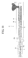
- an extrusion apparatus 41 including a cylindrical barrel 43; a screw 45 rotatably provided in this barrel 43; a driving source (not shown in the figure) for rotationally driving the screw 45; and a die 50 mounted at the tip end of the above-described screw 45 is known as one example of extrusion apparatuses for forming this type of molded foam.
- a mixture of wood meals, thermoplastic resin, pigment, reinforcing agent, and foaming agent 26b, blended at a predetermined compounding ratio is prepared as a raw-material mixture; this raw-material mixture is supplied into the barrel 43; an extrusion force is applied towards the tip of the screw 45 by rotationally driving the screw 45 through the operation of the driving source to pressure-feed the raw-material mixture while it is being heated and kneaded; and the raw-material mixture is extruded as a melted and plasticized molding material 25a from the tip of the screw 45 into a molding chamber 50a of the die 50, thereby forming a molded foam having a cross-sectional shape equivalent to that of the molding chamber 50a (refer to, for example, Patent Document 1).
- the foaming agent contained in the molding material 25a foams in the barrel 43, and the molding material 25a containing generated air bubbles is extruded into the molding chamber 50a of the die 50.
- the air bubbles collect at the center portion of the molding chamber 50a when the pressure is released in the molding chamber 50a, but also the air bubbles further collect at the center portion (core portion) in the width direction of the molded foam as a result of cooling in the molding chamber 50a, thus generating an internal defect due to an internal void G, which is larger than a so-called "nest.”
- a rectangular shape in cross section of the molded plate cannot be ensured because the central portion of the molded plate swells in both directions in the thickness direction at the center in the width direction along the longitudinal direction, and as a result, the molded plate cannot be used as a product.
- the strength is so low that a molded foam having a quality as high as that of a non-foamed article cannot be manufactured on a commercial basis or is difficult to manufacture even at an experimental level ( Fig. 13 ).
- a saw-toothed groove is formed at the lower side of the molded plate along the longitudinal direction.
- a breaker plate 52 in the form of a screen composed of a plurality of meshes is provided at an inlet of the die 50, as shown in Fig. 12 ; a back pressure (force pushing the molding material back in the extrusion direction) is applied towards the barrel 43 backwards from the breaker plate 52 by extruding the molding material 25a towards the die 50 through the meshes of the breaker plate 52; and the internal pressure of the barrel 43 is increased with this back pressure to inhibit the foaming agent contained in the molding material 25a from foaming in the barrel 43.
- the foaming agent contained in the molding material 25a foams as a result of the pressure being released when the molding material 25a is extruded towards the die 50 through the screen composed of meshes of the breaker plate 52, and the molding material 25a in this state is extruded into the molding chamber 50a and cooled. Therefore, like the conventional means shown in Fig. 11 , air bubbles collect at the center portion (core portion) of the molded foam formed in the molding chamber 50a, and the internal void G shown in Fig. 13 is inevitably produced. This makes it difficult to achieve a molded foam with high strength.
- the present invention has been conceived in light of the above-described known problem, and an object thereof is to provide an extrusion apparatus capable of forming a high-quality molded foam that has micro-airbubbles dispersed uniformly throughout the entirety thereof and that is as robust as a non-foamed article.
- the present invention employs the following means to solve the above-described problem.
- the present invention is an extrusion apparatus 1 in which a molding material 25a is made by heating, kneading, melting, and plasticizing a raw-material mixture 25 including at least foaming agent 26b, and the extrusion apparatus 1 includes an extruder 2 that applies an extrusion force to the molding material to extrude it from a tip of a screw 5; an extrusion die 10 mounted at the tip end of the screw; and a molding die 15 mounted at an outlet 11b of the extrusion die.
- a breaker plate 12 that applies a restraining force counteracting an extrusion force to the molding material 25a extruded from the tip of the screw 5 and that applies a back pressure towards the screw 5 is provided at an outlet 11b of the extrusion die 10
- a core 20 that applies a restraining force counteracting an extrusion force to the molding material 25a extruded from the extrusion die 10 and that applies a back pressure to the molding material 25a in the outlet 11b of the extrusion die 10 is provided at an inlet 15a of the molding die 15.
- the breaker plate 12 at the outlet 11b of the extrusion die 10 applies a restraining force counteracting the extrusion force to the molding material 25a.
- a back pressure is produced towards the screw 5, and this back pressure increases the internal pressure of a barrel 3, thus suppressing foaming from the foaming agent 26b contained in the molding material 25a in the barrel 3.
- the foaming agent 26b can be inhibited from gasifying.
- the core 20 at the inlet 15a of the molding die 15 applies a restraining force counteracting the extrusion force to the molding material 25a.
- a back pressure is applied towards the back (on the breaker plate 12 side) in the extrusion direction of the core 20, and this back pressure increases the internal pressure between the above-described core 20 and the above-described breaker plate 12, thus inhibiting foaming of the foaming agent 26b contained in the molding material 25a located at that portion in the molding material to prevent air bubbles from collecting thereat.
- the breaker plate 12 at the outlet of the extrusion die 10 applies a restraining force counteracting the extrusion force to the molding material 25a.
- a back pressure is applied towards the screw 5, and this back pressure increases the internal pressure of the barrel 3, thus inhibiting foaming of the foaming agent 26b contained in the molding material 25a in the barrel 3.
- the core 20 at the inlet of the molding die 15 further applies a restraining force counteracting the extrusion force to the molding material 25a.
- a back pressure is applied towards the back (on the breaker plate 12 side) in the molding material extrusion direction of the core 20, and this back pressure increases the internal pressure at that portion, thus inhibiting foaming of the foaming agent 26b contained in the molding material 25a located at that portion.
- the breaker plate 12 can have a volume-reducing section 13 including a plurality of slits or holes with cross sections whose volumes decrease gradually from the screw 5 towards the molding die 15, and a back pressure can be produced towards the screw 5 by the plurality of slits or holes of the volume-reducing section 13.
- the volume-reducing section 13 including a plurality of slits or holes in the breaker plate 12 applies a restraining force counteracting the extrusion force to the molding material 25a extruded from the screw 5 to the molding die 15.
- a back pressure is applied towards the screw 5, and this back pressure increases the internal pressure of the barrel 3 to inhibit foaming of the foaming agent 26b contained in the molding material 25a in the barrel 3.
- the core 20 can have a restraining section 22 including a plurality of holes or slits whose volumes decrease gradually from the extrusion die 10 towards the molding die 15, and a back pressure can be applied towards the extrusion die 10 by the plurality of holes or slits of the restraining section.
- the restraining section 22 including a plurality of slits or holes 21b in the core 20 applies a restraining force counteracting the extrusion force to the molding material 25a extruded to the molding die 15 through the core 20, and a back pressure is applied towards the back (extrusion die 10) in the extrusion direction of the molding material 25a of the core 20.
- This back pressure increases the pressure at that portion, thus inhibiting foaming of the foaming agent 26b contained in the molding material 25a located at that portion and preventing air bubbles from collecting thereat.
- the core 20 has a main body 21 with a cross-sectional shape matching a cross-sectional shape of the inlet 15a of the molding die 15, and the plurality of holes 21b or slits of the restraining section 22 are provided throughout the entirety of the main body 21.
- the restraining section 22 including a plurality of holes 21b or slits provided all over the main body 21 of the core 20 applies a restraining force counteracting the extrusion force to the molding material 25a extruded to the molding die 15 through the core 20, and a back pressure is applied towards the back (towards the extrusion die 10) in the extrusion direction of the main body 21 of the core 20.
- This back pressure increases the pressure at that portion, thus inhibiting foaming of the foaming agent 26b contained in the molding material 25a located at that portion.
- the plurality of holes 21 b or the plurality of slits of the restraining section 22 can be constructed to communicate with the lead-in portion 23.
- the molding material 25a extruded from the extrusion die 10 to the molding die 15 through the breaker plate 12 is extruded from the lead-in portion 23 of the main body 21 of the core 20 at the inlet 15a of the molding die 15 into the molding chamber 15c of the molding die 15 through the restraining section 22 including a plurality of holes 21 b or slits.
- the raw-material mixture 25 can be produced by mixing, at a predetermined compounding ratio, foaming agent 26b and, as required, another additive with raw material pellets 26a made by melting, kneading, cooling, crushing, and particle-regulated wood meals, resin, pigment, and reinforcing agent that constitute a raw material of synthetic wood powder, thus manufacturing a foam-molded synthetic wood product.
- the breaker plate 12 at the outlet of the extrusion die 10 applies a restraining force counteracting the extrusion force to the molding material 25a; a back pressure generated towards the screw 5 increases the internal pressure of the barrel 3; the foaming agent 26b contained in the molding material 25a in the barrel 3 is inhibited from foaming; the core 20 at the inlet 15a of the molding die 15 applies a restraining force counteracting the extrusion force to the molding material; this applied restraining force can apply a back pressure between the core 20 and the breaker plate 12 located backwards in the extrusion direction of the molding material 25a of this core 20; this back pressure increases the internal pressure between the core 20 and the above-described breaker plate 12; and the foaming agent 26b contained in the molding material 25a at this portion can be inhibited from foaming.
- the core 20 applies a restraining force counteracting the extrusion force to the molding material 25a extruded to the molding chamber 15c; the pressure of the molding material 25a is increased to increase the density; the molding time of the molded foam is not extended without decreasing the extrusion rate; and the pressure is relatively released while the entire molding chamber 15c is uniformly filled with the molding material 25a. Therefore, micro-airbubbles can be substantially uniformly dispersed all over the molded foam, thus allowing a molded foam having a strength equivalent to that of a desired non-foamed article to be formed.
- the volume-reducing section 13 of the breaker plate 12 applies a restraining force counteracting the extrusion force to the molding material 25a, a back pressure generated towards the screw 5 increases the internal pressure of the barrel 3, and the foaming agent 26b contained in the molding material 25a in the barrel 3 can be inhibited from foaming.
- the volume-reducing section 13 of the core 20 can apply a restraining force counteracting the extrusion force to the molding material 25a extruded to the molding die 15 through the core 20, this restraining force can apply a back pressure towards the back (on the extrusion die 10 side) in the extrusion direction of the core 20, this back pressure can increase the pressure between the above-described core 20 and the breaker plate 12 located towards the back in the extrusion direction of the molding material 25a of this core 20, and the foaming agent 26b contained in the molding material 25a at this portion can be inhibited from foaming.
- the pressure of the molding material 25a extruded to the molding chamber 15c is increased to increase the density of the molding material, and.the rate of extruding the molding material 25a into the molding chamber 15c can be increased.
- the molding rate of the molded foam can be increased, the pressure is relatively released while the entire molding chamber 15c is uniformly filled with the molding material 25a, air bubbles can be dispersed substantially uniformly all over the molded foam formed in the molding chamber 15c, and a molded foam having a strength equivalent to that of a desired non-foamed article can be formed.
- the restraining section 22 including a plurality of slits or holes provided all over the main body 21 of the core 20 applies a restraining force counteracting the extrusion force to the molding material 25a extruded to the molding die 15 through the core 20, this restraining force can apply a back pressure towards the back (on the extrusion die 10 side) in the extrusion direction of the main body 21 of the core 20, this back pressure can increase the pressure at that portion, and the foaming agent 26b contained in the molding material 25a located at that portion can be inhibited from foaming.
- the pressure of the molding material 25a extruded to the molding die 15 through the core can be increased.
- the rate of extruding the molding material into the molding die 15 can be increased, the molding rate of the molded foam can be increased, the pressure is released relatively while the entire molding chamber 15c is uniformly filled with the molding material 25a, air bubbles can be dispersed substantially uniformly all over the molded foam formed in the molding chamber 15c, and a molded foam having a strength equivalent to that of a desired non-foamed article can be formed.
- the molding material 25a extruded from the extrusion die 10 to the molding die 15 through the breaker plate 12 is extruded from the lead-in portion 23 formed in the main body 21 of the core 20 at the inlet of the molding die 15 into the molding chamber 15c of the molding die 15 through the restraining section 22 including a plurality of slits or holes.
- the foaming agent 26b contained in the molding material foams without causing air bubbles to collect in the molding material 25a even at the lead-in portion 23, and the molding material in that state has its pressure increased as a result of its flow being controlled by the restraining section 22 including a plurality of slits or holes in the main body 21 of the core 20 and is then extruded into the molding chamber 15c in this state. Therefore, air bubbles can be dispersed substantially uniformly all over the molded foam formed in the molding chamber 15c, and a molded foam having a strength equivalent to that of a desired non-foamed article can be formed.
- the molding material 25a may be pressure-fed directly from the breaker plate 12 to the restraining section 22 of the core 20.
- the composition of a raw material as described later in Table 1, without causing air bubbles to collect or generating an internal void (nest) G was achieved by experiment. This is probably because a single cell of air bubbles is robust due to the high melt tension and melt viscosity of the raw material resin, inhibiting air bubbles from collecting.
- Figs. 1 to 9 show one embodiment of an extrusion apparatus according to the present invention.
- an extrusion apparatus 1 of this embodiment includes a screw extruder 2 and an extrusion die 10 and a molding die 15 that are detachably attached to this screw extruder 2 and includes the extrusion die 10 mounted forwards in the extrusion direction of the above-described extruder 2, a breaker plate 12 detachably provided on this extrusion die 10, and a core 20 detachably provided on the above-described molding die 15.
- the above-described screw extruder 2 is an extruder including a screw 5 that extrudes a raw-material mixture 25, which is, for example, a melted and plasticized molding material 25a produced by heating, kneading, melting, and plasticizing a mixture of raw material pellets 26a, foaming agent 26b, and, as required, another additive blended at a predetermined compounding ratio, where the raw material pellets 26a are produced by melting, gelling, kneading, cooling, crushing, and size-regulating a mixture of wood meals, resin, pigment, and reinforcing agent serving as a raw material of synthetic wood powder.
- a raw-material mixture 25 is, for example, a melted and plasticized molding material 25a produced by heating, kneading, melting, and plasticizing a mixture of raw material pellets 26a, foaming agent 26b, and, as required, another additive blended at a predetermined compounding ratio, where the raw material pellets 26a are produced by melting, gelling, kn
- the present invention can also be applied to various types of screw extruders, such as a biaxial type, a multiaxial type, or a screw extruder that is a combination of those types.
- the uniaxial screw extruder 2 (hereinafter, referred to as "the extruder 2") includes a barrel 3; the screw 5 rotatably provided in this barrel 3; and a driving source (not shown in the figure) composed of a speed-reducing gear, a motor, and so forth to rotationally drive this screw 5.
- the extrusion die 10 and the molding die 15, described later, are detachably attached to the tip end (forwards in the extrusion direction, to the left in Fig. 1 ) of the barrel 3.
- the barrel 3 has a cylindrical body whose tip in the extrusion direction is open and whose rear end (backwards in the extrusion direction, to the right in Fig. 1 ) is closed.
- a hopper 4 that communicates between the interior and the exterior of the barrel 3 is provided above the rear end, and the raw-material mixture 25 in the form of a mixture of the raw material pellets 26a composed of synthetic wood powder and the foaming agent 26b is supplied into the barrel 3 through this hopper 4.
- heating means such as a band heater, is provided over the entire length of the barrel 3 such that it is wound or wrapped around the barrel 3, and the raw-material mixture 25 supplied into the barrel 3 is heated with this heating means.
- the barrel 3 is divided into a plurality of zones (e.g., a supply zone, a compression zone, and a metering zone) along its entire length and is constructed such that the zones can be temperature-controlled individually with the heating means.
- the screw 5 includes a round-bar-shaped rotating shaft 5a rotatably provided at the center of the barrel 3 and screw sections 5b provided helically around and integrally with this rotating shaft 5a.
- the rear end (to the right in Fig. 1 ) of the rotating shaft 5a protrudes backwards from the rear end of the barrel 3 so that the protruding portion can be linked with the driving source to allow the rotating shaft 5a and the screw sections 5b to be rotationally driven together by the operation of the driving source.
- the area of the barrel 3 in which the screw 5 is disposed includes a supply section 6, disposed on the right side in Fig. 1 , for supplying the raw-material mixture 25; a compression section 7, disposed to the left of this supply section 6 in Fig. 1 , for heating, kneading, and compressing the raw-material mixture 25 supplied from the supply section 6; and a metering section 8, disposed to the left of this compression section 7 in Fig. 1 , for metering the raw-material mixture 25 supplied from the compression section 7.
- the raw-material mixture 25 supplied from the hopper 4 into the barrel 3 is pressure-fed towards the tip of the screw 5 along a groove 5c between the screw sections 5b of the screw 5 while being heated and kneaded in coordination with the supply section 6, the compression section 7, and the metering section 8 of the screw 5.
- the raw-material mixture 25 in the form of the melted and plasticized molding material 25a is pressed out of the barrel 3 from the tip of the screw 5 by the extrusion force applied to the molding material.
- the extrusion die 10 not only rectifies the molding material 25a extruded from the tip of the screw 5 but also supplies the molding material 25a with a desired cross-sectional shape and is detachably attached to the tip end of the barrel 3 with, for example, a bolt.
- the rectifying section 10a is constructed so as to have a cross-sectional shape that decreases the volume gradually from an inlet 11 a of the extrusion die 10 located backwards in the extrusion direction of the molding material 25a towards a rectifying section outlet 10d located forwards in the extrusion direction.
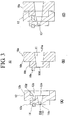
- the size of this rectifying section 10a in the width direction is substantially equivalent to the length in the width direction of an inlet 12e having the total length of a plurality of slits 12d (121d to 121d) that open in the bottom surface of the concave portion 12c of the breaker plate 12, described later, and the height of the rectifying section outlet 10d is equivalent to the height of the above-described inlet 12e ( Figs. 3(B) and 3(C) ).
- an extrusion hole 11 where the inlet 11a of the above-described extrusion die 10 communicates with the opening at the tip of the barrel 3 and an outlet 11b communicates with an inlet 15a of the molding die 15, described later.
- the molding material 25a extruded from the tip of the screw 5 through this extrusion hole 11 is extruded into the molding die 15, described later.
- the extrusion hole 11 in the extrusion die 10 is formed to have a tapered cross-sectional shape (trapezoidal in cross section in this embodiment) so as to decrease its volume from the barrel 3 towards the molding die 15, and the breaker plate 12 is mounted at the outlet 11b of the extrusion hole 11 in this extrusion die 10.
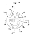
- the breaker plate 12 is a disc-shaped member whose circumferential surface is formed to have a small-diameter portion 12a and a large-diameter portion 12b in two stages and is mounted at the tip end of the barrel 3 such that the rear side in the extrusion direction (hidden side of the drawing in Fig. 2 ) faces the screw 5 and that the front side in the extrusion direction (visible side of the same drawing) faces the molding die 15, described later.
- the circular concave portion 12c of a predetermined depth is provided at the central portion towards the back (on the right side of the drawing in Fig. 3(A) ) in the extrusion direction of the breaker plate 12.
- a plurality of meshes, holes, or slits 12d that penetrate in the extrusion direction passing through the bottom surface of the concave portion 12c and the front surface (on the left side of the drawing in Fig.
- the molding material 25a extruded from the screw 5 is extruded through this plurality of slits 12d into the molding die 15.
- the molding material 25a extruded from the screw 5 is rectified into the concave portion 12c of the breaker plate 12 by the above-described rectifying section 10a of the extrusion die 10, introduced into each of the slits 12d, and extruded to the molding die 15 through each of the slits 12d.
- Each of the slits 12d is formed to have a cross-sectional shape whose volume decreases gradually from the inlet 12e opening in the bottom surface of the concave portion 12c of the breaker plate 12 communicating with the rectifying section outlet 10d of the extrusion die 10 towards the outlet 11b of the extrusion hole 11 towards the front in the extrusion direction.
- These slits 12d produce a back pressure towards the screw 5 backwards in the above-described molding material extrusion direction of the breaker plate 12 and function as a volume-reducing section 13 that inhibits foaming into gas of the foaming agent 26b contained in the molding material 25a melted and plasticized in the barrel 3.
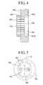
- the six slits 12d except the two slits 121d and 121d at both ends have inclined surfaces at the upper and lower surfaces in Fig. 3(A) and vertical surfaces at both side surfaces in Fig. 5 , that is, are formed in a planar trapezoid that is rectangular in cross section.
- Each of the two slits 121d and 121d at both ends is formed in a planar trapezoid that is substantially rectangular in cross section, having inclined surfaces at the upper and lower surfaces in Fig. 3 (A) and a curved surface at the left side surface or the right side surface in Fig. 5 .
- a plurality of insertion holes 12f that penetrate in the front/back direction of the above-described molding material extrusion direction are provided at the periphery of the breaker plate 12, and the breaker plate 12 is detachably mounted at the outlet 11b of the extrusion hole 11 in the extrusion die 10 with, for example, bolts by means of this plurality of insertion holes 12f.
- Reference numeral 14 in Figs. 2 and 3(A) denotes a pin, which is a member attached by insertion into a pin hole provided on the extrusion die 10 end wall of the breaker plate 12 to determine the mounting position relative thereto.
- 12g denotes a pin hole provided in the breaker plate 12, and a pin 10e of the rectifying section 10a is attached by insertion into this pin hole for positioning ( Fig. 3(B) ).
- each slit is formed to be trapezoidal in cross section, the shape is not limited to a trapezoid in cross section. Any shape that allows the volume to decrease gradually from back to front in the extrusion direction is acceptable.
- each hole is not limited to a slit. Each hole may be a circular or elliptical hole so that the volume decreases gradually in the above-described direction.
- the molding die 15 further rectifies the molding material 25a extruded through the breaker plate 12 at the outlet 11b of the extrusion hole 11 in the extrusion die 10 and produces a desired cross-sectional shape. As shown in Fig. 1 , the molding die 15 is detachably attached to the outlet 11b of the extrusion hole 11 in the extrusion die 10 with, for example, a bolt.
- the molding die 15 is attached to the outlet 11b of the extrusion hole 11 in the extrusion die 10 so that the inlet 15a communicates with the outlet 11b of the extrusion hole 11 in the extrusion die 10.
- a molding chamber 15c having the same continuous rectangular shape in cross section is provided in the molding die 15.
- the inlet 15a of the molding die 15 is formed to be rectangular in cross section, communicating towards the front in the above-described extrusion direction of the breaker plate 12 provided at the outlet 11b of the extrusion hole 11 in the extrusion die 10.
- the molding chamber 15c which is rectangular in cross section, whose longitudinal size is substantially equivalent to that of the inlet 15a and whose lateral size is larger than that of the inlet 15a, is formed in the molding die 15.
- a take-off machine 35 is provided so as to face an outlet 15b of this molding chamber 15c.
- heating means 16 including, for example, a heater is provided so as to surround the inlet 15a.
- the molding material 25a supplied from the extrusion die 10 to the inlet 15a of the molding die 15 is heated by this heating means 16 to keep the molding material 25a in a desirable melted and plasticized state.
- cooling means 17 including, for example, a cooling tube for distributing a cooling medium is provided so as to surround the molding chamber 15c.
- the molding material 25a extruded into the molding chamber 15c is cooled by this cooling means 17 to form a molded foam matching the cross-sectional shape of the molding chamber 15c.
- the core 20 is provided at the inlet 15a of the molding die 15.
- the core 20 includes a plate-shaped main body 21 with a cross-sectional shape matching the cross-sectional shape of the inlet 15a of the molding die 15; a restraining section 22 and a lead-in portion 23 according to the embodiment in the figure provided in this main body 21; and fixing sections 24 that are provided integrally with this main body 21 to fix the main body 21 to the inlet 15a of the molding die 15 ( Fig. 9 ).
- a concave portion 21 a that has a predetermined depth and that is rectangular in cross section is provided towards the back in the extrusion direction of the main body 21.
- a plurality of holes 21b that penetrate between the bottom surface of the concave portion 2 1 a and the left side surface in the same figure, towards the front in the extrusion direction of the main body 21, is provided in the bottom surface of the above-described concave portion 21a.
- the above-described concave portion 21 a constitutes the lead-in portion 23 that introduces the molding material 25a from the extrusion die 10, and the above-described plurality of holes 21b constitute the restraining section 22 that re-pressurizes the molding material 25a supplied from the above-described lead-in portion 23 and applies a back pressure towards the extrusion die 10.
- the plurality of holes 21b of the restraining section 22 are arranged in three rows in the thickness direction of the main body 21, and the plurality of holes 21 b (21 c, 21 c, and 21d) are provided in each row at regular intervals along the horizontal direction.
- the holes 21d in the center row are provided on the same vertical line, and the holes 21c in the upper row and the holes 21c in the lower row, located in the front and back direction of the drawing, are formed so that the holes 21c and 21c face each other and are arranged between the adjacent holes 21d in the center row, where 18 holes are made in the center row and 17 holes are made in each of the upper and lower rows ( Fig. 7 ).
- the plurality of holes 21b are provided in three rows in the main body 21, the holes 21b may be arranged in two or fewer rows or four or more rows.
- slits may be provided instead of holes so that a plurality of slits can constitute the restraining section 22.
- the fixing sections 24 are cylindrical and are provided integrally at the central portion of the upper and lower surfaces of the main body 21 and at both sides thereof at intervals and are provided integrally at the central portion on the right edge of the lower surface of the main body 21 and at both sides thereof so as to correspond to the fixing sections 24 on the upper surface. These fixing sections 24 are made to fit into fixing holes (not shown in the figure) formed at the inlet 15a of the molding die 15 to fix the main body 21 at the inlet 15a of the molding die 15.
- the main body 21 is formed into a flat plate
- the main body 21 can be formed to have various types of shapes, such as a circle, ellipse, or semi-circle, according to the cross-sectional shape of the inlet 15a of the molding die 15.
- the extrusion apparatus 1 with the above-described structure is used while incorporated in the line shown in Fig. 10 as a foam-molded synthetic wood product manufacturing line 60 for treating a composition of the above-described raw material pellets 26a and foaming agent, which is continuous with a manufacturing line 40 for synthetic wood powder, which constitutes the raw material pellets 26a.
- This synthetic wood powder manufacturing line 40 includes a melt mixer 30; a cooling mixer 31; a size regulation machine 32; and a buffer tank 33.
- the foam-molded synthetic wood product manufacturing line 60 is constructed by arranging a blender 34, the extrusion apparatus 1 according to this embodiment, and the take-off machine 35 in that order.
- the raw material pellets 26a are manufactured on the synthetic wood powder manufacturing line 40 according to this embodiment.
- wood meals, resin, pigment, reinforcing agent, and so forth, serving as a raw material of synthetic wood powder are delivered into the melt mixer 30 at a predetermined compounding ratio and are then melted and mixed; the raw material 25 melted and mixed by the melt mixer 30 is cooled by the cooling mixer 31; the mixture cooled by the cooling mixer 31 is crushed by the size regulation machine 32 to perform size-regulation into a predetermined grain size; and the raw material pellets 26a constituting the synthetic wood powder size-regulated into a predetermined grain size by the size regulation machine 32 are stocked in the buffer tank 33.
- the raw material pellets 26a are delivered from the buffer tank 33 to the blender 34 (e.g., a tilting mixer) of the foam-molded synthetic wood product manufacturing line 60; the foaming agent 26b is delivered from another line into the blender 34; the raw material pellets 26a and the foaming agent 26b are dry-blended at a predetermined compounding ratio to prepare the raw-material mixture 25; and the raw-material mixture 25 is supplied to the extrusion apparatus 1 according to this embodiment.
- the blender 34 e.g., a tilting mixer
- a mixture with a compounding ratio of wood meals 50 to 200 ⁇ m); 51 to 53%, resin (thermoplastic resin) (random polypropylene; 18 to 20%, HDPE; 25%), pigment (iron oxide type); 3%, reinforcing agent (maleic modified polypropylene); 0.5%, and foaming agent (inorganic foaming-agent masterbatch); 0.5% is used.
- resin thermoplastic resin
- resin random polypropylene
- HDPE high density polyethylene
- pigment iron oxide type
- reinforcing agent maleic modified polypropylene
- foaming agent inorganic foaming-agent masterbatch
- homopolypropylene, block polypropylene, or Containers/Packaging Recycling Act polypropylene may be used.
- METABLEN trade name, Mitsubishi Rayon Co., Ltd.
- foaming agent MB3064 (manufactured by Sankyo Kasei Co., Ltd.) or polythlene EE405F (manufactured by Eiwa Chemical Ind. Co., Ltd.) may be used.
- MB3064 manufactured by Sankyo Kasei Co., Ltd.
- polythlene EE405F manufactured by Eiwa Chemical Ind. Co., Ltd.
- the raw-material mixture 25 is supplied into the barrel 3 of the extruder 2 of the extrusion apparatus 1 through the hopper 4; the screw 5 is rotationally driven by the operation of the driving source to supply the raw-material mixture 25 from the hopper 4 into the barrel 3; and an extrusion force is applied towards the tip of the screw 5 along the groove 5c at the screw sections 5b of the screw 5 while the raw-material mixture 25 is being heated and kneaded in coordination with the operation of the heating means and the screw 5 to pressure-feed the raw-material mixture 25, thereby forming the melted and plasticized molding material 25a.
- this melted and plasticized molding material 25a is extruded from the tip of the screw 5 into the extrusion hole 11 in the extrusion die 10, extruded into the molding die 15 through the plurality of slits 12d in the breaker plate 12 at the outlet 11b of the extrusion hole 11, introduced into the molding chamber 15c of the molding die 15 through the plurality of holes 21b in the core 20 at the inlet 15a of the molding die 15, pressed out of the molding die 15 from the outlet 15b of the molding chamber 15c, and transferred to the take-off machine 35 provided adjacent to the extruder 2.
- the density of the molded product in the molding chamber 15c is adjusted by the take-off machine 35 at a predetermined take-off rate to form a desired molded foam.
- the molding material 25a extruded from the tip of the screw 5 into the extrusion hole 11 in the extrusion die 10 is introduced to the breaker plate 12 at the outlet 11b through the extrusion hole 11, introduced from the concave portion 12c towards the back in the extrusion direction of the breaker plate 12 to the plurality of slits 12d in the volume-reducing section 13, and extruded to the inlet 15a in the molding die 15 through the plurality of slits 12d.
- the plurality of slits 12d in the volume-reducing section 13 produce a back pressure inside the barrel 3 to increase the internal pressure of the barrel 3.
- the foaming agent 26b contained in the molding material 25a is inhibited from foaming in the barrel 3 and in the extrusion hole 11 of the extrusion die 10, thereby allowing the stable molding material 25a to be supplied from the extrusion die 10 to the molding die 15.
- the molding material 25a extruded to the inlet 15a of the molding die 15 through the plurality of slits 12d in the breaker plate 12 is introduced to the main body 21 of the core 20 provided at the inlet 15a of the molding die 15, introduced from the lead-in portion 23 defined by the concave portion 21a of the main body 21 into the plurality of holes 21b in the restraining section 22, and extruded into the molding chamber 15c of the molding die 15 through the plurality of holes 21b.
- the molding material 25a extruded from the plurality of slits 12d in the breaker plate 12 towards the extrusion die 10 is supplied with a back pressure by the plurality of holes 21b in the restraining section 22 to increase the pressure of the molding material 25a located at that portion. Therefore, the foaming agent contained in the molding material 25a located at that portion is inhibited from foaming.
- the molding material 25a whose foaming agent 26b has been inhibited from foaming between the main body 21 of the core 20 and the breaker plate 12 is extruded into the molding chamber 15c of the molding die 15 through the plurality of holes 21b in the restraining section 22 of the main body 21 of the core 20, the extrusion force of the extruded material is restricted between the core 20 and the breaker plate 12 located towards the back in the molding material 25a extrusion direction of this core 20, thereby increasing the pressure again.
- This molding material 25a with increased pressure is extruded into the molding chamber 15c, and the pressure is relatively released in the molding chamber 15c to uniformly disperse the molding material 25a all over the molding chamber 15c.
- the molding material 25a is extruded into the molding chamber 15c through the plurality of holes 21b arranged uniformly in the main body 21, the pressure of the molding material 25a is relatively released in the molding chamber 15c, and when the foaming agent is to be made to foam, air bubbles are dispersed substantially uniformly all over the molded foam formed in the molding chamber 15c.
- air bubbles that cause an internal void G to be generated do not collect at the core portion (center portion) of the molded foam formed in the molding chamber 15c, and a molded foam that has air bubbles dispersed uniformly throughout and has strength equivalent to that of a desired non-foamed article can be achieved.
- the molding material 25a to be extruded into the molding chamber 15c is extruded into the molding chamber 15c with its pressure increased, the rate of extruding the molding material 25a into the molding chamber 15c can be increased, and therefore, the molding rate of the molded foam can be increased, allowing the productivity to be enhanced greatly.
- the material is not limited to this mixture. Instead, the present invention can be applied to extrusion molding of materials made of various other types of foaming agents.
Landscapes
- Engineering & Computer Science (AREA)
- Mechanical Engineering (AREA)
- Extrusion Moulding Of Plastics Or The Like (AREA)
- Molding Of Porous Articles (AREA)
Abstract
Description
- The present invention relates to extrusion apparatuses and, in particular, to an extrusion apparatus effective in forming various types of molded product injected or extruded by such as injection or extrusion foam molding (hereinafter called "molded foam") used for building materials, automobile interior/exterior materials, and so forth, particularly a molded product in the form of foamed synthetic wood board.
- As shown in
Fig. 11 , anextrusion apparatus 41 including acylindrical barrel 43; ascrew 45 rotatably provided in thisbarrel 43; a driving source (not shown in the figure) for rotationally driving thescrew 45; and adie 50 mounted at the tip end of the above-describedscrew 45 is known as one example of extrusion apparatuses for forming this type of molded foam. - In order to form a molded foam using the
extrusion apparatus 41 with such a structure, for example, a mixture of wood meals, thermoplastic resin, pigment, reinforcing agent, andfoaming agent 26b, blended at a predetermined compounding ratio, is prepared as a raw-material mixture; this raw-material mixture is supplied into thebarrel 43; an extrusion force is applied towards the tip of thescrew 45 by rotationally driving thescrew 45 through the operation of the driving source to pressure-feed the raw-material mixture while it is being heated and kneaded; and the raw-material mixture is extruded as a melted and plasticizedmolding material 25a from the tip of thescrew 45 into amolding chamber 50a of thedie 50, thereby forming a molded foam having a cross-sectional shape equivalent to that of themolding chamber 50a (refer to, for example, Patent Document 1). - Information on prior art references of the present invention is as follows.
- Patent Document 1: Japanese Patent KOKAI (LOPI) No.
8-118452 - Patent Document 2: Japanese Patent KOKAI (LOPI) No.
2002-273778 - However, when a molded foam is formed using the
extrusion apparatus 41 with such a structure, the foaming agent contained in themolding material 25a foams in thebarrel 43, and themolding material 25a containing generated air bubbles is extruded into themolding chamber 50a of thedie 50. Therefore, not only do the air bubbles collect at the center portion of themolding chamber 50a when the pressure is released in themolding chamber 50a, but also the air bubbles further collect at the center portion (core portion) in the width direction of the molded foam as a result of cooling in themolding chamber 50a, thus generating an internal defect due to an internal void G, which is larger than a so-called "nest." For this reason, a rectangular shape in cross section of the molded plate cannot be ensured because the central portion of the molded plate swells in both directions in the thickness direction at the center in the width direction along the longitudinal direction, and as a result, the molded plate cannot be used as a product. Furthermore, the strength is so low that a molded foam having a quality as high as that of a non-foamed article cannot be manufactured on a commercial basis or is difficult to manufacture even at an experimental level (Fig. 13 ). InFig. 13 , to ensure strength, a saw-toothed groove is formed at the lower side of the molded plate along the longitudinal direction. - On the other hand, in order to solve the above-described problem, a
breaker plate 52 in the form of a screen composed of a plurality of meshes is provided at an inlet of thedie 50, as shown inFig. 12 ; a back pressure (force pushing the molding material back in the extrusion direction) is applied towards thebarrel 43 backwards from thebreaker plate 52 by extruding themolding material 25a towards thedie 50 through the meshes of thebreaker plate 52; and the internal pressure of thebarrel 43 is increased with this back pressure to inhibit the foaming agent contained in themolding material 25a from foaming in thebarrel 43. - However, when a molded foam is formed using the
extrusion apparatus 41 with such a structure, the foaming agent contained in themolding material 25a foams as a result of the pressure being released when themolding material 25a is extruded towards thedie 50 through the screen composed of meshes of thebreaker plate 52, and themolding material 25a in this state is extruded into themolding chamber 50a and cooled. Therefore, like the conventional means shown inFig. 11 , air bubbles collect at the center portion (core portion) of the molded foam formed in themolding chamber 50a, and the internal void G shown inFig. 13 is inevitably produced. This makes it difficult to achieve a molded foam with high strength. - The present invention has been conceived in light of the above-described known problem, and an object thereof is to provide an extrusion apparatus capable of forming a high-quality molded foam that has micro-airbubbles dispersed uniformly throughout the entirety thereof and that is as robust as a non-foamed article.
- Means for solving the problem are described below with reference numerals in the embodiments and examples of the present invention. These reference numerals are intended to clarify the correspondence between the descriptions in the claims and the descriptions in the embodiments and examples of the present invention, and it is needless to say that these reference numerals should not be used to restrictively interpret the technical scope of the claims of the present invention.
- The present invention employs the following means to solve the above-described problem.
- More specifically, the present invention is an
extrusion apparatus 1 in which amolding material 25a is made by heating, kneading, melting, and plasticizing a raw-material mixture 25 including at leastfoaming agent 26b, and theextrusion apparatus 1 includes an extruder 2 that applies an extrusion force to the molding material to extrude it from a tip of ascrew 5; an extrusion die 10 mounted at the tip end of the screw; and a molding die 15 mounted at anoutlet 11b of the extrusion die. Abreaker plate 12 that applies a restraining force counteracting an extrusion force to themolding material 25a extruded from the tip of thescrew 5 and that applies a back pressure towards thescrew 5 is provided at anoutlet 11b of the extrusion die 10, and acore 20 that applies a restraining force counteracting an extrusion force to themolding material 25a extruded from theextrusion die 10 and that applies a back pressure to themolding material 25a in theoutlet 11b of the extrusion die 10 is provided at aninlet 15a of themolding die 15. - According to the
extrusion apparatus 1 of the present invention, when themolding material 25a, including at least thefoaming agent 26b, extruded from the tip of thescrew 5 is to be extruded towards themolding die 15 through the extrusion die 10, thebreaker plate 12 at theoutlet 11b of the extrusion die 10 applies a restraining force counteracting the extrusion force to themolding material 25a. As a result, a back pressure is produced towards thescrew 5, and this back pressure increases the internal pressure of a barrel 3, thus suppressing foaming from thefoaming agent 26b contained in themolding material 25a in the barrel 3. In other words, thefoaming agent 26b can be inhibited from gasifying. - Furthermore, when the
molding material 25a is to be extruded from the extrusion die 10 into themolding die 15 through thebreaker plate 12, thecore 20 at theinlet 15a of themolding die 15 applies a restraining force counteracting the extrusion force to themolding material 25a. As a result, a back pressure is applied towards the back (on thebreaker plate 12 side) in the extrusion direction of thecore 20, and this back pressure increases the internal pressure between the above-describedcore 20 and the above-describedbreaker plate 12, thus inhibiting foaming of thefoaming agent 26b contained in themolding material 25a located at that portion in the molding material to prevent air bubbles from collecting thereat. - In addition, as a result of a restraining force counteracting the extrusion force being applied by the
core 20 to themolding material 25a extruded to amolding chamber 15c, the pressure of themolding material 25a extruded to themolding chamber 15c is increased, the rate of extruding themolding material 25a into themolding chamber 15c is increased, and theentire molding chamber 15c is uniformly filled with themolding material 25a. Then, although themolding material 25a is pressurized in the molding chamber even after being sent into themolding chamber 15c, the pressure is relatively released, thus substantially uniformly dispersing air bubbles all over the molded foam to be formed. - According to the
extrusion apparatus 1 of the present invention, when themolding material 25a, including at least thefoaming agent 26b, extruded from the tip of thescrew 5 is to be extruded towards themolding die 15 through the extrusion die 10, thebreaker plate 12 at the outlet of the extrusion die 10 applies a restraining force counteracting the extrusion force to themolding material 25a. As a result, a back pressure is applied towards thescrew 5, and this back pressure increases the internal pressure of the barrel 3, thus inhibiting foaming of thefoaming agent 26b contained in themolding material 25a in the barrel 3. - Furthermore, when the
molding material 25a is to be extruded from the extrusion die 10 into themolding die 15 through thebreaker plate 12, thecore 20 at the inlet of themolding die 15 further applies a restraining force counteracting the extrusion force to themolding material 25a. As a result, a back pressure is applied towards the back (on thebreaker plate 12 side) in the molding material extrusion direction of thecore 20, and this back pressure increases the internal pressure at that portion, thus inhibiting foaming of thefoaming agent 26b contained in themolding material 25a located at that portion. - In addition, as a result of a restraining force counteracting the extrusion force being applied by the
core 20 to themolding material 25a extruded to themolding chamber 15c, the pressure of themolding material 25a extruded to themolding chamber 15c is increased, the rate of extruding themolding material 25a into themolding chamber 15c is increased, and theentire molding chamber 15c is uniformly filled with themolding material 25a to release the pressure relatively, thus substantially uniformly dispersing air bubbles all over the molded foam formed in themolding chamber 15c. - The
breaker plate 12 can have a volume-reducingsection 13 including a plurality of slits or holes with cross sections whose volumes decrease gradually from thescrew 5 towards themolding die 15, and a back pressure can be produced towards thescrew 5 by the plurality of slits or holes of the volume-reducingsection 13. - According to the
extrusion apparatus 1 of the present invention, the volume-reducingsection 13 including a plurality of slits or holes in thebreaker plate 12 applies a restraining force counteracting the extrusion force to themolding material 25a extruded from thescrew 5 to themolding die 15. As a result, a back pressure is applied towards thescrew 5, and this back pressure increases the internal pressure of the barrel 3 to inhibit foaming of thefoaming agent 26b contained in themolding material 25a in the barrel 3. - Furthermore, the
core 20 can have arestraining section 22 including a plurality of holes or slits whose volumes decrease gradually from the extrusion die 10 towards themolding die 15, and a back pressure can be applied towards the extrusion die 10 by the plurality of holes or slits of the restraining section. - According to the
extrusion apparatus 1 of the present invention, therestraining section 22 including a plurality of slits orholes 21b in thecore 20 applies a restraining force counteracting the extrusion force to themolding material 25a extruded to themolding die 15 through thecore 20, and a back pressure is applied towards the back (extrusion die 10) in the extrusion direction of themolding material 25a of thecore 20. This back pressure increases the pressure at that portion, thus inhibiting foaming of thefoaming agent 26b contained in themolding material 25a located at that portion and preventing air bubbles from collecting thereat. - In addition, as a result of a restraining force counteracting the extrusion force being applied by the
restraining section 22 including a plurality ofholes 21b or slits in thecore 20 to themolding material 25a extruded to themolding die 15 through thecore 20, the pressure of themolding material 25a extruded to themolding chamber 15c is increased, the rate of extruding themolding material 25a into themolding chamber 15c is increased, and theentire molding chamber 15c is uniformly filled with themolding material 25a to release the pressure relatively, thus substantially uniformly dispersing air bubbles all over the molded foam formed in themolding chamber 15c. - Furthermore, the
core 20 has amain body 21 with a cross-sectional shape matching a cross-sectional shape of theinlet 15a of themolding die 15, and the plurality ofholes 21b or slits of therestraining section 22 are provided throughout the entirety of themain body 21. - According to the
extrusion apparatus 1 of the present invention, therestraining section 22 including a plurality ofholes 21b or slits provided all over themain body 21 of thecore 20 applies a restraining force counteracting the extrusion force to themolding material 25a extruded to themolding die 15 through thecore 20, and a back pressure is applied towards the back (towards the extrusion die 10) in the extrusion direction of themain body 21 of thecore 20. This back pressure increases the pressure at that portion, thus inhibiting foaming of thefoaming agent 26b contained in themolding material 25a located at that portion. - In addition, as a result of a restraining force counteracting the extrusion force being applied by the
restraining section 22 including a plurality ofholes 21 b or slits in themain body 21 of thecore 20 to themolding material 25a, the pressure of themolding material 25a extruded to themolding die 15 through thecore 20 is increased, the rate of extruding themolding material 25a to themolding die 15 is increased, and the pressure is released relatively while theentire molding chamber 15c is uniformly filled with themolding material 25a, thus substantially uniformly dispersing air bubbles all over the molded foam formed in themolding chamber 15c. - Furthermore, in the case that a lead-in
portion 23 for themolding material 25a extruded from theextrusion die 10 is provided at themain body 21 of thecore 20, the plurality ofholes 21 b or the plurality of slits of therestraining section 22 can be constructed to communicate with the lead-inportion 23. - According to the
extrusion apparatus 1 of the present invention, themolding material 25a extruded from the extrusion die 10 to themolding die 15 through thebreaker plate 12 is extruded from the lead-inportion 23 of themain body 21 of thecore 20 at theinlet 15a of themolding die 15 into themolding chamber 15c of themolding die 15 through therestraining section 22 including a plurality ofholes 21 b or slits. - Furthermore, the raw-
material mixture 25 can be produced by mixing, at a predetermined compounding ratio,foaming agent 26b and, as required, another additive withraw material pellets 26a made by melting, kneading, cooling, crushing, and particle-regulated wood meals, resin, pigment, and reinforcing agent that constitute a raw material of synthetic wood powder, thus manufacturing a foam-molded synthetic wood product. - As described above, according to the extrusion apparatus described in
Claim 1 of the present invention, thebreaker plate 12 at the outlet of the extrusion die 10 applies a restraining force counteracting the extrusion force to themolding material 25a; a back pressure generated towards thescrew 5 increases the internal pressure of the barrel 3; thefoaming agent 26b contained in themolding material 25a in the barrel 3 is inhibited from foaming; thecore 20 at theinlet 15a of themolding die 15 applies a restraining force counteracting the extrusion force to the molding material; this applied restraining force can apply a back pressure between thecore 20 and thebreaker plate 12 located backwards in the extrusion direction of themolding material 25a of thiscore 20; this back pressure increases the internal pressure between thecore 20 and the above-describedbreaker plate 12; and thefoaming agent 26b contained in themolding material 25a at this portion can be inhibited from foaming. - Furthermore, the
core 20 applies a restraining force counteracting the extrusion force to themolding material 25a extruded to themolding chamber 15c; the pressure of themolding material 25a is increased to increase the density; the molding time of the molded foam is not extended without decreasing the extrusion rate; and the pressure is relatively released while theentire molding chamber 15c is uniformly filled with themolding material 25a. Therefore, micro-airbubbles can be substantially uniformly dispersed all over the molded foam, thus allowing a molded foam having a strength equivalent to that of a desired non-foamed article to be formed. - In addition, according to the extrusion apparatus described in Claim 2 of the present invention, the volume-reducing
section 13 of thebreaker plate 12 applies a restraining force counteracting the extrusion force to themolding material 25a, a back pressure generated towards thescrew 5 increases the internal pressure of the barrel 3, and thefoaming agent 26b contained in themolding material 25a in the barrel 3 can be inhibited from foaming. - Furthermore, according to the extrusion apparatus described in Claim 3 of the present invention, the volume-reducing
section 13 of thecore 20 can apply a restraining force counteracting the extrusion force to themolding material 25a extruded to themolding die 15 through thecore 20, this restraining force can apply a back pressure towards the back (on theextrusion die 10 side) in the extrusion direction of thecore 20, this back pressure can increase the pressure between the above-describedcore 20 and thebreaker plate 12 located towards the back in the extrusion direction of themolding material 25a of thiscore 20, and thefoaming agent 26b contained in themolding material 25a at this portion can be inhibited from foaming. - In addition, as a result of a restraining force counteracting the extrusion force being applied by the
restraining section 22 including a plurality of slits or holes in thecore 20 to themolding material 25a extruded to themolding die 15 through thecore 20, the pressure of themolding material 25a extruded to themolding chamber 15c is increased to increase the density of the molding material, and.the rate of extruding themolding material 25a into themolding chamber 15c can be increased. Therefore, the molding rate of the molded foam can be increased, the pressure is relatively released while theentire molding chamber 15c is uniformly filled with themolding material 25a, air bubbles can be dispersed substantially uniformly all over the molded foam formed in themolding chamber 15c, and a molded foam having a strength equivalent to that of a desired non-foamed article can be formed. - Furthermore, according to the extrusion apparatus described in
Claim 4 of the present invention, therestraining section 22 including a plurality of slits or holes provided all over themain body 21 of thecore 20 applies a restraining force counteracting the extrusion force to the moldingmaterial 25a extruded to themolding die 15 through thecore 20, this restraining force can apply a back pressure towards the back (on the extrusion die 10 side) in the extrusion direction of themain body 21 of thecore 20, this back pressure can increase the pressure at that portion, and thefoaming agent 26b contained in themolding material 25a located at that portion can be inhibited from foaming. - In addition, as a result of a restraining force counteracting the extrusion force being applied by the
restraining section 22 including a plurality of slits or holes in themain body 21 1 of thecore 20 to themolding material 25a, the pressure of themolding material 25a extruded to themolding die 15 through the core can be increased. Therefore, the rate of extruding the molding material into themolding die 15 can be increased, the molding rate of the molded foam can be increased, the pressure is released relatively while theentire molding chamber 15c is uniformly filled with themolding material 25a, air bubbles can be dispersed substantially uniformly all over the molded foam formed in themolding chamber 15c, and a molded foam having a strength equivalent to that of a desired non-foamed article can be formed. - Furthermore, according to the extrusion apparatus described in
Claim 5 of the present invention, themolding material 25a extruded from the extrusion die 10 to themolding die 15 through thebreaker plate 12 is extruded from the lead-inportion 23 formed in themain body 21 of thecore 20 at the inlet of themolding die 15 into themolding chamber 15c of themolding die 15 through therestraining section 22 including a plurality of slits or holes. Therefore, some of thefoaming agent 26b contained in the molding material foams without causing air bubbles to collect in themolding material 25a even at the lead-inportion 23, and the molding material in that state has its pressure increased as a result of its flow being controlled by therestraining section 22 including a plurality of slits or holes in themain body 21 of thecore 20 and is then extruded into themolding chamber 15c in this state. Therefore, air bubbles can be dispersed substantially uniformly all over the molded foam formed in themolding chamber 15c, and a molded foam having a strength equivalent to that of a desired non-foamed article can be formed. - It should be noted that instead of forming the above-described lead-in
portion 23 in thecore 20, themolding material 25a may be pressure-fed directly from thebreaker plate 12 to the restrainingsection 22 of thecore 20. Also in this case, the composition of a raw material as described later in Table 1, without causing air bubbles to collect or generating an internal void (nest) G, was achieved by experiment. This is probably because a single cell of air bubbles is robust due to the high melt tension and melt viscosity of the raw material resin, inhibiting air bubbles from collecting. -
-
Fig. 1 is a schematic diagram showing one embodiment of an extrusion apparatus according to the present invention; -
Fig. 2 is a front elevational view of a breaker plate as seen from the front in the extrusion direction; -
Fig. 3(A) is a cross-sectional view taken along line A-A inFig. 2 ,Fig. 3(B) is a cross-sectional view of a rectifying section of an extrusion die taken along line A-A inFig. 2 , andFig. 3(C) is a cross-sectional view of a breaker plate in combination with an extrusion die rectifying section inFig. 2 ; -
Fig. 4 is a cross-sectional view taken along line IV-IV inFig. 2 ; -
Fig. 5 is a rear elevational view of a breaker plate as seen from the back in the extrusion direction; -
Fig. 6 is a plan view of a core; -
Fig. 7 is a front elevational view of a core as seen from the front in the extrusion direction; -
Fig. 8 is a rear elevational view of the core inFig. 6 as seen from the back in the extrusion direction; -
Fig. 9 is a cross-sectional view taken along line IX-IX inFig. 6 ; -
Fig. 10 is an illustration showing one example of a manufacturing line using an extrusion apparatus according to the present inventions; -
Fig. 11 is a schematic diagram showing one example of a conventional extrusion apparatus; -
Fig. 12 is a schematic diagram showing another example of a conventional extrusion apparatus; and -
Fig. 13 is a cross-sectional view of a relevant part showing an internal void (nest) produced in a molded product by a conventional extrusion apparatus. - Embodiments according to the present invention will now be described with reference to the drawings.
-
Figs. 1 to 9 show one embodiment of an extrusion apparatus according to the present invention. - As shown in
Fig. 1 , anextrusion apparatus 1 of this embodiment includes a screw extruder 2 and anextrusion die 10 and amolding die 15 that are detachably attached to this screw extruder 2 and includes the extrusion die 10 mounted forwards in the extrusion direction of the above-described extruder 2, abreaker plate 12 detachably provided on this extrusion die 10, and a core 20 detachably provided on the above-described molding die 15. - The above-described screw extruder 2 is an extruder including a
screw 5 that extrudes a raw-material mixture 25, which is, for example, a melted andplasticized molding material 25a produced by heating, kneading, melting, and plasticizing a mixture ofraw material pellets 26a, foamingagent 26b, and, as required, another additive blended at a predetermined compounding ratio, where theraw material pellets 26a are produced by melting, gelling, kneading, cooling, crushing, and size-regulating a mixture of wood meals, resin, pigment, and reinforcing agent serving as a raw material of synthetic wood powder. - Although this embodiment is described by way of an example where the
extrusion apparatus 1 according to the present invention is applied to the uniaxial screw extruder 2, the present invention can also be applied to various types of screw extruders, such as a biaxial type, a multiaxial type, or a screw extruder that is a combination of those types. - The uniaxial screw extruder 2 (hereinafter, referred to as "the extruder 2") includes a barrel 3; the
screw 5 rotatably provided in this barrel 3; and a driving source (not shown in the figure) composed of a speed-reducing gear, a motor, and so forth to rotationally drive thisscrew 5. The extrusion die 10 and the molding die 15, described later, are detachably attached to the tip end (forwards in the extrusion direction, to the left inFig. 1 ) of the barrel 3. - The barrel 3 has a cylindrical body whose tip in the extrusion direction is open and whose rear end (backwards in the extrusion direction, to the right in
Fig. 1 ) is closed. Ahopper 4 that communicates between the interior and the exterior of the barrel 3 is provided above the rear end, and the raw-material mixture 25 in the form of a mixture of theraw material pellets 26a composed of synthetic wood powder and thefoaming agent 26b is supplied into the barrel 3 through thishopper 4. - At the outer circumferential portion of the barrel 3, heating means (not shown in the figure), such as a band heater, is provided over the entire length of the barrel 3 such that it is wound or wrapped around the barrel 3, and the raw-
material mixture 25 supplied into the barrel 3 is heated with this heating means. The barrel 3 is divided into a plurality of zones (e.g., a supply zone, a compression zone, and a metering zone) along its entire length and is constructed such that the zones can be temperature-controlled individually with the heating means. - The
screw 5 includes a round-bar-shapedrotating shaft 5a rotatably provided at the center of the barrel 3 and screwsections 5b provided helically around and integrally with thisrotating shaft 5a. The rear end (to the right inFig. 1 ) of therotating shaft 5a protrudes backwards from the rear end of the barrel 3 so that the protruding portion can be linked with the driving source to allow therotating shaft 5a and thescrew sections 5b to be rotationally driven together by the operation of the driving source. - The area of the barrel 3 in which the
screw 5 is disposed includes asupply section 6, disposed on the right side inFig. 1 , for supplying the raw-material mixture 25; acompression section 7, disposed to the left of thissupply section 6 inFig. 1 , for heating, kneading, and compressing the raw-material mixture 25 supplied from thesupply section 6; and ametering section 8, disposed to the left of thiscompression section 7 inFig. 1 , for metering the raw-material mixture 25 supplied from thecompression section 7. - When the
screw 5 is rotationally driven by the operation of the driving source, the raw-material mixture 25 supplied from thehopper 4 into the barrel 3 is pressure-fed towards the tip of thescrew 5 along agroove 5c between thescrew sections 5b of thescrew 5 while being heated and kneaded in coordination with thesupply section 6, thecompression section 7, and themetering section 8 of thescrew 5. Thus, the raw-material mixture 25 in the form of the melted andplasticized molding material 25a is pressed out of the barrel 3 from the tip of thescrew 5 by the extrusion force applied to the molding material. - The extrusion die 10 not only rectifies the
molding material 25a extruded from the tip of thescrew 5 but also supplies themolding material 25a with a desired cross-sectional shape and is detachably attached to the tip end of the barrel 3 with, for example, a bolt. - A rectifying
section 10a that rectifies and sends themolding material 25a to thebreaker plate 12, described later, is fixed in an engaged manner in the extrusion die 10. In therectifying section 10a, a small-diameter portion 10c of a corresponding outer circumferential shape that compactedly fits into aconcave portion 12c of thebreaker plate 12, described later, is formed integrally with a large-diameter portion 10b. The rectifyingsection 10a is constructed so as to have a cross-sectional shape that decreases the volume gradually from aninlet 11 a of the extrusion die 10 located backwards in the extrusion direction of themolding material 25a towards a rectifyingsection outlet 10d located forwards in the extrusion direction. The size of thisrectifying section 10a in the width direction is substantially equivalent to the length in the width direction of aninlet 12e having the total length of a plurality ofslits 12d (121d to 121d) that open in the bottom surface of theconcave portion 12c of thebreaker plate 12, described later, and the height of the rectifyingsection outlet 10d is equivalent to the height of the above-describedinlet 12e (Figs. 3(B) and 3(C) ). - Moreover, there is provided an
extrusion hole 11 where theinlet 11a of the above-described extrusion die 10 communicates with the opening at the tip of the barrel 3 and anoutlet 11b communicates with aninlet 15a of the molding die 15, described later. Themolding material 25a extruded from the tip of thescrew 5 through thisextrusion hole 11 is extruded into the molding die 15, described later. - The
extrusion hole 11 in the extrusion die 10 is formed to have a tapered cross-sectional shape (trapezoidal in cross section in this embodiment) so as to decrease its volume from the barrel 3 towards the molding die 15, and thebreaker plate 12 is mounted at theoutlet 11b of theextrusion hole 11 in this extrusion die 10. - As shown in
Figs. 2 to 5 , thebreaker plate 12 is a disc-shaped member whose circumferential surface is formed to have a small-diameter portion 12a and a large-diameter portion 12b in two stages and is mounted at the tip end of the barrel 3 such that the rear side in the extrusion direction (hidden side of the drawing inFig. 2 ) faces thescrew 5 and that the front side in the extrusion direction (visible side of the same drawing) faces the molding die 15, described later. - As shown in
Figs. 3 to 5 , the circularconcave portion 12c of a predetermined depth is provided at the central portion towards the back (on the right side of the drawing inFig. 3(A) ) in the extrusion direction of thebreaker plate 12. At the center portion of thisconcave portion 12c, there are provided a plurality of meshes, holes, orslits 12d (eightslits 12d (, 121d in this embodiment) that penetrate in the extrusion direction passing through the bottom surface of theconcave portion 12c and the front surface (on the left side of the drawing inFig. 3(A) ) of thebreaker plate 12, and themolding material 25a extruded from thescrew 5 is extruded through this plurality ofslits 12d into the molding die 15. In this case, themolding material 25a extruded from thescrew 5 is rectified into theconcave portion 12c of thebreaker plate 12 by the above-describedrectifying section 10a of the extrusion die 10, introduced into each of theslits 12d, and extruded to the molding die 15 through each of theslits 12d. - Each of the
slits 12d is formed to have a cross-sectional shape whose volume decreases gradually from theinlet 12e opening in the bottom surface of theconcave portion 12c of thebreaker plate 12 communicating with the rectifyingsection outlet 10d of the extrusion die 10 towards theoutlet 11b of theextrusion hole 11 towards the front in the extrusion direction. Theseslits 12d produce a back pressure towards thescrew 5 backwards in the above-described molding material extrusion direction of thebreaker plate 12 and function as a volume-reducingsection 13 that inhibits foaming into gas of thefoaming agent 26b contained in themolding material 25a melted and plasticized in the barrel 3. - In this case, of the eight
slits 12d, the sixslits 12d except the twoslits Fig. 3(A) and vertical surfaces at both side surfaces inFig. 5 , that is, are formed in a planar trapezoid that is rectangular in cross section. Each of the twoslits Fig. 3 (A) and a curved surface at the left side surface or the right side surface inFig. 5 . - A plurality of
insertion holes 12f that penetrate in the front/back direction of the above-described molding material extrusion direction are provided at the periphery of thebreaker plate 12, and thebreaker plate 12 is detachably mounted at theoutlet 11b of theextrusion hole 11 in the extrusion die 10 with, for example, bolts by means of this plurality ofinsertion holes 12f. -
Reference numeral 14 inFigs. 2 and3(A) denotes a pin, which is a member attached by insertion into a pin hole provided on the extrusion die 10 end wall of thebreaker plate 12 to determine the mounting position relative thereto. 12g denotes a pin hole provided in thebreaker plate 12, and apin 10e of therectifying section 10a is attached by insertion into this pin hole for positioning (Fig. 3(B) ). - Although in this embodiment the eight
slits 12d (12d, 121d) are provided in thebreaker plate 12 as described above, eight or fewer slits or nine or more slits may be provided. Furthermore, although each slit is formed to be trapezoidal in cross section, the shape is not limited to a trapezoid in cross section. Any shape that allows the volume to decrease gradually from back to front in the extrusion direction is acceptable. In addition, each hole is not limited to a slit. Each hole may be a circular or elliptical hole so that the volume decreases gradually in the above-described direction. - The molding die 15 further rectifies the
molding material 25a extruded through thebreaker plate 12 at theoutlet 11b of theextrusion hole 11 in the extrusion die 10 and produces a desired cross-sectional shape. As shown inFig. 1 , the molding die 15 is detachably attached to theoutlet 11b of theextrusion hole 11 in the extrusion die 10 with, for example, a bolt. - In this case, the molding die 15 is attached to the
outlet 11b of theextrusion hole 11 in the extrusion die 10 so that theinlet 15a communicates with theoutlet 11b of theextrusion hole 11 in the extrusion die 10. Amolding chamber 15c having the same continuous rectangular shape in cross section is provided in the molding die 15. When themolding material 25a extruded from the extrusion die 10 through thebreaker plate 12 is introduced into thismolding chamber 15c, themolding material 25a is supplied with a desired cross-sectional shape, that is, is formed into a flat plate having the same continuous rectangular shape in cross section in this embodiment, like themolding chamber 15c. - The
inlet 15a of the molding die 15 is formed to be rectangular in cross section, communicating towards the front in the above-described extrusion direction of thebreaker plate 12 provided at theoutlet 11b of theextrusion hole 11 in the extrusion die 10. Continued with thisinlet 15a, themolding chamber 15c, which is rectangular in cross section, whose longitudinal size is substantially equivalent to that of theinlet 15a and whose lateral size is larger than that of theinlet 15a, is formed in the molding die 15. Furthermore, a take-off machine 35, described later, is provided so as to face anoutlet 15b of thismolding chamber 15c. - Around the
inlet 15a of the molding die 15, heating means 16 including, for example, a heater is provided so as to surround theinlet 15a. Themolding material 25a supplied from the extrusion die 10 to theinlet 15a of the molding die 15 is heated by this heating means 16 to keep themolding material 25a in a desirable melted and plasticized state. - Around the
molding chamber 15c of the molding die 15, cooling means 17 including, for example, a cooling tube for distributing a cooling medium is provided so as to surround themolding chamber 15c. Themolding material 25a extruded into themolding chamber 15c is cooled by this cooling means 17 to form a molded foam matching the cross-sectional shape of themolding chamber 15c. - The
core 20 is provided at theinlet 15a of the molding die 15. - The
core 20 includes a plate-shapedmain body 21 with a cross-sectional shape matching the cross-sectional shape of theinlet 15a of the molding die 15; a restrainingsection 22 and a lead-inportion 23 according to the embodiment in the figure provided in thismain body 21; and fixingsections 24 that are provided integrally with thismain body 21 to fix themain body 21 to theinlet 15a of the molding die 15 (Fig. 9 ). - A
concave portion 21 a that has a predetermined depth and that is rectangular in cross section is provided towards the back in the extrusion direction of themain body 21. A plurality ofholes 21b that penetrate between the bottom surface of the concave portion 2 1 a and the left side surface in the same figure, towards the front in the extrusion direction of themain body 21, is provided in the bottom surface of the above-describedconcave portion 21a. The above-describedconcave portion 21 a constitutes the lead-inportion 23 that introduces themolding material 25a from the extrusion die 10, and the above-described plurality ofholes 21b constitute the restrainingsection 22 that re-pressurizes themolding material 25a supplied from the above-described lead-inportion 23 and applies a back pressure towards the extrusion die 10. - The plurality of
holes 21b of the restrainingsection 22 are arranged in three rows in the thickness direction of themain body 21, and the plurality ofholes 21 b (21 c, 21 c, and 21d) are provided in each row at regular intervals along the horizontal direction. In this case, theholes 21d in the center row are provided on the same vertical line, and theholes 21c in the upper row and theholes 21c in the lower row, located in the front and back direction of the drawing, are formed so that theholes adjacent holes 21d in the center row, where 18 holes are made in the center row and 17 holes are made in each of the upper and lower rows (Fig. 7 ). - Although in this embodiment the plurality of
holes 21b are provided in three rows in themain body 21, theholes 21b may be arranged in two or fewer rows or four or more rows. Alternatively, slits may be provided instead of holes so that a plurality of slits can constitute the restrainingsection 22. - The fixing
sections 24 are cylindrical and are provided integrally at the central portion of the upper and lower surfaces of themain body 21 and at both sides thereof at intervals and are provided integrally at the central portion on the right edge of the lower surface of themain body 21 and at both sides thereof so as to correspond to the fixingsections 24 on the upper surface. These fixingsections 24 are made to fit into fixing holes (not shown in the figure) formed at theinlet 15a of the molding die 15 to fix themain body 21 at theinlet 15a of the molding die 15. - Although in this embodiment the
main body 21 is formed into a flat plate, themain body 21 can be formed to have various types of shapes, such as a circle, ellipse, or semi-circle, according to the cross-sectional shape of theinlet 15a of the molding die 15. - In this embodiment, the
extrusion apparatus 1 with the above-described structure is used while incorporated in the line shown inFig. 10 as a foam-molded synthetic woodproduct manufacturing line 60 for treating a composition of the above-describedraw material pellets 26a and foaming agent, which is continuous with amanufacturing line 40 for synthetic wood powder, which constitutes theraw material pellets 26a. - This synthetic wood
powder manufacturing line 40 includes amelt mixer 30; a coolingmixer 31; asize regulation machine 32; and abuffer tank 33. The foam-molded synthetic woodproduct manufacturing line 60 is constructed by arranging ablender 34, theextrusion apparatus 1 according to this embodiment, and the take-off machine 35 in that order. - To form a desired molded foam using the
manufacturing line 60 with such a structure, theraw material pellets 26a are manufactured on the synthetic woodpowder manufacturing line 40 according to this embodiment. - More specifically, wood meals, resin, pigment, reinforcing agent, and so forth, serving as a raw material of synthetic wood powder, are delivered into the
melt mixer 30 at a predetermined compounding ratio and are then melted and mixed; theraw material 25 melted and mixed by themelt mixer 30 is cooled by the coolingmixer 31; the mixture cooled by the coolingmixer 31 is crushed by thesize regulation machine 32 to perform size-regulation into a predetermined grain size; and theraw material pellets 26a constituting the synthetic wood powder size-regulated into a predetermined grain size by thesize regulation machine 32 are stocked in thebuffer tank 33. - Next, the
raw material pellets 26a are delivered from thebuffer tank 33 to the blender 34 (e.g., a tilting mixer) of the foam-molded synthetic woodproduct manufacturing line 60; thefoaming agent 26b is delivered from another line into theblender 34; theraw material pellets 26a and thefoaming agent 26b are dry-blended at a predetermined compounding ratio to prepare the raw-material mixture 25; and the raw-material mixture 25 is supplied to theextrusion apparatus 1 according to this embodiment. - Here, as shown in Table 1, as a raw material of synthetic wood powder, a mixture with a compounding ratio of wood meals (50 to 200 µm); 51 to 53%, resin (thermoplastic resin) (random polypropylene; 18 to 20%, HDPE; 25%), pigment (iron oxide type); 3%, reinforcing agent (maleic modified polypropylene); 0.5%, and foaming agent (inorganic foaming-agent masterbatch); 0.5% is used.
- As the resin, homopolypropylene, block polypropylene, or Containers/Packaging Recycling Act polypropylene may be used. As the reinforcing agent, METABLEN (trade name, Mitsubishi Rayon Co., Ltd.), which is an additive for increasing the melt viscosity and melt tension of resin, may be used. As the foaming agent, MB3064 (manufactured by Sankyo Kasei Co., Ltd.) or polythlene EE405F (manufactured by Eiwa Chemical Ind. Co., Ltd.) may be used.
[Table 1] Composition Table Kind of material Grade Part No. Compounding ratio (%) Wood meals 50 to 200 µm Kaneki, A-100 51 to 53 Resin Random PP Recycled pulverized product (SunAllomer Ltd., PB222A) 18 to 20 HDPE Pulverized bottle product 25 Pigment Iron oxide type Toda Kogyo Corp., Brown 710 3 Reinforcing agent Maleic modified PP Sanyo Chemical Industries, Ltd., Yumex 1010 0.5 Foaming Agent Inorganic foaming-agent masterbatch Sankyo Kasei Co., Ltd., MB3074 0.5 - Now, as shown in
Fig. 1 , the raw-material mixture 25 is supplied into the barrel 3 of the extruder 2 of theextrusion apparatus 1 through thehopper 4; thescrew 5 is rotationally driven by the operation of the driving source to supply the raw-material mixture 25 from thehopper 4 into the barrel 3; and an extrusion force is applied towards the tip of thescrew 5 along thegroove 5c at thescrew sections 5b of thescrew 5 while the raw-material mixture 25 is being heated and kneaded in coordination with the operation of the heating means and thescrew 5 to pressure-feed the raw-material mixture 25, thereby forming the melted andplasticized molding material 25a. - Then, this melted and
plasticized molding material 25a is extruded from the tip of thescrew 5 into theextrusion hole 11 in the extrusion die 10, extruded into the molding die 15 through the plurality ofslits 12d in thebreaker plate 12 at theoutlet 11b of theextrusion hole 11, introduced into themolding chamber 15c of the molding die 15 through the plurality ofholes 21b in the core 20 at theinlet 15a of the molding die 15, pressed out of the molding die 15 from theoutlet 15b of themolding chamber 15c, and transferred to the take-off machine 35 provided adjacent to the extruder 2. The density of the molded product in themolding chamber 15c is adjusted by the take-off machine 35 at a predetermined take-off rate to form a desired molded foam. - In this case, the
molding material 25a extruded from the tip of thescrew 5 into theextrusion hole 11 in the extrusion die 10 is introduced to thebreaker plate 12 at theoutlet 11b through theextrusion hole 11, introduced from theconcave portion 12c towards the back in the extrusion direction of thebreaker plate 12 to the plurality ofslits 12d in the volume-reducingsection 13, and extruded to theinlet 15a in the molding die 15 through the plurality ofslits 12d. At this time, the plurality ofslits 12d in the volume-reducingsection 13 produce a back pressure inside the barrel 3 to increase the internal pressure of the barrel 3. Therefore, thefoaming agent 26b contained in themolding material 25a is inhibited from foaming in the barrel 3 and in theextrusion hole 11 of the extrusion die 10, thereby allowing thestable molding material 25a to be supplied from the extrusion die 10 to the molding die 15. - Furthermore, the
molding material 25a extruded to theinlet 15a of the molding die 15 through the plurality ofslits 12d in thebreaker plate 12 is introduced to themain body 21 of the core 20 provided at theinlet 15a of the molding die 15, introduced from the lead-inportion 23 defined by theconcave portion 21a of themain body 21 into the plurality ofholes 21b in the restrainingsection 22, and extruded into themolding chamber 15c of the molding die 15 through the plurality ofholes 21b. At this time, themolding material 25a extruded from the plurality ofslits 12d in thebreaker plate 12 towards the extrusion die 10 is supplied with a back pressure by the plurality ofholes 21b in the restrainingsection 22 to increase the pressure of themolding material 25a located at that portion. Therefore, the foaming agent contained in themolding material 25a located at that portion is inhibited from foaming. - Furthermore, when the
molding material 25a whosefoaming agent 26b has been inhibited from foaming between themain body 21 of thecore 20 and thebreaker plate 12 is extruded into themolding chamber 15c of the molding die 15 through the plurality ofholes 21b in the restrainingsection 22 of themain body 21 of the core 20, the extrusion force of the extruded material is restricted between the core 20 and thebreaker plate 12 located towards the back in themolding material 25a extrusion direction of thiscore 20, thereby increasing the pressure again. Thismolding material 25a with increased pressure is extruded into themolding chamber 15c, and the pressure is relatively released in themolding chamber 15c to uniformly disperse themolding material 25a all over themolding chamber 15c. - In this case, because the
molding material 25a is extruded into themolding chamber 15c through the plurality ofholes 21b arranged uniformly in themain body 21, the pressure of themolding material 25a is relatively released in themolding chamber 15c, and when the foaming agent is to be made to foam, air bubbles are dispersed substantially uniformly all over the molded foam formed in themolding chamber 15c. - Therefore, air bubbles that cause an internal void G to be generated do not collect at the core portion (center portion) of the molded foam formed in the
molding chamber 15c, and a molded foam that has air bubbles dispersed uniformly throughout and has strength equivalent to that of a desired non-foamed article can be achieved. - Furthermore, because the
molding material 25a to be extruded into themolding chamber 15c is extruded into themolding chamber 15c with its pressure increased, the rate of extruding themolding material 25a into themolding chamber 15c can be increased, and therefore, the molding rate of the molded foam can be increased, allowing the productivity to be enhanced greatly. - Although a mixture of wood meals, thermoplastic resin, pigment, reinforcing agent, and foaming agent is used as the raw-
material mixture 25 in the above-described description, the material is not limited to this mixture. Instead, the present invention can be applied to extrusion molding of materials made of various other types of foaming agents.
Claims (6)
- An extrusion apparatus in which a molding material is made by heating, kneading, melting, and plasticizing a raw-material mixture including at least foaming agent, comprising:an extruder that extrudes the molding material from a tip of a screw;an extrusion die mounted at the tip end of the screw; anda molding die mounted at an outlet of the extrusion die, whereina breaker plate that applies a restraining force counteracting an extrusion force to the molding material extruded from the tip of the screw and that applies a back pressure towards the screw is provided at an outlet of the extrusion die, anda core that applies a restraining force counteracting an extrusion force to the molding material extruded from the extrusion die and that applies a back pressure to a space at the outlet of the extrusion die is provided at an inlet of the molding die.
- The extrusion apparatus according to Claim 1, wherein the breaker plate has a volume-reducing section including a plurality of slits or holes whose volumes decrease gradually from the screw towards the molding die, and a back pressure is produced towards the screw by the plurality of slits or holes of the volume-reducing section.
- The extrusion apparatus according to Claim 1 or 2, wherein the core has a restraining section including a plurality of slits or holes whose volumes decrease gradually from the extrusion die towards the molding die, and the molding material between the core and the outlet in the direction toward the extrusion die has a back pressure applied thereto by the plurality of slits or holes of the restraining section.
- The extrusion apparatus according to Claim 3, wherein the core has a main body with a cross-sectional shape matching a cross-sectional shape of the inlet of the molding die, and the plurality of slits or holes of the restraining section are provided throughout the entirety of the main body.
- The extrusion apparatus according to Claim 4, wherein an lead-in portion that introduces the molding material extruded from the extrusion die is provided at the main body of the core, and the plurality of holes or the plurality of slits of the restraining section communicate with the lead-in portion.
- The extrusion apparatus according to one of Claims 1 to 5, wherein the raw-material mixture is produced by mixing foaming agent with raw material pellets made by melting, kneading, cooling, and size-regulating wood meals, thermoplastic resin, pigment, and reinforcing agent that constitute a raw material of synthetic wood powder.
Applications Claiming Priority (2)
| Application Number | Priority Date | Filing Date | Title |
|---|---|---|---|
| JP2008137248 | 2008-05-26 | ||
| PCT/JP2009/002198 WO2009144887A1 (en) | 2008-05-26 | 2009-05-19 | Extrusion apparatus |
Publications (2)
| Publication Number | Publication Date |
|---|---|
| EP2298532A1 true EP2298532A1 (en) | 2011-03-23 |
| EP2298532A4 EP2298532A4 (en) | 2014-07-30 |
Family
ID=41376777
Family Applications (1)
| Application Number | Title | Priority Date | Filing Date |
|---|---|---|---|
| EP09754396.1A Withdrawn EP2298532A4 (en) | 2008-05-26 | 2009-05-19 | EXTRUSION APPARATUS |
Country Status (11)
| Country | Link |
|---|---|
| EP (1) | EP2298532A4 (en) |
| JP (1) | JP4981967B2 (en) |
| KR (1) | KR101009364B1 (en) |
| CN (1) | CN102036801B (en) |
| AU (1) | AU2009252630B2 (en) |
| BR (1) | BRPI0909593A2 (en) |
| CA (1) | CA2726172C (en) |
| MX (1) | MX2010012785A (en) |
| MY (1) | MY159653A (en) |
| RU (1) | RU2478478C2 (en) |
| WO (1) | WO2009144887A1 (en) |
Cited By (1)
| Publication number | Priority date | Publication date | Assignee | Title |
|---|---|---|---|---|
| EP2796262A4 (en) * | 2011-12-20 | 2015-05-27 | Wpc Corp | Woody synthetic powder |
Families Citing this family (13)
| Publication number | Priority date | Publication date | Assignee | Title |
|---|---|---|---|---|
| JP5457933B2 (en) * | 2010-04-28 | 2014-04-02 | Wpcコーポレーション株式会社 | Method for producing composite pellet for extrusion molding, and composite pellet for extrusion produced by the above method |
| KR20130020783A (en) | 2010-04-28 | 2013-02-28 | 더블유피씨 코포레이션 | Method for producing composite pellet for extrusion molding, and composite pellet for extrusion molding produced by the method |
| CN102653129A (en) * | 2012-05-21 | 2012-09-05 | 贵州大学 | Pressure adjusting method and device of handpiece of screw extruder |
| CN102975378A (en) * | 2012-12-10 | 2013-03-20 | 南充市富康塑胶制品厂 | Flame retardant wire-pulling pipe |
| JP5984073B2 (en) * | 2014-03-31 | 2016-09-06 | 東レ株式会社 | Manufacturing apparatus and manufacturing method for liquid crystalline polyester resin pellets |
| CN103964693B (en) * | 2014-04-23 | 2017-03-29 | 宁波荣山新型材料有限公司 | A kind of expanded molding integral process of cryogenic foam glass heat-insulating material |
| CN105538583A (en) * | 2016-02-19 | 2016-05-04 | 孙清涛 | Polygonal continuous forming foaming machine |
| US11712826B2 (en) * | 2019-07-09 | 2023-08-01 | Otrajet Inc. | Injection molding system and injection molding method |
| CN110815771B (en) * | 2019-09-25 | 2021-06-15 | 浙江天之元物流科技有限公司 | Production process of double-spliced air bubble bag |
| KR102411815B1 (en) * | 2021-07-14 | 2022-06-22 | 주식회사 에스텍 | Compressed Oil Harvest |
| CN116039040B (en) * | 2022-12-29 | 2023-07-21 | 金华小飞鱼玩具股份有限公司 | Extrusion molding equipment and molding process for plastic product |
| KR102693125B1 (en) * | 2024-01-24 | 2024-08-08 | (주) 미라이후손관거 | Breaker plate for extruder |
| KR102911816B1 (en) * | 2024-06-11 | 2026-01-13 | 에이치에스엠(주) | T-die orifice |
Family Cites Families (19)
| Publication number | Priority date | Publication date | Assignee | Title |
|---|---|---|---|---|
| CA931720A (en) * | 1969-08-07 | 1973-08-14 | Hayashi Motoshige | Synthetic wood and a method for preparation thereof |
| JPS534229Y2 (en) * | 1972-03-07 | 1978-02-02 | ||
| JPS5829729B2 (en) * | 1977-12-16 | 1983-06-24 | 積水化成品工業株式会社 | Method for manufacturing synthetic wood made of resin foam mainly composed of polypropylene |
| JP3456709B2 (en) * | 1991-05-17 | 2003-10-14 | 日立造船株式会社 | Multi-screw extruder |
| DE4325514C1 (en) * | 1993-07-29 | 1994-10-27 | Schaaf Technologie Gmbh | Cooking extruders for the production of thermally treated biopolymers and processes for cooking extrusion of biopolymers |
| JP2872590B2 (en) * | 1994-10-24 | 1999-03-17 | アイン・エンジニアリング株式会社 | Extrusion molding method and apparatus for hollow resin molded plate |
| JP3404169B2 (en) * | 1995-03-17 | 2003-05-06 | 株式会社神戸製鋼所 | Breaker plate for extruder |
| JPH09109228A (en) * | 1995-10-19 | 1997-04-28 | Beishin Kogyo Kk | Foaming expediting method for foamed synthetic resin molding |
| JPH10272670A (en) * | 1997-03-28 | 1998-10-13 | Beishin Kogyo Kk | Promoting method for foaming of expanded synthetic resin molding |
| US6524420B1 (en) * | 1999-05-28 | 2003-02-25 | General Electric | Composite and process for making |
| JP2001019787A (en) * | 1999-07-05 | 2001-01-23 | Sekisui Plastics Co Ltd | Method for producing plate-like styrene resin foam |
| JP2001026043A (en) | 1999-07-14 | 2001-01-30 | Sumitomo Wiring Syst Ltd | Nozzle structure of extruder |
| JP2001273778A (en) * | 2000-03-27 | 2001-10-05 | Seiko Epson Corp | Memory device, manufacturing method thereof, and memory device recording method |
| JP2002273778A (en) | 2001-03-19 | 2002-09-25 | Sekisui Chem Co Ltd | Method for producing breaker plate and sheet-like molded product |
| JP3667655B2 (en) * | 2001-04-25 | 2005-07-06 | 株式会社ジェイエスピー | Extruded foam composite manufacturing equipment |
| EP1417084A4 (en) * | 2001-08-16 | 2005-05-04 | Ispa Inc | METHOD AND APPARATUS FOR COMPRESSION-INJECTION OF EXTRUDED COMPOSITE |
| JP2004314371A (en) * | 2003-04-15 | 2004-11-11 | Kiriyama Kasei:Kk | WOOD RESIN MOLDED BODY AND EXTRUDING METHOD THEREOF |
| JP2005238554A (en) * | 2004-02-25 | 2005-09-08 | Misawa Homes Co Ltd | Extrusion foam molding method and extrusion foam molding apparatus |
| RU2314918C1 (en) * | 2006-06-29 | 2008-01-20 | Закрытое Акционерное Общество "Юнайтед Бейкерс" | Extruder |
-
2008
- 2008-09-25 KR KR1020080094226A patent/KR101009364B1/en not_active Expired - Fee Related
-
2009
- 2009-05-19 RU RU2010146210/05A patent/RU2478478C2/en not_active IP Right Cessation
- 2009-05-19 MY MYPI2010005290A patent/MY159653A/en unknown
- 2009-05-19 JP JP2010514347A patent/JP4981967B2/en not_active Expired - Fee Related
- 2009-05-19 AU AU2009252630A patent/AU2009252630B2/en not_active Ceased
- 2009-05-19 EP EP09754396.1A patent/EP2298532A4/en not_active Withdrawn
- 2009-05-19 BR BRPI0909593A patent/BRPI0909593A2/en not_active IP Right Cessation
- 2009-05-19 WO PCT/JP2009/002198 patent/WO2009144887A1/en not_active Ceased
- 2009-05-19 CA CA2726172A patent/CA2726172C/en not_active Expired - Fee Related
- 2009-05-19 MX MX2010012785A patent/MX2010012785A/en active IP Right Grant
- 2009-05-19 CN CN2009801188903A patent/CN102036801B/en not_active Expired - Fee Related
Cited By (2)
| Publication number | Priority date | Publication date | Assignee | Title |
|---|---|---|---|---|
| EP2796262A4 (en) * | 2011-12-20 | 2015-05-27 | Wpc Corp | Woody synthetic powder |
| US9505932B2 (en) | 2011-12-20 | 2016-11-29 | Beijing Shengsheng Culture Limited Liability Company | Synthetic wood meal |
Also Published As
| Publication number | Publication date |
|---|---|
| KR101009364B1 (en) | 2011-01-19 |
| CA2726172A1 (en) | 2009-12-03 |
| CA2726172C (en) | 2014-07-22 |
| JP4981967B2 (en) | 2012-07-25 |
| EP2298532A4 (en) | 2014-07-30 |
| CN102036801A (en) | 2011-04-27 |
| AU2009252630B2 (en) | 2012-06-28 |
| AU2009252630A1 (en) | 2009-12-03 |
| KR20090122869A (en) | 2009-12-01 |
| BRPI0909593A2 (en) | 2015-11-17 |
| MX2010012785A (en) | 2010-12-21 |
| RU2478478C2 (en) | 2013-04-10 |
| JPWO2009144887A1 (en) | 2011-10-06 |
| WO2009144887A1 (en) | 2009-12-03 |
| CN102036801B (en) | 2013-08-21 |
| RU2010146210A (en) | 2012-07-10 |
| MY159653A (en) | 2017-01-13 |
Similar Documents
| Publication | Publication Date | Title |
|---|---|---|
| AU2009252630B2 (en) | Extrusion apparatus | |
| EP0952908B1 (en) | Injection molding of microcellular material | |
| US6884823B1 (en) | Injection molding of polymeric material | |
| CN102470597B (en) | Molding material for extrusion foam molding, process for producing same, woody molded foam produced from the molding material, and process and apparatus for producing the woody molded foam | |
| EP1126959B1 (en) | Molded polymeric article | |
| JP7164170B2 (en) | Concrete formwork wall extrusion method and concrete formwork wall extrusion apparatus | |
| EP4585387A2 (en) | Polymer foam articles and methods of making polymer foams | |
| EP1512509B1 (en) | Apparatus for and method of foam molding | |
| JP6621149B2 (en) | Method for extruding a molding plate for concrete formwork and an apparatus for extruding a molding plate for concrete formwork | |
| HK1152508A (en) | Extrusion apparatus | |
| WO2002026485A1 (en) | Thin wall injection molding | |
| JP2007021899A (en) | Extrusion molding apparatus for waste resin mixed with various plastics | |
| HK1166758B (en) | Molding material for extrusion foam molding, process for producing same, woody molded foam produced from the molding material, and process and apparatus for producing the woody molded foam | |
| AU2032602A (en) | Injection molding of microcellular material |
Legal Events
| Date | Code | Title | Description |
|---|---|---|---|
| PUAI | Public reference made under article 153(3) epc to a published international application that has entered the european phase |
Free format text: ORIGINAL CODE: 0009012 |
|
| 17P | Request for examination filed |
Effective date: 20101122 |
|
| AK | Designated contracting states |
Kind code of ref document: A1 Designated state(s): AT BE BG CH CY CZ DE DK EE ES FI FR GB GR HR HU IE IS IT LI LT LU LV MC MK MT NL NO PL PT RO SE SI SK TR |
|
| AX | Request for extension of the european patent |
Extension state: AL BA RS |
|
| DAX | Request for extension of the european patent (deleted) | ||
| A4 | Supplementary search report drawn up and despatched |
Effective date: 20140630 |
|
| RIC1 | Information provided on ipc code assigned before grant |
Ipc: B29C 44/46 20060101ALI20140624BHEP Ipc: B29C 47/70 20060101ALI20140624BHEP Ipc: B29K 105/16 20060101ALI20140624BHEP Ipc: B29C 47/30 20060101ALI20140624BHEP Ipc: B29C 47/08 20060101ALI20140624BHEP Ipc: B29K 105/04 20060101ALI20140624BHEP Ipc: B29C 47/12 20060101AFI20140624BHEP |
|
| STAA | Information on the status of an ep patent application or granted ep patent |
Free format text: STATUS: THE APPLICATION IS DEEMED TO BE WITHDRAWN |
|
| 18D | Application deemed to be withdrawn |
Effective date: 20150128 |