EP2297618B1 - Method and apparatus for reel building and roll runnability in moving web manufacturing - Google Patents
Method and apparatus for reel building and roll runnability in moving web manufacturing Download PDFInfo
- Publication number
- EP2297618B1 EP2297618B1 EP08768372.8A EP08768372A EP2297618B1 EP 2297618 B1 EP2297618 B1 EP 2297618B1 EP 08768372 A EP08768372 A EP 08768372A EP 2297618 B1 EP2297618 B1 EP 2297618B1
- Authority
- EP
- European Patent Office
- Prior art keywords
- cross
- profile
- directional
- property profiles
- profiles
- Prior art date
- Legal status (The legal status is an assumption and is not a legal conclusion. Google has not performed a legal analysis and makes no representation as to the accuracy of the status listed.)
- Active
Links
- 238000000034 method Methods 0.000 title claims description 35
- 238000004519 manufacturing process Methods 0.000 title claims description 8
- 230000004044 response Effects 0.000 claims description 30
- 238000005259 measurement Methods 0.000 claims description 26
- 239000002131 composite material Substances 0.000 claims description 8
- 238000013507 mapping Methods 0.000 claims description 8
- 239000006185 dispersion Substances 0.000 claims description 6
- 238000003491 array Methods 0.000 claims 4
- 230000008569 process Effects 0.000 description 18
- 230000009471 action Effects 0.000 description 9
- 238000003490 calendering Methods 0.000 description 9
- 230000001276 controlling effect Effects 0.000 description 9
- 238000005457 optimization Methods 0.000 description 8
- 238000010438 heat treatment Methods 0.000 description 4
- 230000006698 induction Effects 0.000 description 4
- 239000011159 matrix material Substances 0.000 description 4
- 239000002184 metal Substances 0.000 description 4
- 229920000642 polymer Polymers 0.000 description 4
- 101100225582 Neurospora crassa (strain ATCC 24698 / 74-OR23-1A / CBS 708.71 / DSM 1257 / FGSC 987) nip-1 gene Proteins 0.000 description 3
- 239000013078 crystal Substances 0.000 description 3
- 238000007542 hardness measurement Methods 0.000 description 3
- 230000002159 abnormal effect Effects 0.000 description 2
- 238000004422 calculation algorithm Methods 0.000 description 2
- 230000000875 corresponding effect Effects 0.000 description 2
- 238000001514 detection method Methods 0.000 description 2
- 238000012986 modification Methods 0.000 description 2
- 230000004048 modification Effects 0.000 description 2
- 238000012546 transfer Methods 0.000 description 2
- NPPQSCRMBWNHMW-UHFFFAOYSA-N Meprobamate Chemical compound NC(=O)OCC(C)(CCC)COC(N)=O NPPQSCRMBWNHMW-UHFFFAOYSA-N 0.000 description 1
- 238000009825 accumulation Methods 0.000 description 1
- 230000001154 acute effect Effects 0.000 description 1
- 238000004364 calculation method Methods 0.000 description 1
- 230000008859 change Effects 0.000 description 1
- 230000006835 compression Effects 0.000 description 1
- 238000007906 compression Methods 0.000 description 1
- 230000002596 correlated effect Effects 0.000 description 1
- 238000011161 development Methods 0.000 description 1
- 238000010586 diagram Methods 0.000 description 1
- 238000004033 diameter control Methods 0.000 description 1
- 230000000694 effects Effects 0.000 description 1
- 230000005284 excitation Effects 0.000 description 1
- 230000004907 flux Effects 0.000 description 1
- 230000006872 improvement Effects 0.000 description 1
- NJPPVKZQTLUDBO-UHFFFAOYSA-N novaluron Chemical compound C1=C(Cl)C(OC(F)(F)C(OC(F)(F)F)F)=CC=C1NC(=O)NC(=O)C1=C(F)C=CC=C1F NJPPVKZQTLUDBO-UHFFFAOYSA-N 0.000 description 1
- 238000012367 process mapping Methods 0.000 description 1
- 238000003908 quality control method Methods 0.000 description 1
- 238000004088 simulation Methods 0.000 description 1
- 230000003068 static effect Effects 0.000 description 1
- 238000010200 validation analysis Methods 0.000 description 1
Images


Classifications
-
- G—PHYSICS
- G05—CONTROLLING; REGULATING
- G05B—CONTROL OR REGULATING SYSTEMS IN GENERAL; FUNCTIONAL ELEMENTS OF SUCH SYSTEMS; MONITORING OR TESTING ARRANGEMENTS FOR SUCH SYSTEMS OR ELEMENTS
- G05B13/00—Adaptive control systems, i.e. systems automatically adjusting themselves to have a performance which is optimum according to some preassigned criterion
- G05B13/02—Adaptive control systems, i.e. systems automatically adjusting themselves to have a performance which is optimum according to some preassigned criterion electric
- G05B13/04—Adaptive control systems, i.e. systems automatically adjusting themselves to have a performance which is optimum according to some preassigned criterion electric involving the use of models or simulators
- G05B13/048—Adaptive control systems, i.e. systems automatically adjusting themselves to have a performance which is optimum according to some preassigned criterion electric involving the use of models or simulators using a predictor
-
- D—TEXTILES; PAPER
- D21—PAPER-MAKING; PRODUCTION OF CELLULOSE
- D21G—CALENDERS; ACCESSORIES FOR PAPER-MAKING MACHINES
- D21G9/00—Other accessories for paper-making machines
- D21G9/0009—Paper-making control systems
- D21G9/0045—Paper-making control systems controlling the calendering or finishing
-
- G—PHYSICS
- G05—CONTROLLING; REGULATING
- G05B—CONTROL OR REGULATING SYSTEMS IN GENERAL; FUNCTIONAL ELEMENTS OF SUCH SYSTEMS; MONITORING OR TESTING ARRANGEMENTS FOR SUCH SYSTEMS OR ELEMENTS
- G05B11/00—Automatic controllers
- G05B11/01—Automatic controllers electric
- G05B11/32—Automatic controllers electric with inputs from more than one sensing element; with outputs to more than one correcting element
-
- B—PERFORMING OPERATIONS; TRANSPORTING
- B65—CONVEYING; PACKING; STORING; HANDLING THIN OR FILAMENTARY MATERIAL
- B65H—HANDLING THIN OR FILAMENTARY MATERIAL, e.g. SHEETS, WEBS, CABLES
- B65H2515/00—Physical entities not provided for in groups B65H2511/00 or B65H2513/00
- B65H2515/30—Forces; Stresses
- B65H2515/31—Tensile forces
- B65H2515/314—Tension profile, i.e. distribution of tension, e.g. across the material feeding direction or along diameter of web roll
-
- B—PERFORMING OPERATIONS; TRANSPORTING
- B65—CONVEYING; PACKING; STORING; HANDLING THIN OR FILAMENTARY MATERIAL
- B65H—HANDLING THIN OR FILAMENTARY MATERIAL, e.g. SHEETS, WEBS, CABLES
- B65H2801/00—Application field
- B65H2801/84—Paper-making machines
Definitions
- the present specification relates to the manufacture of rolls, and more particularly to a method and apparatus for controlling reel building and roll runnability in moving web manufacturing.
- Paper products are normally shipped in rolls from a paper mill to a converting or printing facility. Rolls made from different paper machines or made at different times or locations of the machine may have different reel building and roll runnability characteristics, where "runnability" is an indication of how well the roll pulls through the paper-making, converting, and printing processes, as well as the flatness and uniformity of the resulting web of paper.
- the control of sheet properties is accomplished through the use of various actuators, such as machine direction (MD) actuators that control the cross direction average of a sheet property, and cross direction (CD) actuators that affect both the average of a sheet property and the cross direction shape of the sheet property.
- MD machine direction
- CD cross direction
- the cross direction (CD) is typically perpendicular to the machine direction (MD).
- MD machine direction
- CD actuators may be required to control one or more paper quality profile(s) consisting of typically 500 - 1200 measurement points each corresponding to 5-10mm resolution across the web).
- hardness of the reel may also provide an indicator of the reel- build process.
- Reel hardness is traditionally measured as the amplitude of a pulse produced by a force button on a rotating wheel that contacts the paper web. The amplitude is correlated with the force or hardness of the reel, which may therefore be considered to represent a composite measurement that better describes the reel building process than caliper does. Nonetheless, hardness measurement alone also fails to provide sufficient information for adequately controlling the reel building process, for the reasons set forth above in connection with reel diameter and caliper.
- WO2007115054 discloses a technique for fast performance prediction of multivariable model predictive controllers for large-scale spatially-distributed dynamic systems.
- a method for controlling at least one actuator in a moving web manufacturing process, comprising determining a plurality of cross-directional property profiles and generating nominal response models thereof; generating a multivariable profile prediction based on the nominal response models; generating a multivariable control target based on the plurality of cross-directional property profiles; and adjusting control of the at least one actuator by minimizing error between the multivariable control target and multivariable profile prediction.
- a method for controlling at least one actuator in a moving web manufacturing process, comprising one of either measuring or calculating a single cross-directional property profile and in response, generating a nominal response model thereof; generating a single-variable profile prediction based on the nominal response model; generating a single-variable control target based on the cross-directional property profile; and adjusting control of the at least one actuator by minimizing error between the single-variable control target and single-variable profile prediction.
- a cross-directional control system is set forth characterized in that current response profiles are generated for at least one of a specific process and specific reel conditions based on a selection of cross-directional profiles from the group consisting of reel diameter, caliper, hardness, moisture, tension, and weight.
- a multi-nip calender 10 comprising six rolls 11, 12, 13, 14, 15 and 16 and five nips 1, 2, 3, 4 and 5.
- a web W runs around a guide roll 6, into the topmost nip 1 of the calender, which is disposed between the topmost rolls 11 and 12 of the calender.
- the upper roll 11 may, for example, be advantageously covered with a resilient surface, such as polymer, while the lower roll 12 may be a smooth-surface press roll, such as a metal roll.
- An induction heating system 21 generates magnetic flux that creates eddy currents for heating the surface of the calender roll 12 to a high surface temperature, thereby providing local non-contact heating of the metal roll 12 for better gloss, increased nip load and improved caliper and hardness.
- the web W runs over a turning roll 7 into the second calendaring nip 2, which is formed between the heated smooth-surface press roll 12 and a roll 13 covered with a resilient cover, such as a polymer roll.
- the web W then passes from the second nip 2 around the roll 13 and thence to a third nip 3.
- the web W runs from the third nip 3 over a turning roll 7 into the fourth calendaring nip 4, which is formed, like the first nip 1, advantageously between a smooth-surface press roll 15, such as a metal roll, which is the lower roll of the fourth nip 4, and a roll 14 covered with a resilient cover, such as a polymer roll, which is the upper roll of the fourth nip 4.
- the web W runs again over a turning roll 7 into the fifth calendaring nip 5, which is formed, like the second calendaring nip 2, advantageously between a smooth-surface press roll 15, such as a metal roll, which is the upper roll of the fifth nip 5, and a roll 16 covered with a resilient cover, such as a polymer roll, which is the lower roll of the fifth nip 5.
- a smooth-surface press roll 15 such as a metal roll, which is the upper roll of the fifth nip 5
- a roll 16 covered with a resilient cover such as a polymer roll, which is the lower roll of the fifth nip 5.
- any one or more of the rolls 11 - 16 may be zone-controlled rolls for providing profiling capabilities (i.e. multiple zone-controlled adjustment of diameter by small amounts (typically 0.5 - 1.0 mm) in cross direction), as is known in the art.
- a reel diameter and hardness measuring unit 25 includes a measurement wheel 27 connected via an arm 29 to a pedestal or base. Unit 25 measures hardness measurement according to conventional methodology known in the art as the Backtender's Friend, for sensing cross-direction reel hardness via a piezo-electric crystal embedded in the rotating wheel 27. However, in addition to the conventional piezo-electric crystal, measurement unit 25 also includes a second piezo-electric crystal that measures the contact pressure applied by the measurement wheel 27 against the building paper reel on the spool 9.
- the measurement of hardness can therefore be taken independently of applied pressure as the reel is building. This is accomplished using a mathematical formula that includes reel diameter. As the reel builds, the angular position of the loading arm 29 changes.
- the loading arm 29 is therefore equipped with a rotation transducer to indicate the angular position of the wheel 27 and the diameter of the building reel as the sensor traverses from edge to edge of the web W.
- a multivariable CD (MVCD) control system 31 is arranged in connection with the multi-nip calender 10 for controlling reel building and roll runnability as the web W winds on to spool 9, via a control feedback loop between actuators, such as the induction heater 21 (and/or zone-controlled rolls), and measurement units, such as units 8 and 25.
- actuators such as the induction heater 21 (and/or zone-controlled rolls)
- measurement units such as units 8 and 25.
- the results of measurements from units 8 and 25 are processed by the MVCD control system 31 for providing control action outputs for controlling actuators 21, etc.
- the non-limiting embodiment shows only a single actuator (induction heater) 21 being controlled by the MVCD control system 31, although in practice numerous actuators may be controlled.
- the embodiment of Figure 1 shows only two profile measurement units 8 and 25 whereas additional measurement units may be included (e.g. moisture detection, local tension variability (LTV), etc.)
- a single variable CD process model typically includes: CD actuator to measurement profile mapping, CD actuator response shape and time domain dynamics.
- Mapping relates the position of actuators to the position of databoxes in the measurement profile, where a "databox" is an array element in the measurement profile representing a specific measurement value at a particular CD position.
- the CD actuator response shape represents the change in measurement profile when only a single actuator is moved while other actuators are maintained at their "pre-bump" state.
- the response shape so determined is the static transfer function in space.
- CD actuator time domain dynamics refers to the machine direction (MD) development of the response in time. It is generally assumed to be linear, as well as time and space invariant.
- a simple first order time domain model consists of time delay, response gain and time constant.
- the dynamic part contains time delay and time constant information.
- the n by m response matrix A l is composed using the CD process mapping and CD actuator response shape and gain.
- ⁇ ⁇ P R ⁇ ⁇ ⁇ U
- P P 1 P 2 ⁇ P N
- R R 11 R 12 ⁇ R 1 ⁇ M
- ⁇ U is a one-dimensional vector representing M CD actuator control actions
- ⁇ P is a one-dimensional vector representing N measurement profile errors.
- Different actuator and measurement profiles can have different resolutions.
- Each element of the response matrix R contains a CD model associated with the corresponding actuator and measurement profile, which includes the time domain, CD actuator response and mapping.
- a modeling algorithm 35 upon collection of CD actuator excitation and profile responses via the profile measurement block 33 (step 55 in Figure 3 ), a modeling algorithm 35 generates CD nominal response models (step 57) via dynamic mapping block 37 and response generation block 39, set forth in greater detail in Nuyan et al, referred to above.
- the determination CD property profile at step 55 may be via measurement, calculation (or both), and the CD property profiles may include density (calculated from measurements of weight and thickness), stiffness (calculated from measurements of diameter and hardness), caliper profile, reel hardness profile, reel diameter profile, a composite of reel hardness profile and reel diameter profile, as discussed in greater detail below, or other.
- a profile validation block 41 excludes any abnormal profiles that may cause extreme control actions
- a profile prediction or CD control simulation block 43 operates in connection with the core multivariable optimization block 45 and a target profile generation block 47 to process the measured cross-directional property profiles (e.g. hardness, reel diameter, calliper, etc.), calculate future profile error (step 59 in Figure 3 ) and control targets (step 61 in Figure 3 ), and perform multivariable control optimization (step 63) using the generated nominal profile models for generating control outputs (e.g. to zone-controlled rolls, induction heating system 21, etc.) of the calender stack 10 via CD actuator handler 49 (step 65 of Figure 3 ).
- the measured cross-directional property profiles e.g. hardness, reel diameter, calliper, etc.
- future profile error step 59 in Figure 3
- control targets step 61 in Figure 3
- multivariable control optimization step 63
- a multivariable process model 51 is generated by the modelling block 35, response generation block 39 and dynamic mapping block 37.
- the model 51 is illustrated as a two-dimensional matrix representing a 3x3 CD process where the respective rows represents different profiles (e.g. hardness, calliper, etc.) and the columns represent different actuators in the multi-nip calender 10.
- the highlighted box ( G 23 (q -1 ) ) shows the CD response (z-axis) for a single actuator, where the x-axis represents the CD direction and the y-axis represents the MD direction.
- ⁇ P ( t ) [ G ( q -1 ) F ( A )] ⁇ U ( t )
- the predicted error ⁇ P ( t ) calculated by profile prediction block 43 is indicated by e(i) in Figure 2
- the calender stack control output (out) of multivariable optimization block 45 is represented by successive control actions ⁇ U ( t )
- the model transfer function 51, G ( q -1 ) F ( A ) is output from modeling algorithm 35, dynamic mapping block 37 and response generation block 39.
- Optimization of the controlled action is effected by minimizing the error e(i) between the target profile (sp) output from target profile generation block 47 and the predicted CV (me pr ), within predefined actuator constraints for a prediction time period between h min and h max, where h min is the minimum prediction horizon and h max is the maximum prediction horizon.
- weightings may be applied by the target profile generation block 47 to different profiles, as shown in Figures 4 and 5 .
- different weightings may be applied to respective ones of a first plurality of profiles input to optimization block 45 based on a further property or a measure of dispersion of a further property.
- two or more of the profiles may be combined to create a composite profile for application to the optimization block 45.
- the dynamic weighting of cross-directional property profiles may be controlled by a further property or a measure of dispersion of a further property.
- a further property or a measure of dispersion of a further property.
- f ( R ) is the varying weighting as a function of reel diameter
- f ( ⁇ ) is the varying weighting as a function of one of either base sheet moisture or weight variability.
- the cross-directional property profile(s) may be selected based on a function of one of either a specific process or specific reel condition, such as a measured reel property (caliper, reel diameter, reel hardness, etc.)
- the specific process comprises the specific reel condition plus a function of a base sheet property, such as weight profile, tension profile and moisture profile.
- the selection function may, for example, be a measure of dispersion of a further property or may be a function such as average reel diameter.
- the function is a measure of dispersion, that measure may, for example, be one of variance, standard deviation ( ⁇ ), multiples of standard deviations, coefficients of variation, etc.
- the controlling further property may be a function of weight or tension.
- a single variable solution may be provided using only one controlled variable and means of target generation and/or response generation.
Description
- The present specification relates to the manufacture of rolls, and more particularly to a method and apparatus for controlling reel building and roll runnability in moving web manufacturing.
- Paper products are normally shipped in rolls from a paper mill to a converting or printing facility. Rolls made from different paper machines or made at different times or locations of the machine may have different reel building and roll runnability characteristics, where "runnability" is an indication of how well the roll pulls through the paper-making, converting, and printing processes, as well as the flatness and uniformity of the resulting web of paper.
- Online paper finishing with multi-nip calenders is well known for building reels of super-calendered (SC) or light-weight coated (LWC) paper. High quality printing papers that are calendered online are thin, very dense and therefore resistant to additional compression. With these paper properties, it has been found that traditional methods of cross direction (CD) reel build control using contacting caliper (thickness) sensors have been difficult to optimize. In order to precisely build an SC reel with good runnability, it is known in the art to monitor and control multiple properties during the manufacturing process, such as dry weight, moisture, and caliper (thickness). More particularly, these (and other) sheet properties may be controlled in a sheet-making machine in order for the sheet properties to match, as closely as possible, predefined target or desired values.
- The control of sheet properties is accomplished through the use of various actuators, such as machine direction (MD) actuators that control the cross direction average of a sheet property, and cross direction (CD) actuators that affect both the average of a sheet property and the cross direction shape of the sheet property. In general, the cross direction (CD) is typically perpendicular to the machine direction (MD). Overall control of sheet properties presents a problem of very large scale, with multiple inputs and outputs (e.g. several hundred CD actuators may be required to control one or more paper quality profile(s) consisting of typically 500 - 1200 measurement points each corresponding to 5-10mm resolution across the web). To that end, multivariable control processes have been developed for cross-direction paper quality control, as set forth, for example, in
US Patent Publication 2008/0017341 (Maenpaa et al ); Calvin Fu, Jarmo Ollanketo and Jukka Makinen, "Multivariable CD Control and Tools for Control Performance Improvement", published at the Control Systems 2006 Conference, June 6-8, 2006, Tampere, Finland, pp. 215-220; and Seyhan Nuyan, Calvin Fu and Steven Bale, "CD Response Detection for Control", presented in 1998 at the TAPPI PCE&I Conference, Vancouver, BC, March 16-29, 1998, pp.95-105 (hereinafter "Nuyan et al"). - There remains a significant challenge in determining which of a multitude of paper quality profiles (e.g. reel diameter, hardness, pre-wound or wound-in tension, moisture, caliper (thickness), etc.) should be selected as control variables in a multivariable CD (MVCD) control process to address different problems (e.g. degraded roll runnability due to air entrapment versus mass variations in the web). The challenge in selecting appropriate control variables or profiles is particularly acute with highly finished grades (i.e. highly calendered) which, as discussed above, are very thin, very dense, and are characterized by very low compressibility. For example, when highly calendered papers are wound in a reel, air accumulation between layers becomes a significant factor resulting in undesired reel diameter profile shape and abnormal reel building even if the caliper profile is flat or shaped to a desired target. Therefore, using only the caliper profile for CD control is not sufficient. On the other hand, simple reel diameter control also is not an adequate solution to reel building/roll runnability problems because reel diameter measurements alone do not distinguish between irregularities caused by air entrapment and mass (caliper). Moreover, conventional solutions to these two problems are mutually exclusive; i.e. correcting problems due to air-entrapment requires an opposite control action to the action required to correct problems caused by uneven caliper (mass).
- As indicated above, hardness of the reel may also provide an indicator of the reel- build process. Reel hardness is traditionally measured as the amplitude of a pulse produced by a force button on a rotating wheel that contacts the paper web. The amplitude is correlated with the force or hardness of the reel, which may therefore be considered to represent a composite measurement that better describes the reel building process than caliper does. Nonetheless, hardness measurement alone also fails to provide sufficient information for adequately controlling the reel building process, for the reasons set forth above in connection with reel diameter and caliper.
- Indeed, other complex interrelations may also exist between various factors that give rise to a particular problem (e.g. the effect of forces resulting from local tension variability (LTV) on air dynamics, correlations between local hardness and LTV, or correlations between tension and moisture profiles and hardness measurement).
WO2007115054 discloses a technique for fast performance prediction of multivariable model predictive controllers for large-scale spatially-distributed dynamic systems. - According to one aspect of this specification, a method is set forth for controlling at least one actuator in a moving web manufacturing process, comprising determining a plurality of cross-directional property profiles and generating nominal response models thereof; generating a multivariable profile prediction based on the nominal response models; generating a multivariable control target based on the plurality of cross-directional property profiles; and adjusting control of the at least one actuator by minimizing error between the multivariable control target and multivariable profile prediction.
- According to another aspect of this specification, a method is set forth for controlling at least one actuator in a moving web manufacturing process, comprising one of either measuring or calculating a single cross-directional property profile and in response, generating a nominal response model thereof; generating a single-variable profile prediction based on the nominal response model; generating a single-variable control target based on the cross-directional property profile; and adjusting control of the at least one actuator by minimizing error between the single-variable control target and single-variable profile prediction.
- According to a further aspect of this specification, a cross-directional control system is set forth characterized in that current response profiles are generated for at least one of a specific process and specific reel conditions based on a selection of cross-directional profiles from the group consisting of reel diameter, caliper, hardness, moisture, tension, and weight.
- Exemplary embodiments will be better understood with reference to the following Figures in which like numerals denote like parts and in which:
-
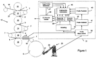
Figure 1 is a schematic representation of a diagram of reel building arrangement incorporating a method and apparatus for controlling at least one actuator affecting reel runnability; -
Figure 2 is a schematic representation of a multivariable CD (MVCD) control system in the arrangement ofFigure 1 ; -
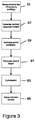
Figure 3 is a simplified flowchart showing a method of controlling at least one actuator in the system ofFigure 1 ; -
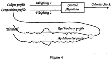
Figure 4 is a schematic representation of multivariable control target block in the arrangement ofFigure 1 ; and -
Figure 5 , comprisingFigures 5A and 5B , are graphs showing exemplary control weightings for use in the multivariable control target block ofFigure 4 . - Turning to
Figure 1 amulti-nip calender 10 is shown comprising sixrolls nips topmost nip 1 of the calender, which is disposed between thetopmost rolls upper roll 11 may, for example, be advantageously covered with a resilient surface, such as polymer, while thelower roll 12 may be a smooth-surface press roll, such as a metal roll. - An
induction heating system 21 generates magnetic flux that creates eddy currents for heating the surface of thecalender roll 12 to a high surface temperature, thereby providing local non-contact heating of themetal roll 12 for better gloss, increased nip load and improved caliper and hardness. - From the
topmost nip 1, the web W runs over aturning roll 7 into the second calendaringnip 2, which is formed between the heated smooth-surface press roll 12 and a roll 13 covered with a resilient cover, such as a polymer roll. - The web W then passes from the
second nip 2 around the roll 13 and thence to a third nip 3. The web W runs from the third nip 3 over aturning roll 7 into the fourth calendaring nip 4, which is formed, like thefirst nip 1, advantageously between a smooth-surface press roll 15, such as a metal roll, which is the lower roll of the fourth nip 4, and aroll 14 covered with a resilient cover, such as a polymer roll, which is the upper roll of the fourth nip 4. - From the fourth nip 4 the web W runs again over a
turning roll 7 into thefifth calendaring nip 5, which is formed, like the second calendaringnip 2, advantageously between a smooth-surface press roll 15, such as a metal roll, which is the upper roll of thefifth nip 5, and aroll 16 covered with a resilient cover, such as a polymer roll, which is the lower roll of thefifth nip 5. - According to an exemplary embodiment, any one or more of the rolls 11 - 16 may be zone-controlled rolls for providing profiling capabilities (i.e. multiple zone-controlled adjustment of diameter by small amounts (typically 0.5 - 1.0 mm) in cross direction), as is known in the art.
- After the
fifth nip 5, the web W is arranged to run through a thickness (caliper) measuring unit 8 and thence around alast turning roll 7 on to a reel-up/winder orspoof 9. A reel diameter andhardness measuring unit 25 includes ameasurement wheel 27 connected via anarm 29 to a pedestal or base.Unit 25 measures hardness measurement according to conventional methodology known in the art as the Backtender's Friend, for sensing cross-direction reel hardness via a piezo-electric crystal embedded in the rotatingwheel 27. However, in addition to the conventional piezo-electric crystal,measurement unit 25 also includes a second piezo-electric crystal that measures the contact pressure applied by themeasurement wheel 27 against the building paper reel on thespool 9. The measurement of hardness can therefore be taken independently of applied pressure as the reel is building. This is accomplished using a mathematical formula that includes reel diameter. As the reel builds, the angular position of theloading arm 29 changes. Theloading arm 29 is therefore equipped with a rotation transducer to indicate the angular position of thewheel 27 and the diameter of the building reel as the sensor traverses from edge to edge of the web W. - A multivariable CD (MVCD)
control system 31 is arranged in connection with themulti-nip calender 10 for controlling reel building and roll runnability as the web W winds on to spool 9, via a control feedback loop between actuators, such as the induction heater 21 (and/or zone-controlled rolls), and measurement units, such asunits 8 and 25. The results of measurements fromunits 8 and 25 are processed by theMVCD control system 31 for providing control action outputs for controllingactuators 21, etc. The non-limiting embodiment shows only a single actuator (induction heater) 21 being controlled by theMVCD control system 31, although in practice numerous actuators may be controlled. Similarly, the embodiment ofFigure 1 shows only twoprofile measurement units 8 and 25 whereas additional measurement units may be included (e.g. moisture detection, local tension variability (LTV), etc.) - Before further describing the non-limiting exemplary embodiment of
MVCD control system 31 inFigure 1 , a brief description of multivariable CD control will be provided. - A single variable CD process model typically includes: CD actuator to measurement profile mapping, CD actuator response shape and time domain dynamics. Mapping relates the position of actuators to the position of databoxes in the measurement profile, where a "databox" is an array element in the measurement profile representing a specific measurement value at a particular CD position. The CD actuator response shape represents the change in measurement profile when only a single actuator is moved while other actuators are maintained at their "pre-bump" state. The response shape so determined is the static transfer function in space. CD actuator time domain dynamics refers to the machine direction (MD) development of the response in time. It is generally assumed to be linear, as well as time and space invariant.
- A simple first order time domain model consists of time delay, response gain and time constant. This model can be expressed using the concept of a response matrix in the following format: ΔPl (t) = Rl ·ΔUl (t), wherein ΔPl(t) is an n-element vector representing an n cell measurement profile error from its target, ΔUl(t) is an m-element vector representing an m cell CD actuator control action, and Rl = Gl (q -1)·Al represents a CD model, where the polynomial Gl(q-1) is the dynamic part of the model. For the first order model, the dynamic part contains time delay and time constant information. The n by m response matrix Al is composed using the CD process mapping and CD actuator response shape and gain.
- For multivariable CD control, models from several CD actuators to a number of paper quality profiles need to be considered. The following model can therefore be used for a multivariable CD process with M actuators and N profiles, which is essentially a dimension expansion of conventional single-variable CD control:


- In the foregoing equation, ΔU is a one-dimensional vector representing M CD actuator control actions; ΔP is a one-dimensional vector representing N measurement profile errors. Different actuator and measurement profiles can have different resolutions. Each element of the response matrix R contains a CD model associated with the corresponding actuator and measurement profile, which includes the time domain, CD actuator response and mapping.
- With reference to
Figures 1 - 3 , upon collection of CD actuator excitation and profile responses via the profile measurement block 33 (step 55 inFigure 3 ), amodeling algorithm 35 generates CD nominal response models (step 57) viadynamic mapping block 37 andresponse generation block 39, set forth in greater detail in Nuyan et al, referred to above. - The determination CD property profile at
step 55 may be via measurement, calculation (or both), and the CD property profiles may include density (calculated from measurements of weight and thickness), stiffness (calculated from measurements of diameter and hardness), caliper profile, reel hardness profile, reel diameter profile, a composite of reel hardness profile and reel diameter profile, as discussed in greater detail below, or other. - A
profile validation block 41 excludes any abnormal profiles that may cause extreme control actions - A profile prediction or CD
control simulation block 43 operates in connection with the coremultivariable optimization block 45 and a targetprofile generation block 47 to process the measured cross-directional property profiles (e.g. hardness, reel diameter, calliper, etc.), calculate future profile error (step 59 inFigure 3 ) and control targets (step 61 inFigure 3 ), and perform multivariable control optimization (step 63) using the generated nominal profile models for generating control outputs (e.g. to zone-controlled rolls,induction heating system 21, etc.) of thecalender stack 10 via CD actuator handler 49 (step 65 ofFigure 3 ). - More particularly, as shown in
Figure 2 , amultivariable process model 51 is generated by themodelling block 35,response generation block 39 anddynamic mapping block 37. Themodel 51 is illustrated as a two-dimensional matrix representing a 3x3 CD process where the respective rows represents different profiles (e.g. hardness, calliper, etc.) and the columns represent different actuators in themulti-nip calender 10. The highlighted box (G23(q-1)) shows the CD response (z-axis) for a single actuator, where the x-axis represents the CD direction and the y-axis represents the MD direction. - In relation to the process model discussed above, ΔP(t) = [G(q -1)F(A)]ΔU(t), the predicted error ΔP(t) calculated by
profile prediction block 43 is indicated by e(i) inFigure 2 , the calender stack control output (out) ofmultivariable optimization block 45 is represented by successive control actions ΔU(t), and themodel transfer function 51, G(q -1)F(A), is output frommodeling algorithm 35,dynamic mapping block 37 andresponse generation block 39. Optimization of the controlled action is effected by minimizing the error e(i) between the target profile (sp) output from targetprofile generation block 47 and the predicted CV (mepr), within predefined actuator constraints for a prediction time period between hmin and hmax, where hmin is the minimum prediction horizon and hmax is the maximum prediction horizon. - According to an exemplary embodiment, weightings may be applied by the target
profile generation block 47 to different profiles, as shown inFigures 4 and5 . Thus, different weightings may be applied to respective ones of a first plurality of profiles input tooptimization block 45 based on a further property or a measure of dispersion of a further property. - According to another exemplary embodiment, two or more of the profiles may be combined to create a composite profile for application to the
optimization block 45. Moreover, it is contemplated that the dynamic weighting of cross-directional property profiles may be controlled by a further property or a measure of dispersion of a further property. For example, in a highly calendered application it may be desirable to create a composite profile from the reel hardness and reel diameter profiles and provide dynamic weightings to the caliper profile (Weighting 1) and composite profile (Weighting 2) based on the average reel diameter. This is because the diameter of the building reel will affect the influence of respective profiles on the desired control action. Specifically, at the start of the reel building process (when the reel diameter is small), it is desirable that the caliper profile have a higher weighting than the composite whereas at large reel diameters the combined reel hardness and reel diameter profiles should be emphasized in the optimization process, as shown inFigures 5A and 5B , wherein f(R) is the varying weighting as a function of reel diameter and f(σ) is the varying weighting as a function of one of either base sheet moisture or weight variability. - The cross-directional property profile(s) may be selected based on a function of one of either a specific process or specific reel condition, such as a measured reel property (caliper, reel diameter, reel hardness, etc.) The specific process comprises the specific reel condition plus a function of a base sheet property, such as weight profile, tension profile and moisture profile. The selection function may, for example, be a measure of dispersion of a further property or may be a function such as average reel diameter. Where the function is a measure of dispersion, that measure may, for example, be one of variance, standard deviation (σ), multiples of standard deviations, coefficients of variation, etc.
- Specific embodiments have been shown and described herein. However, modifications and variations may occur to those skilled in the art. For example, although the exemplary embodiment of
Figure 1 refers to measuring caliper, reel diameter and reel hardness, other measured cross-directional property profiles are possible, such as tension (pre-wound tension or wound-in tension). Also, although the exemplary embodiment ofFigure 4 shows two cross-directional property profiles, it is entirely possible that three or more profiles may be combined. Furthermore, although the two cross-directional property profiles shown inFigure 4 are caliper profile and a composite of reel hardness profile and reel diameter profile, it is contemplated that the two cross-directional property profiles may be caliper profile and only one of reel hardness profile and reel diameter profile. In addition, whereas the dynamic weighting of cross-directional property profiles is discussed above as being controlled by average reel diameter, it is contemplated that the controlling further property may be a function of weight or tension. Moreover, although the described embodiments set forth a multivariable optimization process, it is contemplated that a single variable solution may be provided using only one controlled variable and means of target generation and/or response generation. - All such modifications and variations are believed to be within the sphere and scope of the present embodiment.
Claims (9)
- A method for controlling at least one array of M cross-directional actuators in a moving web manufacturing process, comprising:determining N sets of cross-directional property profiles from at least two at different locations on said moving web and generating an N x M array of nominal responses, according to
 generating a set of multivariable profile predictions calculated from said nominal responses to said cross-directional property profiles;generating a set of multivariable control targets based on said plurality of cross-directional property profiles; andadjusting control of said at least one array of M cross-directional actuators by minimizing error between said set of multivariable control targets and said set of multivariable profile predictions, wherein different ones of said profiles have different resolutions and individual mapping arrays to each of the actuator arrays.
 - The method according to claim 1, wherein said determining comprises one of either measuring and/or calculating at least one of said plurality of cross-directional property profiles.
- The method according to claim 2, wherein said at least one of said plurality of cross-directional property profiles is density, and wherein density is calculated from measurements of weight and thickness, and/or
wherein said at least one of said plurality of cross-directional property profiles is stiffness, and wherein stiffness is calculated from measurements of diameter and hardness, and/or
wherein said at least one of said plurality of cross-directional property profiles is measured tension. - The method according to claim 3, wherein said measured tension is one of either pre-wound tension or wound-in tension.
- The method according to claim 1, wherein said multivariable control target is generated based on dynamic weighting of said plurality of cross-directional property profiles.
- The method according to claim 5, wherein said dynamic weighting of at least two of said cross-directional property profiles may be controlled by a measure of dispersion of a further property.
- The method according to claim 6, wherein said at least two cross-directional property profiles are caliper profile and one of reel hardness profile and reel diameter profile, and/or
wherein said at least two cross-directional property profiles are caliper profile and a composite of reel hardness profile and reel diameter profile, and/or
wherein said further property is at least one of average reel diameter, weight, and caliper, and/or
wherein said measure of dispersion is one of variance, standard deviation (σ), multiples of standard deviations, or coefficient of variation. - The method according to claim 1, wherein at least one of said cross-directional property profiles is selected from the group consisting of reel diameter, caliper, hardness and tension.
- A system for controlling at least one array of M cross-directional actuators in a moving web manufacturing process, comprising:means for determining N sets of cross-directional property profiles from at least two at different locations on said moving web and generating an N x M array of nominal responses, according to
 means for generating a set of multivariable profile predictions calculated from said nominal responses to said cross-directional property profiles;means for generating a set of multivariable control targets based on said plurality of cross-directional property profiles; andmeans for adjusting control of said at least one array of M cross-directional actuators by minimizing error between said set of multivariable control targets and said set of multivariable profile predictions, wherein different ones of said profiles have different resolutions and individual mapping arrays to each of the actuator arrays.
Applications Claiming Priority (1)
| Application Number | Priority Date | Filing Date | Title |
|---|---|---|---|
| PCT/US2008/007319 WO2009151419A1 (en) | 2008-06-12 | 2008-06-12 | Method and apparatus for reel building and roll runnability in moving web manufacturing |
Publications (3)
| Publication Number | Publication Date |
|---|---|
| EP2297618A1 EP2297618A1 (en) | 2011-03-23 |
| EP2297618A4 EP2297618A4 (en) | 2012-02-15 |
| EP2297618B1 true EP2297618B1 (en) | 2019-12-11 |
Family
ID=41416954
Family Applications (1)
| Application Number | Title | Priority Date | Filing Date |
|---|---|---|---|
| EP08768372.8A Active EP2297618B1 (en) | 2008-06-12 | 2008-06-12 | Method and apparatus for reel building and roll runnability in moving web manufacturing |
Country Status (5)
| Country | Link |
|---|---|
| US (1) | US8489221B2 (en) |
| EP (1) | EP2297618B1 (en) |
| CN (1) | CN102099754B (en) |
| CA (1) | CA2727396C (en) |
| WO (1) | WO2009151419A1 (en) |
Families Citing this family (11)
| Publication number | Priority date | Publication date | Assignee | Title |
|---|---|---|---|---|
| US9069345B2 (en) | 2009-01-23 | 2015-06-30 | Mks Instruments, Inc. | Controlling a manufacturing process with a multivariate model |
| US9481777B2 (en) | 2012-03-30 | 2016-11-01 | The Procter & Gamble Company | Method of dewatering in a continuous high internal phase emulsion foam forming process |
| US9541471B2 (en) | 2012-04-06 | 2017-01-10 | Mks Instruments, Inc. | Multivariate prediction of a batch manufacturing process |
| US9429939B2 (en) | 2012-04-06 | 2016-08-30 | Mks Instruments, Inc. | Multivariate monitoring of a batch manufacturing process |
| DE102012110790B4 (en) * | 2012-11-09 | 2017-04-27 | Windmöller & Hölscher Kg | Method for determining the winding quality of a film roll |
| WO2015037165A1 (en) * | 2013-09-12 | 2015-03-19 | 日本電気株式会社 | Information processing device, predictive control method, and recording medium |
| WO2016061607A1 (en) * | 2014-10-24 | 2016-04-28 | Berndorf Band Gmbh | Process optimisation for a strip casting system |
| MX2020010428A (en) * | 2018-04-04 | 2020-10-28 | Paper Converting Machine Co | Control for parent roll unwinding apparatus and methods. |
| IT201800006680A1 (en) * | 2018-06-26 | 2019-12-26 | METHOD FOR PREDICTING THE PRESENCE OF PRODUCT DEFECTS DURING AN INTERMEDIATE PROCESSING PHASE OF A THIN PRODUCT WRAPPED IN COIL | |
| JP7024752B2 (en) * | 2019-03-20 | 2022-02-24 | オムロン株式会社 | Control system and control program |
| US20210403266A1 (en) * | 2020-06-26 | 2021-12-30 | Paper Converting Machine Company | Method for Producing Coreless Roll Products |
Family Cites Families (8)
| Publication number | Priority date | Publication date | Assignee | Title |
|---|---|---|---|---|
| US3936665A (en) * | 1972-06-12 | 1976-02-03 | Industrial Nucleonics Corporation | Sheet material characteristic measuring, monitoring and controlling method and apparatus using data profile generated and evaluated by computer means |
| US6284100B1 (en) * | 1997-01-24 | 2001-09-04 | Valmet Corporation | Method and apparatus for controlling a headbox in a paper machine |
| US6343240B1 (en) * | 1997-12-29 | 2002-01-29 | Neles Paper Automation Oy | Method for identifying plural relations in a sheet manufacturing process |
| US6421575B1 (en) | 1999-12-01 | 2002-07-16 | Metso Paper Automation Oy | Method and control arrangement for controlling sheet-making process |
| FI120053B (en) * | 2000-12-22 | 2009-06-15 | Metso Automation Oy | Method and apparatus for adjusting the moisture profile of a moving paper web |
| JP2008504545A (en) * | 2004-07-01 | 2008-02-14 | メッツォ ペーパー インコーポレイテッド | Reeling method, system and measuring device |
| US20060254367A1 (en) * | 2005-05-12 | 2006-11-16 | Abb Ltd. | Measurement system for improved paper roll runnability |
| US7454253B2 (en) * | 2006-03-30 | 2008-11-18 | Honeywell Asca Inc. | Fast performance prediction of multivariable model predictive controller for paper machine cross-directional processes |
-
2008
- 2008-06-12 CN CN200880130440.1A patent/CN102099754B/en active Active
- 2008-06-12 US US12/996,798 patent/US8489221B2/en active Active
- 2008-06-12 EP EP08768372.8A patent/EP2297618B1/en active Active
- 2008-06-12 WO PCT/US2008/007319 patent/WO2009151419A1/en active Application Filing
- 2008-06-12 CA CA2727396A patent/CA2727396C/en active Active
Non-Patent Citations (1)
| Title |
|---|
| None * |
Also Published As
| Publication number | Publication date |
|---|---|
| US20110264254A1 (en) | 2011-10-27 |
| CA2727396A1 (en) | 2009-12-17 |
| US8489221B2 (en) | 2013-07-16 |
| CA2727396C (en) | 2015-12-01 |
| CN102099754B (en) | 2016-05-11 |
| EP2297618A4 (en) | 2012-02-15 |
| WO2009151419A1 (en) | 2009-12-17 |
| EP2297618A1 (en) | 2011-03-23 |
| CN102099754A (en) | 2011-06-15 |
Similar Documents
| Publication | Publication Date | Title |
|---|---|---|
| EP2297618B1 (en) | Method and apparatus for reel building and roll runnability in moving web manufacturing | |
| EP1888839B1 (en) | Measurement system for improved paper roll winding | |
| EP2013668B1 (en) | Apparatus and method for coordinating controllers to control a paper machine or other machine | |
| US6807510B1 (en) | Model predictive controller for coordinated cross direction and machine direction control | |
| US8600525B1 (en) | Efficient quadratic programming (QP) solver for process control and optimization | |
| US7185537B2 (en) | Nip and loading analysis system | |
| EP2572038B1 (en) | Apparatus and method for controlling curling potential of paper, paperboard, or other product during manufacture | |
| CA2647716A1 (en) | Fast performance prediction of multivariable model predictive controller for paper machine cross-directional processes | |
| VanAntwerp et al. | Cross-directional control of sheet and film processes | |
| JP2008504545A (en) | Reeling method, system and measuring device | |
| US11634293B2 (en) | Adaptive sheet caliper control system and apparatus and methods | |
| US20160378073A1 (en) | Layered approach to economic optimization and model-based control of paper machines and other systems | |
| US6584366B1 (en) | Method and arrangement for neural modeling of a paper winding device | |
| JP2006526714A (en) | Modeling, prediction and control of paper curl and twist based on partial least squares | |
| US20060011766A1 (en) | Method for controlling a wind-up, including determining running parameters based on models taking un-winding into account | |
| Parent et al. | A guide to eliminating baggy webs | |
| Parent et al. | Bagginess and baggy streaks: A novel measurement technique to quantify tension profile of a web in cross-direction at high resolution | |
| JP2001133242A (en) | Thickness measuring apparatus | |
| JPH0726491A (en) | Control unit for thickness profile of calender and calendering method |
Legal Events
| Date | Code | Title | Description |
|---|---|---|---|
| PUAI | Public reference made under article 153(3) epc to a published international application that has entered the european phase |
Free format text: ORIGINAL CODE: 0009012 |
|
| 17P | Request for examination filed |
Effective date: 20101209 |
|
| AK | Designated contracting states |
Kind code of ref document: A1 Designated state(s): AT BE BG CH CY CZ DE DK EE ES FI FR GB GR HR HU IE IS IT LI LT LU LV MC MT NL NO PL PT RO SE SI SK TR |
|
| AX | Request for extension of the european patent |
Extension state: AL BA MK RS |
|
| DAX | Request for extension of the european patent (deleted) | ||
| A4 | Supplementary search report drawn up and despatched |
Effective date: 20120118 |
|
| RIC1 | Information provided on ipc code assigned before grant |
Ipc: B65H 23/00 20060101ALI20120112BHEP Ipc: D21G 9/00 20060101ALI20120112BHEP Ipc: G05B 13/04 20060101AFI20120112BHEP Ipc: G05B 11/32 20060101ALI20120112BHEP |
|
| RAP1 | Party data changed (applicant data changed or rights of an application transferred) |
Owner name: VALMET AUTOMATION, INC. |
|
| STAA | Information on the status of an ep patent application or granted ep patent |
Free format text: STATUS: EXAMINATION IS IN PROGRESS |
|
| 17Q | First examination report despatched |
Effective date: 20180612 |
|
| GRAP | Despatch of communication of intention to grant a patent |
Free format text: ORIGINAL CODE: EPIDOSNIGR1 |
|
| STAA | Information on the status of an ep patent application or granted ep patent |
Free format text: STATUS: GRANT OF PATENT IS INTENDED |
|
| INTG | Intention to grant announced |
Effective date: 20190702 |
|
| GRAS | Grant fee paid |
Free format text: ORIGINAL CODE: EPIDOSNIGR3 |
|
| GRAA | (expected) grant |
Free format text: ORIGINAL CODE: 0009210 |
|
| STAA | Information on the status of an ep patent application or granted ep patent |
Free format text: STATUS: THE PATENT HAS BEEN GRANTED |
|
| AK | Designated contracting states |
Kind code of ref document: B1 Designated state(s): AT BE BG CH CY CZ DE DK EE ES FI FR GB GR HR HU IE IS IT LI LT LU LV MC MT NL NO PL PT RO SE SI SK TR |
|
| REG | Reference to a national code |
Ref country code: GB Ref legal event code: FG4D |
|
| REG | Reference to a national code |
Ref country code: CH Ref legal event code: EP |
|
| REG | Reference to a national code |
Ref country code: AT Ref legal event code: REF Ref document number: 1212820 Country of ref document: AT Kind code of ref document: T Effective date: 20191215 |
|
| REG | Reference to a national code |
Ref country code: DE Ref legal event code: R096 Ref document number: 602008061809 Country of ref document: DE |
|
| REG | Reference to a national code |
Ref country code: IE Ref legal event code: FG4D |
|
| REG | Reference to a national code |
Ref country code: NL Ref legal event code: MP Effective date: 20191211 |
|
| REG | Reference to a national code |
Ref country code: LT Ref legal event code: MG4D |
|
| PG25 | Lapsed in a contracting state [announced via postgrant information from national office to epo] |
Ref country code: ES Free format text: LAPSE BECAUSE OF FAILURE TO SUBMIT A TRANSLATION OF THE DESCRIPTION OR TO PAY THE FEE WITHIN THE PRESCRIBED TIME-LIMIT Effective date: 20191211 Ref country code: SE Free format text: LAPSE BECAUSE OF FAILURE TO SUBMIT A TRANSLATION OF THE DESCRIPTION OR TO PAY THE FEE WITHIN THE PRESCRIBED TIME-LIMIT Effective date: 20191211 Ref country code: LV Free format text: LAPSE BECAUSE OF FAILURE TO SUBMIT A TRANSLATION OF THE DESCRIPTION OR TO PAY THE FEE WITHIN THE PRESCRIBED TIME-LIMIT Effective date: 20191211 Ref country code: GR Free format text: LAPSE BECAUSE OF FAILURE TO SUBMIT A TRANSLATION OF THE DESCRIPTION OR TO PAY THE FEE WITHIN THE PRESCRIBED TIME-LIMIT Effective date: 20200312 Ref country code: BG Free format text: LAPSE BECAUSE OF FAILURE TO SUBMIT A TRANSLATION OF THE DESCRIPTION OR TO PAY THE FEE WITHIN THE PRESCRIBED TIME-LIMIT Effective date: 20200311 Ref country code: LT Free format text: LAPSE BECAUSE OF FAILURE TO SUBMIT A TRANSLATION OF THE DESCRIPTION OR TO PAY THE FEE WITHIN THE PRESCRIBED TIME-LIMIT Effective date: 20191211 Ref country code: NO Free format text: LAPSE BECAUSE OF FAILURE TO SUBMIT A TRANSLATION OF THE DESCRIPTION OR TO PAY THE FEE WITHIN THE PRESCRIBED TIME-LIMIT Effective date: 20200311 Ref country code: FI Free format text: LAPSE BECAUSE OF FAILURE TO SUBMIT A TRANSLATION OF THE DESCRIPTION OR TO PAY THE FEE WITHIN THE PRESCRIBED TIME-LIMIT Effective date: 20191211 |
|
| PG25 | Lapsed in a contracting state [announced via postgrant information from national office to epo] |
Ref country code: HR Free format text: LAPSE BECAUSE OF FAILURE TO SUBMIT A TRANSLATION OF THE DESCRIPTION OR TO PAY THE FEE WITHIN THE PRESCRIBED TIME-LIMIT Effective date: 20191211 |
|
| PG25 | Lapsed in a contracting state [announced via postgrant information from national office to epo] |
Ref country code: RO Free format text: LAPSE BECAUSE OF FAILURE TO SUBMIT A TRANSLATION OF THE DESCRIPTION OR TO PAY THE FEE WITHIN THE PRESCRIBED TIME-LIMIT Effective date: 20191211 Ref country code: PT Free format text: LAPSE BECAUSE OF FAILURE TO SUBMIT A TRANSLATION OF THE DESCRIPTION OR TO PAY THE FEE WITHIN THE PRESCRIBED TIME-LIMIT Effective date: 20200506 Ref country code: CZ Free format text: LAPSE BECAUSE OF FAILURE TO SUBMIT A TRANSLATION OF THE DESCRIPTION OR TO PAY THE FEE WITHIN THE PRESCRIBED TIME-LIMIT Effective date: 20191211 Ref country code: NL Free format text: LAPSE BECAUSE OF FAILURE TO SUBMIT A TRANSLATION OF THE DESCRIPTION OR TO PAY THE FEE WITHIN THE PRESCRIBED TIME-LIMIT Effective date: 20191211 Ref country code: EE Free format text: LAPSE BECAUSE OF FAILURE TO SUBMIT A TRANSLATION OF THE DESCRIPTION OR TO PAY THE FEE WITHIN THE PRESCRIBED TIME-LIMIT Effective date: 20191211 |
|
| PG25 | Lapsed in a contracting state [announced via postgrant information from national office to epo] |
Ref country code: SK Free format text: LAPSE BECAUSE OF FAILURE TO SUBMIT A TRANSLATION OF THE DESCRIPTION OR TO PAY THE FEE WITHIN THE PRESCRIBED TIME-LIMIT Effective date: 20191211 Ref country code: IS Free format text: LAPSE BECAUSE OF FAILURE TO SUBMIT A TRANSLATION OF THE DESCRIPTION OR TO PAY THE FEE WITHIN THE PRESCRIBED TIME-LIMIT Effective date: 20200411 |
|
| REG | Reference to a national code |
Ref country code: DE Ref legal event code: R097 Ref document number: 602008061809 Country of ref document: DE |
|
| REG | Reference to a national code |
Ref country code: AT Ref legal event code: MK05 Ref document number: 1212820 Country of ref document: AT Kind code of ref document: T Effective date: 20191211 |
|
| PLBE | No opposition filed within time limit |
Free format text: ORIGINAL CODE: 0009261 |
|
| STAA | Information on the status of an ep patent application or granted ep patent |
Free format text: STATUS: NO OPPOSITION FILED WITHIN TIME LIMIT |
|
| PG25 | Lapsed in a contracting state [announced via postgrant information from national office to epo] |
Ref country code: DK Free format text: LAPSE BECAUSE OF FAILURE TO SUBMIT A TRANSLATION OF THE DESCRIPTION OR TO PAY THE FEE WITHIN THE PRESCRIBED TIME-LIMIT Effective date: 20191211 |
|
| 26N | No opposition filed |
Effective date: 20200914 |
|
| PG25 | Lapsed in a contracting state [announced via postgrant information from national office to epo] |
Ref country code: AT Free format text: LAPSE BECAUSE OF FAILURE TO SUBMIT A TRANSLATION OF THE DESCRIPTION OR TO PAY THE FEE WITHIN THE PRESCRIBED TIME-LIMIT Effective date: 20191211 Ref country code: PL Free format text: LAPSE BECAUSE OF FAILURE TO SUBMIT A TRANSLATION OF THE DESCRIPTION OR TO PAY THE FEE WITHIN THE PRESCRIBED TIME-LIMIT Effective date: 20191211 Ref country code: SI Free format text: LAPSE BECAUSE OF FAILURE TO SUBMIT A TRANSLATION OF THE DESCRIPTION OR TO PAY THE FEE WITHIN THE PRESCRIBED TIME-LIMIT Effective date: 20191211 |
|
| PG25 | Lapsed in a contracting state [announced via postgrant information from national office to epo] |
Ref country code: IT Free format text: LAPSE BECAUSE OF FAILURE TO SUBMIT A TRANSLATION OF THE DESCRIPTION OR TO PAY THE FEE WITHIN THE PRESCRIBED TIME-LIMIT Effective date: 20191211 Ref country code: MC Free format text: LAPSE BECAUSE OF FAILURE TO SUBMIT A TRANSLATION OF THE DESCRIPTION OR TO PAY THE FEE WITHIN THE PRESCRIBED TIME-LIMIT Effective date: 20191211 |
|
| REG | Reference to a national code |
Ref country code: CH Ref legal event code: PL |
|
| GBPC | Gb: european patent ceased through non-payment of renewal fee |
Effective date: 20200612 |
|
| PG25 | Lapsed in a contracting state [announced via postgrant information from national office to epo] |
Ref country code: LU Free format text: LAPSE BECAUSE OF NON-PAYMENT OF DUE FEES Effective date: 20200612 |
|
| REG | Reference to a national code |
Ref country code: BE Ref legal event code: MM Effective date: 20200630 |
|
| PG25 | Lapsed in a contracting state [announced via postgrant information from national office to epo] |
Ref country code: GB Free format text: LAPSE BECAUSE OF NON-PAYMENT OF DUE FEES Effective date: 20200612 Ref country code: FR Free format text: LAPSE BECAUSE OF NON-PAYMENT OF DUE FEES Effective date: 20200630 Ref country code: CH Free format text: LAPSE BECAUSE OF NON-PAYMENT OF DUE FEES Effective date: 20200630 Ref country code: IE Free format text: LAPSE BECAUSE OF NON-PAYMENT OF DUE FEES Effective date: 20200612 Ref country code: LI Free format text: LAPSE BECAUSE OF NON-PAYMENT OF DUE FEES Effective date: 20200630 |
|
| PG25 | Lapsed in a contracting state [announced via postgrant information from national office to epo] |
Ref country code: BE Free format text: LAPSE BECAUSE OF NON-PAYMENT OF DUE FEES Effective date: 20200630 |
|
| PG25 | Lapsed in a contracting state [announced via postgrant information from national office to epo] |
Ref country code: TR Free format text: LAPSE BECAUSE OF FAILURE TO SUBMIT A TRANSLATION OF THE DESCRIPTION OR TO PAY THE FEE WITHIN THE PRESCRIBED TIME-LIMIT Effective date: 20191211 Ref country code: MT Free format text: LAPSE BECAUSE OF FAILURE TO SUBMIT A TRANSLATION OF THE DESCRIPTION OR TO PAY THE FEE WITHIN THE PRESCRIBED TIME-LIMIT Effective date: 20191211 Ref country code: CY Free format text: LAPSE BECAUSE OF FAILURE TO SUBMIT A TRANSLATION OF THE DESCRIPTION OR TO PAY THE FEE WITHIN THE PRESCRIBED TIME-LIMIT Effective date: 20191211 |
|
| PGFP | Annual fee paid to national office [announced via postgrant information from national office to epo] |
Ref country code: DE Payment date: 20220620 Year of fee payment: 15 |
|
| REG | Reference to a national code |
Ref country code: DE Ref legal event code: R119 Ref document number: 602008061809 Country of ref document: DE |