EP2296978B1 - Device for concentration measurements and sterilization chamber and filling machine comprising said device - Google Patents
Device for concentration measurements and sterilization chamber and filling machine comprising said device Download PDFInfo
- Publication number
- EP2296978B1 EP2296978B1 EP09798202.9A EP09798202A EP2296978B1 EP 2296978 B1 EP2296978 B1 EP 2296978B1 EP 09798202 A EP09798202 A EP 09798202A EP 2296978 B1 EP2296978 B1 EP 2296978B1
- Authority
- EP
- European Patent Office
- Prior art keywords
- catalyst
- inlet
- concentration
- thermometer
- housing
- Prior art date
- Legal status (The legal status is an assumption and is not a legal conclusion. Google has not performed a legal analysis and makes no representation as to the accuracy of the status listed.)
- Active
Links
Images

Classifications
-
- B—PERFORMING OPERATIONS; TRANSPORTING
- B65—CONVEYING; PACKING; STORING; HANDLING THIN OR FILAMENTARY MATERIAL
- B65B—MACHINES, APPARATUS OR DEVICES FOR, OR METHODS OF, PACKAGING ARTICLES OR MATERIALS; UNPACKING
- B65B55/00—Preserving, protecting or purifying packages or package contents in association with packaging
- B65B55/02—Sterilising, e.g. of complete packages
- B65B55/04—Sterilising wrappers or receptacles prior to, or during, packaging
- B65B55/10—Sterilising wrappers or receptacles prior to, or during, packaging by liquids or gases
- B65B55/103—Sterilising flat or tubular webs
-
- G—PHYSICS
- G01—MEASURING; TESTING
- G01N—INVESTIGATING OR ANALYSING MATERIALS BY DETERMINING THEIR CHEMICAL OR PHYSICAL PROPERTIES
- G01N25/00—Investigating or analyzing materials by the use of thermal means
- G01N25/20—Investigating or analyzing materials by the use of thermal means by investigating the development of heat, i.e. calorimetry, e.g. by measuring specific heat, by measuring thermal conductivity
- G01N25/22—Investigating or analyzing materials by the use of thermal means by investigating the development of heat, i.e. calorimetry, e.g. by measuring specific heat, by measuring thermal conductivity on combustion or catalytic oxidation, e.g. of components of gas mixtures
- G01N25/40—Investigating or analyzing materials by the use of thermal means by investigating the development of heat, i.e. calorimetry, e.g. by measuring specific heat, by measuring thermal conductivity on combustion or catalytic oxidation, e.g. of components of gas mixtures the heat developed being transferred to a flowing fluid
- G01N25/42—Investigating or analyzing materials by the use of thermal means by investigating the development of heat, i.e. calorimetry, e.g. by measuring specific heat, by measuring thermal conductivity on combustion or catalytic oxidation, e.g. of components of gas mixtures the heat developed being transferred to a flowing fluid continuously
-
- A—HUMAN NECESSITIES
- A61—MEDICAL OR VETERINARY SCIENCE; HYGIENE
- A61L—METHODS OR APPARATUS FOR STERILISING MATERIALS OR OBJECTS IN GENERAL; DISINFECTION, STERILISATION OR DEODORISATION OF AIR; CHEMICAL ASPECTS OF BANDAGES, DRESSINGS, ABSORBENT PADS OR SURGICAL ARTICLES; MATERIALS FOR BANDAGES, DRESSINGS, ABSORBENT PADS OR SURGICAL ARTICLES
- A61L2/00—Disinfection or sterilisation of materials or objects, in general; Accessories therefor
- A61L2/26—Accessories
-
- B—PERFORMING OPERATIONS; TRANSPORTING
- B65—CONVEYING; PACKING; STORING; HANDLING THIN OR FILAMENTARY MATERIAL
- B65B—MACHINES, APPARATUS OR DEVICES FOR, OR METHODS OF, PACKAGING ARTICLES OR MATERIALS; UNPACKING
- B65B9/00—Enclosing successive articles, or quantities of material, e.g. liquids or semiliquids, in flat, folded, or tubular webs of flexible sheet material; Subdividing filled flexible tubes to form packages
- B65B9/10—Enclosing successive articles, or quantities of material, in preformed tubular webs, or in webs formed into tubes around filling nozzles, e.g. extruded tubular webs
- B65B9/20—Enclosing successive articles, or quantities of material, in preformed tubular webs, or in webs formed into tubes around filling nozzles, e.g. extruded tubular webs the webs being formed into tubes in situ around the filling nozzles
Definitions
- the present invention relates to a device for concentration measurements, and a sterilization chamber of a filling machine for producing food packages.
- the invention also relates to a machine for producing packages comprising such a device.
- packages intended for liquid food are often produced from a packaging laminate comprising a core layer of paper or paperboard and an outer, liquid-tight layer of thermoplastic material on at least that side of the core layer which will form the inside of the packages.
- the packaging laminate usually further comprises a layer of a gas barrier material. This layer is in most cases an aluminum foil which also enables induction sealing of the packaging laminate.
- the packages are often produced in a packaging machine where a web of packaging laminate is formed into a tube which is closed by sealing of the longitudinal edges of the web in an overlapping condition.
- the longitudinally sealed tube is continuously filled with a product and then transversally sealed, wherein filled "cushions" are formed.
- the transverse sealing is made along narrow, transverse, mutually spaced apart, sealing zones. After the transverse sealing, the "cushions" are separated from the rest of the tube by incisions in the sealing zones and finally formed into the desired shape.
- carton bottles are frequently occurring packages.
- these are composed of a lower part in the form of a sleeve of packaging laminate like the one described above, and an upper part in the form of a plastic top provided with an opening device, such as a cap.
- the carton bottles are often produced in a packaging machine where sheets, so-called blanks, of packaging laminate are formed into tubes which are closed by sealing of two opposing edges of each sheet in an overlapping condition. Then, each tube is slipped over a respective plastic top and arranged in such a way that a major part of the plastic top protrudes from the tube. After sealing of the top and the tube along a contact surface between them, the package is filled, sealed at the open end of the tube for achieving a sleeve and closing the package, and finally formed into the desired shape.
- a known way of sterilizing packaging material is chemical sterilization.
- chemical sterilization can be made by passing the packaging material through a bath of hydrogen peroxide solution and then through a heating chamber. In the heating chamber, hot sterile air is introduced for heating the packaging material to such a degree that the hydrogen peroxide is evaporated and thus removed from the surface of the packaging material.
- the above method works excellent when it comes to sterilization of a continuous web of packaging laminate but is obviously less suited for sterilization of open carton bottles prior to filling.
- gas phase sterilization can instead be used.
- Such sterilization can be made by passing the carton bottles through a preheating chamber for preheating, a gassing chamber containing gaseous hydrogen peroxide and then through a venting chamber. In the venting chamber, the carton bottles are exposed to a flow of hot sterile air for removal of residues of hydrogen peroxide.
- a gas phase sterilization device adapted for sterilization of carton bottles is known from the Swedish patent number 0203692-9 .
- the concentration is too low, the hydrogen peroxide applied onto the packaging material evaporates too quickly resulting in a risk of insufficient sterilization.
- the concentration is too high, the hydrogen peroxide applied onto the packaging material evaporates too slowly resulting in a risk of unallowable peroxide residues on the packaging material leaving the heating chamber.
- accurate control of the hydrogen peroxide concentration in the gas mixture inside the gassing chamber is crucial. If the concentration is too low, there is a risk of insufficient sterilization.
- the concentration is too high, there is a risk of too much peroxide on the carton bottles leaving the gassing chamber and, consequently, a risk of unallowable peroxide residues on the carton bottles leaving the venting chamber. In either case, if the peroxide concentration is not within certain limits, the settings of the packaging machine should be changed.
- the hydrogen peroxide concentration in the gas mixture inside the heating chamber is estimated by the machine control system based on the concentration of hydrogen peroxide in the solution, the consumption of hydrogen peroxide solution and the air mass flow inside the heating chamber.
- the hydrogen peroxide concentration is theoretically calculated from known external parameters. This is a somewhat uncertain determination method and it involves a risk of erroneous concentration determinations and, thus, a risk of false alarms, or the packaging material being insufficiently sterilized or too high levels of residual hydrogen peroxide being left on the packaging material.
- the hydrogen peroxide concentration in the gas mixture inside the gassing chamber is measured by means of IR-sensors or UV-sensors.
- IR-sensors or UV-sensors are bulky, fragile and cost a lot of money.
- a related device for measuring a concentration of hydrogen peroxide is disclosed in WO 2008/088248 .
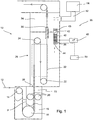
- a machine 10 working in accordance with a predetermined process for producing packages from a tube (not shown) of packaging laminate is shown.
- the packaging laminate is of the initially described kind, i.e. it comprises a paper core layer, an aluminum gas barrier layer and outer layers of thermoplastic material, and similar kinds of packaging material are also possible, e.g. with additional layers or without an aluminum layer.
- the tube is formed by sealing of the longitudinal edges of a web 12 of packaging laminate in an overlapping condition. After forming, the tube is filled with the intended product and transversally sealed at regular intervals. The “cushions" thus formed are separated from the rest of the tube and finally formed into the desired shape. Continuous forming, filling and sealing of a tube like this is well-known and will not be described in detail herein.
- the web 12 of packaging laminate Prior to tube forming, the web 12 of packaging laminate is sterilized. To this end, the web 12 is directed, by means of directing rollers 14 and 16, through a bath 18 containing a hydrogen peroxide solution.
- the bath can be of any of the types described in applicant's Chinese patent applications number 200510069635.8 and 200510133873.0 .
- the web 12 After leaving the bath 18, the web 12 is passed between two squeegee rollers 20 for evenly spreading out the peroxide solution over the entire width of the web 12 and removing excess peroxide.
- the web 12, now carrying droplets of hydrogen peroxide solution is directed, by means of directing rollers 22, 24, through a heating chamber 26 for further hydrogen peroxide removal by evaporation.
- the web 12 enters the heating chamber 26 through an entrance opening 28 and exits the same through an exit opening 30.
- the sterilization or heating chamber 26 comprises a heating arrangement, schematically illustrated by the box with dashed lines and denoted 32 in Fig. 1 , for effecting the evaporation of the hydrogen peroxide solution applied onto the web 12.
- the heating arrangement 32 which, for example, can be of the type described in applicant's Chinese patent application number 200510069630.5 , is arranged to introduce hot sterile air into the heating chamber.
- hot air is meant air of a temperature that is high enough to perform the evaporation of the sterilization agent used, here hydrogen peroxide.
- the heating arrangement thus comprises means for supplying air to the heating chamber 26, such as a fan or similar (not shown).
- the environment inside the heating chamber is carefully controlled. Specifically, it is desirable to frequently measure the hydrogen peroxide concentration in the gas mixture inside the heating chamber 26, which gas mixture consists of air and gaseous hydrogen peroxide evaporated from the web of packaging laminate when passing through the heating chamber 26.
- the hydrogen peroxide concentration inside the heating chamber is dependent upon a number of different parameters, such as the hydrogen peroxide concentration in the solution in the bath 18, the consumption of the solution in the bath and the flow of hot sterile air into the chamber. If the hydrogen peroxide concentration inside the heating chamber is too high, there is a risk of unallowable residues of hydrogen peroxide on the web when this leaves the heating chamber.
- the settings of the machine should preferably be adjusted.
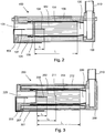
- the heating chamber 26 further has a device 36, 100, 200 for determining the concentration of hydrogen peroxide in the gas mixture inside the heating chamber 26, one embodiment 100 of said device is shown in detail in Fig. 2 .
- the device 100 comprises a housing 101 accommodating a measuring catalyst means or catalyst 102 in the form of a body of ceramic material dipped in precious metal solution, such as platinum solution.
- the catalytic body can have an outer shape of a rectangular parallelepiped. Channels with essentially square-shaped cross-sections running side by side in the longitudinal direction of rectangular parallelepiped fill up the entire interior of the catalyst 102. This structure gives the catalyst 102 a lattice-like cross-section in the transverse directions.
- a circular cross-section or similar of the catalyst body 102 is also possible, as well as channels therein having circular cross-sections or similar.
- the catalyst body 102 is in one embodiment manufactured by a material having good thermal conduction, such as a metal or similar. This reduces the temperature gradients in the x-direction and improves the reliability of the measurements.
- the catalyst 102 is surrounded by the housing 101, e.g. made of stainless steel or similar.
- a first end piece 103 is mounted at the upstream end of the housing 101.
- This first end piece 103 is in one embodiment manufactured of an insulating material, such as a polymer or similar.
- the catalyst 102 is in Fig. 2 fixed to the first end piece 103 by a shrink hose 104, which encompasses the catalyst body 102 and ends at the outlet of the catalyst body.
- the shrink hose 104 separates surrounding insulation 105 from being in contact with the catalyst body 102, and also allows the catalyst body 102 to be fixed at a certain distance from the first end piece 103.
- the housing 101 is at a downstream end attached to a second end piece 106, which in turn is connected to a pipe 110 that is arranged to direct exhausts out of the device 100. It also possible to have an air gap between the outer housing 101 and the catalyst 102, for insulation purposes.
- a first thermometer 107 is arranged at a certain distance upstream of the entrance to the catalyst body 102.
- a second thermometer 108 is arranged at a certain distance into the catalyst body 102, and is in one embodiment inserted in a channel of the catalyst 102, either from the upstream or downstream end of the catalyst.
- the first end piece 103, the housing 101 and the second end piece 106 are in the shown embodiment held together by a threaded rod and screw nuts 109, indicated by dashed lines in Fig. 2 .
- a fan or similar (only shown in Fig. 1 ) is mounted in the device 100, either at the upstream end or the downstream end thereof, for driving a flow through the device 100.
- the flow is driven by a pressure difference over the inlet and the outlet.
- the first thermometer 107 is in the shown embodiment located in the inlet 120 of the device 100, and thus measures the temperature of the gas going into the device. This thermometer can hence also be located outside of the device 100, but preferably in close proximity to the device 100.
- the second thermometer 108 is located a certain distance ⁇ into the catalyst body 102 having a total length of L.
- the specific distance ⁇ should be within a certain range, given by initial calibration measurements. In one embodiment, the distance ⁇ is about 15-45 % of the total length L, in another embodiment, the distance ⁇ is about 20-40% of the total length L, and in yet another embodiment, the distance ⁇ is about 30% of the total length L. In one embodiment, the total length of the catalyst body 102 is about 100 mm.
- the optimum location for the second thermometer 108 depends on the mass flow, and it is beneficial if substantially all hydrogen peroxide, is oxidized at the measurement point.
- the steps for choosing an optimum point are as follows: a) direct a flow of hydrogen peroxide, having an average concentration, through the catalyst 102 at a first minimum allowed mass flow, b) measure the longitudinal location of the maximum temperature in the catalyst 102, measuring along the central axis of the catalyst 102, c) increase the mass flow of the hydrogen peroxide through the catalyst 102 to a maximum allowed level, without changing the concentration, d) measure the longitudinal location of the maximum temperature in the catalyst 102, measuring along the central axis of the catalyst 102, e) calculate the optimum longitudinal location as the average of the above two longitudinal locations.
- the specific arrangement of the device 100 in which the shrink hose 104 holds the catalyst body 102 almost floating inside the housing 101, reduces the heat losses to the surrounding.
- the location of the second thermometer 108 inside the catalyst body 102 removes large heat loss gradients around the measurement point. This improves the accuracy.
- the chosen point for the second thermometer 108 can be at the center of the range in which the ingoing hydrogen peroxide, at minimum and maximum mass flow, is completely decomposed. Calibration measurements can be made in order for this point to be found. The accuracy of the concentration measurement device 100 is sufficient in this region, for mass flows within the minimum and maximum level. When the catalyst 102 gets older, the optimal point for measuring the second temperature is moved towards the outlet. For this reason, it is beneficial if the location of the second thermometer 108 is offset slightly towards the outlet 130, in relation to the optimum placement for compensating for the mass flow.
- FIG. 3 A second embodiment of the device 200 according to the invention is shown in Fig. 3 .
- the device has a housing 201 being attached to a first end piece 203 at an upstream end and a second end piece 206 at a downstream end.
- a catalyst 202 is arranged centrally inside the housing, generally between the first and second end pieces 203, 206.
- the catalyst 202 can be attached to the first end piece 203 with a shrink hose 204 or similar, and in one embodiment the catalyst 202 is arranged at a certain distance from the first end piece 203.
- the catalyst is surrounded by an outer insulator 212, in the shown embodiment comprising two concentrically arranged containers being closed off at either end.
- the distance between the containers may be kept at a vacuum, or can be filled with a gas of low thermal conductivity.
- the insulator 212 is in one embodiment provided with polished surfaces, in order to reduce the heat radiation.
- the housing can be omitted and the insulator 212 can be used as the housing.
- the device 200 is equipped with three thermometers, where the first thermometer 207 measures a temperature T0 in the inlet of the device 200, the second thermometer measures a temperature T1 at a distance ⁇ 1 inside the catalyst 202, and the third thermometer 211 measures a temperature T2 at a distance ⁇ 2 inside the catalyst 202.
- the device 36, 100, 200 further has means 50 for calculating a concentration based on the temperature measurements from the at least two thermometers 107, 108.
- This means can also comprise a memory for storing calibrated values, or a look-up table.
- This means can be a simple processor or similar device that is able to calculate the difference between the first and the second temperature, and then, using stored values, can calculate the concentration.
- the higher pressure inside the heating chamber 26, see Fig. 1 forces the gas mixture of hydrogen peroxide and air through the exit opening 30 and through the housing 40, and thus also through the catalyst 38, 100. Essentially no gas mixture leaves the heating chamber 26 through the entrance opening 28 because of the construction of the bath 18.
- the concentration measurement device is equipped with at least two thermometers, the first thermometer at a certain distance from the inlet and the second at a certain distance into the catalyst.
- the second thermometer is in one embodiment very thin and can be inserted into one of the channels in the catalytic body 102.
- the flow through the catalyst is normally driven by a pressure difference between the inlet, located inside the heating chamber 26, and the outlet, located inside an outlet of the filling machine, where the pressure is significantly lower than inside the heating chamber.
- the flow through the catalyst can also be provided by a fan 43 or similar, see Fig. 1 , which can be electrically driven or by an equivalent means.
- ⁇ is the mass flow
- c is the concentration
- h is the enthalpy
- c p is the specific heat
- an outlet pipe 52 of the intermediate chamber 34 is connected to a main catalyst 54 (schematically illustrated) for hydrogen peroxide decomposition prior to discharge, see Fig. 4 .
- the gas mixture inside the intermediate chamber 34 is driven through the outlet pipe 52 and the main catalyst 54 by a higher pressure being maintained inside the intermediate chamber 34 than out in the open, or by the fan or similar.
- the main catalyst 54 is a larger version of the catalyst 38 and will not be further described herein.
- a machine 56 working in accordance with a predetermined process for producing packages from a tube of packaging laminate is shown.
- the machine 56 is, in most aspects, identical to the machine shown in Fig. 1 and described above. Below, as far as possible, only the parts of the machine 56 differing from the corresponding parts of the machine 10 will be described.
- the machine 56 comprises a heating chamber 58 through which a web 60 of packaging laminate is directed, by means of directing rollers 62, 64, for hydrogen peroxide removal by evaporation.
- the heating chamber 58 has a heating arrangement 66 for effecting the evaporation and a device 100, 200 for determining the concentration of hydrogen peroxide in the gas mixture inside the heating chamber 58.
- the device 100, 200 comprises a catalyst 70 of the same type as the catalyst 38 described above.
- the catalyst 70 is surrounded by an insulated housing 72, e.g. made of a mixture of glass and Teflon®, foamed silicone or foamed Teflon® or similar, having poor heat conductivity both in the radial direction and the longitudinal direction of the housing.
- the catalyst and, thus, the insulated housing are arranged essentially vertically in Fig. 1 and essentially horizontally in Fig. 2 . Both arrangements work equally well and can be chosen in dependence upon the physical properties of the rest of the machine.
- the device 200 can also have an identical construction to the device 100.
- the catalyst 70 and the insulating housing 72 are arranged inside the heating chamber 58.
- the housing 72 has an outlet 74 which is connected to a pipe 76 of preferably stainless steel leading out of the heating chamber 58 such that an outlet 78 of the catalyst 70 is directly connected to the outside of the heating chamber, whereas an inlet 80 of the catalyst 70 is directly connected to the inside of the heating chamber 58.
- the machine 56 further comprises an intermediate chamber 82 similar to the intermediate chamber 34 of the above described machine 10.
- the pipe 76 leads through the intermediate chamber 82 and well into an outlet pipe 84 of the same.
- the gas mixture inside the heating chamber is forced through, not only the housing 72 and the catalyst 70, but also an exit opening 86 of the heating chamber 58.
- the hydrogen peroxide in the gas mixture is, at least partly, decomposed into water and oxygen inside the catalyst 70, whereby heat is generated causing a temperature rise therein.
- the device 100, 200 further comprises thermometers 88 for measuring a first temperature inside the housing at the inlet 80 of the catalyst 70 and a second temperature inside the catalyst body 70.
- thermometers 88 for measuring a first temperature inside the housing at the inlet 80 of the catalyst 70 and a second temperature inside the catalyst body 70.
- the pipe 76 can be located in the outlet pipe 84 of the intermediate chamber 82.
- the concentration can then be calculated if the temperature difference is known. In the embodiment shown in Fig. 3 , two temperature differences can be measured, the first between the first thermometer 207 and the second thermometer 208, labeled ⁇ T1, and the second between the first thermometer 207 and the third thermometer 211, labeled ⁇ T2.
- the second thermometer 208 is located about 20 mm into the catalytic element 102, as measured from the upstream end, and the second thermometer 211 is located about 50 mm into the catalytic element 102.
- C 0 358 ⁇ 10 ⁇ 6 ⁇ max ⁇ T 1, ⁇ T 2
- the calculation D should be below 0.05.
- Other values of D are of course possible, depending on the required accuracy of the concentration sensor 100, 200.
- the invention is not limited to sterilization by means of a bath containing hydrogen peroxide but could also be used in connection with other techniques for hydrogen peroxide application, such as gassing, condensing or spraying.
- the gassing chamber should preferably comprise conveying means, such as a conveyor belt, for conveying the partly formed packages through the gassing chamber.
- thermometer as stated in the application can be any device which is used for measuring a temperature, such as a thermocouple, a thermistor, a bi-metal thermometer, an electrical resistance thermometer, an infrared thermometer etc.
- the catalyst could be made of any suitable materials and have any suitable design, the above compositions and constructions just being examples.
- the housing which can be constructed in a large number of different ways.
- a tubular insulating housing could be made of two concentric plastic tubes of different diameters arranged with an intermediate air gap.
- packaging material as used herein is a generic term for all the matter required to form a specific package, for example packaging laminate, plastic top, etc.
Landscapes
- Chemical & Material Sciences (AREA)
- Engineering & Computer Science (AREA)
- Biochemistry (AREA)
- General Health & Medical Sciences (AREA)
- Physics & Mathematics (AREA)
- Health & Medical Sciences (AREA)
- Life Sciences & Earth Sciences (AREA)
- Analytical Chemistry (AREA)
- Chemical Kinetics & Catalysis (AREA)
- Combustion & Propulsion (AREA)
- General Physics & Mathematics (AREA)
- Immunology (AREA)
- Pathology (AREA)
- Mechanical Engineering (AREA)
- Investigating Or Analyzing Materials Using Thermal Means (AREA)
- Apparatus For Disinfection Or Sterilisation (AREA)
Description
- The present invention relates to a device for concentration measurements, and a sterilization chamber of a filling machine for producing food packages. The invention also relates to a machine for producing packages comprising such a device.
- Within the food industry, beverages and other products are often packed in paper or paperboard based packages. Packages intended for liquid food are often produced from a packaging laminate comprising a core layer of paper or paperboard and an outer, liquid-tight layer of thermoplastic material on at least that side of the core layer which will form the inside of the packages. For particularly oxygen sensitive food products, such as fruit juice and cooking oil, the packaging laminate usually further comprises a layer of a gas barrier material. This layer is in most cases an aluminum foil which also enables induction sealing of the packaging laminate.
- The packages are often produced in a packaging machine where a web of packaging laminate is formed into a tube which is closed by sealing of the longitudinal edges of the web in an overlapping condition. The longitudinally sealed tube is continuously filled with a product and then transversally sealed, wherein filled "cushions" are formed. The transverse sealing is made along narrow, transverse, mutually spaced apart, sealing zones. After the transverse sealing, the "cushions" are separated from the rest of the tube by incisions in the sealing zones and finally formed into the desired shape.
- Nowadays, also so-called carton bottles are frequently occurring packages. In substance, these are composed of a lower part in the form of a sleeve of packaging laminate like the one described above, and an upper part in the form of a plastic top provided with an opening device, such as a cap. The carton bottles are often produced in a packaging machine where sheets, so-called blanks, of packaging laminate are formed into tubes which are closed by sealing of two opposing edges of each sheet in an overlapping condition. Then, each tube is slipped over a respective plastic top and arranged in such a way that a major part of the plastic top protrudes from the tube. After sealing of the top and the tube along a contact surface between them, the package is filled, sealed at the open end of the tube for achieving a sleeve and closing the package, and finally formed into the desired shape.
- The manufacturing processes above are well known and will not be described in detail.
- To extend the shelf life of the products packed, it is prior known to sterilize the packaging material prior to the filling operation and sometimes also the forming operation. Depending on the desired shelf life and whether the packages are to be distributed and stored in a chilled or ambient environment, different levels of sterilization can be chosen.
- A known way of sterilizing packaging material is chemical sterilization. As an example, chemical sterilization can be made by passing the packaging material through a bath of hydrogen peroxide solution and then through a heating chamber. In the heating chamber, hot sterile air is introduced for heating the packaging material to such a degree that the hydrogen peroxide is evaporated and thus removed from the surface of the packaging material.
- The above method works excellent when it comes to sterilization of a continuous web of packaging laminate but is obviously less suited for sterilization of open carton bottles prior to filling.
- In connection with carton bottles, so-called gas phase sterilization can instead be used. Such sterilization can be made by passing the carton bottles through a preheating chamber for preheating, a gassing chamber containing gaseous hydrogen peroxide and then through a venting chamber. In the venting chamber, the carton bottles are exposed to a flow of hot sterile air for removal of residues of hydrogen peroxide. A gas phase sterilization device adapted for sterilization of carton bottles is known from the Swedish patent number
0203692-9 - There are many ways of determining a hydrogen peroxide concentration. In a known packaging machine with a hydrogen peroxide bath as described above, the hydrogen peroxide concentration in the gas mixture inside the heating chamber is estimated by the machine control system based on the concentration of hydrogen peroxide in the solution, the consumption of hydrogen peroxide solution and the air mass flow inside the heating chamber. Thus, here the hydrogen peroxide concentration is theoretically calculated from known external parameters. This is a somewhat uncertain determination method and it involves a risk of erroneous concentration determinations and, thus, a risk of false alarms, or the packaging material being insufficiently sterilized or too high levels of residual hydrogen peroxide being left on the packaging material.
- In a known packaging machine with a gassing chamber as described above, the hydrogen peroxide concentration in the gas mixture inside the gassing chamber is measured by means of IR-sensors or UV-sensors. However, such sensors are bulky, fragile and cost a lot of money.
- A related device for measuring a concentration of hydrogen peroxide is disclosed in
WO 2008/088248 . - It is an object of the present invention to at least partly overcome or mitigate some of the problems of the prior art. This is accomplished by a device according to claim 1, where preferred embodiments are given by the dependent claims.
- The invention will be described in more detail with reference to the appended schematic drawings, which show examples of presently non-limiting preferred embodiments of the invention, where
-
Fig. 1 is a schematical drawing of a heating chamber in a filling machine having a device for concentration measurements in accordance with the invention, -
Fig. 2 is a cross-sectional view of the device as is shown inFig. 1 , -
Fig. 3 is a cross-sectional view of a second embodiment of the device according toFig. 2 and -
Fig. 4 is another schematical drawing of a heating chamber in filling machine, having a device according to the invention. - In
Fig. 1 , a machine 10 working in accordance with a predetermined process for producing packages from a tube (not shown) of packaging laminate is shown. The packaging laminate is of the initially described kind, i.e. it comprises a paper core layer, an aluminum gas barrier layer and outer layers of thermoplastic material, and similar kinds of packaging material are also possible, e.g. with additional layers or without an aluminum layer. As initially described, the tube is formed by sealing of the longitudinal edges of aweb 12 of packaging laminate in an overlapping condition. After forming, the tube is filled with the intended product and transversally sealed at regular intervals. The "cushions" thus formed are separated from the rest of the tube and finally formed into the desired shape. Continuous forming, filling and sealing of a tube like this is well-known and will not be described in detail herein. - Prior to tube forming, the
web 12 of packaging laminate is sterilized. To this end, theweb 12 is directed, by means of directingrollers bath 18 containing a hydrogen peroxide solution. As an example, the bath can be of any of the types described in applicant's Chinese patent applications number200510069635.8 200510133873.0 bath 18, theweb 12 is passed between twosqueegee rollers 20 for evenly spreading out the peroxide solution over the entire width of theweb 12 and removing excess peroxide. Then, theweb 12, now carrying droplets of hydrogen peroxide solution, is directed, by means of directingrollers heating chamber 26 for further hydrogen peroxide removal by evaporation. Theweb 12 enters theheating chamber 26 through an entrance opening 28 and exits the same through an exit opening 30. - The sterilization or
heating chamber 26 comprises a heating arrangement, schematically illustrated by the box with dashed lines and denoted 32 inFig. 1 , for effecting the evaporation of the hydrogen peroxide solution applied onto theweb 12. Theheating arrangement 32, which, for example, can be of the type described in applicant's Chinese patent application number200510069630.5 heating chamber 26, theweb 12 passes anintermediate chamber 34 before the tube forming, filling and sealing takes place. The heating arrangement thus comprises means for supplying air to theheating chamber 26, such as a fan or similar (not shown). - In order to achieve a proper sterilization of the
web 12, it is very important that the environment inside the heating chamber is carefully controlled. Specifically, it is desirable to frequently measure the hydrogen peroxide concentration in the gas mixture inside theheating chamber 26, which gas mixture consists of air and gaseous hydrogen peroxide evaporated from the web of packaging laminate when passing through theheating chamber 26. The hydrogen peroxide concentration inside the heating chamber is dependent upon a number of different parameters, such as the hydrogen peroxide concentration in the solution in thebath 18, the consumption of the solution in the bath and the flow of hot sterile air into the chamber. If the hydrogen peroxide concentration inside the heating chamber is too high, there is a risk of unallowable residues of hydrogen peroxide on the web when this leaves the heating chamber. On the other hand, if the hydrogen peroxide concentration inside the heating chamber is too low, there is a risk that the web is inadequately sterilized when it leaves the chamber. If the hydrogen peroxide concentration is not within predetermined limits, the settings of the machine should preferably be adjusted. - In accordance therewith, the
heating chamber 26 further has adevice heating chamber 26, oneembodiment 100 of said device is shown in detail inFig. 2 . Thedevice 100 comprises ahousing 101 accommodating a measuring catalyst means orcatalyst 102 in the form of a body of ceramic material dipped in precious metal solution, such as platinum solution. The catalytic body can have an outer shape of a rectangular parallelepiped. Channels with essentially square-shaped cross-sections running side by side in the longitudinal direction of rectangular parallelepiped fill up the entire interior of thecatalyst 102. This structure gives the catalyst 102 a lattice-like cross-section in the transverse directions. A circular cross-section or similar of thecatalyst body 102 is also possible, as well as channels therein having circular cross-sections or similar. Thecatalyst body 102 is in one embodiment manufactured by a material having good thermal conduction, such as a metal or similar. This reduces the temperature gradients in the x-direction and improves the reliability of the measurements. - The
catalyst 102 is surrounded by thehousing 101, e.g. made of stainless steel or similar. At the upstream end of thehousing 101, afirst end piece 103 is mounted. Thisfirst end piece 103 is in one embodiment manufactured of an insulating material, such as a polymer or similar. Thecatalyst 102 is inFig. 2 fixed to thefirst end piece 103 by ashrink hose 104, which encompasses thecatalyst body 102 and ends at the outlet of the catalyst body. Theshrink hose 104separates surrounding insulation 105 from being in contact with thecatalyst body 102, and also allows thecatalyst body 102 to be fixed at a certain distance from thefirst end piece 103. Thehousing 101 is at a downstream end attached to asecond end piece 106, which in turn is connected to apipe 110 that is arranged to direct exhausts out of thedevice 100. It also possible to have an air gap between theouter housing 101 and thecatalyst 102, for insulation purposes. - A
first thermometer 107 is arranged at a certain distance upstream of the entrance to thecatalyst body 102. Asecond thermometer 108 is arranged at a certain distance into thecatalyst body 102, and is in one embodiment inserted in a channel of thecatalyst 102, either from the upstream or downstream end of the catalyst. Thefirst end piece 103, thehousing 101 and thesecond end piece 106 are in the shown embodiment held together by a threaded rod and screwnuts 109, indicated by dashed lines inFig. 2 . In one embodiment, a fan or similar (only shown inFig. 1 ) is mounted in thedevice 100, either at the upstream end or the downstream end thereof, for driving a flow through thedevice 100. In another embodiment, the flow is driven by a pressure difference over the inlet and the outlet. - The
first thermometer 107 is in the shown embodiment located in theinlet 120 of thedevice 100, and thus measures the temperature of the gas going into the device. This thermometer can hence also be located outside of thedevice 100, but preferably in close proximity to thedevice 100. Thesecond thermometer 108 is located a certain distance λ into thecatalyst body 102 having a total length of L. The specific distance λ should be within a certain range, given by initial calibration measurements. In one embodiment, the distance λ is about 15-45 % of the total length L, in another embodiment, the distance λ is about 20-40% of the total length L, and in yet another embodiment, the distance λ is about 30% of the total length L. In one embodiment, the total length of thecatalyst body 102 is about 100 mm. - The optimum location for the
second thermometer 108 depends on the mass flow, and it is beneficial if substantially all hydrogen peroxide, is oxidized at the measurement point. The steps for choosing an optimum point are as follows: a) direct a flow of hydrogen peroxide, having an average concentration, through thecatalyst 102 at a first minimum allowed mass flow, b) measure the longitudinal location of the maximum temperature in thecatalyst 102, measuring along the central axis of thecatalyst 102, c) increase the mass flow of the hydrogen peroxide through thecatalyst 102 to a maximum allowed level, without changing the concentration, d) measure the longitudinal location of the maximum temperature in thecatalyst 102, measuring along the central axis of thecatalyst 102, e) calculate the optimum longitudinal location as the average of the above two longitudinal locations. - The specific arrangement of the
device 100, in which theshrink hose 104 holds thecatalyst body 102 almost floating inside thehousing 101, reduces the heat losses to the surrounding. The location of thesecond thermometer 108 inside thecatalyst body 102 removes large heat loss gradients around the measurement point. This improves the accuracy. - The chosen point for the
second thermometer 108 can be at the center of the range in which the ingoing hydrogen peroxide, at minimum and maximum mass flow, is completely decomposed. Calibration measurements can be made in order for this point to be found. The accuracy of theconcentration measurement device 100 is sufficient in this region, for mass flows within the minimum and maximum level. When thecatalyst 102 gets older, the optimal point for measuring the second temperature is moved towards the outlet. For this reason, it is beneficial if the location of thesecond thermometer 108 is offset slightly towards theoutlet 130, in relation to the optimum placement for compensating for the mass flow. - A second embodiment of the
device 200 according to the invention is shown inFig. 3 . The device has ahousing 201 being attached to afirst end piece 203 at an upstream end and asecond end piece 206 at a downstream end. Acatalyst 202 is arranged centrally inside the housing, generally between the first andsecond end pieces catalyst 202 can be attached to thefirst end piece 203 with ashrink hose 204 or similar, and in one embodiment thecatalyst 202 is arranged at a certain distance from thefirst end piece 203. - The catalyst is surrounded by an
outer insulator 212, in the shown embodiment comprising two concentrically arranged containers being closed off at either end. The distance between the containers may be kept at a vacuum, or can be filled with a gas of low thermal conductivity. Theinsulator 212 is in one embodiment provided with polished surfaces, in order to reduce the heat radiation. In one embodiment, the housing can be omitted and theinsulator 212 can be used as the housing. - In the shown embodiment, the
device 200 is equipped with three thermometers, where thefirst thermometer 207 measures a temperature T0 in the inlet of thedevice 200, the second thermometer measures a temperature T1 at a distance λ1 inside thecatalyst 202, and thethird thermometer 211 measures a temperature T2 at a distance λ2 inside thecatalyst 202. - The
device thermometers - In one embodiment, the higher pressure inside the
heating chamber 26, seeFig. 1 , forces the gas mixture of hydrogen peroxide and air through theexit opening 30 and through thehousing 40, and thus also through thecatalyst heating chamber 26 through theentrance opening 28 because of the construction of thebath 18. When the gas mixture passes through thecatalyst 38, the hydrogen peroxide is spontaneously decomposed into water and oxygen in an exothermic reaction according to the formula below:H 2 O 2(g)→H2O(g)+1/2O2 (g) ΔHDec = 23.44kcal/mol - The concentration measurement device is equipped with at least two thermometers, the first thermometer at a certain distance from the inlet and the second at a certain distance into the catalyst. The second thermometer is in one embodiment very thin and can be inserted into one of the channels in the
catalytic body 102. - The flow through the catalyst is normally driven by a pressure difference between the inlet, located inside the
heating chamber 26, and the outlet, located inside an outlet of the filling machine, where the pressure is significantly lower than inside the heating chamber. The flow through the catalyst can also be provided by afan 43 or similar, seeFig. 1 , which can be electrically driven or by an equivalent means. - Because of the arrangement of the
catalyst 102 inside thehousing 101 withinsulation 105 and within theheating chamber 26, most of the heat generated due to the decomposition of the hydrogen peroxide concentration is kept within thecatalyst 102 resulting in a temperature rise therein. - The equation that governs the reactions inside the catalyst is ṁ·c·h=ṁ·cp·ΔT+Qhl where ṁ is the mass flow, c is the concentration, h is the enthalpy, cp is the specific heat and Qhl are the heat losses. If the catalyst is large, the degree of breakdown of the hydrogen peroxide is high. By minimizing the heat losses, through the use of proper insulation, the equation becomes ṁ·c·h=ṁ·cp·ΔT which can be shortened into c·h=cp·ΔT, where the mass flow no longer influences the concentration. Experiments have shown that this is only true at a certain length interval in the catalyst, namely where substantially all hydrogen peroxide has been decomposed, and the heat losses have not lowered the temperature significantly. The exact relationship between the temperature difference and the concentration must be derived through calibrations. Such reference measurements can e.g. be made with a mass flow meter, a calorimetric mass flow meter or similar accurate reference mass flow meter, and a UV concentration sensor or similar accurate concentration measurement means.
- For obvious reasons, it is not desirable to release gaseous hydrogen peroxide into the open. For this reason, an
outlet pipe 52 of theintermediate chamber 34 is connected to a main catalyst 54 (schematically illustrated) for hydrogen peroxide decomposition prior to discharge, seeFig. 4 . The gas mixture inside theintermediate chamber 34 is driven through theoutlet pipe 52 and themain catalyst 54 by a higher pressure being maintained inside theintermediate chamber 34 than out in the open, or by the fan or similar. Themain catalyst 54 is a larger version of thecatalyst 38 and will not be further described herein. - In
Fig. 4 , amachine 56 working in accordance with a predetermined process for producing packages from a tube of packaging laminate is shown. Themachine 56 is, in most aspects, identical to the machine shown inFig. 1 and described above. Below, as far as possible, only the parts of themachine 56 differing from the corresponding parts of the machine 10 will be described. - The
machine 56 comprises aheating chamber 58 through which aweb 60 of packaging laminate is directed, by means of directingrollers heating chamber 58 has aheating arrangement 66 for effecting the evaporation and adevice heating chamber 58. Thedevice catalyst 70 of the same type as thecatalyst 38 described above. Thecatalyst 70 is surrounded by aninsulated housing 72, e.g. made of a mixture of glass and Teflon®, foamed silicone or foamed Teflon® or similar, having poor heat conductivity both in the radial direction and the longitudinal direction of the housing. As apparent from the figures, the catalyst and, thus, the insulated housing, are arranged essentially vertically inFig. 1 and essentially horizontally inFig. 2 . Both arrangements work equally well and can be chosen in dependence upon the physical properties of the rest of the machine. Thedevice 200 can also have an identical construction to thedevice 100. - The
catalyst 70 and the insulatinghousing 72 are arranged inside theheating chamber 58. Thehousing 72 has anoutlet 74 which is connected to apipe 76 of preferably stainless steel leading out of theheating chamber 58 such that anoutlet 78 of thecatalyst 70 is directly connected to the outside of the heating chamber, whereas aninlet 80 of thecatalyst 70 is directly connected to the inside of theheating chamber 58. Themachine 56 further comprises anintermediate chamber 82 similar to theintermediate chamber 34 of the above described machine 10. Thepipe 76 leads through theintermediate chamber 82 and well into anoutlet pipe 84 of the same. - Just as described above, the gas mixture inside the heating chamber is forced through, not only the
housing 72 and thecatalyst 70, but also anexit opening 86 of theheating chamber 58. The hydrogen peroxide in the gas mixture is, at least partly, decomposed into water and oxygen inside thecatalyst 70, whereby heat is generated causing a temperature rise therein. Further, as discussed above, there is a pressure drop across thehousing 72. If no pressure difference is present over the catalyst, a separate means can be arranged for driving a flow through thecatalyst body 70, as is shown inFig. 1 . - If the temperature rise in the
catalyst 70 is known, the concentration of hydrogen peroxide in the gas mixture inside theheating chamber 58 can be readily calculated by the above formula. In accordance therewith, thedevice thermometers 88 for measuring a first temperature inside the housing at theinlet 80 of thecatalyst 70 and a second temperature inside thecatalyst body 70. In order to obtain an increased pressure difference between the first and the second pressures, and, thus, in the end, a greater mass flow, thepipe 76 can be located in theoutlet pipe 84 of theintermediate chamber 82. - The above formula can also be written


Fig. 3 , two temperature differences can be measured, the first between thefirst thermometer 207 and thesecond thermometer 208, labeled ΔT1, and the second between thefirst thermometer 207 and thethird thermometer 211, labeled ΔT2. It has been shown that accurate measurements can be achieved, independent of concentration and mass flow, if the locations of the thermometers are chosen carefully. In one embodiment, thesecond thermometer 208 is located about 20 mm into thecatalytic element 102, as measured from the upstream end, and thesecond thermometer 211 is located about 50 mm into thecatalytic element 102. By calculating the concentration using both the temperature differences, ΔT1 and ΔT2, and using the maximum value, accurate values can be calculated according to

- When the catalytic element is in good order, the calculation D should be below 0.05. Other values of D are of course possible, depending on the required accuracy of the
concentration sensor - The above-described embodiments should only be seen as examples. A person skilled in the art realizes that the embodiments discussed can be modified and varied in a number of ways without deviating from the inventive conception.
- As an example, the invention is not limited to sterilization by means of a bath containing hydrogen peroxide but could also be used in connection with other techniques for hydrogen peroxide application, such as gassing, condensing or spraying.
- Further, sterilization of a continuous web of packaging laminate, with improved control of the hydrogen peroxide concentration in the heating chamber, has been described above. Naturally, the invention is equally applicable for sterilization of partly formed packages, such as carton-bottles with an open end as initially described or plastic bottles of different kinds, with improved control of the hydrogen peroxide concentration in the gassing chamber. In such an embodiment, the gassing chamber should preferably comprise conveying means, such as a conveyor belt, for conveying the partly formed packages through the gassing chamber.
- A thermometer as stated in the application can be any device which is used for measuring a temperature, such as a thermocouple, a thermistor, a bi-metal thermometer, an electrical resistance thermometer, an infrared thermometer etc. In the same way, the catalyst could be made of any suitable materials and have any suitable design, the above compositions and constructions just being examples. Of course, this is also true for the housing, which can be constructed in a large number of different ways. As an example, a tubular insulating housing could be made of two concentric plastic tubes of different diameters arranged with an intermediate air gap.
- It should be stressed that a description of details not relevant to the invention has been omitted and that the figures are not drawn according to scale.
- Further, it should be pointed out that the term packaging material as used herein is a generic term for all the matter required to form a specific package, for example packaging laminate, plastic top, etc.
Claims (15)
- Device (36, 100, 200) for measuring a concentration of hydrogen peroxide, said device comprising a catalyst (102, 202) having an inlet (120, 220) and an outlet (130, 230), a thermometer (107, 207) being arranged to measure the ambient temperature in the vicinity of the inlet (120, 220), means (43) for driving a flow through the catalyst, characterized by having a second thermometer (108, 208; 211) mounted within a channel between the inlet (120, 220) and the outlet (130, 230) of the catalyst (102, 202), and means (50) for calculating a concentration from a difference between a first and second temperature, as measured by said first (107, 207) and second thermometer (108, 208; 211) respectively.
- Device (36, 100, 200) according to claim 1, further comprising a housing (101) surrounding the catalyst (102), which guides the flow towards the inlet (120) and/or out from the outlet (130).
- Device (36, 100, 200) according to claim 1, wherein the means for driving the flow is a pressure difference between the inlet (120) and the outlet (130) of the catalyst (102).
- Device (36, 100, 200) according to claim 2, further having insulation (105) between the housing (101) and the catalyst (102).
- Device (36, 100, 200) according to claim 2, further having an air gap between the housing (101) and the catalyst (102) for insulation.
- Device (36, 100, 200) according to claim 2, comprising at the inlet (120) a first end piece (103) of an insulating material to which the catalyst (102) and/or the housing (101) is fixed.
- Device (36, 100, 200) according to claim 6, wherein the catalyst (102) is connected to the first end piece (103) by a shrink hose (104), said catalyst (102) being arranged at a slight distance from the first end piece (103).
- Device (36, 100, 200) according to claim 6, wherein the entire catalyst (102) is covered by the shrink hose (103), said shrink hose (103) extending from the outlet (130) of the catalyst (102) and towards the end of the housing (101).
- Device (36, 100, 200) according to claim 1, wherein the means for driving the flow through the catalyst (102) is a fan (43) or similar.
- Device (36, 100, 200) according to claim 1, wherein the second thermometer (108) is mounted at a distance from the inlet of the catalyst (102) being in the range of 20-40% of the total length of the catalyst (102).
- Device (26, 100, 200) according to claim 1, wherein the location of the second thermometer (108) is chosen as the average of the longitudinal location for maximum temperature in the catalyst (1 02) for minimum allowed mass flow, and of the longitudinal location for maximum temperature and maximum allowed mass flow, as measured along the central axis of the catalyst (1 02), for an average concentration.
- Device according to claim 1, wherein two thermometers (208, 211) are arranged inside the catalyst (202) for measuring two temperatures (T1, T2) at different distances from the inlet of the catalyst (202), and the concentration is calculated from the maximum of the temperature difference between the inlet temperature (TO) and the two temperatures (T1, T2), according to C = const. *max (T1-TO, T2-TO).
- Device according to claim 12, wherein the two temperatures (T1, T2), measured inside the catalytic element (202) by the second and third thermometers (208, 211), are used for diagnostics of the catalytic element (202), in that the expression (T2-T1)/T2 should be below a certain predetermined level for acceptable measurements.
- Sterilization chamber (26, 58) for a filling machine for the production of food packages, comprising a device (36, 100, 200) according to claim 1.
- Filling machine for the production of food packages, comprising a sterilization chamber (26, 58) with a device (36, 100, 200) according to claim 1.
Applications Claiming Priority (2)
| Application Number | Priority Date | Filing Date | Title |
|---|---|---|---|
| SE0801681 | 2008-07-14 | ||
| PCT/SE2009/000355 WO2010008334A1 (en) | 2008-07-14 | 2009-07-06 | Device for concentration measurements and sterilization chamber and filling machine comprising said device |
Publications (3)
| Publication Number | Publication Date |
|---|---|
| EP2296978A1 EP2296978A1 (en) | 2011-03-23 |
| EP2296978A4 EP2296978A4 (en) | 2011-11-30 |
| EP2296978B1 true EP2296978B1 (en) | 2018-06-13 |
Family
ID=41550561
Family Applications (1)
| Application Number | Title | Priority Date | Filing Date |
|---|---|---|---|
| EP09798202.9A Active EP2296978B1 (en) | 2008-07-14 | 2009-07-06 | Device for concentration measurements and sterilization chamber and filling machine comprising said device |
Country Status (5)
| Country | Link |
|---|---|
| EP (1) | EP2296978B1 (en) |
| CN (1) | CN101629922B (en) |
| BR (1) | BRPI0915873A2 (en) |
| RU (1) | RU2509696C2 (en) |
| WO (1) | WO2010008334A1 (en) |
Cited By (1)
| Publication number | Priority date | Publication date | Assignee | Title |
|---|---|---|---|---|
| IT202400003013A1 (en) * | 2024-02-13 | 2025-08-13 | Tetra Laval Holdings & Finance | APPARATUS FOR DISPOSING OF AN EXHAUSTED HYDROGEN PEROXIDE SOLUTION, PACKAGING MACHINE EQUIPPED WITH SAID APPARATUS, METHOD FOR DISPOSING OF AN EXHAUSTED HYDROGEN PEROXIDE SOLUTION AND METHOD FOR PRODUCING SEALED PACKAGES. |
Families Citing this family (6)
| Publication number | Priority date | Publication date | Assignee | Title |
|---|---|---|---|---|
| CN104470548B (en) * | 2012-07-17 | 2017-10-20 | 利乐拉瓦尔集团及财务有限公司 | Sterilization chamber with internal fan |
| PH12019500361B1 (en) * | 2016-09-27 | 2023-03-24 | Orihiro Eng Co Ltd | Aseptic filling and packaging apparatus, and method of aseptically filling plastic film package bag with material |
| CN109455324A (en) * | 2018-12-27 | 2019-03-12 | 浙江旭翔机械科技有限公司 | Wrapping paper bactericidal device for bottle placer |
| WO2020260190A2 (en) * | 2019-06-28 | 2020-12-30 | Tetra Laval Holdings & Finance S.A. | A method for removing excess of a sterilization agent from a web of carton-based packaging material and a system thereof |
| JP7252151B2 (en) * | 2020-02-13 | 2023-04-04 | 大日本印刷株式会社 | Method for measuring the amount of hydrogen peroxide on the inner surface of a container |
| RU199623U1 (en) * | 2020-06-08 | 2020-09-10 | Общество с ограниченной ответственностью "СЕДАТЭК" | Disinfection device |
Family Cites Families (13)
| Publication number | Priority date | Publication date | Assignee | Title |
|---|---|---|---|---|
| GB761055A (en) * | 1953-03-25 | 1956-11-07 | Arthur Light | Improvements in methods and apparatus for detecting and measuring the concentration of gases |
| US4170455A (en) * | 1976-03-11 | 1979-10-09 | Rockwell International Corporation | Gas monitoring method and apparatus therefor |
| MY115198A (en) * | 1995-08-11 | 2003-04-30 | Nestle Sa | Process and apparatus for sterilising surfaces |
| ES2204992T3 (en) * | 1996-07-10 | 2004-05-01 | Societe Des Produits Nestle S.A. | DEVICE FOR MEASURING CONCENTRATION IN HYDROGEN PERIXIDE. |
| JP3997642B2 (en) * | 1999-02-24 | 2007-10-24 | トヨタ自動車株式会社 | Carbon monoxide concentration detection apparatus and carbon monoxide concentration detection method |
| US6752959B2 (en) * | 2001-10-05 | 2004-06-22 | Pepsico, Inc. | High-speed, low temperature sterilization and sanitization apparatus and method |
| SE524496C2 (en) * | 2002-12-13 | 2004-08-17 | Tetra Laval Holdings & Finance | Control of sterilizing device |
| US6953549B2 (en) * | 2003-07-15 | 2005-10-11 | Steris Inc. | System and method for determining concentration of sterilant |
| US20060088441A1 (en) * | 2004-10-21 | 2006-04-27 | Steris Inc. | Vaporized hydrogen peroxide concentration detector |
| US20080098799A1 (en) * | 2006-10-25 | 2008-05-01 | Kirk Donald W | Hydrogen and/or Oxygen Sensor |
| CN101224308A (en) * | 2007-01-15 | 2008-07-23 | 利乐拉瓦尔集团及财务有限公司 | Chamber and method for sterilizing treatment and machine and process for producing packaging |
| US7640782B2 (en) * | 2007-04-27 | 2010-01-05 | American Sterilizer Company | Vaporized hydrogen peroxide probe calibration rig |
| US20090087921A1 (en) * | 2007-10-02 | 2009-04-02 | Steris Inc. | Vaporized hydrogen peroxide concentration detector |
-
2008
- 2008-08-19 CN CN2008101471177A patent/CN101629922B/en active Active
-
2009
- 2009-07-06 WO PCT/SE2009/000355 patent/WO2010008334A1/en not_active Ceased
- 2009-07-06 EP EP09798202.9A patent/EP2296978B1/en active Active
- 2009-07-06 BR BRPI0915873A patent/BRPI0915873A2/en active Search and Examination
- 2009-07-06 RU RU2011105191/13A patent/RU2509696C2/en not_active IP Right Cessation
Non-Patent Citations (1)
| Title |
|---|
| None * |
Cited By (3)
| Publication number | Priority date | Publication date | Assignee | Title |
|---|---|---|---|---|
| IT202400003013A1 (en) * | 2024-02-13 | 2025-08-13 | Tetra Laval Holdings & Finance | APPARATUS FOR DISPOSING OF AN EXHAUSTED HYDROGEN PEROXIDE SOLUTION, PACKAGING MACHINE EQUIPPED WITH SAID APPARATUS, METHOD FOR DISPOSING OF AN EXHAUSTED HYDROGEN PEROXIDE SOLUTION AND METHOD FOR PRODUCING SEALED PACKAGES. |
| EP4603400A1 (en) | 2024-02-13 | 2025-08-20 | Tetra Laval Holdings & Finance S.A. | Apparatus for disposing of an exhausted hydrogen peroxide solution, packaging machine provided with said apparatus, method for disposing of an exhausted hydrogen peroxide solution and method for producing sealed packages |
| WO2025172074A1 (en) | 2024-02-13 | 2025-08-21 | Tetra Laval Holdings & Finance S.A. | Apparatus for disposing of an exhausted hydrogen peroxide solution, packaging machine provided with said apparatus, method for disposing of an exhausted hydrogen peroxide solution and method for producing sealed packages |
Also Published As
| Publication number | Publication date |
|---|---|
| WO2010008334A1 (en) | 2010-01-21 |
| RU2509696C2 (en) | 2014-03-20 |
| EP2296978A4 (en) | 2011-11-30 |
| EP2296978A1 (en) | 2011-03-23 |
| CN101629922A (en) | 2010-01-20 |
| CN101629922B (en) | 2012-11-28 |
| RU2011105191A (en) | 2012-08-20 |
| BRPI0915873A2 (en) | 2015-11-03 |
Similar Documents
| Publication | Publication Date | Title |
|---|---|---|
| EP2296978B1 (en) | Device for concentration measurements and sterilization chamber and filling machine comprising said device | |
| WO2008088248A1 (en) | Chamber and method for sterilization treatment and machine and process for producing packages | |
| JP3559092B2 (en) | Method and apparatus for matching content levels in packaging material tubes | |
| US4099914A (en) | Method and an arrangement for the sterilization of packing material | |
| JP4418759B2 (en) | Control device and method for sterilizer | |
| EP0758611A1 (en) | Process and apparatus for sterilising surfaces | |
| US9861718B2 (en) | Measurement of the NCG concentration in a steam sterilizer | |
| BRPI0809012B1 (en) | STERILIZATION OR PASTEURIZATION PROCESS OF A LIQUID TO BE TREATED IN HERMETICALLY CLOSED CONTAINERS AND DEVICE FOR IMPLEMENTATION | |
| EP2616104B1 (en) | Device and method for determining sterilization conditions | |
| JP2016095212A (en) | Level gauge and liquid material evaporation feeder | |
| KR100655567B1 (en) | Control unit for checking the integrity of tear-off closing devices applied to respective openings in strip packaging material for producing aseptic sealed packages of pourable food products | |
| JP4034920B2 (en) | Method and apparatus for determining the concentration of a substance in a sample in the presence of interfering materials | |
| US20230133185A1 (en) | Frozen confection machines and apparatus for mixing with heat transfer | |
| WO2014012799A1 (en) | Sterilization chamber with internal fans | |
| KR20100087993A (en) | Extracting apparatus with regulating sensor and method for regulating the amount of extracted liquid | |
| JP5360948B2 (en) | Packaging filling apparatus and packaging filling method | |
| JP5105506B2 (en) | Container inspection method and container inspection apparatus | |
| EP4083587A1 (en) | Steam quality sensing device and method for monitoring a steam quality | |
| JPH056787Y2 (en) | ||
| US20240035944A1 (en) | Measurement instrument for determining alcohol by volume, specific gravity, and calories of an alcoholic beverage | |
| Awuah | DIMENSIONLESS CORRELATION FOR ESTIMATING INTERNAL PRESSURE IN THIN‐WALLED ALUMINUM CONTAINERS DURING THERMAL PROCESSING | |
| EP2990340A2 (en) | Method and device for packing individual products for horizontal-type packers | |
| JP3593874B2 (en) | Quick inspection method for sealing of packaged food | |
| US20200281050A1 (en) | Data collection method and apparatus for radio frequency heating system | |
| JPH068921A (en) | Method and apparatus for measuring air content in air-containing hermetic package |
Legal Events
| Date | Code | Title | Description |
|---|---|---|---|
| PUAI | Public reference made under article 153(3) epc to a published international application that has entered the european phase |
Free format text: ORIGINAL CODE: 0009012 |
|
| 17P | Request for examination filed |
Effective date: 20101222 |
|
| AK | Designated contracting states |
Kind code of ref document: A1 Designated state(s): AT BE BG CH CY CZ DE DK EE ES FI FR GB GR HR HU IE IS IT LI LT LU LV MC MK MT NL NO PL PT RO SE SI SK SM TR |
|
| AX | Request for extension of the european patent |
Extension state: AL BA RS |
|
| RIN1 | Information on inventor provided before grant (corrected) |
Inventor name: ANDERSSON, JAN Inventor name: SAEIDIHAGHI, ARASH Inventor name: OLANDERS, PAER |
|
| DAX | Request for extension of the european patent (deleted) | ||
| A4 | Supplementary search report drawn up and despatched |
Effective date: 20111031 |
|
| RIC1 | Information provided on ipc code assigned before grant |
Ipc: A61L 2/18 20060101ALI20111025BHEP Ipc: B65B 55/10 20060101AFI20111025BHEP Ipc: G01N 25/42 20060101ALI20111025BHEP |
|
| GRAP | Despatch of communication of intention to grant a patent |
Free format text: ORIGINAL CODE: EPIDOSNIGR1 |
|
| STAA | Information on the status of an ep patent application or granted ep patent |
Free format text: STATUS: GRANT OF PATENT IS INTENDED |
|
| INTG | Intention to grant announced |
Effective date: 20180314 |
|
| GRAS | Grant fee paid |
Free format text: ORIGINAL CODE: EPIDOSNIGR3 |
|
| GRAA | (expected) grant |
Free format text: ORIGINAL CODE: 0009210 |
|
| STAA | Information on the status of an ep patent application or granted ep patent |
Free format text: STATUS: THE PATENT HAS BEEN GRANTED |
|
| AK | Designated contracting states |
Kind code of ref document: B1 Designated state(s): AT BE BG CH CY CZ DE DK EE ES FI FR GB GR HR HU IE IS IT LI LT LU LV MC MK MT NL NO PL PT RO SE SI SK SM TR |
|
| REG | Reference to a national code |
Ref country code: GB Ref legal event code: FG4D |
|
| REG | Reference to a national code |
Ref country code: CH Ref legal event code: EP Ref country code: AT Ref legal event code: REF Ref document number: 1008247 Country of ref document: AT Kind code of ref document: T Effective date: 20180615 |
|
| RIN2 | Information on inventor provided after grant (corrected) |
Inventor name: ANDERSSON, JAN Inventor name: SAEIDIHAGHI, ARASH Inventor name: OLANDERS, PAER |
|
| REG | Reference to a national code |
Ref country code: IE Ref legal event code: FG4D |
|
| REG | Reference to a national code |
Ref country code: DE Ref legal event code: R096 Ref document number: 602009052796 Country of ref document: DE |
|
| REG | Reference to a national code |
Ref country code: NL Ref legal event code: MP Effective date: 20180613 |
|
| REG | Reference to a national code |
Ref country code: LT Ref legal event code: MG4D |
|
| PG25 | Lapsed in a contracting state [announced via postgrant information from national office to epo] |
Ref country code: NO Free format text: LAPSE BECAUSE OF FAILURE TO SUBMIT A TRANSLATION OF THE DESCRIPTION OR TO PAY THE FEE WITHIN THE PRESCRIBED TIME-LIMIT Effective date: 20180913 Ref country code: BG Free format text: LAPSE BECAUSE OF FAILURE TO SUBMIT A TRANSLATION OF THE DESCRIPTION OR TO PAY THE FEE WITHIN THE PRESCRIBED TIME-LIMIT Effective date: 20180913 Ref country code: FI Free format text: LAPSE BECAUSE OF FAILURE TO SUBMIT A TRANSLATION OF THE DESCRIPTION OR TO PAY THE FEE WITHIN THE PRESCRIBED TIME-LIMIT Effective date: 20180613 Ref country code: LT Free format text: LAPSE BECAUSE OF FAILURE TO SUBMIT A TRANSLATION OF THE DESCRIPTION OR TO PAY THE FEE WITHIN THE PRESCRIBED TIME-LIMIT Effective date: 20180613 Ref country code: ES Free format text: LAPSE BECAUSE OF FAILURE TO SUBMIT A TRANSLATION OF THE DESCRIPTION OR TO PAY THE FEE WITHIN THE PRESCRIBED TIME-LIMIT Effective date: 20180613 Ref country code: SE Free format text: LAPSE BECAUSE OF FAILURE TO SUBMIT A TRANSLATION OF THE DESCRIPTION OR TO PAY THE FEE WITHIN THE PRESCRIBED TIME-LIMIT Effective date: 20180613 Ref country code: CY Free format text: LAPSE BECAUSE OF FAILURE TO SUBMIT A TRANSLATION OF THE DESCRIPTION OR TO PAY THE FEE WITHIN THE PRESCRIBED TIME-LIMIT Effective date: 20180613 |
|
| PG25 | Lapsed in a contracting state [announced via postgrant information from national office to epo] |
Ref country code: LV Free format text: LAPSE BECAUSE OF FAILURE TO SUBMIT A TRANSLATION OF THE DESCRIPTION OR TO PAY THE FEE WITHIN THE PRESCRIBED TIME-LIMIT Effective date: 20180613 Ref country code: HR Free format text: LAPSE BECAUSE OF FAILURE TO SUBMIT A TRANSLATION OF THE DESCRIPTION OR TO PAY THE FEE WITHIN THE PRESCRIBED TIME-LIMIT Effective date: 20180613 Ref country code: GR Free format text: LAPSE BECAUSE OF FAILURE TO SUBMIT A TRANSLATION OF THE DESCRIPTION OR TO PAY THE FEE WITHIN THE PRESCRIBED TIME-LIMIT Effective date: 20180914 |
|
| REG | Reference to a national code |
Ref country code: AT Ref legal event code: MK05 Ref document number: 1008247 Country of ref document: AT Kind code of ref document: T Effective date: 20180613 |
|
| PG25 | Lapsed in a contracting state [announced via postgrant information from national office to epo] |
Ref country code: NL Free format text: LAPSE BECAUSE OF FAILURE TO SUBMIT A TRANSLATION OF THE DESCRIPTION OR TO PAY THE FEE WITHIN THE PRESCRIBED TIME-LIMIT Effective date: 20180613 |
|
| PG25 | Lapsed in a contracting state [announced via postgrant information from national office to epo] |
Ref country code: EE Free format text: LAPSE BECAUSE OF FAILURE TO SUBMIT A TRANSLATION OF THE DESCRIPTION OR TO PAY THE FEE WITHIN THE PRESCRIBED TIME-LIMIT Effective date: 20180613 Ref country code: IS Free format text: LAPSE BECAUSE OF FAILURE TO SUBMIT A TRANSLATION OF THE DESCRIPTION OR TO PAY THE FEE WITHIN THE PRESCRIBED TIME-LIMIT Effective date: 20181013 Ref country code: PL Free format text: LAPSE BECAUSE OF FAILURE TO SUBMIT A TRANSLATION OF THE DESCRIPTION OR TO PAY THE FEE WITHIN THE PRESCRIBED TIME-LIMIT Effective date: 20180613 Ref country code: AT Free format text: LAPSE BECAUSE OF FAILURE TO SUBMIT A TRANSLATION OF THE DESCRIPTION OR TO PAY THE FEE WITHIN THE PRESCRIBED TIME-LIMIT Effective date: 20180613 Ref country code: SK Free format text: LAPSE BECAUSE OF FAILURE TO SUBMIT A TRANSLATION OF THE DESCRIPTION OR TO PAY THE FEE WITHIN THE PRESCRIBED TIME-LIMIT Effective date: 20180613 Ref country code: RO Free format text: LAPSE BECAUSE OF FAILURE TO SUBMIT A TRANSLATION OF THE DESCRIPTION OR TO PAY THE FEE WITHIN THE PRESCRIBED TIME-LIMIT Effective date: 20180613 Ref country code: CZ Free format text: LAPSE BECAUSE OF FAILURE TO SUBMIT A TRANSLATION OF THE DESCRIPTION OR TO PAY THE FEE WITHIN THE PRESCRIBED TIME-LIMIT Effective date: 20180613 |
|
| PG25 | Lapsed in a contracting state [announced via postgrant information from national office to epo] |
Ref country code: SM Free format text: LAPSE BECAUSE OF FAILURE TO SUBMIT A TRANSLATION OF THE DESCRIPTION OR TO PAY THE FEE WITHIN THE PRESCRIBED TIME-LIMIT Effective date: 20180613 |
|
| REG | Reference to a national code |
Ref country code: CH Ref legal event code: PL |
|
| REG | Reference to a national code |
Ref country code: DE Ref legal event code: R097 Ref document number: 602009052796 Country of ref document: DE |
|
| PG25 | Lapsed in a contracting state [announced via postgrant information from national office to epo] |
Ref country code: LU Free format text: LAPSE BECAUSE OF NON-PAYMENT OF DUE FEES Effective date: 20180706 Ref country code: MC Free format text: LAPSE BECAUSE OF FAILURE TO SUBMIT A TRANSLATION OF THE DESCRIPTION OR TO PAY THE FEE WITHIN THE PRESCRIBED TIME-LIMIT Effective date: 20180613 |
|
| REG | Reference to a national code |
Ref country code: BE Ref legal event code: MM Effective date: 20180731 |
|
| REG | Reference to a national code |
Ref country code: IE Ref legal event code: MM4A |
|
| PLBE | No opposition filed within time limit |
Free format text: ORIGINAL CODE: 0009261 |
|
| STAA | Information on the status of an ep patent application or granted ep patent |
Free format text: STATUS: NO OPPOSITION FILED WITHIN TIME LIMIT |
|
| PG25 | Lapsed in a contracting state [announced via postgrant information from national office to epo] |
Ref country code: IE Free format text: LAPSE BECAUSE OF NON-PAYMENT OF DUE FEES Effective date: 20180706 Ref country code: LI Free format text: LAPSE BECAUSE OF NON-PAYMENT OF DUE FEES Effective date: 20180731 Ref country code: CH Free format text: LAPSE BECAUSE OF NON-PAYMENT OF DUE FEES Effective date: 20180731 |
|
| 26N | No opposition filed |
Effective date: 20190314 |
|
| GBPC | Gb: european patent ceased through non-payment of renewal fee |
Effective date: 20180913 |
|
| PG25 | Lapsed in a contracting state [announced via postgrant information from national office to epo] |
Ref country code: BE Free format text: LAPSE BECAUSE OF NON-PAYMENT OF DUE FEES Effective date: 20180731 Ref country code: DK Free format text: LAPSE BECAUSE OF FAILURE TO SUBMIT A TRANSLATION OF THE DESCRIPTION OR TO PAY THE FEE WITHIN THE PRESCRIBED TIME-LIMIT Effective date: 20180613 Ref country code: SI Free format text: LAPSE BECAUSE OF FAILURE TO SUBMIT A TRANSLATION OF THE DESCRIPTION OR TO PAY THE FEE WITHIN THE PRESCRIBED TIME-LIMIT Effective date: 20180613 |
|
| PG25 | Lapsed in a contracting state [announced via postgrant information from national office to epo] |
Ref country code: FR Free format text: LAPSE BECAUSE OF NON-PAYMENT OF DUE FEES Effective date: 20180813 |
|
| PG25 | Lapsed in a contracting state [announced via postgrant information from national office to epo] |
Ref country code: GB Free format text: LAPSE BECAUSE OF NON-PAYMENT OF DUE FEES Effective date: 20180913 |
|
| PG25 | Lapsed in a contracting state [announced via postgrant information from national office to epo] |
Ref country code: MT Free format text: LAPSE BECAUSE OF NON-PAYMENT OF DUE FEES Effective date: 20180706 |
|
| PG25 | Lapsed in a contracting state [announced via postgrant information from national office to epo] |
Ref country code: TR Free format text: LAPSE BECAUSE OF FAILURE TO SUBMIT A TRANSLATION OF THE DESCRIPTION OR TO PAY THE FEE WITHIN THE PRESCRIBED TIME-LIMIT Effective date: 20180613 |
|
| PG25 | Lapsed in a contracting state [announced via postgrant information from national office to epo] |
Ref country code: PT Free format text: LAPSE BECAUSE OF FAILURE TO SUBMIT A TRANSLATION OF THE DESCRIPTION OR TO PAY THE FEE WITHIN THE PRESCRIBED TIME-LIMIT Effective date: 20180613 Ref country code: HU Free format text: LAPSE BECAUSE OF FAILURE TO SUBMIT A TRANSLATION OF THE DESCRIPTION OR TO PAY THE FEE WITHIN THE PRESCRIBED TIME-LIMIT; INVALID AB INITIO Effective date: 20090706 |
|
| PG25 | Lapsed in a contracting state [announced via postgrant information from national office to epo] |
Ref country code: MK Free format text: LAPSE BECAUSE OF NON-PAYMENT OF DUE FEES Effective date: 20180613 |
|
| P01 | Opt-out of the competence of the unified patent court (upc) registered |
Effective date: 20230426 |
|
| PGFP | Annual fee paid to national office [announced via postgrant information from national office to epo] |
Ref country code: DE Payment date: 20240730 Year of fee payment: 16 |
|
| PGFP | Annual fee paid to national office [announced via postgrant information from national office to epo] |
Ref country code: IT Payment date: 20240722 Year of fee payment: 16 |
|
| REG | Reference to a national code |
Ref country code: DE Ref legal event code: R119 Ref document number: 602009052796 Country of ref document: DE |
|
| PG25 | Lapsed in a contracting state [announced via postgrant information from national office to epo] |
Ref country code: DE Free format text: LAPSE BECAUSE OF NON-PAYMENT OF DUE FEES Effective date: 20260203 |