EP2296724B1 - Applications of pump performance monitoring - Google Patents
Applications of pump performance monitoring Download PDFInfo
- Publication number
- EP2296724B1 EP2296724B1 EP09751460.8A EP09751460A EP2296724B1 EP 2296724 B1 EP2296724 B1 EP 2296724B1 EP 09751460 A EP09751460 A EP 09751460A EP 2296724 B1 EP2296724 B1 EP 2296724B1
- Authority
- EP
- European Patent Office
- Prior art keywords
- pump
- processing module
- containing information
- signal
- acoustic emissions
- Prior art date
- Legal status (The legal status is an assumption and is not a legal conclusion. Google has not performed a legal analysis and makes no representation as to the accuracy of the status listed.)
- Active
Links
- 238000012544 monitoring process Methods 0.000 title claims description 56
- 238000012545 processing Methods 0.000 claims description 75
- 238000000034 method Methods 0.000 claims description 38
- 239000002033 PVDF binder Substances 0.000 claims description 34
- 229920002981 polyvinylidene fluoride Polymers 0.000 claims description 34
- 238000006073 displacement reaction Methods 0.000 claims description 27
- 238000005259 measurement Methods 0.000 claims description 23
- 239000012530 fluid Substances 0.000 claims description 15
- 238000001514 detection method Methods 0.000 claims description 14
- 230000008569 process Effects 0.000 claims description 14
- 238000005086 pumping Methods 0.000 claims description 14
- 230000013011 mating Effects 0.000 claims description 9
- 230000011664 signaling Effects 0.000 claims description 6
- 239000002002 slurry Substances 0.000 claims description 5
- 230000006835 compression Effects 0.000 claims description 4
- 238000007906 compression Methods 0.000 claims description 4
- 238000009530 blood pressure measurement Methods 0.000 claims description 3
- 230000007704 transition Effects 0.000 claims description 3
- 230000000737 periodic effect Effects 0.000 claims description 2
- 230000009977 dual effect Effects 0.000 claims 1
- 238000010586 diagram Methods 0.000 description 11
- 238000005516 engineering process Methods 0.000 description 9
- 230000009286 beneficial effect Effects 0.000 description 3
- 239000007788 liquid Substances 0.000 description 3
- 238000012423 maintenance Methods 0.000 description 3
- 238000004458 analytical method Methods 0.000 description 2
- 238000003491 array Methods 0.000 description 2
- 230000003628 erosive effect Effects 0.000 description 2
- 230000036541 health Effects 0.000 description 2
- 239000000463 material Substances 0.000 description 2
- 230000007246 mechanism Effects 0.000 description 2
- 230000002028 premature Effects 0.000 description 2
- 230000009471 action Effects 0.000 description 1
- 230000002238 attenuated effect Effects 0.000 description 1
- 230000008859 change Effects 0.000 description 1
- 238000007405 data analysis Methods 0.000 description 1
- 229920002313 fluoropolymer Polymers 0.000 description 1
- 239000004811 fluoropolymer Substances 0.000 description 1
- 230000006870 function Effects 0.000 description 1
- 230000001939 inductive effect Effects 0.000 description 1
- 238000012986 modification Methods 0.000 description 1
- 230000004048 modification Effects 0.000 description 1
- 230000008439 repair process Effects 0.000 description 1
- 230000004044 response Effects 0.000 description 1
- 238000007789 sealing Methods 0.000 description 1
- 229920001169 thermoplastic Polymers 0.000 description 1
- 239000004416 thermosoftening plastic Substances 0.000 description 1
- XLYOFNOQVPJJNP-UHFFFAOYSA-N water Substances O XLYOFNOQVPJJNP-UHFFFAOYSA-N 0.000 description 1
Images



Classifications
-
- F—MECHANICAL ENGINEERING; LIGHTING; HEATING; WEAPONS; BLASTING
- F04—POSITIVE - DISPLACEMENT MACHINES FOR LIQUIDS; PUMPS FOR LIQUIDS OR ELASTIC FLUIDS
- F04D—NON-POSITIVE-DISPLACEMENT PUMPS
- F04D15/00—Control, e.g. regulation, of pumps, pumping installations or systems
- F04D15/0088—Testing machines
-
- F—MECHANICAL ENGINEERING; LIGHTING; HEATING; WEAPONS; BLASTING
- F04—POSITIVE - DISPLACEMENT MACHINES FOR LIQUIDS; PUMPS FOR LIQUIDS OR ELASTIC FLUIDS
- F04D—NON-POSITIVE-DISPLACEMENT PUMPS
- F04D29/00—Details, component parts, or accessories
- F04D29/66—Combating cavitation, whirls, noise, vibration or the like; Balancing
- F04D29/669—Combating cavitation, whirls, noise, vibration or the like; Balancing especially adapted for liquid pumps
-
- G—PHYSICS
- G01—MEASURING; TESTING
- G01H—MEASUREMENT OF MECHANICAL VIBRATIONS OR ULTRASONIC, SONIC OR INFRASONIC WAVES
- G01H1/00—Measuring characteristics of vibrations in solids by using direct conduction to the detector
-
- G—PHYSICS
- G01—MEASURING; TESTING
- G01N—INVESTIGATING OR ANALYSING MATERIALS BY DETERMINING THEIR CHEMICAL OR PHYSICAL PROPERTIES
- G01N29/00—Investigating or analysing materials by the use of ultrasonic, sonic or infrasonic waves; Visualisation of the interior of objects by transmitting ultrasonic or sonic waves through the object
- G01N29/14—Investigating or analysing materials by the use of ultrasonic, sonic or infrasonic waves; Visualisation of the interior of objects by transmitting ultrasonic or sonic waves through the object using acoustic emission techniques
Definitions
- This invention relates to techniques for monitoring the performance of a pump; and more particularly, this invention relates to techniques for monitoring the performance of a pump based at least partly on unsteady pressures or acoustic emissions sensed in relation to the pump using, e.g., SONAR-based and/or PVDF-based sensor technology.
- the pumps may include among others centrifugal, bladder, piston or positive displacement pumps.
- the following is a brief description of some known pump conditions or parameters that are important to pump performance, known techniques for monitoring pump performance as well as some of drawbacks related to the known techniques:
- the slip of a centrifugal pump is an important parameter in determining the efficiency of the pump. The greater the slip the lower the effective efficiency. Wear in an impeller and/or a casing or liner of a pump can increase the slip and thereby reduce efficiency of the pump.
- centrifugal pumps are used extensively throughout industry, in applications ranging from processing clean liquids through heavy slurries.
- a typical problem that these pumps can exhibit is cavitation near the impeller of the pump.
- the cavitation of small bubbles on the surface of the vanes of an impeller will erode and pit the impeller. This will result in degraded performance of the pump and if the conditions causing the cavitation are not rectified will likely cause impeller failure.
- leaks around bearings and mating surfaces can be a problem in high pressure applications if not quickly identified and fixed.
- a small high pressure leak will have an associated high frequency acoustic emission. This acoustic frequency will be higher than the vibration and other acoustic frequencies present on a typical pump.
- pump typically used for high viscosity or pressure applications are positive displacements pumps. These pumps operate by forcing fluid from an inlet pressure section of the pump into the discharge section. Several variations of these pumps exist, although most employ a valve or sealing mechanism to isolate the inlet from the discharge during the pressurization phase of the pump.
- the pump/motor efficiency will be less than one due to system losses which can include fluid leakage (through impeller clearances), friction, mechanical (bearings, seals, etc.) in the pump and the electric motor efficiency.
- the operator of a pump will generally want to run the pump at the highest possible efficiency for a given set of flow conditions. However, over time as the pump is used the efficiency will decrease either 1) gradually due to normal wear or 2) suddenly due to mechanical failure or damage. In either case, there will be an optimum point at which maintenance action to restore lost efficiency would be beneficial.
- the operator's dilemma is deciding when to perform maintenance, because maintenance done too soon or too late can significantly impact overall cost to the operator.
- the pump efficiency as defined above can be calculated by measuring the flow rate through the pump, the intake and discharge pressures (or the DP between the intake and the discharge) and the power to the electric motor.
- US 2001/015107 A1 discloses an ultrasonic transit time flow sensor which employs two transducers spaced out along a direction of fluid flow.
- a variable frequency acoustic signal is simultaneously transmitted by both transducers in a burst. After an interval corresponding to the expected transit time between transducers, both transducers are switched to their respective receiving states and a phase difference between their received signals is used as a measure of the fluid flow rate.
- the invention also provides a feedback arrangement for controlling the acoustic frequency to maintain stable operation under a variety of operating conditions.
- the invention relates to an apparatus according to claim 1.
- WO 2005/012843 discloses the application of a Polyvinylidene Fluoride based or Sonar based sensor in combination with a pump.
- the invention relates to pump systems comprising such apparatus.
- the present invention provides new and unique techniques for monitoring pump performance that may be used in one or more of the aforementioned applications.
- apparatus for implementing the techniques may take the form of a processor or signal processing module that features one or more modules configured to receive an input signal containing information about the unsteady pressures and/or acoustic emissions caused by a medium flowing through a pump, and also configured to provide of an output signal containing information about the performance of the pump.
- the information about the performance of the pump may include information about (1) pump performance monitoring by a slip flow measurement, (2) monitoring related to predicting impeller wear, (3) pump impeller cavitation monitoring, (4) pump monitoring through acoustic emissions, (5) monitoring related to pump leak detection, (6) pump efficiency monitoring and (7) positive displacement pump monitoring.
- the processor or signal processing module may be used in relation to one or more pump systems featuring a pump and one or more PVDF-based and/or SONAR-based sensors for monitoring the performance of the pump, based at least partly on unsteady pressures and/or acoustic emissions sensed on, or in relation to, the pump, consistent with that described below:
- Some embodiments of the present invention have the form of a pump system featuring a pump; one or more sensors, including PVDF-based and/or SONAR-based sensors, arranged on, or in relation to, the pump, configured to respond to unsteady pressures and/or acoustic emissions caused by a medium flowing through the pump, and to provide a signal containing information about the same; and a signal processing module configured to receive the signal containing information about the unsteady pressures and/or acoustic emissions caused by the medium flowing through the pump, and also configured to provide of an output signal containing information about the performance of the pump.
- sensors including PVDF-based and/or SONAR-based sensors, arranged on, or in relation to, the pump, configured to respond to unsteady pressures and/or acoustic emissions caused by a medium flowing through the pump, and to provide a signal containing information about the same
- a signal processing module configured to receive the signal containing information about the unsteady pressures and/or acoustic emissions caused by
- Some embodiments of the present invention may take the form of a pump system featuring a pump having a casing or a liner; a SONAR-based array of sensors arranged on the casing or liner, and configured to respond to unsteady pressures caused by a medium flowing through the pump, including the unsteady pressures caused by an impeller tip velocity and a fluid velocity, and to provide a signal containing information about the same; and a signal processing module that may be configured to receive the signal containing information about the unsteady pressures caused by the medium flowing through the pump, and may also be configured to provide of an output signal containing information about a slip flow measurement that can be related to the pump performance.
- the signal processing module may be configured to determine the velocity of an impeller tip and the fluid velocity of the medium in real time based at least partly on pressure measurements that are a function of the spacing between sensors in a SONAR-based array and the transition time between the sensors.
- Some embodiments of the present invention may take the form of a pump system featuring a pump having an impeller, a casing, a suction inlet or a discharge; a SONAR-based array of sensors arranged on the casing, suction inlet or discharge, and configured to respond to unsteady pressures caused by a medium flowing through the pump, and to provide a signal containing information about the same; and a signal processing module that may be configured to receive the signal containing information about the unsteady pressures caused by the medium flowing through the pump, and also may be configured to provide of an output signal containing information about wear of parts of the pump, including wear in the back shroud or eye of the impeller.
- Some embodiments of the present invention may take the form of a pump system featuring a pump, such as a centrifugal pump, having a pump body and an impeller, and being coupled to inlet and outlet piping; one or more piezofilm or strip sensors (also known as PVDF) arranged in relation to the pump body or inlet and outlet piping, and configured to respond to acoustic emissions caused by a medium flowing through the pump, including the collapsing of small bubbles caused by the cavitation process created within the pump, and to provide a signal containing information about the same; and a signal processing module that may be configured to receive the signal containing information about the acoustic emissions caused by the medium flowing through the pump, and also may be configured to provide of an output signal containing information about pump impeller cavitation monitoring, including wear of the impeller caused by the cavitation process.
- a pump such as a centrifugal pump, having a pump body and an impeller, and being coupled to inlet and outlet piping
- the signal processing module may be configured to compare characteristic frequencies of the acoustic emissions of the pump at startup to associated characteristic frequencies of the acoustic emissions of the pump at a later time caused by the cavitation process.
- Some embodiments of the present invention may take the form of a pump system featuring a pump having an inlet and outlet; one or more PVDF-based sensors attached to either the inlet, or the outlet or both of the pump, and configured to respond to acoustic emissions caused by a medium flowing through the pump, including the collapsing of small bubbles caused by the cavitation process created within the pump, and to provide a signal containing information about the same; and a signal processing module that may be configured to receive the signal containing information about the acoustic emissions caused by the medium flowing through the pump, and also may be configured to provide of an output signal containing information about pump monitoring through acoustic emissions, including information about cavitation, bearing wear, impeller wear or casing liner damage.
- the signal processing module may be configured to measure and track signature characteristic pump frequencies over time and determine pump wear or potential failure based on variations in frequency or amplitude in the signature characteristic pump frequencies.
- the acoustic emissions may be monitored while they travel in the fluid on either the inlet or outlet of the pump.
- the PVDF-based sensors may be attached to either the inside or the outside of a pipe can be used to monitor the acoustic emissions from the pump and can be used to detect conditions such as the cavitation, bearing wear, impeller wear and casing liner damage.
- Some embodiments of the present invention may take the form of a pump system featuring a pump, including bladder or piston pumps; a SONAR-based array of sensors attached to one or more parts or surfaces of the pump, including an inlet of the pump, and configured to respond to unsteady pressures caused by a medium flowing through the pump, including leaks in internal valves and around bearings and mating surfaces leaks, and to provide a signal containing information about the same; and a signal processing module that may be configured to receive the signal containing information about the unsteady pressures caused by the medium flowing through the pump, and may also be configured to provide of an output signal containing information about pump leak detection, including information about the leaks in internal valves and around bearings and mating surfaces.
- the signal processing module may be configured to check the coherence of a frequency signal and determine an emission direction that can be used for the pump leak detection.
- the acoustic measurement abilities of the SONAR-based array can be used to identify a specific high frequency.
- the array processing capabilities of the system can be used to check the coherence of the frequency signal and determine an emission direction.
- Some embodiments of the present invention may take the form of a pump system featuring a pump; a SONAR-based array of sensors attached to one or more parts or surfaces of the pump, including an inlet of the pump, and configured to respond to unsteady pressures caused by a medium flowing through the pump, and to provide a signal containing information about the same; and a signal processing module that may be configured to receive the signal containing information about the unsteady pressures caused by the medium flowing through the pump, and may also be configured to provide of an output signal containing information about pump efficiency monitoring leak detection, based at least partly on the rate of flow of the medium through the pump.
- the signal processing module may be configured to provide the output signal based at least partly in responds to signalling containing information about intake and discharge pressure and electrical power measurements.
- a technique is provided to monitor the performance of a pump using a SONAR-based flow meter to measure the flow rate of the pumped medium.
- the SONAR-based flow meter can be used to measure the flow rate through the pump.
- the SONAR-based technique of flow rate measurement is especially beneficial for liquid slurry flows or particle-laden gas flows where, due to the erosive characteristics of the flow, any intrusive method of flow measurement would be subject to excessive wear and premature failure.
- the present invention of using the SONAR-based flow meter may be used in combination with pressure and electrical power measurements that enables pump efficiency to be monitored continuously and in real-time.
- Some embodiments of the present invention may take the form of a pump system featuring a positive displacement pump; a SONAR-based array of sensors attached to one or more parts or surfaces of the pump, and configured to respond to unsteady pressures and acoustic emissions caused by a medium flowing through the pump, and to provide a signal containing information about the same; and a signal processing module that may be configured to receive the signal containing information about the unsteady pressures and acoustic emissions caused by the medium flowing through the pump, and may also be configured to provide of an output signal containing information about positive displacement pump monitoring, based at least partly on the rate of flow of the pump versus the number of pumping strokes.
- the information about the rate of flow of the pump may be based at least partly on the unsteady pressures, and the number of pumping strokes is based at least partly on the acoustic emissions.
- the present invention may also take the form of a method comprising steps for receiving an input signal containing information about the unsteady pressures or acoustic emissions caused by a medium flowing through a pump; and providing of an output signal containing information about the performance of the pump.
- This method may also comprise other steps for implementing the functionality set forth herein.
- the apparatus may also take the form of a computer-readable storage medium having computer-executable components for performing the steps of the aforementioned method.
- FIG. 1a The Signal Processor Module
- Figure 1a shows a processor or signal processing module generally indicated as 10 that features one or more modules configured to receive an input signal along line 10a containing information about the unsteady pressures and/or acoustic emissions caused by a medium flowing through a pump, and also configured to provide of an output signal along line 10b containing information about the performance of the pump.
- the information about the performance of the pump may include information about (1) pump performance monitoring by a slip flow measurement, (2) monitoring related to predicting impeller wear, (3) pump impeller cavitation monitoring, (4) pump monitoring through acoustic emissions, (5) monitoring related to pump leak detection, (6) pump efficiency monitoring and (7) positive displacement pump monitoring, consistent with that shown and described herein.
- the functionality of the processor or signal processing module 10 may be implemented using hardware, software, firmware, or a combination thereof.
- the processor modules would include one or more microprocessor-based architectures having a microprocessor, a random access memory (RAM), a read only memory (ROM), input/output devices and control, data and address buses connecting the same.
- RAM random access memory
- ROM read only memory
- a person skilled in the art would be able to program such a microprocessor-based implementation to perform the functionality described herein without undue experimentation.
- the scope of the invention is not intended to be limited to any particular implementation using technology either now known or later developed in the future.
- the processor or signal processing module 10 may be used in relation to one or more pump systems featuring a pump, including centrifugal, bladder, piston or positive displacement pumps, and sensors, including PVDF-based or SONAR-based sensors, for monitoring the performance of the pump, based at least partly on unsteady pressures and/or acoustic emissions sensed on, or in relation to, the pump, consistent with that described below:
- FIG. 1b The Basic Pump System
- Some embodiments of the present invention may take the form of a pump system generally indicated 20 featuring a pump 22; one or more sensors 24, including PVDF-based and/or SONAR-based sensors, arranged on, or in relation to, the pump 22, configured to respond to unsteady pressures and/or acoustic emissions caused by a medium flowing through the pump 22, and to provide a signal containing information about the same; and the signal processing module 10 (see Figure 1a ) configured to receive the signal containing information about the unsteady pressures and/or acoustic emissions caused by the medium flowing through the pump, and also configured to provide of the output signal containing information about the performance of the pump.
- the scope of the invention is intended to include pumps like centrifugal, bladder, piston or positive displacement pumps that are known in the art, as well as other types or kinds of pumps either now known or later developed in the future.
- the scope of the invention is intended to include sensors like PVDF-based sensors for sensing acoustic emissions or SONAR-based sensors for sensing unsteady pressures that are known in the art, as well as other types or kinds of sensors for sensing the same either now known or later developed in the future.
- the sensors 24 may take the form in whole or in part of sensors disclosed in United States Patent Nos. 7,165,464 ; 7,134,320 ; 7,363,800 ; 7,367,240 ; and 7,343,820 .
- the sensors disclosed in the aforementioned patents may be configured to sense the volumetric flow of the medium and provide a signal containing information about the volumetric flow that is not substantially affected by the varying amounts of entrained air in the medium.
- PVDF-based sensors are made from Polyvinylidene Fluoride, which is a highly non-reactive and pure thermoplastic fluoropolymer.
- the scope of the invention is also intended to include other types or kinds of SONAR-based VF/GVF meters either now known or later developed in the future that perform the same basic functionality of the SONAR-based VF/GVF meter as such functionality relates to implementing the present invention.
- FIG 2a shows a pump system generally indicated as 100 featuring a pump 102 and a SONAR-based array of sensors 104, as well as the signal processing module, such as module 10 ( Figures 1a, 1b ) according to some embodiments of the present invention.
- the pump has a casing or liner 102a.
- the SONAR-based array 104 of sensors is arranged on the casing or liner 102a, and configured to respond to unsteady pressures caused by a medium flowing through the pump 102, including the unsteady pressures caused by an impeller tip velocity and a fluid velocity, and to provide a signal containing information about the same.
- the signal processing module such as module 10 ( Figure 1a ), may be configured to receive the signal containing information about the unsteady pressures caused by the medium flowing through the pump, and may also be configured to provide of an output signal containing information about a slip flow measurement.
- the signal processing module such as module 10 ( Figures 1a, 1b ), and the SONAR-based sensor array 104 may be configured to measure slip and ideal velocities.
- This velocity is the actual impeller tip velocity.
- the fluid itself will typically have a reduced velocity due to the slip.
- the sensor array 104 may be installed on the casing, as shown, in the proper location to measure the unsteady pressures created by both the impeller tip velocity and the fluid velocity in real time. From these pressure measurements, the signal processing module, such as module 10 ( Figure 1a ), can be configured to determine the velocities of each knowing the spacing between sensors in the array 104 and the transition time between sensors. As wear occurs on the impeller, the slip will increase and the difference between the ideal and slip velocity can be monitored and the severity of wear can be determined on a real time basis.
- This invention proposes using an array sensors to measure the slip and ideal velocities.
- Figures 2b, 2c(ii) and 2c(iii) show the ideal velocity denoted as V2. This velocity is the actual impeller tip velocity. The fluid itself will have a reduced velocity due to the slip. This is denoted as V2' in Figure 2b .
- the pump system 100 or pump 102 may also include one or more elements, devices, apparatus or equipment that are known in the art, do not form part of the underlying invention, and are not disclosed herein or described in detail for that reason.
- Figures 3a, 3b Pump performance monitoring using SONAR-based Technology
- FIGS 3a and 3b show a pump system generally indicated as 200, 200' featuring a pump 202 and a SONAR-based array 204, 206 of sensors, along with the signal processing module, such as module 10 ( Figures 1a, 1b ), according to some embodiments of the present invention. Similar parts in Figures 3a, 3b are identified using similar reference numerals.
- the pump 202 has an impeller (see Figure 4a ), a casing 208, a suction inlet 210 or a discharge 212.
- the SONAR-based array(s) 204, 206 of sensors is arranged on the casing 208, suction inlet 210 or discharge 212, and may be configured to respond to unsteady pressures caused by a medium flowing through the pump 202, and to provide a signal containing information about the same.
- the SONAR array(s) 210, 212 can be integrated as shown in Figure 3a or externally fixtured to pump 202 as shown in Figure 3b .
- the signal processing module 10 may be configured to receive the signal containing information about the unsteady pressures caused by the medium flowing through the pump 202, and also may be configured to provide of an output signal containing information about the wear of parts of the pump 202, including wear in the back shroud or eye of the impeller.
- the velocity within the discharge 212 and suction end 210 of pumps can be a good indicator for determining the performance of a pump and predicting wear.
- the signal processing module 10 ( Figures 1a, 1b ) and SONAR-based meter may be configured to measure the unsteady pressures and determine the convection velocity. Integrating this technology within the pump casing 208, discharge 212 and or inlet 210, the velocity of the flow can be determined from which the performance of the pump can be obtained. For example, as a person skilled in the art would appreciate, when high velocities are present within the impeller accelerated wear will likely occur on the back shroud of the impeller. Alternatively, if low velocities are present excessive wear due to recirculation of the slurry back to the eye of the impeller will likely cause the eye to wear.
- the pump system 200 or pump 202 may also include one or more elements, devices, apparatus or equipment that are known in the art, do not form part of the underlying invention, and are not disclosed herein or described in detail for that reason.
- FIG 4a shows a pump system generally indicated as 400 featuring a centrifugal pump 402 and one or more PVDF-based sensors 404, along with the signal processing module, such as module 10 ( Figures 1a, 1b ), according to some embodiments of the present invention.
- the centrifugal pump 402 has a pump body and an impeller 402b, and may be coupled to inlet and outlet piping (see, e.g., inlet and outlet piping elements 706a, 706b in Figure 7a ).
- the one or more PVDF-based sensors 404 may be arranged in relation to the pump body 402a, as well as the inlet and outlet piping, and is configured to respond to acoustic emissions caused by a medium flowing through the pump 402, including the collapsing of small bubbles caused by the cavitation process created within the pump 402, and to provide a signal containing information about the same.
- the signal processing module 10 may be configured to receive the signal containing information about the acoustic emissions caused by the medium flowing through the pump, and may also be configured to provide of an output signal containing information about pump impeller cavitation monitoring, including wear of the impeller caused by the cavitation process.
- the signal processing module 10 may be configured to compare characteristic frequencies of the acoustic emissions of the pump 402 at startup to associated characteristic frequencies of the acoustic emissions of the pump 402 at a later time caused by the cavitation process.
- the collapsing of the small bubbles that are created can create acoustic emissions within the pump 402.
- These acoustic emissions can be detected by the one or more PVDF-based sensors 404 and used to identify when cavitation is occurring within the pump. Since the inlet and outlet piping to the pump can act as waveguides to the acoustics generated within the pump the one or more PVDF-based sensors 404 can be located in multiple locations; on the pump body itself 402a or along the piping (not shown) attached to the pump.
- FIGs 4b shows the detection of pump cavitation through the use of the PVDF-based sensors 404 attached to the inlet side of the centrifugal pump 402.
- a pump is started and quickly reaches steady state operation.
- the chart in Figure 4c demonstrates the acoustic emissions caused by cavitation occurring within the pump. Changes were made to the line pressure causing the pump to begin to cavitate, as indicated by the changes about half way through the data in the chart in Figure 4c . A dramatic change in the acoustic emissions are observed across a wide range of acoustic frequencies.
- the pump system 400 or pump 402 may also include one or more elements, devices, apparatus or equipment that are known in the art, do not form part of the underlying invention, and are not disclosed herein or described in detail for that reason.
- Pump signature which is taken during normal steady-state operation of the pump. From this type of pump signature characteristic, pump frequencies can be measured and tracked over time. Variations in the frequencies present or the amplitudes of the signals can indicate pump wear and potential failure.
- Figure 5 shows an example of a pump signature taken with PVDF-based sensors.
- the acoustic emissions may be monitored while they travel in the fluid on either the inlet or outlet of the pump.
- the PVDF-based sensors may be attached to either the inside or the outside of a pipe can be used to monitor the acoustic emissions from the pump and can be used to detect conditions such as the cavitation, bearing wear, impeller wear and casing liner damage.
- Some embodiments of the present invention using this type of technique may take the form of a pump system featuring a pump having an inlet and outlet; one or more PVDF-based sensors attached to either the inlet, or the outlet or both of the pump, and configured to respond to acoustic emissions caused by a medium flowing through the pump, including the collapsing of small bubbles caused by the cavitation process created within the pump, and to provide a signal containing information about the same; and a signal processing module that may be configured to receive the signal containing information about the acoustic emissions caused by the medium flowing through the pump, and also may be configured to provide of an output signal containing information about pump monitoring through acoustic emissions, including information about the cavitation, bearing wear, impeller wear or casing liner damage.
- the signal processing module such as 10 ( Figures 1a, 1b ) may be configured to measure and track signature characteristic pump frequencies over time and determine pump wear or potential failure based on variations in frequency or amplitude in the signature characteristic pump frequencies.
- FIGS 6a, 6b show a pump system generally indicated as 600 featuring a pump 602 and one or more SONAR-based arrays of sensors 604, along with the signal processing module, such as module 10 ( Figures 1a, 1b ), according to some embodiments of the present invention.
- the acoustic measurement abilities of the SONAR-based array 604 can be used to identify a specific high frequency .
- the array processing capabilities of the system including the processor or signal processing module 10 ( Figures 1a, 1b ), can be used to check the coherence of the frequency signal and determine an emission direction.
- leaks can also be detected within the various components of the pump itself.
- Internal valves such as those used in bladder pumps and piston pumps can greatly reduce a pumps capacity and efficiency if they leak. The acoustic emissions from such a leak could be detected with this system.
- the pump may include, e.g., a bladder pump or a piston pump.
- the SONAR-based array 604 of sensors may be attached to one or more parts or surfaces of the pump 602, including an inlet 606 of the pump 602, and configured to respond to unsteady pressures caused by a medium flowing through the pump, including the leaks in the internal valves and around the bearings and mating surfaces leaks, and may be configured to provide a signal containing information about the same.
- the signal processing module 10 may be configured to receive the signal containing information about the unsteady pressures caused by the medium flowing through the pump, and may also be configured to provide of an output signal containing information about pump leak detection, including information about the leaks in internal valves and around bearings and mating surfaces.
- the pump system 600 or pump 602 may also include one or more elements, devices, apparatus or equipment that are known in the art, do not form part of the underlying invention, and are not disclosed herein or described in detail for that reason.
- a technique is provided to monitor the performance of a pump using a SONAR-based flow meter to measure the flow rate of the pumped medium.
- a SONAR-based flow meter such as SONARtrac ® VF-100 which is known in the art, can be used to measure the flow rate through the pump.
- the SONAR-based technique of flow rate measurement is especially beneficial for liquid slurry flows or particle-laden gas flows where, due to the erosive characteristics of the flow, any intrusive method of flow measurement would be subject to excessive wear and premature failure.
- the present invention of using a SONAR-based flow meter in combination with pressure and electrical power measurements enables pump efficiency to be monitored continuously and in real-time.
- Some embodiments according to the present invention using this technique may take the form of a pump system featuring a pump; a SONAR-based array of sensors attached to one or more parts or surfaces of the pump, including an inlet of the pump, and configured to respond to unsteady pressures caused by a medium flowing through the pump, and to provide a signal containing information about the same; and a signal processing module that may be configured to receive the signal containing information about the unsteady pressures caused by the medium flowing through the pump, and may also be configured to provide of an output signal containing information about pump efficiency monitoring leak detection, based at least partly on the rate of flow of the medium through the pump.
- the signal processing module may be configured to provide the output signal based at least partly in response to signalling containing information about intake and discharge pressure and electrical power measurements.
- FIGS 7a, 7b show a pump system generally indicated as 700 featuring a positive displacement pump 702 and one or more SONAR-based arrays of sensors 704, along with the signal processing module, such as module 10 ( Figures 1a, 1b ), according to some embodiments of the present invention.
- positive displacements pumps operate by forcing fluid from an inlet pressure section of the pump into the discharge section.
- the SONAR-based array may provide several mechanisms for monitoring the operation of these types of positive displacements pumps. Consistent with that described herein re centrifugal pumps, the performance of the pump can be monitored by measuring the flow produced by the pump 702 versus the number of pumping strokes. Both of these parameters can be measured by the SONAR-based flow meter. The meter in its normal mode of operation can give the material flow rate, while an analysis of the acoustic signals received can be used to track the pumping stroke rate.
- Additional information on the wear rate of the pump can also be determined through a more detailed analysis of the acoustic emissions from the pump.
- the condition of a number of pump components, including seals, diaphragms and valves, can be ascertained from the acoustic signatures the components emit during operation.
- each value may close depending on the stage of the pump. As each valve closes it will emit acoustic signals from the closure as well as possibly emit during the piston compression.
- the acoustic signature of the valve closing can determine if the valve is closing quickly and completely or if it is starting to wear, inducing more leakage and take additional time to close. Also, if the valve is not closing completely during the compression stage of the pump acoustic emissions of a leakage could be detected.
- diaphragm based positive displacement pump the critical diaphragm components could be monitored through its acoustic emissions.
- a hole or rip in the diaphragm could be detected as high frequency acoustics, while a periodic impulse may indicate a tear that is oscillating.
- Some embodiments of the present invention using this technique may take the form of a pump system featuring such a positive displacement pump; a SONAR-based array of sensors attached to one or more parts or surfaces of the pump, and configured to respond to unsteady pressures and acoustic emissions caused by a medium flowing through the pump, and to provide a signal containing information about the same; and a signal processing module that may be configured to receive the signal containing information about the unsteady pressures and acoustic emissions caused by the medium flowing through the pump, and may also be configured to provide of an output signal containing information about positive displacement pump monitoring, based at least partly on the rate of flow of the pump versus the number of pumping strokes.
- the information about the rate of flow of the pump may be based at least partly on the unsteady pressures and the number of pumping strokes is based at least partly on the acoustic emissions.
- the pump system 700 or pump 702 may also include one or more elements, devices, apparatus or equipment that are known in the art, do not form part of the underlying invention, and are not disclosed herein or described in detail for that reason.
- the apparatus may also take the form of a computer-readable storage medium having computer-executable components for performing the steps of the aforementioned method.
- the present invention is described in relation to, and part of, a pump system for pumping a medium through a pump.
- the scope of the invention is not intended to be limited to any particular type or kind of system or device for processing a flowing medium being monitored.
- embodiments are envisioned using, and the scope of the invention is intended to include, other types or kinds of systems, or industrial devices or equipment either now known or later developed in the future.
Landscapes
- Physics & Mathematics (AREA)
- Engineering & Computer Science (AREA)
- General Physics & Mathematics (AREA)
- Mechanical Engineering (AREA)
- General Engineering & Computer Science (AREA)
- Analytical Chemistry (AREA)
- Life Sciences & Earth Sciences (AREA)
- Chemical & Material Sciences (AREA)
- Health & Medical Sciences (AREA)
- Biochemistry (AREA)
- General Health & Medical Sciences (AREA)
- Acoustics & Sound (AREA)
- Immunology (AREA)
- Pathology (AREA)
- Control Of Non-Positive-Displacement Pumps (AREA)
- Structures Of Non-Positive Displacement Pumps (AREA)
- Control Of Positive-Displacement Pumps (AREA)
Description
- This invention relates to techniques for monitoring the performance of a pump; and more particularly, this invention relates to techniques for monitoring the performance of a pump based at least partly on unsteady pressures or acoustic emissions sensed in relation to the pump using, e.g., SONAR-based and/or PVDF-based sensor technology.
- Techniques are known for monitoring the performance of pumps, including the monitoring of various components of the pump, as well as monitoring the efficiency of the pump. The pumps may include among others centrifugal, bladder, piston or positive displacement pumps. The following is a brief description of some known pump conditions or parameters that are important to pump performance, known techniques for monitoring pump performance as well as some of drawbacks related to the known techniques:
For example, the slip of a centrifugal pump is an important parameter in determining the efficiency of the pump. The greater the slip the lower the effective efficiency. Wear in an impeller and/or a casing or liner of a pump can increase the slip and thereby reduce efficiency of the pump. - In addition, centrifugal pumps are used extensively throughout industry, in applications ranging from processing clean liquids through heavy slurries. A typical problem that these pumps can exhibit is cavitation near the impeller of the pump. The cavitation of small bubbles on the surface of the vanes of an impeller will erode and pit the impeller. This will result in degraded performance of the pump and if the conditions causing the cavitation are not rectified will likely cause impeller failure.
- Moreover, it is known in the art that many aspects of the health of a pump can be obtained by taking accelerometer measurements in various locations on, or in relation to, a pump. Details of internal bearing health can be determined by the vibration readings obtained from the accelerometers and any excessive vibration can indicate damage to internal components. However, often these measurements provide information only after damage has occurred. Typically, wear components of a pump will likely induce vibrations in the pump and will also likely produce acoustic emissions. Existing systems are available that will monitor the airborne acoustics around a pump; however, these systems have to filter out the emissions from only the pump of interest. In addition, by the time the acoustic emissions become airborne they often have been attenuated greatly and are difficult to measure.
- Further, leaks around bearings and mating surfaces can be a problem in high pressure applications if not quickly identified and fixed. Typically, a small high pressure leak will have an associated high frequency acoustic emission. This acoustic frequency will be higher than the vibration and other acoustic frequencies present on a typical pump.
- Furthermore, one type of pump typically used for high viscosity or pressure applications are positive displacements pumps. These pumps operate by forcing fluid from an inlet pressure section of the pump into the discharge section. Several variations of these pumps exist, although most employ a valve or sealing mechanism to isolate the inlet from the discharge during the pressurization phase of the pump.
- Finally, the overall efficiency of an electric-motor driven pump may be defined as the power delivered to the fluid (the water horsepower) divided by the electric power delivered to the motor:

- Q = flow rate, m3/sec,
- PDISCHARGE = Pump discharge pressure, Pa,
- PINTAKE = Pump intake pressure, Pa, and
- W = Electrical power, Watts.
- The pump/motor efficiency will be less than one due to system losses which can include fluid leakage (through impeller clearances), friction, mechanical (bearings, seals, etc.) in the pump and the electric motor efficiency.
- The operator of a pump will generally want to run the pump at the highest possible efficiency for a given set of flow conditions. However, over time as the pump is used the efficiency will decrease either 1) gradually due to normal wear or 2) suddenly due to mechanical failure or damage. In either case, there will be an optimum point at which maintenance action to restore lost efficiency would be beneficial. The operator's dilemma is deciding when to perform maintenance, because maintenance done too soon or too late can significantly impact overall cost to the operator.
- The pump efficiency as defined above can be calculated by measuring the flow rate through the pump, the intake and discharge pressures (or the DP between the intake and the discharge) and the power to the electric motor.
- In view of the aforementioned, there is a need in the industry for new techniques for the monitoring of the performance of pumps, including among others centrifugal, bladder, piston or positive displacement pumps.
-
US 2001/015107 A1 discloses an ultrasonic transit time flow sensor which employs two transducers spaced out along a direction of fluid flow. A variable frequency acoustic signal is simultaneously transmitted by both transducers in a burst. After an interval corresponding to the expected transit time between transducers, both transducers are switched to their respective receiving states and a phase difference between their received signals is used as a measure of the fluid flow rate. The invention also provides a feedback arrangement for controlling the acoustic frequency to maintain stable operation under a variety of operating conditions. The invention relates to an apparatus according to claim 1. - The document
WO 2005/012843 discloses the application of a Polyvinylidene Fluoride based or Sonar based sensor in combination with a pump. - Further, the invention relates to pump systems comprising such apparatus.
- In its broadest sense, the present invention provides new and unique techniques for monitoring pump performance that may be used in one or more of the aforementioned applications.
- According to some embodiments of the present invention, apparatus for implementing the techniques may take the form of a processor or signal processing module that features one or more modules configured to receive an input signal containing information about the unsteady pressures and/or acoustic emissions caused by a medium flowing through a pump, and also configured to provide of an output signal containing information about the performance of the pump.
- The information about the performance of the pump may include information about (1) pump performance monitoring by a slip flow measurement, (2) monitoring related to predicting impeller wear, (3) pump impeller cavitation monitoring, (4) pump monitoring through acoustic emissions, (5) monitoring related to pump leak detection, (6) pump efficiency monitoring and (7) positive displacement pump monitoring.
- The processor or signal processing module may be used in relation to one or more pump systems featuring a pump and one or more PVDF-based and/or SONAR-based sensors for monitoring the performance of the pump, based at least partly on unsteady pressures and/or acoustic emissions sensed on, or in relation to, the pump, consistent with that described below:
- Some embodiments of the present invention have the form of a pump system featuring a pump; one or more sensors, including PVDF-based and/or SONAR-based sensors, arranged on, or in relation to, the pump, configured to respond to unsteady pressures and/or acoustic emissions caused by a medium flowing through the pump, and to provide a signal containing information about the same; and a signal processing module configured to receive the signal containing information about the unsteady pressures and/or acoustic emissions caused by the medium flowing through the pump, and also configured to provide of an output signal containing information about the performance of the pump.
- Some embodiments of the present invention may take the form of a pump system featuring a pump having a casing or a liner; a SONAR-based array of sensors arranged on the casing or liner, and configured to respond to unsteady pressures caused by a medium flowing through the pump, including the unsteady pressures caused by an impeller tip velocity and a fluid velocity, and to provide a signal containing information about the same; and a signal processing module that may be configured to receive the signal containing information about the unsteady pressures caused by the medium flowing through the pump, and may also be configured to provide of an output signal containing information about a slip flow measurement that can be related to the pump performance.
- According to some embodiments of the present invention, the signal processing module may be configured to determine the velocity of an impeller tip and the fluid velocity of the medium in real time based at least partly on pressure measurements that are a function of the spacing between sensors in a SONAR-based array and the transition time between the sensors.
- Some embodiments of the present invention may take the form of a pump system featuring a pump having an impeller, a casing, a suction inlet or a discharge; a SONAR-based array of sensors arranged on the casing, suction inlet or discharge, and configured to respond to unsteady pressures caused by a medium flowing through the pump, and to provide a signal containing information about the same; and a signal processing module that may be configured to receive the signal containing information about the unsteady pressures caused by the medium flowing through the pump, and also may be configured to provide of an output signal containing information about wear of parts of the pump, including wear in the back shroud or eye of the impeller.
- Some embodiments of the present invention may take the form of a pump system featuring a pump, such as a centrifugal pump, having a pump body and an impeller, and being coupled to inlet and outlet piping; one or more piezofilm or strip sensors (also known as PVDF) arranged in relation to the pump body or inlet and outlet piping, and configured to respond to acoustic emissions caused by a medium flowing through the pump, including the collapsing of small bubbles caused by the cavitation process created within the pump, and to provide a signal containing information about the same; and a signal processing module that may be configured to receive the signal containing information about the acoustic emissions caused by the medium flowing through the pump, and also may be configured to provide of an output signal containing information about pump impeller cavitation monitoring, including wear of the impeller caused by the cavitation process.
- According to some embodiments of the present invention, the signal processing module may be configured to compare characteristic frequencies of the acoustic emissions of the pump at startup to associated characteristic frequencies of the acoustic emissions of the pump at a later time caused by the cavitation process.
- Some embodiments of the present invention may take the form of a pump system featuring a pump having an inlet and outlet; one or more PVDF-based sensors attached to either the inlet, or the outlet or both of the pump, and configured to respond to acoustic emissions caused by a medium flowing through the pump, including the collapsing of small bubbles caused by the cavitation process created within the pump, and to provide a signal containing information about the same; and a signal processing module that may be configured to receive the signal containing information about the acoustic emissions caused by the medium flowing through the pump, and also may be configured to provide of an output signal containing information about pump monitoring through acoustic emissions, including information about cavitation, bearing wear, impeller wear or casing liner damage.
- According to some embodiments of the present invention, the signal processing module may be configured to measure and track signature characteristic pump frequencies over time and determine pump wear or potential failure based on variations in frequency or amplitude in the signature characteristic pump frequencies.
- According to some embodiments of the present invention, the acoustic emissions may be monitored while they travel in the fluid on either the inlet or outlet of the pump. The PVDF-based sensors may be attached to either the inside or the outside of a pipe can be used to monitor the acoustic emissions from the pump and can be used to detect conditions such as the cavitation, bearing wear, impeller wear and casing liner damage.
- Some embodiments of the present invention may take the form of a pump system featuring a pump, including bladder or piston pumps; a SONAR-based array of sensors attached to one or more parts or surfaces of the pump, including an inlet of the pump, and configured to respond to unsteady pressures caused by a medium flowing through the pump, including leaks in internal valves and around bearings and mating surfaces leaks, and to provide a signal containing information about the same; and a signal processing module that may be configured to receive the signal containing information about the unsteady pressures caused by the medium flowing through the pump, and may also be configured to provide of an output signal containing information about pump leak detection, including information about the leaks in internal valves and around bearings and mating surfaces.
- According to some embodiment of the present invention, the signal processing module may be configured to check the coherence of a frequency signal and determine an emission direction that can be used for the pump leak detection.
- According to some embodiment of the present invention, the acoustic measurement abilities of the SONAR-based array can be used to identify a specific high frequency. In addition, the array processing capabilities of the system can be used to check the coherence of the frequency signal and determine an emission direction.
- Some embodiments of the present invention may take the form of a pump system featuring a pump; a SONAR-based array of sensors attached to one or more parts or surfaces of the pump, including an inlet of the pump, and configured to respond to unsteady pressures caused by a medium flowing through the pump, and to provide a signal containing information about the same; and a signal processing module that may be configured to receive the signal containing information about the unsteady pressures caused by the medium flowing through the pump, and may also be configured to provide of an output signal containing information about pump efficiency monitoring leak detection, based at least partly on the rate of flow of the medium through the pump.
- According to some embodiment of the present invention, the signal processing module may be configured to provide the output signal based at least partly in responds to signalling containing information about intake and discharge pressure and electrical power measurements.
- According to some embodiment of the present invention, a technique is provided to monitor the performance of a pump using a SONAR-based flow meter to measure the flow rate of the pumped medium. The SONAR-based flow meter, can be used to measure the flow rate through the pump. The SONAR-based technique of flow rate measurement is especially beneficial for liquid slurry flows or particle-laden gas flows where, due to the erosive characteristics of the flow, any intrusive method of flow measurement would be subject to excessive wear and premature failure. The present invention of using the SONAR-based flow meter may be used in combination with pressure and electrical power measurements that enables pump efficiency to be monitored continuously and in real-time.
- Some embodiments of the present invention may take the form of a pump system featuring a positive displacement pump; a SONAR-based array of sensors attached to one or more parts or surfaces of the pump, and configured to respond to unsteady pressures and acoustic emissions caused by a medium flowing through the pump, and to provide a signal containing information about the same; and a signal processing module that may be configured to receive the signal containing information about the unsteady pressures and acoustic emissions caused by the medium flowing through the pump, and may also be configured to provide of an output signal containing information about positive displacement pump monitoring, based at least partly on the rate of flow of the pump versus the number of pumping strokes.
- According to some embodiments of the present invention, the information about the rate of flow of the pump may be based at least partly on the unsteady pressures, and the number of pumping strokes is based at least partly on the acoustic emissions.
- According to some embodiments, the present invention may also take the form of a method comprising steps for receiving an input signal containing information about the unsteady pressures or acoustic emissions caused by a medium flowing through a pump; and providing of an output signal containing information about the performance of the pump. This method may also comprise other steps for implementing the functionality set forth herein.
- According to some embodiments of the present invention, the apparatus may also take the form of a computer-readable storage medium having computer-executable components for performing the steps of the aforementioned method.
- The drawing includes
Figures 1 - 7b , which are not drawn to scale, as follows: -
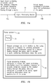
Figure 1 a is a block diagram of a signal processing module according to some embodiments of the present invention. -
Figure 1b is a block diagram of a pump system according to some embodiments of the present invention. -
Figure 2a is a block diagram of a pump system having pump performance monitoring by a slip flow measurement according to some embodiments of the present invention. -
Figure 2b is a diagram showing measured velocity (with slip) and theoretical velocity related to the pump system inFigure 2a . -
Figures 2c(i), 2c(ii) and 2c(iii) are diagrams respectively showing inlet velocity, outlet velocity, and an ideal velocity profile in an impeller for the pump system inFigure 2a . -
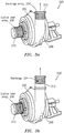
Figure 3a is a block diagram of a pump system having pump performance monitoring using integrated SONAR-based technology according to some embodiments of the present invention. -
Figure 3b is a block diagram of a pump system having pump performance monitoring using external SONAR-based technology according to some embodiments of the present invention. -
Figure 4a is a block diagram of a pump system having pump performance monitoring using pump impeller cavitation monitoring according to some embodiments of the present invention. -
Figure 4b is a graph of frequency versus time showing characteristic frequencies present at a pump startup related to the pump system inFigure 4a . -
Figure 4c is a graph of frequency versus time showing characteristic frequencies present at a pump cavitation related to the pump system inFigure 4a . -
Figure 5 is a graph of a pump signature taken with PVDF-based sensors related to a pump system being monitored through acoustic emissions. -
Figure 6a is a block diagram of a pump system having pump leak detection based on acoustic emissions according to some embodiments of the present invention. -
Figure 6b is a graph of a pump signature of acoustic emissions related to the pump system shown inFigure 6a . -
Figure 7a is a block diagram of a positive displacement pump system being monitored, e.g., by measuring the flow produced by the pump versus the number of pumping strokes, according to some embodiments of the present invention. -
Figure 7b is a diagram of a piston forming part of the positive displacement pump system shown inFigure 7a being stroked inwardly and outwardly. -
Figure 1a shows a processor or signal processing module generally indicated as 10 that features one or more modules configured to receive an input signal alongline 10a containing information about the unsteady pressures and/or acoustic emissions caused by a medium flowing through a pump, and also configured to provide of an output signal alongline 10b containing information about the performance of the pump. - The information about the performance of the pump may include information about (1) pump performance monitoring by a slip flow measurement, (2) monitoring related to predicting impeller wear, (3) pump impeller cavitation monitoring, (4) pump monitoring through acoustic emissions, (5) monitoring related to pump leak detection, (6) pump efficiency monitoring and (7) positive displacement pump monitoring, consistent with that shown and described herein.
- The functionality of the processor or
signal processing module 10 may be implemented using hardware, software, firmware, or a combination thereof. In a typical software implementation, the processor modules would include one or more microprocessor-based architectures having a microprocessor, a random access memory (RAM), a read only memory (ROM), input/output devices and control, data and address buses connecting the same. A person skilled in the art would be able to program such a microprocessor-based implementation to perform the functionality described herein without undue experimentation. The scope of the invention is not intended to be limited to any particular implementation using technology either now known or later developed in the future. - The processor or
signal processing module 10 may be used in relation to one or more pump systems featuring a pump, including centrifugal, bladder, piston or positive displacement pumps, and sensors, including PVDF-based or SONAR-based sensors, for monitoring the performance of the pump, based at least partly on unsteady pressures and/or acoustic emissions sensed on, or in relation to, the pump, consistent with that described below: - Some embodiments of the present invention may take the form of a pump system generally indicated 20 featuring a
pump 22; one ormore sensors 24, including PVDF-based and/or SONAR-based sensors, arranged on, or in relation to, thepump 22, configured to respond to unsteady pressures and/or acoustic emissions caused by a medium flowing through thepump 22, and to provide a signal containing information about the same; and the signal processing module 10 (seeFigure 1a ) configured to receive the signal containing information about the unsteady pressures and/or acoustic emissions caused by the medium flowing through the pump, and also configured to provide of the output signal containing information about the performance of the pump. - The scope of the invention is intended to include pumps like centrifugal, bladder, piston or positive displacement pumps that are known in the art, as well as other types or kinds of pumps either now known or later developed in the future.
- Moreover, the scope of the invention is intended to include sensors like PVDF-based sensors for sensing acoustic emissions or SONAR-based sensors for sensing unsteady pressures that are known in the art, as well as other types or kinds of sensors for sensing the same either now known or later developed in the future. By way of example, the
sensors 24 may take the form in whole or in part of sensors disclosed in United States Patent Nos.7,165,464 ;7,134,320 ;7,363,800 ;7,367,240 ; and7,343,820 . By way of example, the sensors disclosed in the aforementioned patents may be configured to sense the volumetric flow of the medium and provide a signal containing information about the volumetric flow that is not substantially affected by the varying amounts of entrained air in the medium. As a person skilled in the art would appreciate, PVDF-based sensors are made from Polyvinylidene Fluoride, which is a highly non-reactive and pure thermoplastic fluoropolymer. The scope of the invention is also intended to include other types or kinds of SONAR-based VF/GVF meters either now known or later developed in the future that perform the same basic functionality of the SONAR-based VF/GVF meter as such functionality relates to implementing the present invention. -
Figure 2a shows a pump system generally indicated as 100 featuring apump 102 and a SONAR-based array ofsensors 104, as well as the signal processing module, such as module 10 (Figures 1a, 1b ) according to some embodiments of the present invention. - The pump has a casing or liner 102a.
- The SONAR-based
array 104 of sensors is arranged on the casing or liner 102a, and configured to respond to unsteady pressures caused by a medium flowing through thepump 102, including the unsteady pressures caused by an impeller tip velocity and a fluid velocity, and to provide a signal containing information about the same. - The signal processing module, such as module 10 (
Figure 1a ), may be configured to receive the signal containing information about the unsteady pressures caused by the medium flowing through the pump, and may also be configured to provide of an output signal containing information about a slip flow measurement. - According to some embodiments of the present invention, the signal processing module, such as module 10 (
Figures 1a, 1b ), and the SONAR-basedsensor array 104 may be configured to measure slip and ideal velocities. This velocity is the actual impeller tip velocity. The fluid itself will typically have a reduced velocity due to the slip. Thesensor array 104 may be installed on the casing, as shown, in the proper location to measure the unsteady pressures created by both the impeller tip velocity and the fluid velocity in real time. From these pressure measurements, the signal processing module, such as module 10 (Figure 1a ), can be configured to determine the velocities of each knowing the spacing between sensors in thearray 104 and the transition time between sensors. As wear occurs on the impeller, the slip will increase and the difference between the ideal and slip velocity can be monitored and the severity of wear can be determined on a real time basis. - This invention proposes using an array sensors to measure the slip and ideal velocities.
Figures 2b, 2c(ii) and 2c(iii) show the ideal velocity denoted as V2. This velocity is the actual impeller tip velocity. The fluid itself will have a reduced velocity due to the slip. This is denoted as V2' inFigure 2b . - The
pump system 100 or pump 102 may also include one or more elements, devices, apparatus or equipment that are known in the art, do not form part of the underlying invention, and are not disclosed herein or described in detail for that reason. - The scope of the invention re the pump applications is not intended to be limited to the type or kind of medium being processed, or the type of pumping process, either now known or later developed in the future.
-
Figures 3a and 3b show a pump system generally indicated as 200, 200' featuring apump 202 and a SONAR-basedarray Figures 1a, 1b ), according to some embodiments of the present invention. Similar parts inFigures 3a, 3b are identified using similar reference numerals. - The
pump 202 has an impeller (seeFigure 4a ), acasing 208, asuction inlet 210 or adischarge 212. - The SONAR-based array(s) 204, 206 of sensors is arranged on the
casing 208,suction inlet 210 ordischarge 212, and may be configured to respond to unsteady pressures caused by a medium flowing through thepump 202, and to provide a signal containing information about the same. The SONAR array(s) 210, 212 can be integrated as shown inFigure 3a or externally fixtured to pump 202 as shown inFigure 3b . - The signal processing module 10 (
Figures 1a, 1b ) may be configured to receive the signal containing information about the unsteady pressures caused by the medium flowing through thepump 202, and also may be configured to provide of an output signal containing information about the wear of parts of thepump 202, including wear in the back shroud or eye of the impeller. - As a person skilled in the art would appreciate, the velocity within the
discharge 212 and suction end 210 of pumps can be a good indicator for determining the performance of a pump and predicting wear. The signal processing module 10 (Figures 1a, 1b ) and SONAR-based meter may be configured to measure the unsteady pressures and determine the convection velocity. Integrating this technology within thepump casing 208,discharge 212 and orinlet 210, the velocity of the flow can be determined from which the performance of the pump can be obtained. For example, as a person skilled in the art would appreciate, when high velocities are present within the impeller accelerated wear will likely occur on the back shroud of the impeller. Alternatively, if low velocities are present excessive wear due to recirculation of the slurry back to the eye of the impeller will likely cause the eye to wear. - The
pump system 200 or pump 202 may also include one or more elements, devices, apparatus or equipment that are known in the art, do not form part of the underlying invention, and are not disclosed herein or described in detail for that reason. -
Figure 4a shows a pump system generally indicated as 400 featuring acentrifugal pump 402 and one or more PVDF-basedsensors 404, along with the signal processing module, such as module 10 (Figures 1a, 1b ), according to some embodiments of the present invention. - The
centrifugal pump 402 has a pump body and animpeller 402b, and may be coupled to inlet and outlet piping (see, e.g., inlet andoutlet piping elements Figure 7a ). - The one or more PVDF-based
sensors 404 may be arranged in relation to thepump body 402a, as well as the inlet and outlet piping, and is configured to respond to acoustic emissions caused by a medium flowing through thepump 402, including the collapsing of small bubbles caused by the cavitation process created within thepump 402, and to provide a signal containing information about the same. - The signal processing module 10 (
Figures 1a, 1b ) may be configured to receive the signal containing information about the acoustic emissions caused by the medium flowing through the pump, and may also be configured to provide of an output signal containing information about pump impeller cavitation monitoring, including wear of the impeller caused by the cavitation process. - According to some embodiments of the present invention, the signal processing module 10 (
Figures 1a, 1b ) may be configured to compare characteristic frequencies of the acoustic emissions of thepump 402 at startup to associated characteristic frequencies of the acoustic emissions of thepump 402 at a later time caused by the cavitation process. - As a person skilled in the art would appreciate, during the cavitation process, the collapsing of the small bubbles that are created can create acoustic emissions within the
pump 402. These acoustic emissions can be detected by the one or more PVDF-basedsensors 404 and used to identify when cavitation is occurring within the pump. Since the inlet and outlet piping to the pump can act as waveguides to the acoustics generated within the pump the one or more PVDF-basedsensors 404 can be located in multiple locations; on the pump body itself 402a or along the piping (not shown) attached to the pump. -
Figures 4b shows the detection of pump cavitation through the use of the PVDF-basedsensors 404 attached to the inlet side of thecentrifugal pump 402. As seen in the chart inFigure 4b , a pump is started and quickly reaches steady state operation. The chart inFigure 4c demonstrates the acoustic emissions caused by cavitation occurring within the pump. Changes were made to the line pressure causing the pump to begin to cavitate, as indicated by the changes about half way through the data in the chart inFigure 4c . A dramatic change in the acoustic emissions are observed across a wide range of acoustic frequencies. - The
pump system 400 or pump 402 may also include one or more elements, devices, apparatus or equipment that are known in the art, do not form part of the underlying invention, and are not disclosed herein or described in detail for that reason. - There are many equipment diagnostic data analysis techniques that can be utilized to monitor and detect when a pump is malfunctioning, according to the present invention described herein. One such method utilizes a pump "signature" which is taken during normal steady-state operation of the pump. From this type of pump signature characteristic, pump frequencies can be measured and tracked over time. Variations in the frequencies present or the amplitudes of the signals can indicate pump wear and potential failure.
Figure 5 shows an example of a pump signature taken with PVDF-based sensors. - According to some embodiments of the present invention, the acoustic emissions may be monitored while they travel in the fluid on either the inlet or outlet of the pump. The PVDF-based sensors may be attached to either the inside or the outside of a pipe can be used to monitor the acoustic emissions from the pump and can be used to detect conditions such as the cavitation, bearing wear, impeller wear and casing liner damage.
- Some embodiments of the present invention using this type of technique may take the form of a pump system featuring a pump having an inlet and outlet; one or more PVDF-based sensors attached to either the inlet, or the outlet or both of the pump, and configured to respond to acoustic emissions caused by a medium flowing through the pump, including the collapsing of small bubbles caused by the cavitation process created within the pump, and to provide a signal containing information about the same; and a signal processing module that may be configured to receive the signal containing information about the acoustic emissions caused by the medium flowing through the pump, and also may be configured to provide of an output signal containing information about pump monitoring through acoustic emissions, including information about the cavitation, bearing wear, impeller wear or casing liner damage.
- According to some embodiments of the present invention, the signal processing module such as 10 (
Figures 1a, 1b ) may be configured to measure and track signature characteristic pump frequencies over time and determine pump wear or potential failure based on variations in frequency or amplitude in the signature characteristic pump frequencies. -
Figures 6a, 6b show a pump system generally indicated as 600 featuring apump 602 and one or more SONAR-based arrays ofsensors 604, along with the signal processing module, such as module 10 (Figures 1a, 1b ), according to some embodiments of the present invention. - According to some embodiment of the present invention, the acoustic measurement abilities of the SONAR-based
array 604 can be used to identify a specific high frequency . In addition, the array processing capabilities of the system, including the processor or signal processing module 10 (Figures 1a, 1b ), can be used to check the coherence of the frequency signal and determine an emission direction. - As a person skilled in the art would appreciate, the many mating surfaces of the various components in pumps often lead to leaks. These leaks can go for extended periods of time before detection and lead to expensive repair and cleanup. Consistent with that described herein, the acoustic emissions of these leaks can be detected and monitored by SONAR-based processing and technology according to the present invention.
- Additionally, by using the SONAR-based processing and technology according to the present invention, leaks can also be detected within the various components of the pump itself. Internal valves such as those used in bladder pumps and piston pumps can greatly reduce a pumps capacity and efficiency if they leak. The acoustic emissions from such a leak could be detected with this system.
- For example, in
Figure 6a the pump may include, e.g., a bladder pump or a piston pump. - In
Figure 6a , the SONAR-basedarray 604 of sensors may be attached to one or more parts or surfaces of thepump 602, including aninlet 606 of thepump 602, and configured to respond to unsteady pressures caused by a medium flowing through the pump, including the leaks in the internal valves and around the bearings and mating surfaces leaks, and may be configured to provide a signal containing information about the same. - The signal processing module 10 (
Figures 1a, 1b ) may be configured to receive the signal containing information about the unsteady pressures caused by the medium flowing through the pump, and may also be configured to provide of an output signal containing information about pump leak detection, including information about the leaks in internal valves and around bearings and mating surfaces. - The
pump system 600 or pump 602 may also include one or more elements, devices, apparatus or equipment that are known in the art, do not form part of the underlying invention, and are not disclosed herein or described in detail for that reason. - According to some embodiment of the present invention, a technique is provided to monitor the performance of a pump using a SONAR-based flow meter to measure the flow rate of the pumped medium.
- A SONAR-based flow meter, such as SONARtrac® VF-100 which is known in the art, can be used to measure the flow rate through the pump. The SONAR-based technique of flow rate measurement is especially beneficial for liquid slurry flows or particle-laden gas flows where, due to the erosive characteristics of the flow, any intrusive method of flow measurement would be subject to excessive wear and premature failure. The present invention of using a SONAR-based flow meter in combination with pressure and electrical power measurements enables pump efficiency to be monitored continuously and in real-time.
- Some embodiments according to the present invention using this technique may take the form of a pump system featuring a pump; a SONAR-based array of sensors attached to one or more parts or surfaces of the pump, including an inlet of the pump, and configured to respond to unsteady pressures caused by a medium flowing through the pump, and to provide a signal containing information about the same; and a signal processing module that may be configured to receive the signal containing information about the unsteady pressures caused by the medium flowing through the pump, and may also be configured to provide of an output signal containing information about pump efficiency monitoring leak detection, based at least partly on the rate of flow of the medium through the pump.
- According to some embodiment of the present invention, the signal processing module may be configured to provide the output signal based at least partly in response to signalling containing information about intake and discharge pressure and electrical power measurements.
-
Figures 7a, 7b show a pump system generally indicated as 700 featuring apositive displacement pump 702 and one or more SONAR-based arrays ofsensors 704, along with the signal processing module, such as module 10 (Figures 1a, 1b ), according to some embodiments of the present invention. - As a person skilled in the art would appreciate, positive displacements pumps operate by forcing fluid from an inlet pressure section of the pump into the discharge section. According to some embodiments of the present invention, the SONAR-based array may provide several mechanisms for monitoring the operation of these types of positive displacements pumps. Consistent with that described herein re centrifugal pumps, the performance of the pump can be monitored by measuring the flow produced by the
pump 702 versus the number of pumping strokes. Both of these parameters can be measured by the SONAR-based flow meter. The meter in its normal mode of operation can give the material flow rate, while an analysis of the acoustic signals received can be used to track the pumping stroke rate. - Additional information on the wear rate of the pump can also be determined through a more detailed analysis of the acoustic emissions from the pump. The condition of a number of pump components, including seals, diaphragms and valves, can be ascertained from the acoustic signatures the components emit during operation. As an example, in a dual-valve piston style pump, each value may close depending on the stage of the pump. As each valve closes it will emit acoustic signals from the closure as well as possibly emit during the piston compression. The acoustic signature of the valve closing can determine if the valve is closing quickly and completely or if it is starting to wear, inducing more leakage and take additional time to close. Also, if the valve is not closing completely during the compression stage of the pump acoustic emissions of a leakage could be detected.
- In addition, in diaphragm based positive displacement pump the critical diaphragm components could be monitored through its acoustic emissions. A hole or rip in the diaphragm could be detected as high frequency acoustics, while a periodic impulse may indicate a tear that is oscillating.
- Some embodiments of the present invention using this technique may take the form of a pump system featuring such a positive displacement pump; a SONAR-based array of sensors attached to one or more parts or surfaces of the pump, and configured to respond to unsteady pressures and acoustic emissions caused by a medium flowing through the pump, and to provide a signal containing information about the same; and a signal processing module that may be configured to receive the signal containing information about the unsteady pressures and acoustic emissions caused by the medium flowing through the pump, and may also be configured to provide of an output signal containing information about positive displacement pump monitoring, based at least partly on the rate of flow of the pump versus the number of pumping strokes.
- According to some embodiments of the present invention, the information about the rate of flow of the pump may be based at least partly on the unsteady pressures and the number of pumping strokes is based at least partly on the acoustic emissions.
- The
pump system 700 or pump 702 may also include one or more elements, devices, apparatus or equipment that are known in the art, do not form part of the underlying invention, and are not disclosed herein or described in detail for that reason. - According to some embodiments of the present invention, the apparatus may also take the form of a computer-readable storage medium having computer-executable components for performing the steps of the aforementioned method.
- By way of example, the present invention is described in relation to, and part of, a pump system for pumping a medium through a pump. However, the scope of the invention is not intended to be limited to any particular type or kind of system or device for processing a flowing medium being monitored. For example, embodiments are envisioned using, and the scope of the invention is intended to include, other types or kinds of systems, or industrial devices or equipment either now known or later developed in the future.
- While the invention has been described with reference to an exemplary embodiment, it will be understood by those skilled in the art that various changes may be made and equivalents may be substituted for elements thereof without departing from the scope of the invention. In addition, may modifications may be made to adapt a particular situation or material to the teachings of the invention without departing from the essential scope thereof. Therefore, it is intended that the invention not be limited to the particular embodiment(s) disclosed herein as the best mode contemplated for carrying out this invention.
Claims (26)
- Apparatus comprising:one or more sensors (24), including Polyvinylidene Fluoride (PVDF) based and/or SONAR-based sensors, arranged on, or integrated into, or externally attached or fixtured to, one or more parts of a pump (22), the one or more SONAR-based sensors (24) configured to sense and respond to unsteady pressures caused by a medium flowing through the pump (22) and to provide SONAR-based sensed signaling containing information about the sensed unsteady pressures, the one or more PVDF based sensors (24) configured to sense and respond to acoustic emissions caused by the medium flowing through the pump (22) and to provide PVDF-based sensed signaling containing information about the sensed acoustic emissions,a signal processor or processing module (10) configured toreceive as an input signal (10a) the SONAR-based sensed signaling and/or PVDF-based sensed signaling, the signal processor or processing module (10) characterized by further being configured toprovide an output signal (10b) containing information about wear of the one or more parts of the pump (22), based on the input signal received.
- Apparatus according to claim 1, wherein the output signal (10b) contains information about a slip flow measurement.
- Apparatus according to claim 1, wherein the input signal (10a) contains information about the unsteady pressures received from a SONAR-based array (104) arranged in relation to a casing (102a) of the pump (22), particularly where the SONAR-based array is arranged in relation to a suction inlet (210), a discharge (212), or both, or particularly where the SONAR-based array is integrated into the casing (102a), or is externally fixtured to the pump (22).
- Apparatus according to claim 1, wherein the unsteady pressures are created by both the velocity of an impeller tip and the velocity of the medium.
- Apparatus according to claim 1, wherein the signal processor or processing module (10) is configured to determine the velocity of an impeller tip and the velocity of the medium in real time based at least partly on pressure measurements that are a function of the spacing between sensors (24) in a SONAR-based array (104) and the transition time between the sensors (24).
- Apparatus according to claim 1, wherein the signal processor or processing module (10) is configured to measure the slip of the pump (22) and ideal velocities in an impeller (402b) of the pump based at least partly on the unsteady pressures, or wherein the signal processor or processing module (10) is configured to determine a convection velocity based at least partly on the unsteady pressures, or wherein the one or more modules is configured to determine the velocity of the medium flowing in a discharge and suction end of the pump (22) based at least partly on the unsteady pressures.
- Apparatus according to claim 1, wherein the output signal (10b) contains information about high velocities present within an impeller of the pump (22) that can cause accelerated wear on a back shroud of the impeller based at least partly on unsteady pressures, or wherein the output signal (10b) contains information about low velocities present within an impeller of the pump that can cause accelerated wear on an eye of the impeller, including excessive wear due to recirculation of slurry back to the eye, based at least partly on unsteady pressures.
- Apparatus according to claim 1, wherein the signal processor or processing module (10) is configured to determine when cavitation occurs in the pump (22) based at least party on the acoustic emissions.
- Apparatus according to claim 1, wherein the input signal (10a) contains information about the acoustic emissions received from one or more PVDF-based sensors (24) arranged in relation to the pump (22), particularly where the PVDF-based sensors are attached to an inlet side of the pump, including a centrifugal pump (402), or particularly where the PVDF-based sensors (24) are located in multiple locations, including on the body of the pump itself, or along piping attached to the pump, or particularly where the one or more PVDF-based sensors (24) are attached to the inside or the outside of piping arranged in relation to the pump.
- Apparatus according to claim 1, wherein the signal processor or processing module (10) is configured to monitor the acoustic emissions traveling in the medium flowing in the pump (22), including in the medium flowing on either an inlet or an outlet of the pump.
- Apparatus according to claim 1, wherein the signal processor or processing module (10) is configured to detect conditions, including cavitation, bearing wear, impeller wear and casing lining damage, based at least partly on the acoustic emissions.
- Apparatus according to claim 1, wherein the signal processor or processing module (10) is configured to determine a pump signature of the acoustic emissions during normal steady-state operation of the pump taken with PVDF-based sensors (24), particularly where the signal processor or processing module (10) is configured to determine variations in frequency or amplitude in relation to the pump signature that can indicate pump wear and potential failure.
- Apparatus according to claim 1, wherein the signal processor or processing module (10) is configured to detect pump leak conditions, including leaks around bearings, mating surfaces, internal valves including those used in a bladder pump or a piston pump, based at least partly on the acoustic emissions.
- Apparatus according to claim 1, wherein the signal processor or processing module is configured to measure and identify one or more specific high frequencies related to pump leak conditions, based at least partly on the acoustic emissions.
- Apparatus according to claim 1, wherein the signal processor or processing module (10) is configured to check the coherence of a frequency signal and determine an emission direction.
- Apparatus according to claim 1, wherein the signal processor or processing module (10) is configured to monitor pump efficiency, based at least partly on measuring a rate of flow of the medium through the pump (22), pressures at an intake and a discharge of the pump, and power provided to an electric motor driving the pump, particularly where the signal processor or processing module (10) is configured to monitor the pump efficiency continuously and in real time.
- Apparatus according to claim 1, wherein the signal processor or processing module (10) is configured to measure a rate of flow of the medium through a positive displacement pump versus the number of pumping strokes of the positive displacement pump, particularly where the measurement of the rate of flow of the medium is based at least partly on the unsteady pressures and the measurement of the number of pumping strokes of the positive displacement pump is based at least partly on the acoustic emissions, or particularly where the signal processor or processing module (10) is configured to monitor the condition of one or more pump components, including seals, diaphragms, valves, based at least partly on the acoustic emissions, or particularly where the signal processor or processing module (10) is configured to monitor the condition of a dual valve piston style pump, including closing of valves and piston compression, based at least partly on the acoustic emissions.
- Apparatus according to claim 1, wherein the signal processor or processing module (10) is configured to measure a rate of flow of the medium through a positive displacement pump versus the number of pumping strokes of the positive displacement pump, particularly where the one or more modules is configured to monitor the condition of the closing of valves to detect if a valve is closing to quickly and completely, or if the valve is starting to wear, including providing more leakage or taking additional time to close, or if the valve is not closing completely during the compression stage where pump acoustic emissions of a leakage can be detected, or particularly where the signal processor or processing module is configured to monitor the condition of a diaphragm-based positive displacement pump, based at least partly on the acoustic emissions, including monitoring for a hole or a rip in a diaphragm that could be detected as high frequency acoustics, or monitoring for a tear that is oscillating in the diaphragm that could be detected as a periodic pulse.
- A pump system (20) comprising:a pump (22);andan apparatus of one of claims 1-18, the signal processor or processing module (10) configured to receive the input signal (10a) containing information about the unsteady pressures and/or acoustic emissions caused by the medium flowing through the pump (22), and also configured to provide the output signal (10b) containing information about wear of the one or more parts of the pump.
- A pump system (20) comprising:a pump (102) having a casing (102a) or a liner;a SONAR-based array of sensors (104) arranged on the casing (102a) or liner, and configured to respond to unsteady pressures caused by a medium flowing through the pump (102), including the unsteady pressures caused by an impeller tip velocity and a fluid velocity, and to provide a signal containing information about the same; andan apparatus of one of claims 1-18, the signal processor or processing module (10) configured to receive the signal as the input signal (10a) containing information about the unsteady pressures caused by the medium flowing through the pump, and also configured to provide the output signal (10b) containing information about a slip flow measurement related to the performance of the pump.
- A pump system (20) comprising:a pump (202) having an impeller, a casing, a suction inlet or a discharge;a SONAR-based array of sensors (204, 206) arranged on the casing (208), suction inlet (210) or discharge (212), and configured to respond to unsteady pressures caused by a medium flowing through the pump, and to provide a signal containing information about the same; andan apparatus of one of claims 1-18, the signal processor or processing module (10) configured to receive the signal as the input signal (10a) containing information about the unsteady pressures caused by the medium flowing through the pump, and also configured to provide the output signal (10b) containing information about wear of parts of the pump, including wear in the back shroud or eye of the impeller.
- A pump system (20) comprising:a centrifugal pump (402) having a pump body and an impeller (402b), and being coupled to inlet and outlet piping;one or more Polyvinylidene Fluoride, PVDF, based sensors (404) arranged in relation to the pump body or inlet and outlet piping, and configured to respond to acoustic emissions caused by a medium flowing through the pump, including the collapsing of small bubbles caused by the cavitation process created within the pump, and to provide a signal containing information about the same; andan apparatus of one of claims 1-18, the signal processor or processing module (10) configured to receive the signal as the input signal (10a) containing information about the acoustic emissions caused by the medium flowing through the pump, and also configured to provide the output signal (10b) containing information about pump impeller cavitation monitoring, including wear of the impeller caused by the cavitation process, particularly wherein the signal processor or processing module (10) is configured to compare characteristic frequencies of the acoustic emissions of the pump at startup to associated characteristic frequencies of the acoustic emissions of the pump at a later time caused by the cavitation process.
- A pump system (20) comprising:a pump (22) having an inlet and outlet;one or more PVDF-based sensor (24) attached to either the inlet, or the outlet or both of the pump, and configured to respond to acoustic emissions caused by a medium flowing through the pump, including the collapsing of small bubbles caused by the cavitation process created within the pump, and to provide a signal containing information about the same; andan apparatus of one of claims 1-18, the signal processor or processing module (10) configured to receive the signal as the input signal (10a) containing information about the acoustic emissions caused by the medium flowing through the pump, and also configured to provide the output signal (10b) containing information about pump monitoring through acoustic emissions, including information about cavitation, bearing wear, impeller wear or casing liner damage, particularly wherein the signal processor or processing module (10) is configured to measure and track signature characteristic pump frequencies over time and determine pump wear or potential failure based at least partly on variations in frequency or amplitude in the signature characteristic pump frequencies.
- A pump system (20) comprising:a pump (602), including a bladder pump or a piston pump;a SONAR-based array of sensors (604) attached to one or more parts or surfaces of the pump, including an inlet of the pump, and configured to respond to unsteady pressures caused by a medium flowing through the pump, including leaks in internal valves and around bearings and mating surfaces leaks, and to provide a signal containing information about the same; andan apparatus of one of claims 1-18, the signal processor or processing module (10) configured to receive the signal as the input signal (10a) containing information about the unsteady pressures caused by the medium flowing through the pump, and also configured to provide the output signal (10b) containing information about pump leak detection, including information about the leaks in internal valves and around bearings and mating surfaces.
- A pump system (20) comprising:a pump (22);a SONAR-based array of sensors (24) attached to one or more parts or surfaces of the pump, including an inlet of the pump, and configured to respond to unsteady pressures caused by a medium flowing through the pump, and to provide a signal containing information about the same; andan apparatus of one of claims 1-18, the signal processor or processing module (10) configured to receive the signal as the input signal (10a) containing information about the unsteady pressures caused by the medium flowing through the pump, and also configured to provide the output signal (10b) containing information about pump efficiency monitoring leak detection, based at least partly on the rate of flow of the medium through the pump.
- A pump system (20) comprising:a positive displacement pump (702);a SONAR-based array of sensors (24) attached to one or more parts or surfaces of the pump, and configured to respond to unsteady pressures and acoustic emissions caused by a medium flowing through the pump, and to provide a signal containing information about the same; andan apparatus of one of claims 1-18, the signal processor or processing module (10) configured to receive the signal as the input signal (10a) containing information about the unsteady pressures and acoustic emissions caused by the medium flowing through the pump, and also configured to provide the output signal (10b) containing information about positive displacement pump monitoring, based at least partly on the rate of flow of the pump versus the number of pumping strokes, particularly wherein the information about the rate of flow of the pump is based at least partly on the unsteady pressures and the number of pumping strokes is based at least partly on the acoustic emissions.
Applications Claiming Priority (8)
| Application Number | Priority Date | Filing Date | Title |
|---|---|---|---|
| US5460008P | 2008-05-20 | 2008-05-20 | |
| US5456608P | 2008-05-20 | 2008-05-20 | |
| US5459208P | 2008-05-20 | 2008-05-20 | |
| US5473208P | 2008-05-20 | 2008-05-20 | |
| US5457508P | 2008-05-20 | 2008-05-20 | |
| US5460808P | 2008-05-20 | 2008-05-20 | |
| US5490108P | 2008-05-21 | 2008-05-21 | |
| PCT/US2009/044658 WO2009143232A1 (en) | 2008-05-20 | 2009-05-20 | Applications of pump performance monitoring |
Publications (3)
| Publication Number | Publication Date |
|---|---|
| EP2296724A1 EP2296724A1 (en) | 2011-03-23 |
| EP2296724A4 EP2296724A4 (en) | 2014-11-05 |
| EP2296724B1 true EP2296724B1 (en) | 2019-12-25 |
Family
ID=41340521
Family Applications (1)
| Application Number | Title | Priority Date | Filing Date |
|---|---|---|---|
| EP09751460.8A Active EP2296724B1 (en) | 2008-05-20 | 2009-05-20 | Applications of pump performance monitoring |
Country Status (7)
| Country | Link |
|---|---|
| US (1) | US9062682B2 (en) |
| EP (1) | EP2296724B1 (en) |
| CN (1) | CN102076367B (en) |
| AU (1) | AU2009249092B2 (en) |
| CA (1) | CA2724786C (en) |
| MX (1) | MX340167B (en) |
| WO (1) | WO2009143232A1 (en) |
Families Citing this family (35)
| Publication number | Priority date | Publication date | Assignee | Title |
|---|---|---|---|---|
| US20120141301A1 (en) * | 2009-06-12 | 2012-06-07 | Cidra Corporate Services Inc. | Method and apparatus for predicting maintenance needs of a pump based at least partly on pump performance analysis |
| US8043054B2 (en) * | 2010-08-25 | 2011-10-25 | General Electric Company | Method and system for monitoring wind turbine |
| US9243631B2 (en) | 2011-04-07 | 2016-01-26 | Imo Industries, Inc. | System and method for monitoring pump lining wear |
| CN103527497A (en) * | 2012-07-04 | 2014-01-22 | 北京精密机电控制设备研究所 | Device for testing flow field and cavitation of impeller pump |
| US10274364B2 (en) * | 2013-01-14 | 2019-04-30 | Virginia Tech Intellectual Properties, Inc. | Analysis of component having engineered internal space for fluid flow |
| DE102013017828B4 (en) * | 2013-10-24 | 2015-05-13 | Fresenius Medical Care Deutschland Gmbh | Method and device for monitoring an in an extracorporeal blood circulation or arranged in a Dialysatkreislauf impeller pump and blood treatment device |
| GB2523116B (en) * | 2014-02-12 | 2020-04-08 | Salunda Ltd | Sensor system for a pump impeller assembly |
| DE102015201203B4 (en) * | 2015-01-26 | 2016-12-15 | Voith Patent Gmbh | Method for detecting cavitation |
| DE102015004968A1 (en) * | 2015-04-20 | 2016-10-20 | Xenios Ag | Method for conveying a medium with a pump and pump with a rotor, a housing and a drive |
| US10724999B2 (en) | 2015-06-04 | 2020-07-28 | Rolls-Royce Corporation | Thermal spray diagnostics |
| US10241091B2 (en) | 2015-06-04 | 2019-03-26 | Rolls-Royce Corporation | Diagnosis of thermal spray gun ignition |
| DE102016201901A1 (en) | 2016-02-09 | 2017-06-14 | Voith Patent Gmbh | Sensor arrangement and method for locating cavitation |
| US10711802B2 (en) * | 2016-05-16 | 2020-07-14 | Weir Minerals Australia Ltd. | Pump monitoring |
| WO2018017716A1 (en) | 2016-07-21 | 2018-01-25 | Tc1 Llc | Rotary seal for cantilevered rotor pump and methods for axial flow blood pumping |
| US10660998B2 (en) | 2016-08-12 | 2020-05-26 | Tci Llc | Devices and methods for monitoring bearing and seal performance |
| EP3315783B1 (en) | 2016-10-27 | 2021-09-29 | Sulzer Management AG | A method of and an arrangement for monitoring the condition of a volute casing of a centrifugal pump |
| EP3336536B1 (en) | 2016-12-06 | 2019-10-23 | Rolls-Royce Corporation | System control based on acoustic signals |
| US11143758B2 (en) * | 2017-10-13 | 2021-10-12 | Navico Holding As | Sonar transducer performance optimization |
| US11181111B2 (en) * | 2018-02-27 | 2021-11-23 | Oshkosh Corporation | Fluid delivery system health monitoring systems and methods |
| US20190292734A1 (en) * | 2018-03-26 | 2019-09-26 | Roadtec, Inc. | Method and apparatus for avoiding or ameliorating cavitation in an asphalt cement fluid circuit |
| CN109058089A (en) * | 2018-06-13 | 2018-12-21 | 天津大学 | A method of the vacuum pump overload fault detection based on acoustic emission signal |
| EP3586973B1 (en) | 2018-06-18 | 2024-02-14 | Rolls-Royce Corporation | System control based on acoustic and image signals |
| CN109162910B (en) * | 2018-06-29 | 2020-03-17 | 武汉船用机械有限责任公司 | Cargo oil pump performance testing device and testing method |
| CN109268201A (en) * | 2018-09-06 | 2019-01-25 | 湖南江河机电自动化设备股份有限公司 | A kind of rotary wheel of water turbine abrasion big data analysis system |
| CN114585816B (en) * | 2019-09-18 | 2025-01-07 | 伟尔矿物澳大利亚私人有限公司 | Sensing device, system and method for pump |
| US11273246B2 (en) * | 2019-11-12 | 2022-03-15 | Fresenius Mesical Care Holdings, Inc. | Piston assembly including leak detection in a dialysis machine |
| PE20230009A1 (en) | 2020-04-09 | 2023-01-09 | Spm Instr Ab | SYSTEM TO CONTROL THE INTERNAL STATE OF A DRUM MILL |
| US12071208B2 (en) | 2020-06-01 | 2024-08-27 | Brunswick Corporation | System and peripheral devices for a marine vessel |
| US20220154720A1 (en) * | 2020-11-19 | 2022-05-19 | Brunswick Corporation | Bilge pump systems |
| US11796993B2 (en) | 2021-05-12 | 2023-10-24 | Yokogawa Electric Corporation | Systems, methods, and devices for equipment monitoring and fault prediction |
| US12535086B2 (en) | 2021-10-09 | 2026-01-27 | S.P.M. Instrument Ab | System and method for pump control based on pump vibrations |
| CN113847231A (en) * | 2021-10-22 | 2021-12-28 | 珠海格力电器股份有限公司 | A compressor with self-diagnosis to prevent failure |
| CN115217461B (en) * | 2022-07-19 | 2025-03-18 | 上海中联重科桩工机械有限公司 | Performance detection method, device and computer storage medium for main pump of rotary drilling rig |
| CN115524107B (en) * | 2022-09-30 | 2026-04-14 | 中铁工程服务有限公司 | Shield tunneling machine foam screw pump performance detection system and detection method thereof |
| SE2550826A1 (en) * | 2022-10-10 | 2025-09-09 | Spm Instr Ab | A Process Optimization System |
Citations (2)
| Publication number | Priority date | Publication date | Assignee | Title |
|---|---|---|---|---|
| WO2003062759A1 (en) * | 2002-01-23 | 2003-07-31 | Cidra Corporation | Apparatus and method for measuring parameters of a mixture having solid particles suspended in a fluid flowing in a pipe |
| WO2005012843A2 (en) * | 2003-08-01 | 2005-02-10 | Cidra Corporation | Method and apparatus for measuring parameters of a fluid flowing within a pipe using a configurable array of sensors |
Family Cites Families (16)
| Publication number | Priority date | Publication date | Assignee | Title |
|---|---|---|---|---|
| US5575310A (en) * | 1986-03-04 | 1996-11-19 | Deka Products Limited Partnership | Flow control system with volume-measuring system using a resonatable mass |
| ATE162621T1 (en) * | 1990-11-19 | 1998-02-15 | Deka Products Lp | PUMP CONTROL DEVICE WITH ACOUSTIC SPECTRAL ANALYSIS |
| US5249932A (en) * | 1991-10-07 | 1993-10-05 | Erik Van Bork | Apparatus for controlling diaphragm extension in a diaphragm metering pump |
| US6757665B1 (en) * | 1999-09-28 | 2004-06-29 | Rockwell Automation Technologies, Inc. | Detection of pump cavitation/blockage and seal failure via current signature analysis |
| US6422093B2 (en) * | 1999-12-10 | 2002-07-23 | Murray Feller | Burst mode ultrasonic flow sensor |
| CN1266179A (en) * | 2000-04-12 | 2000-09-13 | 姜家玉 | Method and equipment for measuring and adjusting the speed of liquid flowing in and out sealed container |
| US6853951B2 (en) * | 2001-12-07 | 2005-02-08 | Battelle Memorial Institute | Methods and systems for analyzing the degradation and failure of mechanical systems |
| US7165464B2 (en) * | 2002-11-15 | 2007-01-23 | Cidra Corporation | Apparatus and method for providing a flow measurement compensated for entrained gas |
| US7028543B2 (en) * | 2003-01-21 | 2006-04-18 | Weatherford/Lamb, Inc. | System and method for monitoring performance of downhole equipment using fiber optic based sensors |
| US7134320B2 (en) * | 2003-07-15 | 2006-11-14 | Cidra Corporation | Apparatus and method for providing a density measurement augmented for entrained gas |
| RU2324171C2 (en) * | 2003-07-18 | 2008-05-10 | Роузмаунт Инк. | Process diagnostic |
| ATE528623T1 (en) * | 2004-05-17 | 2011-10-15 | Expro Meters Inc | DEVICE AND METHOD FOR MEASURING THE COMPOSITION OF A MIXTURE FLOWING IN A TUBE |
| MX2007014705A (en) * | 2005-05-27 | 2008-02-15 | Cidra Corp | An apparatus and method for measuring a parameter of a multiphase flow. |
| US8641813B2 (en) * | 2005-07-07 | 2014-02-04 | Expro Meters, Inc. | System and method for optimizing a gas/liquid separation process |
| WO2007009097A1 (en) * | 2005-07-13 | 2007-01-18 | Cidra Corporation | Method and apparatus for measuring parameters of a fluid flow using an array of sensors |
| FR2974633B1 (en) * | 2011-04-28 | 2013-10-18 | Snecma | METHOD FOR DETERMINING FLUID FLOW SPEED AND DEVICE FOR IMPLEMENTING THE SAME |
-
2009
- 2009-05-20 US US12/992,927 patent/US9062682B2/en active Active
- 2009-05-20 CA CA2724786A patent/CA2724786C/en active Active
- 2009-05-20 CN CN200980124719.3A patent/CN102076367B/en active Active
- 2009-05-20 WO PCT/US2009/044658 patent/WO2009143232A1/en not_active Ceased
- 2009-05-20 AU AU2009249092A patent/AU2009249092B2/en active Active
- 2009-05-20 EP EP09751460.8A patent/EP2296724B1/en active Active
- 2009-05-20 MX MX2010012659A patent/MX340167B/en active IP Right Grant
Patent Citations (2)
| Publication number | Priority date | Publication date | Assignee | Title |
|---|---|---|---|---|
| WO2003062759A1 (en) * | 2002-01-23 | 2003-07-31 | Cidra Corporation | Apparatus and method for measuring parameters of a mixture having solid particles suspended in a fluid flowing in a pipe |
| WO2005012843A2 (en) * | 2003-08-01 | 2005-02-10 | Cidra Corporation | Method and apparatus for measuring parameters of a fluid flowing within a pipe using a configurable array of sensors |
Also Published As
| Publication number | Publication date |
|---|---|
| CN102076367A (en) | 2011-05-25 |
| AU2009249092B2 (en) | 2015-05-07 |
| US9062682B2 (en) | 2015-06-23 |
| US20110118998A1 (en) | 2011-05-19 |
| MX340167B (en) | 2016-06-29 |
| CA2724786C (en) | 2017-08-22 |
| WO2009143232A1 (en) | 2009-11-26 |
| CN102076367B (en) | 2015-08-12 |
| AU2009249092A1 (en) | 2009-11-26 |
| CA2724786A1 (en) | 2009-11-26 |
| EP2296724A1 (en) | 2011-03-23 |
| MX2010012659A (en) | 2011-02-23 |
| EP2296724A4 (en) | 2014-11-05 |
Similar Documents
| Publication | Publication Date | Title |
|---|---|---|
| US9062682B2 (en) | Applications of pump performance monitoring | |
| JP6422707B2 (en) | Fault diagnosis device for hydraulic pump | |
| US7623986B2 (en) | System and method for power pump performance monitoring and analysis | |
| US20100300683A1 (en) | Real Time Pump Monitoring | |
| EP2796719B1 (en) | Gas compressor and abrasion state determining method | |
| US20080240932A1 (en) | Pump, real-time, general and incremental condition diagnosis | |
| CN1853098A (en) | Process diagnostics | |
| US10907631B2 (en) | Pump ripple pressure monitoring for incompressible fluid systems | |
| TWI782753B (en) | A method for detecting leakage in a positive displacement pump | |
| AU2011328429B2 (en) | Method and system for identifying damage to piston membrane pumps containing working fluids | |
| US7693684B2 (en) | Process, sensor and diagnosis device for pump diagnosis | |
| CN107917069A (en) | Reciprocating compressor sensing flux | |
| US20190154031A1 (en) | Pump Monitoring Using Acoustical Characterizations | |
| Ganeriwala et al. | Using vibration signatures analysis to detect cavitation in centrifugal pumps | |
| JP4822745B2 (en) | Pressure pulsation analyzer | |
| Bury et al. | Leakage location in high pressure external gear pump | |
| Isermann | Fault diagnosis of pumps | |
| Marscher et al. | Pump Cavitation Severity Evaluation Using Accelerometers and Dynamic Pressure Transducers after Installation | |
| Gamarra et al. | Pump Cavitation Severity Evaluation Using Accelerometers and Dynamic Pressure Transducers after Installation | |
| GB2430496A (en) | Measuring input power and flow rate in a pipline for determining a leakage or blockage condition | |
| JP2003139068A (en) | Pump vibration prediction / prevention method and apparatus, and pump | |
| Onari et al. | 46TH TURBOMACHINERY & 33RD PUMP SYMPOSIA HOUSTON, TEXAS I DECEMBER 11-14, 2017 GEORGE R. BROWN CONVENTION CENTER Pump Cavitation Severity Evaluation Using Accelerometers and Dynamic Pressure Transducers after Installation | |
| Udayakumar et al. | In Situ Performance Evaluation of Industrial Reciprocating Air Compressors |
Legal Events
| Date | Code | Title | Description |
|---|---|---|---|
| PUAI | Public reference made under article 153(3) epc to a published international application that has entered the european phase |
Free format text: ORIGINAL CODE: 0009012 |
|
| 17P | Request for examination filed |
Effective date: 20101215 |
|
| AK | Designated contracting states |
Kind code of ref document: A1 Designated state(s): AT BE BG CH CY CZ DE DK EE ES FI FR GB GR HR HU IE IS IT LI LT LU LV MC MK MT NL NO PL PT RO SE SI SK TR |
|
| AX | Request for extension of the european patent |
Extension state: AL BA RS |
|
| DAX | Request for extension of the european patent (deleted) | ||
| A4 | Supplementary search report drawn up and despatched |
Effective date: 20141009 |
|
| RIC1 | Information provided on ipc code assigned before grant |
Ipc: A61M 1/00 20060101AFI20141002BHEP |
|
| STAA | Information on the status of an ep patent application or granted ep patent |
Free format text: STATUS: EXAMINATION IS IN PROGRESS |
|
| 17Q | First examination report despatched |
Effective date: 20180430 |
|
| GRAP | Despatch of communication of intention to grant a patent |
Free format text: ORIGINAL CODE: EPIDOSNIGR1 |
|
| STAA | Information on the status of an ep patent application or granted ep patent |
Free format text: STATUS: GRANT OF PATENT IS INTENDED |
|
| INTG | Intention to grant announced |
Effective date: 20190812 |
|
| GRAS | Grant fee paid |
Free format text: ORIGINAL CODE: EPIDOSNIGR3 |
|
| GRAA | (expected) grant |
Free format text: ORIGINAL CODE: 0009210 |
|
| STAA | Information on the status of an ep patent application or granted ep patent |
Free format text: STATUS: THE PATENT HAS BEEN GRANTED |
|
| AK | Designated contracting states |
Kind code of ref document: B1 Designated state(s): AT BE BG CH CY CZ DE DK EE ES FI FR GB GR HR HU IE IS IT LI LT LU LV MC MK MT NL NO PL PT RO SE SI SK TR |
|
| REG | Reference to a national code |
Ref country code: GB Ref legal event code: FG4D |
|
| REG | Reference to a national code |
Ref country code: CH Ref legal event code: EP |
|
| REG | Reference to a national code |
Ref country code: DE Ref legal event code: R096 Ref document number: 602009060815 Country of ref document: DE |
|
| REG | Reference to a national code |
Ref country code: AT Ref legal event code: REF Ref document number: 1216446 Country of ref document: AT Kind code of ref document: T Effective date: 20200115 |
|
| REG | Reference to a national code |
Ref country code: IE Ref legal event code: FG4D |
|
| REG | Reference to a national code |
Ref country code: NL Ref legal event code: FP |
|
| PG25 | Lapsed in a contracting state [announced via postgrant information from national office to epo] |
Ref country code: SE Free format text: LAPSE BECAUSE OF FAILURE TO SUBMIT A TRANSLATION OF THE DESCRIPTION OR TO PAY THE FEE WITHIN THE PRESCRIBED TIME-LIMIT Effective date: 20191225 Ref country code: LV Free format text: LAPSE BECAUSE OF FAILURE TO SUBMIT A TRANSLATION OF THE DESCRIPTION OR TO PAY THE FEE WITHIN THE PRESCRIBED TIME-LIMIT Effective date: 20191225 Ref country code: GR Free format text: LAPSE BECAUSE OF FAILURE TO SUBMIT A TRANSLATION OF THE DESCRIPTION OR TO PAY THE FEE WITHIN THE PRESCRIBED TIME-LIMIT Effective date: 20200326 Ref country code: LT Free format text: LAPSE BECAUSE OF FAILURE TO SUBMIT A TRANSLATION OF THE DESCRIPTION OR TO PAY THE FEE WITHIN THE PRESCRIBED TIME-LIMIT Effective date: 20191225 Ref country code: FI Free format text: LAPSE BECAUSE OF FAILURE TO SUBMIT A TRANSLATION OF THE DESCRIPTION OR TO PAY THE FEE WITHIN THE PRESCRIBED TIME-LIMIT Effective date: 20191225 Ref country code: BG Free format text: LAPSE BECAUSE OF FAILURE TO SUBMIT A TRANSLATION OF THE DESCRIPTION OR TO PAY THE FEE WITHIN THE PRESCRIBED TIME-LIMIT Effective date: 20200325 Ref country code: NO Free format text: LAPSE BECAUSE OF FAILURE TO SUBMIT A TRANSLATION OF THE DESCRIPTION OR TO PAY THE FEE WITHIN THE PRESCRIBED TIME-LIMIT Effective date: 20200325 |
|
| REG | Reference to a national code |
Ref country code: LT Ref legal event code: MG4D |
|
| PG25 | Lapsed in a contracting state [announced via postgrant information from national office to epo] |
Ref country code: HR Free format text: LAPSE BECAUSE OF FAILURE TO SUBMIT A TRANSLATION OF THE DESCRIPTION OR TO PAY THE FEE WITHIN THE PRESCRIBED TIME-LIMIT Effective date: 20191225 |
|
| PG25 | Lapsed in a contracting state [announced via postgrant information from national office to epo] |
Ref country code: EE Free format text: LAPSE BECAUSE OF FAILURE TO SUBMIT A TRANSLATION OF THE DESCRIPTION OR TO PAY THE FEE WITHIN THE PRESCRIBED TIME-LIMIT Effective date: 20191225 Ref country code: CZ Free format text: LAPSE BECAUSE OF FAILURE TO SUBMIT A TRANSLATION OF THE DESCRIPTION OR TO PAY THE FEE WITHIN THE PRESCRIBED TIME-LIMIT Effective date: 20191225 Ref country code: RO Free format text: LAPSE BECAUSE OF FAILURE TO SUBMIT A TRANSLATION OF THE DESCRIPTION OR TO PAY THE FEE WITHIN THE PRESCRIBED TIME-LIMIT Effective date: 20191225 Ref country code: PT Free format text: LAPSE BECAUSE OF FAILURE TO SUBMIT A TRANSLATION OF THE DESCRIPTION OR TO PAY THE FEE WITHIN THE PRESCRIBED TIME-LIMIT Effective date: 20200520 |
|
| PG25 | Lapsed in a contracting state [announced via postgrant information from national office to epo] |
Ref country code: SK Free format text: LAPSE BECAUSE OF FAILURE TO SUBMIT A TRANSLATION OF THE DESCRIPTION OR TO PAY THE FEE WITHIN THE PRESCRIBED TIME-LIMIT Effective date: 20191225 Ref country code: IS Free format text: LAPSE BECAUSE OF FAILURE TO SUBMIT A TRANSLATION OF THE DESCRIPTION OR TO PAY THE FEE WITHIN THE PRESCRIBED TIME-LIMIT Effective date: 20200425 |
|
| REG | Reference to a national code |
Ref country code: DE Ref legal event code: R097 Ref document number: 602009060815 Country of ref document: DE |
|
| PG25 | Lapsed in a contracting state [announced via postgrant information from national office to epo] |
Ref country code: ES Free format text: LAPSE BECAUSE OF FAILURE TO SUBMIT A TRANSLATION OF THE DESCRIPTION OR TO PAY THE FEE WITHIN THE PRESCRIBED TIME-LIMIT Effective date: 20191225 Ref country code: DK Free format text: LAPSE BECAUSE OF FAILURE TO SUBMIT A TRANSLATION OF THE DESCRIPTION OR TO PAY THE FEE WITHIN THE PRESCRIBED TIME-LIMIT Effective date: 20191225 |
|
| PLBE | No opposition filed within time limit |
Free format text: ORIGINAL CODE: 0009261 |
|
| STAA | Information on the status of an ep patent application or granted ep patent |
Free format text: STATUS: NO OPPOSITION FILED WITHIN TIME LIMIT |
|
| REG | Reference to a national code |
Ref country code: AT Ref legal event code: MK05 Ref document number: 1216446 Country of ref document: AT Kind code of ref document: T Effective date: 20191225 |
|
| PG25 | Lapsed in a contracting state [announced via postgrant information from national office to epo] |
Ref country code: SI Free format text: LAPSE BECAUSE OF FAILURE TO SUBMIT A TRANSLATION OF THE DESCRIPTION OR TO PAY THE FEE WITHIN THE PRESCRIBED TIME-LIMIT Effective date: 20191225 |
|
| 26N | No opposition filed |
Effective date: 20200928 |
|
| PG25 | Lapsed in a contracting state [announced via postgrant information from national office to epo] |
Ref country code: MC Free format text: LAPSE BECAUSE OF FAILURE TO SUBMIT A TRANSLATION OF THE DESCRIPTION OR TO PAY THE FEE WITHIN THE PRESCRIBED TIME-LIMIT Effective date: 20191225 Ref country code: AT Free format text: LAPSE BECAUSE OF FAILURE TO SUBMIT A TRANSLATION OF THE DESCRIPTION OR TO PAY THE FEE WITHIN THE PRESCRIBED TIME-LIMIT Effective date: 20191225 Ref country code: IT Free format text: LAPSE BECAUSE OF FAILURE TO SUBMIT A TRANSLATION OF THE DESCRIPTION OR TO PAY THE FEE WITHIN THE PRESCRIBED TIME-LIMIT Effective date: 20191225 |
|
| PG25 | Lapsed in a contracting state [announced via postgrant information from national office to epo] |
Ref country code: PL Free format text: LAPSE BECAUSE OF FAILURE TO SUBMIT A TRANSLATION OF THE DESCRIPTION OR TO PAY THE FEE WITHIN THE PRESCRIBED TIME-LIMIT Effective date: 20191225 |
|
| REG | Reference to a national code |
Ref country code: BE Ref legal event code: MM Effective date: 20200531 |
|
| PG25 | Lapsed in a contracting state [announced via postgrant information from national office to epo] |
Ref country code: LU Free format text: LAPSE BECAUSE OF NON-PAYMENT OF DUE FEES Effective date: 20200520 |
|
| PG25 | Lapsed in a contracting state [announced via postgrant information from national office to epo] |
Ref country code: IE Free format text: LAPSE BECAUSE OF NON-PAYMENT OF DUE FEES Effective date: 20200520 |
|
| PG25 | Lapsed in a contracting state [announced via postgrant information from national office to epo] |
Ref country code: BE Free format text: LAPSE BECAUSE OF NON-PAYMENT OF DUE FEES Effective date: 20200531 |
|
| PG25 | Lapsed in a contracting state [announced via postgrant information from national office to epo] |
Ref country code: TR Free format text: LAPSE BECAUSE OF FAILURE TO SUBMIT A TRANSLATION OF THE DESCRIPTION OR TO PAY THE FEE WITHIN THE PRESCRIBED TIME-LIMIT Effective date: 20191225 Ref country code: MT Free format text: LAPSE BECAUSE OF FAILURE TO SUBMIT A TRANSLATION OF THE DESCRIPTION OR TO PAY THE FEE WITHIN THE PRESCRIBED TIME-LIMIT Effective date: 20191225 Ref country code: CY Free format text: LAPSE BECAUSE OF FAILURE TO SUBMIT A TRANSLATION OF THE DESCRIPTION OR TO PAY THE FEE WITHIN THE PRESCRIBED TIME-LIMIT Effective date: 20191225 |
|
| PG25 | Lapsed in a contracting state [announced via postgrant information from national office to epo] |
Ref country code: MK Free format text: LAPSE BECAUSE OF FAILURE TO SUBMIT A TRANSLATION OF THE DESCRIPTION OR TO PAY THE FEE WITHIN THE PRESCRIBED TIME-LIMIT Effective date: 20191225 |
|
| PGFP | Annual fee paid to national office [announced via postgrant information from national office to epo] |
Ref country code: NL Payment date: 20220518 Year of fee payment: 14 |
|
| PGFP | Annual fee paid to national office [announced via postgrant information from national office to epo] |
Ref country code: GB Payment date: 20220523 Year of fee payment: 14 Ref country code: FR Payment date: 20220523 Year of fee payment: 14 |
|
| PGFP | Annual fee paid to national office [announced via postgrant information from national office to epo] |
Ref country code: CH Payment date: 20220523 Year of fee payment: 14 |
|
| PGFP | Annual fee paid to national office [announced via postgrant information from national office to epo] |
Ref country code: DE Payment date: 20220627 Year of fee payment: 14 |
|
| REG | Reference to a national code |
Ref country code: DE Ref legal event code: R119 Ref document number: 602009060815 Country of ref document: DE |
|
| REG | Reference to a national code |
Ref country code: CH Ref legal event code: PL |
|
| REG | Reference to a national code |
Ref country code: NL Ref legal event code: MM Effective date: 20230601 |
|
| GBPC | Gb: european patent ceased through non-payment of renewal fee |
Effective date: 20230520 |
|
| PG25 | Lapsed in a contracting state [announced via postgrant information from national office to epo] |
Ref country code: LI Free format text: LAPSE BECAUSE OF NON-PAYMENT OF DUE FEES Effective date: 20230531 Ref country code: CH Free format text: LAPSE BECAUSE OF NON-PAYMENT OF DUE FEES Effective date: 20230531 |
|
| PG25 | Lapsed in a contracting state [announced via postgrant information from national office to epo] |
Ref country code: NL Free format text: LAPSE BECAUSE OF NON-PAYMENT OF DUE FEES Effective date: 20230601 |
|
| PG25 | Lapsed in a contracting state [announced via postgrant information from national office to epo] |
Ref country code: DE Free format text: LAPSE BECAUSE OF NON-PAYMENT OF DUE FEES Effective date: 20231201 Ref country code: GB Free format text: LAPSE BECAUSE OF NON-PAYMENT OF DUE FEES Effective date: 20230520 |
|
| PG25 | Lapsed in a contracting state [announced via postgrant information from national office to epo] |
Ref country code: FR Free format text: LAPSE BECAUSE OF NON-PAYMENT OF DUE FEES Effective date: 20230531 |