EP2296601B1 - Patient lift with hanger bar attachment - Google Patents
Patient lift with hanger bar attachment Download PDFInfo
- Publication number
- EP2296601B1 EP2296601B1 EP09790267A EP09790267A EP2296601B1 EP 2296601 B1 EP2296601 B1 EP 2296601B1 EP 09790267 A EP09790267 A EP 09790267A EP 09790267 A EP09790267 A EP 09790267A EP 2296601 B1 EP2296601 B1 EP 2296601B1
- Authority
- EP
- European Patent Office
- Prior art keywords
- housing
- bar attachment
- hanger bar
- hanger
- patient lift
- Prior art date
- Legal status (The legal status is an assumption and is not a legal conclusion. Google has not performed a legal analysis and makes no representation as to the accuracy of the status listed.)
- Not-in-force
Links
Images



Classifications
-
- A—HUMAN NECESSITIES
- A61—MEDICAL OR VETERINARY SCIENCE; HYGIENE
- A61G—TRANSPORT, PERSONAL CONVEYANCES OR ACCOMMODATION SPECIALLY ADAPTED FOR PATIENTS OR DISABLED PERSONS; OPERATING TABLES OR CHAIRS; CHAIRS FOR DENTISTRY; FUNERAL DEVICES
- A61G7/00—Beds specially adapted for nursing; Devices for lifting patients or disabled persons
- A61G7/10—Devices for lifting patients or disabled persons, e.g. special adaptations of hoists thereto
- A61G7/1049—Attachment, suspending or supporting means for patients
- A61G7/1061—Yokes
-
- A—HUMAN NECESSITIES
- A61—MEDICAL OR VETERINARY SCIENCE; HYGIENE
- A61G—TRANSPORT, PERSONAL CONVEYANCES OR ACCOMMODATION SPECIALLY ADAPTED FOR PATIENTS OR DISABLED PERSONS; OPERATING TABLES OR CHAIRS; CHAIRS FOR DENTISTRY; FUNERAL DEVICES
- A61G7/00—Beds specially adapted for nursing; Devices for lifting patients or disabled persons
- A61G7/10—Devices for lifting patients or disabled persons, e.g. special adaptations of hoists thereto
- A61G7/1013—Lifting of patients by
- A61G7/1017—Pivoting arms, e.g. crane type mechanisms
-
- A—HUMAN NECESSITIES
- A61—MEDICAL OR VETERINARY SCIENCE; HYGIENE
- A61G—TRANSPORT, PERSONAL CONVEYANCES OR ACCOMMODATION SPECIALLY ADAPTED FOR PATIENTS OR DISABLED PERSONS; OPERATING TABLES OR CHAIRS; CHAIRS FOR DENTISTRY; FUNERAL DEVICES
- A61G7/00—Beds specially adapted for nursing; Devices for lifting patients or disabled persons
- A61G7/10—Devices for lifting patients or disabled persons, e.g. special adaptations of hoists thereto
- A61G7/104—Devices carried or supported by
- A61G7/1046—Mobile bases, e.g. having wheels
-
- A—HUMAN NECESSITIES
- A61—MEDICAL OR VETERINARY SCIENCE; HYGIENE
- A61G—TRANSPORT, PERSONAL CONVEYANCES OR ACCOMMODATION SPECIALLY ADAPTED FOR PATIENTS OR DISABLED PERSONS; OPERATING TABLES OR CHAIRS; CHAIRS FOR DENTISTRY; FUNERAL DEVICES
- A61G7/00—Beds specially adapted for nursing; Devices for lifting patients or disabled persons
- A61G7/10—Devices for lifting patients or disabled persons, e.g. special adaptations of hoists thereto
- A61G7/1073—Parts, details or accessories
-
- A—HUMAN NECESSITIES
- A61—MEDICAL OR VETERINARY SCIENCE; HYGIENE
- A61G—TRANSPORT, PERSONAL CONVEYANCES OR ACCOMMODATION SPECIALLY ADAPTED FOR PATIENTS OR DISABLED PERSONS; OPERATING TABLES OR CHAIRS; CHAIRS FOR DENTISTRY; FUNERAL DEVICES
- A61G2203/00—General characteristics of devices
- A61G2203/70—General characteristics of devices with special adaptations, e.g. for safety or comfort
- A61G2203/72—General characteristics of devices with special adaptations, e.g. for safety or comfort for collision prevention
- A61G2203/723—Impact absorbing means, e.g. bumpers or airbags
Definitions
- Devices for lifting and transporting patients are an important tool for caregivers and medical staff. They prevent caregiver and staff injuries such as, for example, back and other related injuries, and ensure dignity in patient handling.
- Such devices are typically configured to allow for attachment of a scale to measure a patient's weight. As such, these devices must be low maintenance, easy to use and safe for the caregiver and patient even when modified or retrofitted, for example, with a weight scale or other accessory attachment.
- a patient lift apparatus in accordance with one aspect of the present invention, includes a hanger bar attachment bumper that comprises a soft material so as to provide a soft impact surface on the patient lift apparatus, the hanger bar attachment comprising a first and second housing adapted to be selectively connected to one another.
- FIGURE 1 is a perspective view of one embodiment of a patient lift apparatus
- FIGURE 2 is an exploded perspective view of one embodiment of a hanger bar attachment bumper
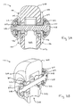
- FIGURE 3A is cross-sectional view of the bumper shown in FIGURE 2 through section line 3A-3A;
- FIGURE 3B is a perspective view of FIGURE 3A with the cross-hatching removed;
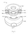
- FIGURE 4 is a perspective view of the bumper housing
- FIGURE 5A is a partial perspective view of the lift apparatus and hanger bar attachment bumper
- FIGURE 5B is a partial perspective view of the lift apparatus and hanger bar attachment bumper with the lower portion of the bumper housing removed;
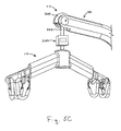
- FIGURE 5C is a partial perspective view of the lift apparatus and hanger bar attachment bumper with the lower portion of the bumper housing removed and an attached weight scale.
- Patient lift apparatuses may take a variety of different forms and may be used in a wide variety of different applications. This detailed description is applicable to patient lift apparatuses of varying construction.
- Apparatus 100 includes a central frame portion 102, base frame portion with caster leg assemblies 104, and a boom portion 106.
- the patient lift apparatus 100 may be provided without caster leg assemblies 104.
- Boom portion 106 is connected to central frame portion 102 through a pivot joint 107, which allows boom portion 106 to pivot with respect to central frame portion 102.
- the boom portion 106 and central frame portion 102 may be of a one-piece, unitary construction.
- An actuator 108 is provided to mechanically assist boom portion 106 to pivot about central frame portion 102.
- Actuator 108 can be, for example, an electrically driven screw-type, hydraulic, pneumatic or other similar type actuator. As described herein, when two or more objects are described as being connected, joined, affixed, or linked, they can be so connected, joined, affixed or linked directly to each other or through one or more intermediary parts or components.
- Boom portion 106 further includes a hanger assembly 110 and a hanger bar attachment bumper 112.
- Attached to hanger assembly 110 is typically a sling (not shown) for holding a patient during lifting and transport.
- Hanger assembly 110 may also be provided with additional attachments or accessories.
- Hanger 110 is typically connected to boom portion 106 through a pivot joint 109 or other suitable connection mechanism, such as a swivel joint. Pivot joint 109 allows hanger assembly 110 to pivot as boom portion 106 is raised or lowered.
- a hanger bar attachment bumper 112 is shown generally co-located with pivot joint 109.
- Bumper 112 includes, for example, first and second housing portions 200 and 202.
- housing portions 200 and 202 are designed to connect and disconnect from each other in use.
- Lower housing portion 202 includes projecting members 204 that interface with upper housing portion 200. Projecting members 204 are wider in cross-section at their mid-sections than ends. This configuration provides a snap-fit type/friction fitting for removable connection to apertures located in upper housing portion 200 (shown in detail in FIGURE 4 ). Other configurations are also possible for the snap-fit/friction connection.
- Upper and lower housing portions 200 and 202 are preferably made of rubber or other material so as to provide a soft impact surface.
- Lower housing portion 202 also includes, for example, inner lateral projections 206 and space 208 therebetween. Space 208 allows for a shoulder bolt 210 to reside between lateral projections 206. Lateral projections 206 in lower housing portion 202 and aperture 220 in upper housing portion 200 assist in guiding shoulder bolt 210 through the bumper 112.
- shoulder bolt 210 Received on shoulder bolt 210 are a plurality of components including, for example, washers 212, bushings 214, spacers 216 and nut 217.
- Bushings 214 are coaxially mounted in holes located at the end of boom 106 and provide a low-friction rotational support for shoulder bolt 210.
- Flanged washers 212 provide a mounting feature that retains soft impact cushioning caps 218 over the shoulder bolt 210 head and nut ends to cover any hard or sharp surfaces (as shown in the cross-sectional view of FIGURE 3A ).
- upper housing portion 200 is larger than lower portion 202 in that it includes more of the overall bumper housing circumference compared to lower housing portion 202. Accordingly, the upper housing portion 200 makes up a larger portion of the surface area of the bumper 112 than the lower housing portion 202. In this manner, removal of lower housing portion 202 minimizes the amount of soft impact material that is removed when lower housing portion 202 is removed from the bumper 112. In other embodiments, the proportion of material or circumference between the two housing portions may be approximately equal, or opposite from the illustrated embodiment, or any other ratio or proportion.
- FIGURES 3A and 3B illustrate various cross-section views of the hanger bar attachment bumper 112 in its assembled state through cross-section lines 3-3 of FIGURE 2 .
- bumper 212 In its assembled state, bumper 212 includes space 302. Space 302 allows a swivel bar 502 of hanger assembly 110 (shown in FIGURE 5A ) to connect to the shoulder bolt 210. The shoulder bolt 210 and swivel bar 502 thus form the pivot joint between the boom portion 106 and hanger assembly 110.
- FIGURE 4 illustrates a perspective view of hanger bar attachment bumper 112 showing the lower sections of upper housing portion 200 and lower housing portion 202.
- Upper housing portion 200 includes apertures or slots 402 for receiving projection members 204 of lower housing portion 202.
- the apertures/slots 402 are offset from a central section of upper housing portion 200 through which shoulder bolt 210 is inserted and resides.
- apertures/slots 402 are located proximate the outer circumferential surface of upper housing portion 200. These locations are not critical and can be modified or adjusted.
- apertures or slots 402 are shown and four projecting members 204 are shown.
- the number of apertures or slots 402 and projecting members 204 can be modified to include more of less than four, such as for example two or six apertures/slots and corresponding projecting members.
- the exact form of releasable connection between upper and lower housing portions 200 and 202 is not critical, so long as the two housing portions can be easily removed and reconnected to each other.
- FIGURES 5A, 5B and 5C are partial perspective views of boom 106, hanger assembly 110 and bumper 112.
- bumper 112 is shown with upper and lower housing portions 200 and 202 connected to each other.
- the diameter or overall geometric configuration of bumper 112 is such that it extends beyond the extremities of the end portion of boom 106. This configuration effectively provides a soft impact surface at the end of boom 106.
- FIGURE 5B shows bumper 112 with the lower housing portion 202 removed. Because upper housing portion 200 is still resident, the end portion of boom 106 still includes a soft impact surface provided by the bumper 112.
- FIGURE 5C illustrates boom 106 with a weight scale 500 attached thereto.
- other accessories may also be attached to end of boom 106 through bumper 112 such as, for example, a sling cradle. Hence, complete removal of bumper 112 is not necessary when attaching or using accessories such as a weight scale, hanger bar, or cradle to the end of boom portion 106.
- any type of releasable connection may be suitable including for example, locking connections, fastened connections, tongue and groove connections, etc.
- component geometries, shapes, and dimensions can be modified without changing the overall role or function of the components.
- the bumper 112 may include an oval, rounded polygon, or irregular geometry. Therefore, the inventive concept, in its broader aspects, is not limited to the specific details, the representative apparatus, and illustrative examples shown and described.
Landscapes
- Health & Medical Sciences (AREA)
- Nursing (AREA)
- Life Sciences & Earth Sciences (AREA)
- Animal Behavior & Ethology (AREA)
- General Health & Medical Sciences (AREA)
- Public Health (AREA)
- Veterinary Medicine (AREA)
- Invalid Beds And Related Equipment (AREA)
Description
- Devices for lifting and transporting patients are an important tool for caregivers and medical staff. They prevent caregiver and staff injuries such as, for example, back and other related injuries, and ensure dignity in patient handling. Such devices are typically configured to allow for attachment of a scale to measure a patient's weight. As such, these devices must be low maintenance, easy to use and safe for the caregiver and patient even when modified or retrofitted, for example, with a weight scale or other accessory attachment.
- Document
US2006026755 discloses a patient lift apparatus according to the preamble of claim 1. - In accordance with one aspect of the present invention, a patient lift apparatus according to claim 1, is provided that includes a hanger bar attachment bumper that comprises a soft material so as to provide a soft impact surface on the patient lift apparatus, the hanger bar attachment comprising a first and second housing adapted to be selectively connected to one another.
- The drawings are only for the purpose of illustrating preferred embodiments and are not to be construed as limiting the invention.
-
FIGURE 1 is a perspective view of one embodiment of a patient lift apparatus; -
FIGURE 2 is an exploded perspective view of one embodiment of a hanger bar attachment bumper; -
FIGURE 3A is cross-sectional view of the bumper shown inFIGURE 2 throughsection line 3A-3A; -
FIGURE 3B is a perspective view ofFIGURE 3A with the cross-hatching removed; -
FIGURE 4 is a perspective view of the bumper housing; -
FIGURE 5A is a partial perspective view of the lift apparatus and hanger bar attachment bumper; -
FIGURE 5B is a partial perspective view of the lift apparatus and hanger bar attachment bumper with the lower portion of the bumper housing removed; and -
FIGURE 5C is a partial perspective view of the lift apparatus and hanger bar attachment bumper with the lower portion of the bumper housing removed and an attached weight scale. - Referring to the FIGURES, this detailed description discloses embodiments of patient lift apparatuses. Patient lift apparatuses may take a variety of different forms and may be used in a wide variety of different applications. This detailed description is applicable to patient lift apparatuses of varying construction.
- Referring to
FIGURE 1 , a perspective view of an exemplary embodiment of apatient lift apparatus 100 is illustrated.Apparatus 100 includes acentral frame portion 102, base frame portion withcaster leg assemblies 104, and aboom portion 106. In additional embodiments, thepatient lift apparatus 100 may be provided withoutcaster leg assemblies 104.Boom portion 106 is connected tocentral frame portion 102 through apivot joint 107, which allowsboom portion 106 to pivot with respect tocentral frame portion 102. In additional embodiments, theboom portion 106 andcentral frame portion 102 may be of a one-piece, unitary construction. Anactuator 108 is provided to mechanically assistboom portion 106 to pivot aboutcentral frame portion 102.Actuator 108 can be, for example, an electrically driven screw-type, hydraulic, pneumatic or other similar type actuator. As described herein, when two or more objects are described as being connected, joined, affixed, or linked, they can be so connected, joined, affixed or linked directly to each other or through one or more intermediary parts or components. -
Boom portion 106 further includes ahanger assembly 110 and a hangerbar attachment bumper 112. Attached tohanger assembly 110 is typically a sling (not shown) for holding a patient during lifting and transport.Hanger assembly 110 may also be provided with additional attachments or accessories.Hanger 110 is typically connected toboom portion 106 through apivot joint 109 or other suitable connection mechanism, such as a swivel joint.Pivot joint 109 allowshanger assembly 110 to pivot asboom portion 106 is raised or lowered. One embodiment of a hangerbar attachment bumper 112 is shown generally co-located withpivot joint 109. - Referring now to
FIGURE 2 , an exploded perspective view of the hangerbar attachment bumper 112 is shown. Bumper 112 includes, for example, first andsecond housing portions housing portions Lower housing portion 202 includes projectingmembers 204 that interface withupper housing portion 200. Projectingmembers 204 are wider in cross-section at their mid-sections than ends. This configuration provides a snap-fit type/friction fitting for removable connection to apertures located in upper housing portion 200 (shown in detail inFIGURE 4 ). Other configurations are also possible for the snap-fit/friction connection. Upper andlower housing portions -
Lower housing portion 202 also includes, for example, innerlateral projections 206 andspace 208 therebetween. Space 208 allows for ashoulder bolt 210 to reside betweenlateral projections 206.Lateral projections 206 inlower housing portion 202 andaperture 220 inupper housing portion 200 assist in guidingshoulder bolt 210 through thebumper 112. - Received on
shoulder bolt 210 are a plurality of components including, for example,washers 212,bushings 214,spacers 216 andnut 217.Bushings 214 are coaxially mounted in holes located at the end ofboom 106 and provide a low-friction rotational support forshoulder bolt 210. Flangedwashers 212 provide a mounting feature that retains softimpact cushioning caps 218 over theshoulder bolt 210 head and nut ends to cover any hard or sharp surfaces (as shown in the cross-sectional view ofFIGURE 3A ). - In the embodiment shown,
upper housing portion 200 is larger thanlower portion 202 in that it includes more of the overall bumper housing circumference compared tolower housing portion 202. Accordingly, theupper housing portion 200 makes up a larger portion of the surface area of thebumper 112 than thelower housing portion 202. In this manner, removal oflower housing portion 202 minimizes the amount of soft impact material that is removed whenlower housing portion 202 is removed from thebumper 112. In other embodiments, the proportion of material or circumference between the two housing portions may be approximately equal, or opposite from the illustrated embodiment, or any other ratio or proportion. -
FIGURES 3A and 3B illustrate various cross-section views of the hangerbar attachment bumper 112 in its assembled state through cross-section lines 3-3 ofFIGURE 2 . In its assembled state,bumper 212 includesspace 302.Space 302 allows aswivel bar 502 of hanger assembly 110 (shown inFIGURE 5A ) to connect to theshoulder bolt 210. Theshoulder bolt 210 andswivel bar 502 thus form the pivot joint between theboom portion 106 andhanger assembly 110. -
FIGURE 4 illustrates a perspective view of hangerbar attachment bumper 112 showing the lower sections ofupper housing portion 200 andlower housing portion 202.Upper housing portion 200 includes apertures orslots 402 for receivingprojection members 204 oflower housing portion 202. The apertures/slots 402 are offset from a central section ofupper housing portion 200 through whichshoulder bolt 210 is inserted and resides. Also, apertures/slots 402 are located proximate the outer circumferential surface ofupper housing portion 200. These locations are not critical and can be modified or adjusted. - In the embodiment, four apertures or
slots 402 are shown and four projectingmembers 204 are shown. In other embodiments, the number of apertures orslots 402 and projectingmembers 204 can be modified to include more of less than four, such as for example two or six apertures/slots and corresponding projecting members. As described earlier, the exact form of releasable connection between upper andlower housing portions -
FIGURES 5A, 5B and5C are partial perspective views ofboom 106,hanger assembly 110 andbumper 112. InFIGURE 5A ,bumper 112 is shown with upper andlower housing portions bumper 112 is such that it extends beyond the extremities of the end portion ofboom 106. This configuration effectively provides a soft impact surface at the end ofboom 106. -
FIGURE 5B showsbumper 112 with thelower housing portion 202 removed. Becauseupper housing portion 200 is still resident, the end portion ofboom 106 still includes a soft impact surface provided by thebumper 112.FIGURE 5C illustratesboom 106 with aweight scale 500 attached thereto. In addition or alternatively, other accessories may also be attached to end ofboom 106 throughbumper 112 such as, for example, a sling cradle. Hence, complete removal ofbumper 112 is not necessary when attaching or using accessories such as a weight scale, hanger bar, or cradle to the end ofboom portion 106. - While the present invention has been illustrated by the description of embodiments thereof, and while the embodiments have been described in considerable detail, it is not the intention of the applicants to restrict or in any way limit the scope of the invention to such details. Additional advantages and modifications will readily appear to those skilled in the art. For example, where components are releasably connected together, any type of releasable connection may be suitable including for example, locking connections, fastened connections, tongue and groove connections, etc. Still further, component geometries, shapes, and dimensions can be modified without changing the overall role or function of the components. For example, the
bumper 112 may include an oval, rounded polygon, or irregular geometry. Therefore, the inventive concept, in its broader aspects, is not limited to the specific details, the representative apparatus, and illustrative examples shown and described.
Claims (14)
- A patient lift apparatus (100) comprising:a frame portion (102);a boom portion (106) connected to the frame portion;a hanger assembly (110) connected to the boom portion;characterized in that the patient lift apparatus further comprises a hanger bar attachment bumper (112) comprising a soft material so as to provide a soft impact surface on the boom portion and comprising a first and second housing (200, 202) adapted to be selectively connected to one another.
- The patient lift apparatus of claim 1, wherein one of the first and second housing (200, 202) comprises a plurality of projecting members (204) and the other of the first and second housing comprises a plurality of openings (402) adapted to receive the plurality of projecting members to selectively secure the first housing to the second housing.
- The patient lift apparatus of claim 2, wherein the plurality of projecting members (204) have a larger cross-sectional area at their midpoint than at their ends.
- The patient lift apparatus of claim 1, wherein the hanger bar attachment bumper (112) is adapted to receive a bolt (210), wherein the hanger assembly (110) attaches to the bolt, the hanger assembly thereby being connected to the boom portion (106).
- The patient lift apparatus of claim 4, wherein the hanger assembly (110) further comprises a swivel bar (502) that attaches to the bolt (210).
- The patient lift apparatus of claim 4, further comprising a weight scale (500) located between the boom portion (106) and the hanger assembly (110).
- The patient lift apparatus of claim 4, wherein one of the first and second housings (200, 202) of the hanger bar attachment bumper (112) is adapted to be removed to allow access to an interior of the hanger bar attachment bumper thereby permitting the hanger assembly (110) to be selectively connected or disconnected from the bolt (210), wherein the other of the first and second housing remains attached to the boom portion (106) so as to provide a soft impact surface on the boom portion.
- The patient lift apparatus of claim 1, further comprising a weight scale (500) located between the boom portion (106) and the hanger assembly (110).
- The patient lift apparatus according to any one of the preceding claims, wherein the hanger assembly (110) is connected to the boom portion (106) at a connection point (109) and the hanger bar attachment bumper (112) is generally co-located with said connection point (109), wherein the hanger bar attachment bumper comprises a surface area, and wherein the first housing (202) makes up a larger portion of the surface area of the hanger bar attachment bumper than the second housing (202).
- A hanger bar attachment bumper (112) suitable for a patient lift (100) comprising a frome portion (102), a boom portion (106) connected to the frame portion and a hangar assembly (110) connected to the boom portion, characterized in that the hanger bar attachment bumper comprises a soft material so as to provide a soft impact surface on the boom portion, and comprises a first and second housing (200, 202) adapted to be selectively connected to one another.
- The hanger bar attachment bumper of claim 10, wherein one of the first and second housing (200, 202) comprises a plurality of projecting members (204) and the other of the first and second housing comprises a plurality of openings (402) adapted to receive the plurality of projecting members to selectively secure the first housing to the second housing.
- The hanger bar attachment bumper of claim 11, wherein the plurality of projecting members (204) have a larger cross-sectional area at their midpoint than at their ends.
- The hanger bar attachment bumper of claim 11, wherein the hanger bar attachment bumper comprises a surface area and wherein one of the first housing and second housing (200, 202) makes up a larger portion of said surface area than the other of the first and second housing.
- The hanger bar attachment bumper of claim 13, wherein one of the first housing (200) and second housing (202) is adapted to be removed to allow access to an interior of the hanger bar attachment bumper.
Applications Claiming Priority (2)
| Application Number | Priority Date | Filing Date | Title |
|---|---|---|---|
| US7945408P | 2008-07-10 | 2008-07-10 | |
| PCT/US2009/050221 WO2010006240A1 (en) | 2008-07-10 | 2009-07-10 | Patient lift with hanger bar attachment |
Publications (3)
| Publication Number | Publication Date |
|---|---|
| EP2296601A1 EP2296601A1 (en) | 2011-03-23 |
| EP2296601B1 true EP2296601B1 (en) | 2013-02-13 |
| EP2296601B9 EP2296601B9 (en) | 2013-04-17 |
Family
ID=41119275
Family Applications (1)
| Application Number | Title | Priority Date | Filing Date |
|---|---|---|---|
| EP09790267.0A Not-in-force EP2296601B9 (en) | 2008-07-10 | 2009-07-10 | Patient lift with hanger bar attachment |
Country Status (6)
| Country | Link |
|---|---|
| US (1) | US8272084B2 (en) |
| EP (1) | EP2296601B9 (en) |
| AU (1) | AU2009268484B2 (en) |
| CA (1) | CA2730084C (en) |
| NZ (1) | NZ590353A (en) |
| WO (1) | WO2010006240A1 (en) |
Families Citing this family (21)
| Publication number | Priority date | Publication date | Assignee | Title |
|---|---|---|---|---|
| NZ590353A (en) | 2008-07-10 | 2013-08-30 | Invacare Corp | Patient lift with hanger bar attachment |
| EP2508159B1 (en) | 2008-08-07 | 2014-03-26 | Invacare Corporation | Patient lift with sling hooks |
| JP5886746B2 (en) * | 2009-09-24 | 2016-03-16 | アリオ・ホスピタル・イクウィップメント・アーベー | Patient lift and coupler therefor |
| US9222498B2 (en) * | 2011-09-08 | 2015-12-29 | Arjohuntleigh Magog, Inc. | Lifting bar and lifting bar connector |
| CN102688131A (en) * | 2012-05-14 | 2012-09-26 | 洛阳圣瑞机电技术有限公司 | Lifting apparatus for nursing care |
| TWI450712B (en) * | 2012-05-30 | 2014-09-01 | Wang Yi Lung | Apparatus for turning over and transferring patient |
| US9463128B2 (en) * | 2012-11-01 | 2016-10-11 | Liko Research & Development Ab | Lift system with status indicators |
| CN103006402A (en) * | 2013-01-22 | 2013-04-03 | 王业忠 | Medical lifting and moving device |
| CN103398765A (en) * | 2013-08-13 | 2013-11-20 | 上海市杨浦区中心医院 | Horizontal body weight measuring instrument |
| CA2934886A1 (en) * | 2013-10-07 | 2015-04-16 | Daniel R. Tekulve | Portable rehab station |
| US8935814B1 (en) * | 2014-01-25 | 2015-01-20 | Ton Duc Thang University | Method and apparatus for an automatic patient lift |
| USD839793S1 (en) * | 2016-09-23 | 2019-02-05 | Home Medical Products Inc. | Patient lift |
| US10864127B1 (en) | 2017-05-09 | 2020-12-15 | Pride Mobility Products Corporation | System and method for correcting steering of a vehicle |
| GB2562749B (en) * | 2017-05-23 | 2022-03-23 | Huntleigh Technology Ltd | Flexible leg supporting membrane, leg support frame and mobile patient standing and raising aid |
| USD839792S1 (en) * | 2017-08-25 | 2019-02-05 | Apex Health Care Mfg., Inc. | Patient carrier |
| EP3501471A1 (en) * | 2017-12-19 | 2019-06-26 | Invacare International GmbH | Patient lift apparatus |
| US10869796B1 (en) | 2019-07-11 | 2020-12-22 | Deborrah McBride Mathews | Rotating leg lift machine |
| USD974692S1 (en) * | 2020-08-10 | 2023-01-03 | John D. Cullinan | Vehicle hardtop lift |
| US12448258B1 (en) | 2020-10-28 | 2025-10-21 | John D. Cullinan | Apparatus and method for removal of vehicle hardtop |
| USD1079015S1 (en) * | 2023-08-28 | 2025-06-10 | Infinitus Medical Technologies Llc | Patient lift |
| USD1092750S1 (en) * | 2024-01-19 | 2025-09-09 | Infinitus Medical Technologies, LLC | Patient lift |
Family Cites Families (28)
| Publication number | Priority date | Publication date | Assignee | Title |
|---|---|---|---|---|
| US1901377A (en) * | 1929-05-10 | 1933-03-14 | Colson Company | Buffer |
| GB1347536A (en) | 1971-05-28 | 1974-02-27 | Mecanaids Ltd | Invalid lifting means |
| FR2274273A1 (en) | 1974-06-17 | 1976-01-09 | Bakker Anna Christina | DISMOUNTABLE COUPLING |
| DK162371C (en) * | 1985-12-21 | 1992-03-23 | Impro Ltd | DISCOVERY OF THE DISABLED |
| EP0739194B1 (en) | 1994-01-11 | 2000-07-05 | InterCare Scandinavia A/S | A hoist for handling a patient and a feet-supporting plate assembly to be used in connection with a hoist for handling a patient |
| AU125632S (en) | 1995-01-27 | 1996-01-16 | Arjo Med Atkiebolag Ltd | Patient lifting hoist |
| US5579547A (en) | 1995-08-23 | 1996-12-03 | Hunt; Dermot A. | Patient lift-transfer mechanism for gurney |
| US5892180A (en) | 1997-02-03 | 1999-04-06 | Medcare Products, L.C. | Patient hoist and scale |
| DE29720658U1 (en) | 1997-11-21 | 1999-04-01 | Hase, Marec, 44795 Bochum | Standing device for the rehabilitation area |
| CA2302060A1 (en) | 2000-03-23 | 2001-09-23 | Medi-Man Rehabilitation Products Inc. | Patient hoist and weighing apparatus |
| AU2002317115A1 (en) | 2000-09-15 | 2004-01-23 | 614641 N.B. Inc. | A winch assembly for the displacement of a person between a first vertical position and a second vertical position. |
| US6806430B2 (en) | 2001-04-23 | 2004-10-19 | Ez Way, Inc. | Patient lift and scale |
| FR2841450B3 (en) * | 2002-07-01 | 2004-09-10 | Claude Moufflet | DESCRIPTION OF THE PLASTIC SHOWCASE DISPLAY |
| EP1589923B1 (en) | 2003-02-03 | 2013-05-15 | HeCare Systems ApS | System and user interface for handling a person, and method therefor |
| PT1444971E (en) | 2003-02-05 | 2012-07-12 | Ergolet As | Spreader bar or floor lift with safety hook |
| DE20303002U1 (en) | 2003-02-25 | 2003-06-26 | Sander, Wolfgang, 63679 Schotten | Patient lift has an adjustable seat and a rolling belt in connection with a lift which moves patients in an ergonomic fashion |
| US6857144B1 (en) | 2003-08-12 | 2005-02-22 | Chi-Tzung Huang | Foldable lift and transfer apparatus for patient |
| JP2005111113A (en) | 2003-10-10 | 2005-04-28 | Mikuni Corp | Care lift |
| US7657951B2 (en) | 2004-06-14 | 2010-02-09 | Ez Way, Inc. | Support and transfer apparatus for transport of an incapacitated individual |
| US20060026755A1 (en) * | 2004-08-05 | 2006-02-09 | Bain Colin C | Patient lift with integrated foot push pad |
| US20060045708A1 (en) | 2004-08-05 | 2006-03-02 | Bain Colin C | Patient lift with three-point vertical stance |
| US7428759B2 (en) | 2004-08-05 | 2008-09-30 | Joerns Healthcare Inc. | Patient lift with support legs that spread over two ranges of motion |
| US20060048297A1 (en) | 2004-09-09 | 2006-03-09 | Michael Mills | Portable lift device |
| US8458869B2 (en) * | 2005-03-29 | 2013-06-11 | John Giannasca | Adjustable connector |
| CA2656877C (en) | 2006-07-07 | 2012-12-04 | Arjo Hospital Equipment Ab | Hoist device with sling attachment detection |
| US7921486B2 (en) | 2007-12-27 | 2011-04-12 | Joerns Healthcare, Llc | Multi-position support for a folding patient lift device |
| NZ590353A (en) | 2008-07-10 | 2013-08-30 | Invacare Corp | Patient lift with hanger bar attachment |
| EP2508159B1 (en) | 2008-08-07 | 2014-03-26 | Invacare Corporation | Patient lift with sling hooks |
-
2009
- 2009-07-10 NZ NZ590353A patent/NZ590353A/en unknown
- 2009-07-10 CA CA2730084A patent/CA2730084C/en active Active
- 2009-07-10 US US12/500,855 patent/US8272084B2/en active Active
- 2009-07-10 WO PCT/US2009/050221 patent/WO2010006240A1/en not_active Ceased
- 2009-07-10 EP EP09790267.0A patent/EP2296601B9/en not_active Not-in-force
- 2009-07-10 AU AU2009268484A patent/AU2009268484B2/en not_active Ceased
Also Published As
| Publication number | Publication date |
|---|---|
| EP2296601A1 (en) | 2011-03-23 |
| HK1155352A1 (en) | 2012-05-18 |
| CA2730084A1 (en) | 2010-01-14 |
| CA2730084C (en) | 2013-10-08 |
| US20100005585A1 (en) | 2010-01-14 |
| US8272084B2 (en) | 2012-09-25 |
| NZ590353A (en) | 2013-08-30 |
| WO2010006240A1 (en) | 2010-01-14 |
| AU2009268484A1 (en) | 2010-01-14 |
| EP2296601B9 (en) | 2013-04-17 |
| WO2010006240A8 (en) | 2010-04-29 |
| AU2009268484B2 (en) | 2013-05-16 |
Similar Documents
| Publication | Publication Date | Title |
|---|---|---|
| EP2296601B9 (en) | Patient lift with hanger bar attachment | |
| EP1521565B1 (en) | A winch assembly for the displacement of a person between a first vertical position and a second vertical position | |
| US8313066B2 (en) | Intravenous fluid container stand and methods for making same | |
| CA2664385C (en) | Medical equipment transfer arrangement | |
| US6273444B1 (en) | Apparatus for coupling wheelchairs to ventilator carts | |
| US5699988A (en) | Coupler clamping apparatus for interconnecting a free-standing, wheeled intravenous pole with mobile patient transfer devices | |
| US8443472B2 (en) | Litter attachment bracket | |
| JP5407085B2 (en) | Patient position exchange and limb handling system | |
| US20110138532A1 (en) | Patient lift and transfer device | |
| NZ590594A (en) | Patient lift with knee pad having rail selectively securable to guide portion | |
| AU2006202439A1 (en) | I.V. support stand and clamp apparatus | |
| EP3727267B1 (en) | Patient lift apparatus | |
| US11141240B2 (en) | Transfer device docking indicator | |
| HK1155352B (en) | Patient lift with hanger bar attachment | |
| WO2022053918A2 (en) | Patient lift apparatus | |
| US20220133569A1 (en) | Patient lift apparatus | |
| US7308742B2 (en) | Hardware for mounting a casket handle | |
| CN219921396U (en) | Wheelchair and patient transfer system | |
| JPS63500568A (en) | patient lifting device | |
| US20090013474A1 (en) | Offset patient trapeze system | |
| EP3967286A1 (en) | Patient lift apparatus |
Legal Events
| Date | Code | Title | Description |
|---|---|---|---|
| PUAI | Public reference made under article 153(3) epc to a published international application that has entered the european phase |
Free format text: ORIGINAL CODE: 0009012 |
|
| 17P | Request for examination filed |
Effective date: 20110105 |
|
| AK | Designated contracting states |
Kind code of ref document: A1 Designated state(s): AT BE BG CH CY CZ DE DK EE ES FI FR GB GR HR HU IE IS IT LI LT LU LV MC MK MT NL NO PL PT RO SE SI SK SM TR |
|
| AX | Request for extension of the european patent |
Extension state: AL BA RS |
|
| DAX | Request for extension of the european patent (deleted) | ||
| REG | Reference to a national code |
Ref country code: HK Ref legal event code: DE Ref document number: 1155352 Country of ref document: HK |
|
| GRAP | Despatch of communication of intention to grant a patent |
Free format text: ORIGINAL CODE: EPIDOSNIGR1 |
|
| GRAS | Grant fee paid |
Free format text: ORIGINAL CODE: EPIDOSNIGR3 |
|
| GRAA | (expected) grant |
Free format text: ORIGINAL CODE: 0009210 |
|
| AK | Designated contracting states |
Kind code of ref document: B1 Designated state(s): AT BE BG CH CY CZ DE DK EE ES FI FR GB GR HR HU IE IS IT LI LT LU LV MC MK MT NL NO PL PT RO SE SI SK SM TR |
|
| REG | Reference to a national code |
Ref country code: GB Ref legal event code: FG4D |
|
| REG | Reference to a national code |
Ref country code: AT Ref legal event code: REF Ref document number: 596074 Country of ref document: AT Kind code of ref document: T Effective date: 20130215 |
|
| REG | Reference to a national code |
Ref country code: IE Ref legal event code: FG4D |
|
| REG | Reference to a national code |
Ref country code: DE Ref legal event code: R096 Ref document number: 602009013315 Country of ref document: DE Effective date: 20130411 |
|
| REG | Reference to a national code |
Ref country code: AT Ref legal event code: MK05 Ref document number: 596074 Country of ref document: AT Kind code of ref document: T Effective date: 20130213 |
|
| REG | Reference to a national code |
Ref country code: NL Ref legal event code: VDEP Effective date: 20130213 |
|
| REG | Reference to a national code |
Ref country code: LT Ref legal event code: MG4D |
|
| PG25 | Lapsed in a contracting state [announced via postgrant information from national office to epo] |
Ref country code: NO Free format text: LAPSE BECAUSE OF FAILURE TO SUBMIT A TRANSLATION OF THE DESCRIPTION OR TO PAY THE FEE WITHIN THE PRESCRIBED TIME-LIMIT Effective date: 20130513 Ref country code: IS Free format text: LAPSE BECAUSE OF FAILURE TO SUBMIT A TRANSLATION OF THE DESCRIPTION OR TO PAY THE FEE WITHIN THE PRESCRIBED TIME-LIMIT Effective date: 20130613 Ref country code: ES Free format text: LAPSE BECAUSE OF FAILURE TO SUBMIT A TRANSLATION OF THE DESCRIPTION OR TO PAY THE FEE WITHIN THE PRESCRIBED TIME-LIMIT Effective date: 20130524 Ref country code: AT Free format text: LAPSE BECAUSE OF FAILURE TO SUBMIT A TRANSLATION OF THE DESCRIPTION OR TO PAY THE FEE WITHIN THE PRESCRIBED TIME-LIMIT Effective date: 20130213 Ref country code: SE Free format text: LAPSE BECAUSE OF FAILURE TO SUBMIT A TRANSLATION OF THE DESCRIPTION OR TO PAY THE FEE WITHIN THE PRESCRIBED TIME-LIMIT Effective date: 20130213 Ref country code: LT Free format text: LAPSE BECAUSE OF FAILURE TO SUBMIT A TRANSLATION OF THE DESCRIPTION OR TO PAY THE FEE WITHIN THE PRESCRIBED TIME-LIMIT Effective date: 20130213 Ref country code: BG Free format text: LAPSE BECAUSE OF FAILURE TO SUBMIT A TRANSLATION OF THE DESCRIPTION OR TO PAY THE FEE WITHIN THE PRESCRIBED TIME-LIMIT Effective date: 20130513 |
|
| PG25 | Lapsed in a contracting state [announced via postgrant information from national office to epo] |
Ref country code: GR Free format text: LAPSE BECAUSE OF FAILURE TO SUBMIT A TRANSLATION OF THE DESCRIPTION OR TO PAY THE FEE WITHIN THE PRESCRIBED TIME-LIMIT Effective date: 20130514 Ref country code: BE Free format text: LAPSE BECAUSE OF FAILURE TO SUBMIT A TRANSLATION OF THE DESCRIPTION OR TO PAY THE FEE WITHIN THE PRESCRIBED TIME-LIMIT Effective date: 20130213 Ref country code: PT Free format text: LAPSE BECAUSE OF FAILURE TO SUBMIT A TRANSLATION OF THE DESCRIPTION OR TO PAY THE FEE WITHIN THE PRESCRIBED TIME-LIMIT Effective date: 20130613 Ref country code: FI Free format text: LAPSE BECAUSE OF FAILURE TO SUBMIT A TRANSLATION OF THE DESCRIPTION OR TO PAY THE FEE WITHIN THE PRESCRIBED TIME-LIMIT Effective date: 20130213 Ref country code: LV Free format text: LAPSE BECAUSE OF FAILURE TO SUBMIT A TRANSLATION OF THE DESCRIPTION OR TO PAY THE FEE WITHIN THE PRESCRIBED TIME-LIMIT Effective date: 20130213 Ref country code: SI Free format text: LAPSE BECAUSE OF FAILURE TO SUBMIT A TRANSLATION OF THE DESCRIPTION OR TO PAY THE FEE WITHIN THE PRESCRIBED TIME-LIMIT Effective date: 20130213 Ref country code: PL Free format text: LAPSE BECAUSE OF FAILURE TO SUBMIT A TRANSLATION OF THE DESCRIPTION OR TO PAY THE FEE WITHIN THE PRESCRIBED TIME-LIMIT Effective date: 20130213 |
|
| PG25 | Lapsed in a contracting state [announced via postgrant information from national office to epo] |
Ref country code: HR Free format text: LAPSE BECAUSE OF FAILURE TO SUBMIT A TRANSLATION OF THE DESCRIPTION OR TO PAY THE FEE WITHIN THE PRESCRIBED TIME-LIMIT Effective date: 20130213 |
|
| PG25 | Lapsed in a contracting state [announced via postgrant information from national office to epo] |
Ref country code: CZ Free format text: LAPSE BECAUSE OF FAILURE TO SUBMIT A TRANSLATION OF THE DESCRIPTION OR TO PAY THE FEE WITHIN THE PRESCRIBED TIME-LIMIT Effective date: 20130213 Ref country code: EE Free format text: LAPSE BECAUSE OF FAILURE TO SUBMIT A TRANSLATION OF THE DESCRIPTION OR TO PAY THE FEE WITHIN THE PRESCRIBED TIME-LIMIT Effective date: 20130213 Ref country code: RO Free format text: LAPSE BECAUSE OF FAILURE TO SUBMIT A TRANSLATION OF THE DESCRIPTION OR TO PAY THE FEE WITHIN THE PRESCRIBED TIME-LIMIT Effective date: 20130213 Ref country code: DK Free format text: LAPSE BECAUSE OF FAILURE TO SUBMIT A TRANSLATION OF THE DESCRIPTION OR TO PAY THE FEE WITHIN THE PRESCRIBED TIME-LIMIT Effective date: 20130213 Ref country code: NL Free format text: LAPSE BECAUSE OF FAILURE TO SUBMIT A TRANSLATION OF THE DESCRIPTION OR TO PAY THE FEE WITHIN THE PRESCRIBED TIME-LIMIT Effective date: 20130213 Ref country code: SK Free format text: LAPSE BECAUSE OF FAILURE TO SUBMIT A TRANSLATION OF THE DESCRIPTION OR TO PAY THE FEE WITHIN THE PRESCRIBED TIME-LIMIT Effective date: 20130213 |
|
| PLBE | No opposition filed within time limit |
Free format text: ORIGINAL CODE: 0009261 |
|
| STAA | Information on the status of an ep patent application or granted ep patent |
Free format text: STATUS: NO OPPOSITION FILED WITHIN TIME LIMIT |
|
| PG25 | Lapsed in a contracting state [announced via postgrant information from national office to epo] |
Ref country code: IT Free format text: LAPSE BECAUSE OF FAILURE TO SUBMIT A TRANSLATION OF THE DESCRIPTION OR TO PAY THE FEE WITHIN THE PRESCRIBED TIME-LIMIT Effective date: 20130213 |
|
| 26N | No opposition filed |
Effective date: 20131114 |
|
| REG | Reference to a national code |
Ref country code: DE Ref legal event code: R097 Ref document number: 602009013315 Country of ref document: DE Effective date: 20131114 |
|
| PG25 | Lapsed in a contracting state [announced via postgrant information from national office to epo] |
Ref country code: MC Free format text: LAPSE BECAUSE OF FAILURE TO SUBMIT A TRANSLATION OF THE DESCRIPTION OR TO PAY THE FEE WITHIN THE PRESCRIBED TIME-LIMIT Effective date: 20130213 |
|
| REG | Reference to a national code |
Ref country code: CH Ref legal event code: PL |
|
| REG | Reference to a national code |
Ref country code: IE Ref legal event code: MM4A |
|
| PG25 | Lapsed in a contracting state [announced via postgrant information from national office to epo] |
Ref country code: LI Free format text: LAPSE BECAUSE OF NON-PAYMENT OF DUE FEES Effective date: 20130731 Ref country code: CH Free format text: LAPSE BECAUSE OF NON-PAYMENT OF DUE FEES Effective date: 20130731 |
|
| PG25 | Lapsed in a contracting state [announced via postgrant information from national office to epo] |
Ref country code: IE Free format text: LAPSE BECAUSE OF NON-PAYMENT OF DUE FEES Effective date: 20130710 |
|
| PG25 | Lapsed in a contracting state [announced via postgrant information from national office to epo] |
Ref country code: SM Free format text: LAPSE BECAUSE OF FAILURE TO SUBMIT A TRANSLATION OF THE DESCRIPTION OR TO PAY THE FEE WITHIN THE PRESCRIBED TIME-LIMIT Effective date: 20130213 |
|
| PG25 | Lapsed in a contracting state [announced via postgrant information from national office to epo] |
Ref country code: MT Free format text: LAPSE BECAUSE OF FAILURE TO SUBMIT A TRANSLATION OF THE DESCRIPTION OR TO PAY THE FEE WITHIN THE PRESCRIBED TIME-LIMIT Effective date: 20130213 Ref country code: TR Free format text: LAPSE BECAUSE OF FAILURE TO SUBMIT A TRANSLATION OF THE DESCRIPTION OR TO PAY THE FEE WITHIN THE PRESCRIBED TIME-LIMIT Effective date: 20130213 Ref country code: CY Free format text: LAPSE BECAUSE OF FAILURE TO SUBMIT A TRANSLATION OF THE DESCRIPTION OR TO PAY THE FEE WITHIN THE PRESCRIBED TIME-LIMIT Effective date: 20130213 |
|
| PG25 | Lapsed in a contracting state [announced via postgrant information from national office to epo] |
Ref country code: HU Free format text: LAPSE BECAUSE OF FAILURE TO SUBMIT A TRANSLATION OF THE DESCRIPTION OR TO PAY THE FEE WITHIN THE PRESCRIBED TIME-LIMIT; INVALID AB INITIO Effective date: 20090710 Ref country code: MK Free format text: LAPSE BECAUSE OF FAILURE TO SUBMIT A TRANSLATION OF THE DESCRIPTION OR TO PAY THE FEE WITHIN THE PRESCRIBED TIME-LIMIT Effective date: 20130213 Ref country code: LU Free format text: LAPSE BECAUSE OF NON-PAYMENT OF DUE FEES Effective date: 20130710 |
|
| REG | Reference to a national code |
Ref country code: FR Ref legal event code: PLFP Year of fee payment: 8 |
|
| REG | Reference to a national code |
Ref country code: FR Ref legal event code: PLFP Year of fee payment: 9 |
|
| REG | Reference to a national code |
Ref country code: FR Ref legal event code: PLFP Year of fee payment: 10 |
|
| REG | Reference to a national code |
Ref country code: DE Ref legal event code: R082 Ref document number: 602009013315 Country of ref document: DE Representative=s name: KARAKATSANIS, GEORGIOS, DR., DE |
|
| PGFP | Annual fee paid to national office [announced via postgrant information from national office to epo] |
Ref country code: DE Payment date: 20240719 Year of fee payment: 16 |
|
| PGFP | Annual fee paid to national office [announced via postgrant information from national office to epo] |
Ref country code: GB Payment date: 20240723 Year of fee payment: 16 |
|
| PGFP | Annual fee paid to national office [announced via postgrant information from national office to epo] |
Ref country code: FR Payment date: 20240729 Year of fee payment: 16 |
|
| REG | Reference to a national code |
Ref country code: DE Ref legal event code: R119 Ref document number: 602009013315 Country of ref document: DE |
|
| GBPC | Gb: european patent ceased through non-payment of renewal fee |
Effective date: 20250710 |
|
| PG25 | Lapsed in a contracting state [announced via postgrant information from national office to epo] |
Ref country code: GB Free format text: LAPSE BECAUSE OF NON-PAYMENT OF DUE FEES Effective date: 20250710 |
|
| PG25 | Lapsed in a contracting state [announced via postgrant information from national office to epo] |
Ref country code: DE Free format text: LAPSE BECAUSE OF NON-PAYMENT OF DUE FEES Effective date: 20260203 |
|
| PG25 | Lapsed in a contracting state [announced via postgrant information from national office to epo] |
Ref country code: FR Free format text: LAPSE BECAUSE OF NON-PAYMENT OF DUE FEES Effective date: 20250731 |